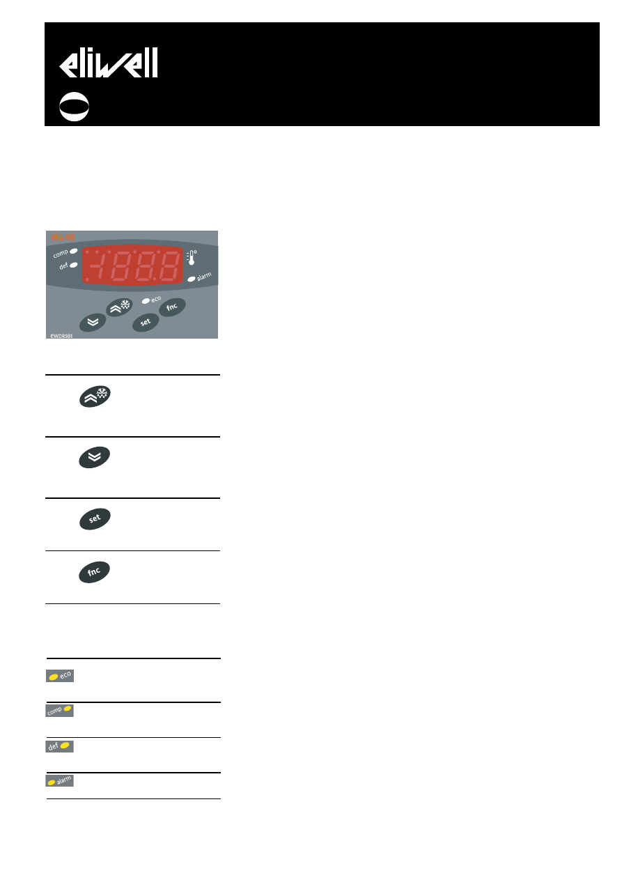
USER INTERFACE
The user interface has a 4 LED display to
indicate status and alarms and four buttons
for controlling instrument status and pro-
gramming.
KEYS
UP
Increase in value of
parameter
Menu scrolling and
activation of defrost
function
(Parameter programmable
H31)
DOWN
Decrease in value of
parameter
Menu scrolling and
activation of associated
function
(Parameter programmable
H32)
set
Access to different levels of
menu
Alarm display, set
point and probes
Access to programming of
parameters
fnc
Exit current level of
menu
Confirmation of value of para-
meter
(Parameter programmable
H33)
SIGNAL LED
The status of the external devices, functions
and controllers is described by the device
LEDs.
DISPLAY
This is used to display the inputs, the set
point, the parameters and related values,
alarms, functions and the status of the
device.
DESCRIPTION OF MENU
Access to both menus is controlled by
the ‘set’ button. If it is pressed and
immediately released, the ‘machine
status menu‘ is displayed. Hold the same
button down for 5 seconds to access the
‘parameter programming menu‘.
When one of the two menus has been
accessed, you can navigate between the
level 1 folders using the ‘UP’ and ‘DOWN’
buttons. The folders are opened by
pressing the ‘set’ button once. You can
now scroll through the contents of each
folder, modify it or use its functions.
You can exit each level of both menus in
three ways: using the ‘fnc’ button, if a
new value is confirmed by pressing the
‘set’ button or, when the time-out has
elapsed (15 seconds inactivity on the
device).
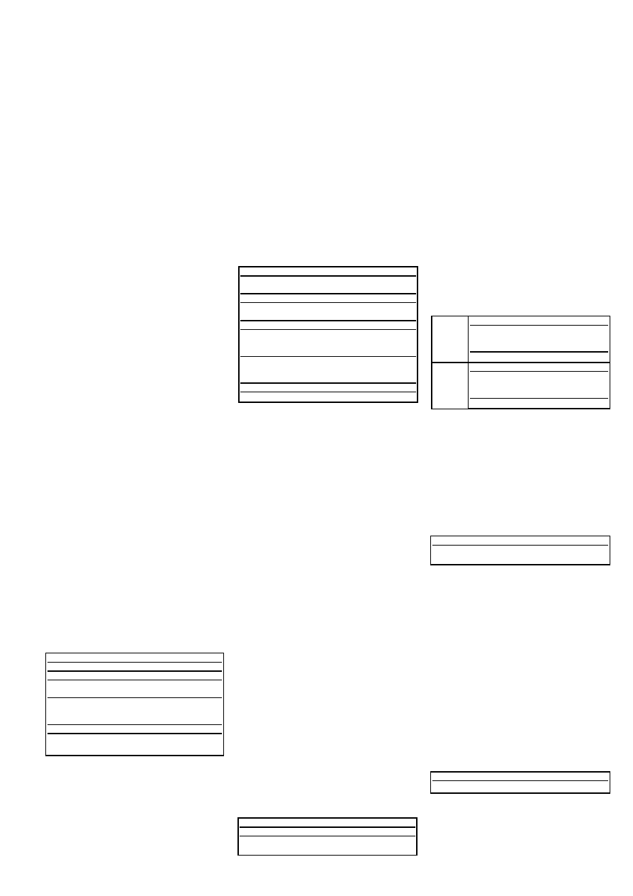
MACHINE STATUS MENU
The ‘machine status menu’ contains the
folders and basic information on the
device:
-AL: alarm folder
-SEt: Set point setting folder
-Pb1: ‘probe 1 value’ folder
-Pb3: ‘probe 3 value’ folder
If no alarms are present, the “SEt” label
is displayed. From here, you can scroll
down the other menu items using the
UP’ and ‘DOWN’ buttons.
Each folder can be accessed by pressing
the ‘set’ button once. Values are
modified using the ‘UP’ and ‘DOWN’
buttons and the ‘set’ button that
confirms the selected value and takes
you back to the higher level.
Setting the set point
Access the ‘machine status menu’. If no
alarms are present, the “SEt” label is
displayed. By pressing and immediately
releasing the ‘set’ button, the set point
value can be set using the UP’ and
‘DOWN’ buttons. Press and release the
‘set’ button again or press the ‘fnc’
button to go back to the main menu
level. The set point setting folder is also
closed when the time-out elapses.
Alarm on
If an alarm condition exists when the
Machine Status menu is accessed the
“ALfolder label appears.
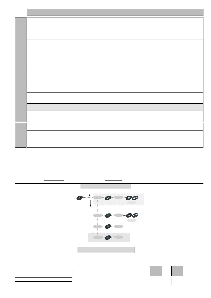
PARAMETER PROGRAMMING MENU
Access the menu by pressing the ‘set’
button for at least 5 seconds.
The menu structure enables all
parameter folders to be divided into two
levels.
All the level 1 folders can be accessed
by entering the password ‘PA1’.
Scroll down the level 1 folders using the
‘UP’ and ‘DOWN’ buttons. Press and
release the ‘set’ button next to the
selected label to access the parameters.
Scroll through the labels in the folder
using the ‘UP’ and ‘DOWN’ buttons,
press ‘set’ to display the current value of
the selected parameter, use the ‘UP’ and
‘DOWN’ buttons and set the required
value by pressing ‘set’.
To access the level 2 folders in the ‘Cnf’
folder, select the ‘PA2’ label, enter the
password ‘PA2’ and confirm with the ‘set’
button. All the parameters that cannot
be changed at level 1 are in this level.
NOTE: Level 1 parameters will only be
displayed if you quit the ‘parameter
programming menu’ and repeat the
steps for manipulation of level 1
folders.
The steps to follow for manipulation of
level 2 parameters are the same as those
NOTE: It is strongly recommended
that the instrument is switched off
and on again each time parameter
configuration is changed in order to
prevent malfunctioning of the
configuration and/or ongoing timings.
PASSWORD
The passwords “PA1and “PA2” are used
to access level 1 and level 2 parameters.
To change them and assign them the
desired value, access the ‘parameter
programming menu’ in the “diS” label
folder.
The password is requested:
- PA1 when entering the ‘parameter
programming menu’;
- PA2 in the “Cnf” folder containing the
level 1 parameters.
USING COPY CARD
The Copy card function can be used to
upload and download parameter maps
of one or more of the same type of
instrument.
The accessory is connected to the device
using the special TTL serial port on the
instrument. The Copy card can be used
for the following functions:
EWDR 981
electronic controllers for refrigeration units
cod. 9IS43091
rel. 3/05
GB
LED
Description
Indication
reduced set point
Lights up when
inserted
LED set point is dis-
played, blinking
when reduced set
point is inserted
compressor LED
‘on’ with LED on.
Blinking for delay,
protection or acti-
vation blocked
defrost LED
‘on’ during defrost-
ing. Blinking when
activated manually
or by digital input
alarm LED
‘on’ if alarm is pre-
sent. Blinking for
silenced
alarm decimal point
‘on’ to indicate of
voltage when on
stand-by and dis-
play ‘off’
Upload (UL): The upload function reads
the instrument parameters and writes
them onto the Copy card
Download(dL): The download function
writes the parameter map that is on the
copy card at that time onto the
instrument memory.
NOTE:
Upload = instrument—-> Copy card
Download = Copy card —> instrument
The operations are performed by
accessing the folder with the ‘FPr’ label
and selecting the ‘UL’, ’dL’ or ‘Fr’
commands. The operation is confirmed
by pressing the ‘set’ button. If the
operation is successful, a “y” is displayed
whereas if it is unsuccessful an “n” will
be displayed.
Formatting the copy card
This function is necessary when using the
copy card for uploading for the first
time or when using the copy card on
device models that are not compatible.
NOTE: formatting deletes all the data
on the Copy card and cannot be
undone.
Download from reset
Once the copy card has been connected
the instrument is switched on. When the
lamp test is over, one of the following
two labels will be displayed for 5
seconds:
- dLY if the operation is successful
- label DLn if operation fails The display
will then go into default position (probe
or set point).
NOTE: after downloading, the
instrument will begin to work with
the new parameter map that has just
been downloaded.
ADVANCED FUNCTIONS
DOOR SWITCH INPUT
This is a clean contact digital input with
programmable polarity. The door switch
input functions are controlled by the
values of the following parameters:
Parameter H11 is used to configure the
door switch input with values between
-8 and +8. Positive and negative values
are present in order to select the
polarity assigned to the input and:
NOTE: the sign “-” indicates that the
input is activated when the contact is
closed.
The ‘+’ sign indicates that the input is
activated when the contact is open
LIGHT CONTROLLER
Controls the light relay. The function can
be started in two different ways. If you
press the light button the light relay is
switched on if it was off and is switched
off if it was on.
The light status is recorded by the
device as soon as the button is pressed
so that when power is restored after a
black-out the device can continue to
operate in the same way as before the
power failure.
The following parameters control how
the light works:
The configuration of these parameters
controls the status of the light relay by
using the digital input as well as the
normal button.
The parameter dSd automatically
switches on the light relay when the
digital input is enabled and switches it
off when the digital input is disabled
following the delay set by parameter dLt.
Parameter H06 activates the light button
and enables the relay when the door is
open even when the instrument is
powered but is ‘off’.
The dedicated button always deactivates
the light relay even if the digital input is
on or during the dLt delay only if the
parameter OFL=Y.
DIAGNOSTICS
PROBE ALARMS
When one of the probes is outside the
nominal operating range or the probe is
open or has shorted, an alarm is
generated if at least one of these
conditions persists for at least 10
seconds.
If at least one of these 3 alarms is
signalled the alarm LED and relay are
enabled. When activated code E1
appears on the display.
If several alarms are activated at the
same time, they are displayed alternately
for 2 seconds each. An error condition
in the room probe leads to:
- E1 code appears on display
- activation of compressor as indicated
by Ont and OFt
- deactivation of maximum and
minimum alarm controller.
MINIMUM AND MAXIMUM
TEMPERATURE
ALARM
The alarm is regulated on the room
probe. The temperature limits are
defined by parameters HAL and LAL. The
limits refer to the set point if parameter
Att=1 and are absolute if Att=0.
NOTE: If the alarms are relative, the
parameter HA1 is set to positive
values and LA1 to negative values.
ALARM WITH THRESHOLD REFERRING
TO PROBE 3
An alarm is associated with probe 3 that
refers to a threshold that is reset at a
specified differential.
By setting parameter PbA=3 probe 3 will
signal a high or low temperature alarm
for exceeding the set value.
The alarm is handled in the same way as
the other temperature alarms and
standard signal delays are used.
EXTERNAL ALARM
It is set if the digital input is enabled
with the delay specified by parameter
dAd and remains enabled until the next
time the digital input is deactivated. The
alarm consists of an alarm LED that
remains on, activation of a buzzer and
deactivation of all the device loads (if
specified by the EAL parameter).
If an external alarm is present the EA
label is displayed in the AL folder.
It is reset the next time the digital input
is deactivated and the buzzer can be
manually silenced.
Par
Description
dOd
Digital input switches off loads
dAd
D.I. activation delay
OAO
Alarm signal delay after dis-
disabling the digital input (door closed)
tdO
Time out door open. Time out
signal after activation of D.I.
(door open)
H11
Digital output configurability/polarity 1
H21...H25
Digital output configurability 1...5
Par
Description
H06
Button/aux input/door switch light active
when instrument off
dSd
Enabling light relay by door switch
dLt
Delay Light Relay
deactivation delay
OFL
Light switch always disables light relay
OAO
Alarm signal delay after
disabling the digital input
(door closed)
tdO
Time out door open.
Time out signal after activation of D.I.
(door open)
H11
Digital output configurability/polarity 1
H21...H25
Digital output configurability 1...5
Signal
Description
E1
Faulty room probe
E3
Faulty display probe
EWDR 981
2/8
Att=0
absolute
Maximum temperature alarm
room probe temperature ≥ HAL
Minimum temperature alarm
room probe temperature ≤ LAL
Att=1
relative
Maximum temperature alarm
room probe temperature ≥ Set + HAL
Minimum temperature alarm room
probe temperature ≤ Set + LAL
Signal
Description
AH3
High temperature alarm
AL3
Low temperature alarm
Signal
Description
EA
External alarm

OPEN DOOR ALARM
This alarm is generated when the door is
open for longer than the value specified
in parameter tdO. The door open alarm
is signalled in the alarm folder (AL) and
the LED and alarm relay are switched on.
The OPd label is also displayed.
The relay can be deactivated by pressing
the silencing button. The LED continues
to flash intermittently and the OPd label
remains in the alarm menu until the
door is closed.
MECHANICAL
ASSEMBLY
The EWDR 981 is designed to be wall-
mounted (removable brackets) or
mounted on DIN rail (Omega 3). The
unit operates correctly with an ambient
temperature range of between -5 and 55
°C. Units must not be installed in
excessively humid and/or dirty locations.
TECHNICAL DATA
Casing: plastic 4 Din modules
Dimensions: front 70x85 mm, depth
61mm.
Mounting: on DIN rail (Omega 3) or
wall-mounted.
Connections: on screw terminal block for
≤ 2.5mm
2
conductors
(only one conductor per terminal block
for power connections)
Operating temperature: -5...55°C.
Storage temperature: -30...85°C.
Operating and storage ambient humidity:
10...90 % RH (non-condensing).
Display: 3 digits + sign
Analogue inputs: 2 NTC/PTC inputs
(parameter configurable)
Digital inputs: 2 voltage-free parameter-
configurable digital inputs.
Serial: TTL for Copy Card
Digital outputs: 1 on relay:
16A 1hp 250V SPDT;
Configurable 12V
c/24mA output
Resolution: 1 or 0.1°C.
Accuracy: better than 0.5% of bottom
scale +1 digit
Consumption: 5VA
Power supply: 230V
a
ELECTRICAL
CONNECTIONS
Warning! Always switch off machine
before working on electrical
connections.
The instrument has screw terminal blocks
for connecting cables with a maximum
diameter of 2.5 mm
2
(only one conductor
per terminal block for power
connections): for terminal capacity, see
the label on the instrument.
The relay outputs are voltage free.
Do not exceed the maximum current
allowed. For higher loads, use a suitable
contactor.
Make sure that the power voltage
complies with the device voltage.
Probes have no connection polarity and
can be extended using an ordinary
bipolar cable (note that if probes are
extended this affects the electromagnetic
compatibility (EMC) of the instrument:
special care must be used when wiring).
The TTL serial cable must be kept
separate from the power cables.
EWDR 981
3/8
CONDITIONS OF USE
PERMITTED USE
For safety reasons the instrument must
be installed and used in accordance with
the instructions supplied.
Users must not be able to access parts
with dangerous voltage levels under nor-
mal operating conditions. The device
must be suitably protected from water
and dust depending on the specific
application and only be accessible using
special tools (except for the front key-
pad).
The device is ideally suited for house-
hold use and/or similar use in the refrig-
eration sector and has been tested with
regard to safety in accordance with the
European harmonized reference stan-
dards. It is classified as follows:
• as an automatic electronic control
device to be independently mounted as
regards its construction;
• as a 1 B type operated control device
as regards its automatic operating fea-
tures;
• as a Class A device as regards the cate-
gory and structure of the software.
UNPERMITTED USE
The use of the unit for applications
other than those described above is for-
bidden. It should be noted that the relay
contacts supplied with the device are
functional and therefore exposed to
potential faults. Any protection devices
required to comply with product
requirements or dictated by common
sense due to obvious safety reasons
should be installed externally.
RESPONSIBILITY AND RESIDUAL RISKS
Eliwell shall not be liable for any damages deriving from:
- installation/use other than that prescribed and, in particular, which does not comply
with the safety standards specified in the regulations and/or those given herein;
- use on boards which do not guarantee proper protection against electric shock, water
or dust when assembled;
- use on boards which allow dangerous parts to be accessed without the use of tools;
- tampering with and/or alteration of the product;
- installation/use on boards that do not comply with the standards and regulations in
force.
Signal
Description
OPd
Open door alarm

PAR.
DESCRIPTION
RANGE
DEFAULT
VALUE
LEVEL
U.M.
SEt
Set point with range falling between the minimum
LSE set point and the maximum HSE set point. The
set point value is in the machine status menu
menu
LSE...HSE
0.0
°C/°F
diF
When the compressor stops when it reaches the
set point value, it restarts at a value corresponding
to the set point plus the value of the differential It
must not be 0
0.1...30.0
2.0
1-2
°C/°F
HSE
Maximum set point value
LSE...302
50.0
1-2
°C/°F
LSE
Minimum set point value
-58.0...HSE
-50.0
1-2
°C/°F
OSP
Offset point. Value to be added to set point if
reduced set point is activated Economy function).
-30.0...30.0
0
2
°C/°F
Cit
Minimum compressor ON time. Minimum time for
activating a compressor before deacti vation Not
active if=0
0...250
0
2
min
CAt
Maximum compressor ON time. Maximum time for
activating a compressor before deacti vation Not
active if=0
0...250
0
2
min
Ont (1)
Compressor activation time if probe is faulty. If set
to 1 with OFt=0 the compressor always remains on
whereas if OFt>0 it operates in duty cycle mode
(see Duty Cyclediagram)
0...250
0
1-2
min
OFt (1)
Compressor shut-down time if probe is faulty. If set
to 1 with Ont=0 the compressor always remains off
whereas if OFt>0 it operates in duty cycle mode
(see Duty Cyclediagram)
0...250
1
1-2
min
dOn
Delay in activating compressor relay after start-up
0...250
0
1-2
sec
dOF
Delay after shut-down; between compressor relay
shut-down and subsequentstart-up the specified
time must elapse.
0...250
0
1-2
min
dbi
Delay between switch-ons; the specified time must
elapse between two subsequent switch-ons
0...250
0
1-2
min
OdO
Delay in activating outputs after start-up of instru-
ment or after a power failure.
Not active if=0
0...250
0
1-2
min
dty
Type of defrost.
0 = electrical defrosting;
1 = cycle reversing defrosting (hot gas);
2 = Free mode defrosting (compressor disabled).
0/1/2
0
1-2
num
dit
Period of time elapsing between the start of two
defrosts 0=function disabled
0...250
6h
1-2
hours/min/sec
dt1
Unit of measurement for defrost
times (par. dit)
0=”dit” expressed in hours
1=”dit” expressed in minutes
2=”dit” expressed in seconds
0/1/2
0
2
num
NOTE: At level 1 the folders will only display all the level 1 parameters. At level 2 the folders will only display all the level
2 parameters. The symbol 1-2 indicates the parameters that are displayed at both menu levels
Defrosting controller
-dEF label
Compressor controller
-CP label
dt2
Unit of measurement for duration of defrosting
(dEt parameter)
0= “dEt” parameter expressed in hours
1= “dEt” parameter expressed in minutes
2= “dEt” parameter expressed in seconds
0/1/2
1
2
num
dCt
Selection of defrosting time count mode.
0=compressor operating hours DIGIFROST®
method). Defrosting active only if compressor is
on.
1 = device operating hours; defrost counting is
always active when the machine is on
2=compressor stop Each time the compressor
stops a defrosting cycle
defrost cycle is performed according to par. dtY
3=disabled
0/1/2/3
1
1-2
flag
dOH
Delay between start of first defrosting operation
and start-up of instrument.
0...59
0
1-2
min
dEt
Defrosting time-out; determines maximum dura-
tion of defrosting.
1...250
30min
1-2
min/sec
EWDR 981
4/8

PAR.
DESCRIPTION
RANGE
DEFAULT
VALUE*
LEVEL**
U.M.
dPO
Determines when instrument starts up if
the defrosting cycle must be activated (if the
temperature on the evaporator allows this)
y=defrosting activated at start-up
n=defrosting not activated at start-up
n/y
n
1-2
flag
tcd
minimum time for each compressor state
before defrosting “Ontime if >0; “Offtime if >0
-31...31
0
2
min
Cod
Compressor “Off” time before defrost cycle.
The compressor is not turned on if a defrost cycle
is expected in the time indicated by the parameter.
0=Function excluded
0...60
0
2
min
Defrosting controller
-dEF label
NOTE: At level 1 the folders will only display all the level 1 parameters. At level 2 the folders will only display all the
level 2 parameters. The symbol 1-2 indicates the parameters that are displayed at both menu levels
Alarms-AL label
Att
Determines if “LAL” and “HAL” are expressed as
absolute values or as a differential related to the
set point
0=absolute value
1=value related to set point
0/1
0
2
flag
AFd
Alarm differential
1.0...50.0
2.0
1-2
°C/°F
HAL (2)
Maximum alarm. Temperature limit (whose
absolute or relative value status is regulated by
“Att”) above which the alarm is activated.
LAL...150.0
50.0
1-2
°C/°F
LAL (2)
Minimum alarm. Temperature limit (whose
absolute or relative value status is regulated by
“Att”) below which the alarm is activated.
-50.0...HAL
-50.0
1-2
°C/°F
PAO (3)
Alarm exclusion time after start-up of instrument
following a power failure
0...10
0
1-2
hours
dAO
Alarm exclusion time after defrosting
0...999
0
1-2
min
EWDR 981
5/8
OAO
High and low temperature alarm delay after
disabling digital input
(door closed)
0...10
0
2
hours
tdO
Time out after alarm signal when
digital input is
disabled (door open)
0...250
0
2
min
tAO (3)
Temperature alarm delay time
0...250
0
1-2
min
EAL
External alarm to lock controllers
n=does not lock,
y=locks
n/y
n
2
flag
AOP
Polarity of alarm output:
0 = alarm active and output disabled;
1 = alarm active and output enabled
0/1
1
2
flag
PbA
Configuration of temperature alarm on
probe 1 and/or 3:
0=on probe 1 (thermostat control)
1=on probe 3 (display)
2=on probe 1 and 3 (thermostat control and display)
3=on probe 1 and 3 (thermostat control and display)
on external threshold
0/1/2/3
0
2
num
SA3
Probe 3 alarm set point
-50.0...150.0
50
2
°C/°F
dA3
Probe 3 alarm differential
-30.0...30.0
2.0
2
°C/°F
dt
Dripping time
0...250
0
1-2
min
Light & digital inputs
Lit Label
dLt
Light relay disabling delay after closing
door if “dSd”=y
0...31
0
2
min
OFL
Light relay disabled even if disabling delay
“dLt” is active
n/y
n
2
flag
dAd
Delay in activating digital input
0...255
0
2
min
dOd
Digital input switches off loads
n/y
n
2
flag
dSd
Light relay enable from door switch.
n = door open, light does not turn on;
y = door open, light turns on (if it was off)
n/y
y
2
flag

PAR.
DESCRIPTION
RANGE
DEFAULT
VALUE*
LEVEL**
U.M.
NOTE: At level 1 the folders will only display all the level 1 parameters. At level 2 the folders will only display all the
level 2 parameters. The symbol 1-2 indicates the parameters that are displayed at both menu levels
EWDR 981
6/8
LOC
Keyboard locked. Parameters can still be
programmed.
n= keyboard not locked
y= keyboard locked
n/y
n
1-2
flag
PA1
Contains the password for level 1 parameters.
Enabled if not 0
0...250
0
1
num
PA2
Contains the password for level 2 parameters.
Enabled if not 0
0...250
0
2
num
ndt
Display with decimal point.
n= without decimal point (only whole numbers)
y= with decimal point
n/y
n
1-2
flag
CA1
Temperature value to be added to that read
by probe 1 as specified by parameter CAI
-12.0...12.0
0
1-2
°C/°F
CA2
Temperature value to be added to that read
by probe 2 as specified by parameter CAI
-12.0...12.0
0
1-2
°C/°F
CA3
Temperature value to be added to that read
by probe 3 as specified by parameter CAI
-12.0...12.0
0
1
°C/°F
Display - diS label
CAI
Intervention of offset on display, thermostat
control or both:
0 = only modifies the temperature displayed
1 = adds to the temperature used by controllers
not the temperature displayed that remains
unchanged.
2= adds to temperature displayed that is
also used by controllers.
0/1/2
2
2
num
LdL
Minimum value that can be displayed
-55.0...140
-50.0
2
°C/°F
HdL
Maximum value that can be displayed
-50.0...302
140.0
2
°C/°F
ddL
display during defrosting:
0= displays temperature read by thermostat
control probe
1= displays temperature read entering
defrost cycle until set point is reached
2= displays “dEF” label during defrosting until
set point is reached (or when Ldd expires)
0/1/2
1
1-2
flag
Ldd
Time out for unlocking display (with ddL=2) if
defrosting lasts too long
0...255
0
1-2
min
dro (4)
Select °C or °F to display temperature:
0= °C 1= °F
0/1
0
1-2
flag
ddd
Value to be displayed:
0 = Set point
1 = probe 1 (thermostat control)
2 = disabled
3 = probe 3 (display)
0/1/2/3
1
2
num
H00
Selects probe, PTC or NTC 0= PTC 1= NTC
0/1
1
1-2
flag
H02
Quick activation time for functions with configured
buttons. Not possible for aux
(time expected = 1 second)
0...15
5
2
sec
H11 (5)
Configuration of digital inputs/polarity:
0= disabled
1 = defrost
2 = reduced set point 3 = auxiliary
4 = door switch
5= external alarm
6= disabled
7= stand-by (On/Off)
8= maintenance request
-8...8
4
2
num
H08
Stand-by operating mode
0= only display switched off;
1= display on and controls locked;
2= display off and controls locked
0/1/2
2
2
num
H06
Button/input aux/door switch light active when
instrument is off
n/y
y
2
flag
H12 (5)
Configuration of digital inputs/polarity
Same as H11
-8...8
0
2
num
Configuration- CnF label
PAR.
DESCRIPTION
RANGE
DEFAULT
VALUE*
LEVEL**
U.M.
Configuration- CnF label
EWDR 981
7/8
H21
Digital output configurability (C):
0= disabled
1= compressor
2= defrosting
3= fans
4= alarm
5= auxiliary
6= stand-by
7= light
8= buzzer
9= defrosting on 2nd
evaporator
0...9
1
2
num
H31
UP button configurability
0=disabled
1=defrosting
2=auxiliary
3=reduced set point
4=disabled
5=disabled
6=light
7=stand-by
8= maintenance request
H32
DOWN button configurability
Same as H31(0=disabled default)
0...8
0
2
num
H33
ESC button configurability
Same as H31(0=disabled default)
0...8
0
2
num
0...8
1
2
num
H41
Presence of control probe:
n= not present
y= present
n/y
y
2
num
H43
Presence of display probe:
n= not present
y= present (display probe)
n/y
y
2
flag
PA2***
in the CnF folder when you enter the correct password you can access level 2 parameters from label PA2 by pressing the “set” button
rEL
Device version. Read only parameter
/
/
1
/
tAb
Parameter table; Reserved; Read only parameter
/
/
1
/
Copy Card
Fpr label
UL
Transfer of parameter map from instrument to
Copy Card
dL
Transfer of parameter map from Copy Card to
instrument
Fr (6)
Formatting. Cancels all data in the Copy Card
/
/
1
/
/
/
1
/
/
/
1
/
NOTES:
(1) See Duty Cycle diagram
(2) If relative values are present (par. Att=1) parameter HAL is set to positive values and the parameter LAL is set to negative values (-LAL)
(3) Refers exclusively to high and low temperature alarms
(4) when changing from °C to °F or vice versa the set points, differentials, etc. are NOT converted (for example, “set=10 °C becomes set=10°F”)
(5) CAUTION: positive or negative values change polarity, Positive values: active input when contact is closed; Negative values: active input when contact is open.
(6) If the Fpr parameter is used, the data previously stored on the Copy Card will be permanently lost. This operation cannot be undone
* Value: to be compiled manually by user with any custom settings (if different from default settings)
** Level: indicates the visibility level of parameters accessed using a password (see relevant paragraph)
*** PA2 is visible at level 1 in the CnF folder whereas it can be modified at level 2 in the diS folder
H25
Digital output configuration. (E) Same as H11.
0...9
4
2
num
if alarm(s)
present
AL
Pb1
SEt
set
alarms
Pb1 value
SEt value
set
change SEt
value
show alarms
press and release
(quickly/single press)
Pb3
Pb3 value
is present
MACHINE STATUS MENU
Ont, OFt parameters programmed for
Duty Cycle
Ont
OFt
Compressor output
0
0
OFF
0
>0
OFF
>0
0
ON
>0
>0
dc
OUT
On
Off
OFt
Ont
Ont
The error condition for probe 1
(compressor) causes the following:
- E1 code appears on display
- the controller is activated as indicated by
the “Ont” and
“OFt” parameters if programmed for
Duty Cycle
DUTY CYCLE DIAGRAM
CP
dEF
AL
level 1 par
level 1 par
level 1 par
PA1›0
set PA1 value
diS
CnF
Fpr
level 1 par
level 1 par
level 1 par
level 2 par
level 2 par
level 2 par
level 2 par
level 2 par
CP
dEF
diS
CnF
PA2›0
set PA2 value
level 2
level 1
change
par value
scroll
parameters
press for 5 sec
level 2 par
Lit
AL
PA2
PROGRAMMING MENU
EWDR 981
8/8
The technical characteristics in this
document concerning measurements (range,
accuracy, resolution, etc.) refer to the
instrument in the strictest sense and not to
any accessories provided such as probes,
for example. This means that an error
introduced by the probe is added to any
error that is in the instrument.
Minimum temperature alarm
Maximum temperature alarm
LAL
AFd
HAL
AFd
1
set+ LAL
AFd
Off
set+HAL
AFd
set
2
Temperature lower than or equal to LAL (LAL with sign)
Temperature lower than or equal to set point+LAL (set-|LAL|)
(LAL only negative)
Temperature higher than or equal to HAL (HAL with sign)
Maximum temperature alarm
back swing
Minimum temperature alarm
back swing
Temperature higher than or equal to LAL+AFd
Temperature lower than or equal to HAL-AFd
Temperature expressed as an absolute value (par “Att0)
Abs(olute)
Temperature expressed in relation to set point
(par “Att”=0) reL(ative)
if Att=reL(ative) LAL must be negative: therefore set
point+LAL<set point because set point+(-|LAL|)=set point-|LAL|
MIN/MAX ALARM MENU
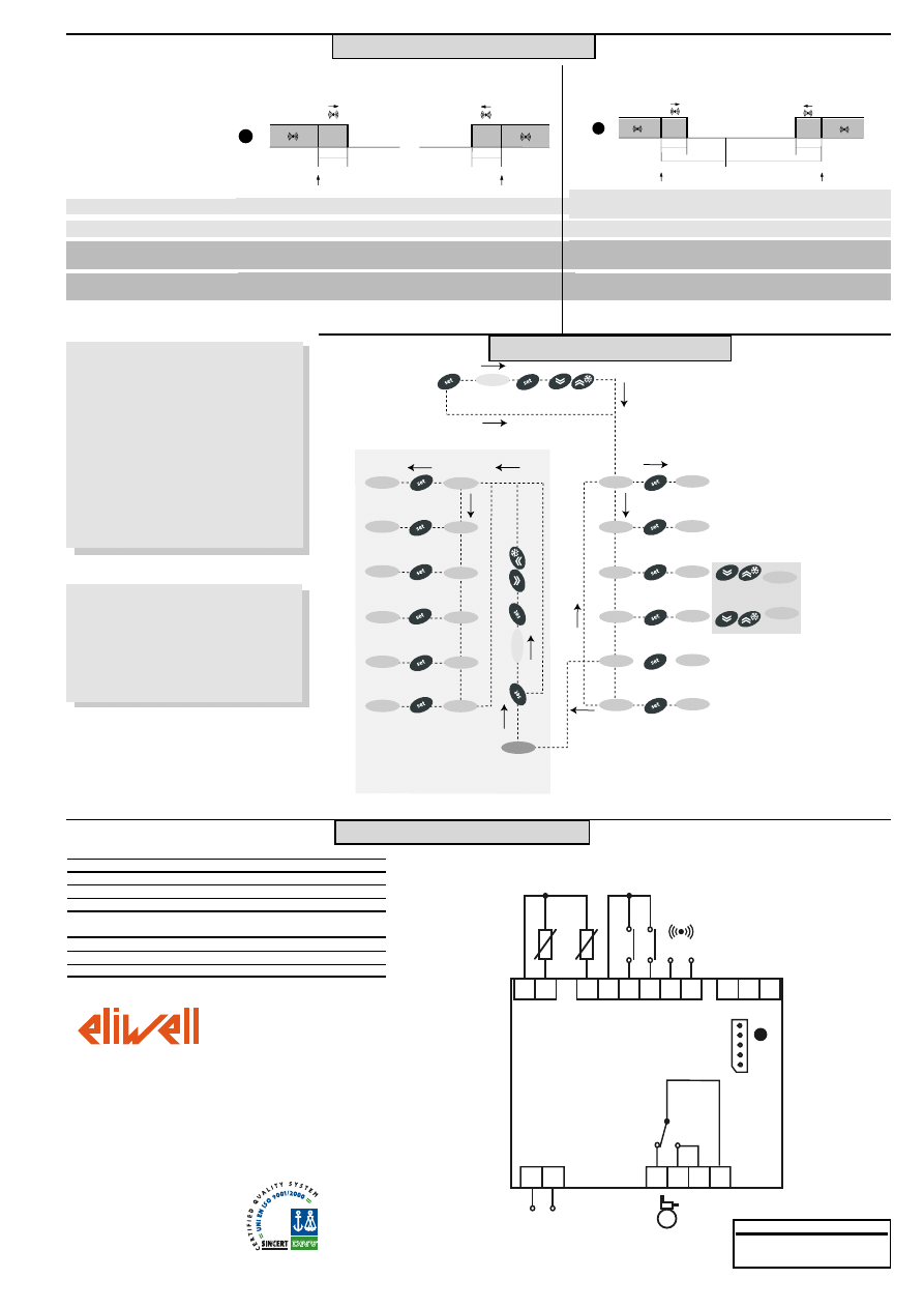
WIRING DIAGRAM
TERMINALS
1-2
Probe input 1 (room probe)
1-4
Probe input 3 (display or 2nd evaporator probe)
5-6
Digital input 1
5-7
Digital input 2
8-9
Auxiliary output 12V
c/20mA (E) see par. H25
(alarm default)
13-14
Power supply 230V
a
A
TTL input for Copy Card
20-21-22* N.O. relay output (C) see par. H21 (compressor default)
19-22*
N.C. relay output (C) see par. H21 (compressor default)
EWDR 981
1 2
4 5 6 7
8 9
10 11 12
13 14
19 20 21 22
TTL
A
(C)
AUX OUT
12V
C/20mA
P
o
w
e
r
S
u
p
p
ly
Pb1
Pb3
D
.I.1
D
.I.2
(E)
Eliwell & Controlli s.r.l.
Via dell'Industria, 15 Zona Industriale Paludi
32010 Pieve d'Alpago (BL) ITALY
Telephone +39 0437 986111
Facsimile +39 0437 989066
Internet http://www.eliwell.it
Technical Customer Support:
Email: techsuppeliwell@invensys.com
Telephone +39 0437 986300
Climate Controls Europe
An Invensys Company
3/05 eng
cod. 9IS43091
* Relay characteristics
Relay output (C) 16A 1hP 250V
a
DISCLAIMER
This document is the exclusive property of
Eliwell and cannot be reproduced and
circulated unless expressly authorized by
Eliwell.
Although Eliwell has taken all possible
measures to guarantee the accuracy of this
document, it declines any responsibility for any
damage arising out of its use.
The same applies to any person or company
involved in preparing and writing this
document. Eliwell reserves the right to make
any changes or improvements without prior
notice and at any time.
Temperature higher than or equal to set point+HAL (HAL only positive)
Temperature higher than or equal to set point + LAL + AFd
set point -|LAL|+AFd
Temperature lower than or equal to set point+HAL-AFd
Wyszukiwarka
Podobne podstrony:
981 wytyczne g 1 12 21 04 2008 1
EWDR 984
981
981
981 id 48808 Nieznany
E 981
981
981 wytyczne g 1 12 21 04 2008 1
EWDR 984
Lumley Brian Nekroskop II (SCAN dal 981)
Palmer Diana Long Tall Texans 35 Zimowe róże (Harlequin Romans 981)
więcej podobnych podstron