MAURER
Single Seal
Expansion Joints
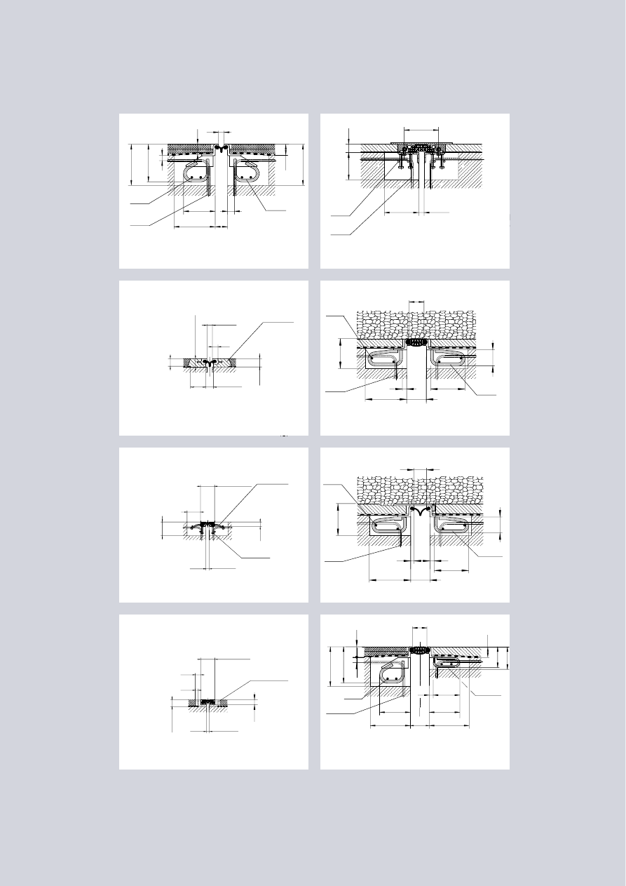
Betoflex
®
-Joint B 80 B
Compact joints K 30 (50) N-K
Compact joints K 30 (50) A-B
Railway joint DB 80 E
Railway joint DB 40
Railway joint DB 200
Elastoblock joint D 80 E
Road, Rail & Commercial Structures
Type D 80 for
road and highway
bridges with
standard blockout
dimensions.
Varieties of blockou-
ts,
anchorsystems as
well as footway
details are shown
in this brochure.
Betoflex
®
-Joints
B 80 B are surface
mounted and
anchored into a
cold processed
polymeric concrete.
Please ask for our
pertinent brochure.
K 30 N-K and
K 50 N-K
compact joints
for 30 and
50 mm movement
with stainless steel
edge beams and
anchor studs for
commercial
structures,
carparks etc.
K 30 A-B and
K 50 A-B
compact joints see
fig. above, however,
with aluminium
edge beams and
anchored into
Betoflex
®
. Please
ask for our perti-
nent brochure.
DB 40, DB 80
and DB 130
joints for move-
ments of 40, 80
and 130 mm
designed for
railway bridges.
Approved by
German Railway
Authority.
DB 80 E and
DB 100 E
elastoblock joints
for movements of
80 and 100 mm,
an alternative
design for railway
bridges.
DB 200 joint for
movements of up
to 200 mm for
railway bridges
with a sliding
plate above the
sealing element.
D 80 E and D 100
E elastoblock joints
for road and
pedestrian bridges.
min.
max.
0
80
Ø 20
e = 250
50
130
Ø 16
e = 200
Ø 16
230
300
50
300
275
var
.
50
Standard strip seal joint D 80
300
250
Ø 16
e = 200
Ø 16
≥ 250
60
200
min. 20
max. 60
Ø 16
e = 200
min.
max.
60
140
220
115
Ø 16
300
30
250
gap
Ø 20
e = 250
min.
max.
0
80
min.
120
40
min.
max.
15
95
min.
60
t
B
t
=
t
B
≥6
0
Betoflex
concrete
Ø 16
e = 200
min.
max.
0
200
220
300
275
157
170
50
var.
var.
115
Ø 16
300
25
250
gap
Ø 20
e = 250
Carriageway Footway
30
Ø 16
e = 200
300
230
300
100
180
Ø 14
e = 250
230
200
30
min.
max.
90 (95)
120 (145)
100
95
gap
Ø 10x50
e = 200
Ø 10x75
e = 200
10 (15)
40 (65)
34
min.
max.
90 (95)
120 (145)
min.
max.
60
140
min.
50
20
40
gap 10 (15)
40 (65)
35
Betoflex
concrete
Ø 16
70
Design
Research and
Development
Recognized throughout the world,
Maurer has been one of the leading
specialists of expansion joints for
over 25 years. Intensive develop-
ment work has been going on in
close co-operation with competent
research institutes forming the basis
for the design of MAURER
Expansion Joints. With their proven
record of success worldwide Maurer
is positioned to continue its acknow-
ledged assistance to the construc-
tion industry – advancing the state-
of-the-art.
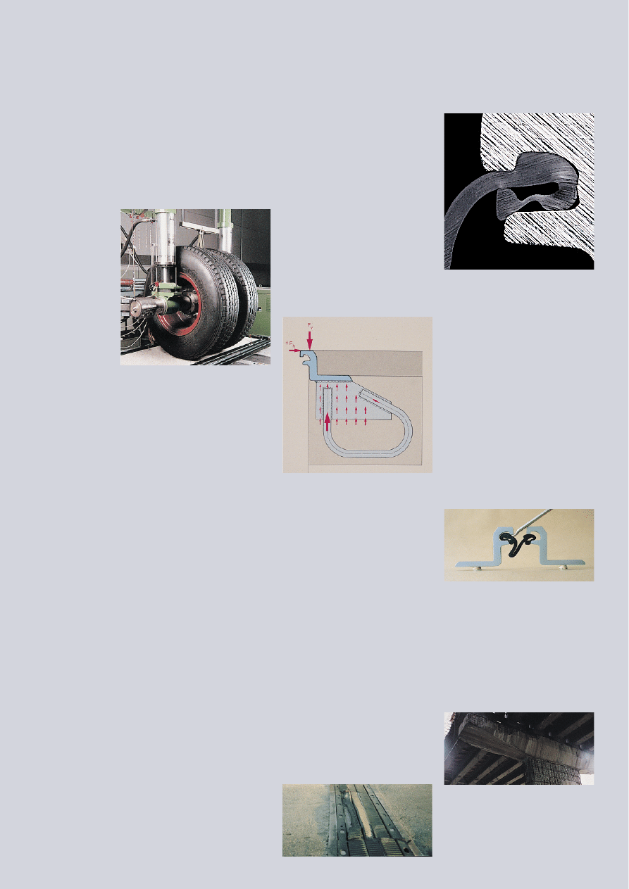
Testing
Expansion joints are the dynami-
cally heaviest loaded members of a
bridge structure. They are directly
exposed to traffic and thus subjec-
ted to
forces and aggressions whose
magnitudes or combinations are
rarely found in structural enginee-
ring. They must withstand dynamic
effects, impacts, fatigue, wear and
chemical as well as physical aggres-
sion.
To ensure long-term performance of
MAURER Expansion Joints, extensi-
ve and continuous tests have been
carried out on all major components
prior to their release for fabrication.
Watertightness
MAURER Expansion Joints feature
an extremely effective insertion prin-
ciple of the neoprene strip seal in
the grooves of the edge beams with-
out using any screwed or bolted
connections. The special bulbous
shape of the strip seal with its lan-
ding to a bead thickened end crea-
tes a wedge effect, when buttoned
into the edge beam and guarantees
absolute watertightness. Moreover,
it can be easily inserted and repla-
ced from the top of the road surface
with simple tools and it can be
connected together by means of
hot-vulcanising even on site.
The strip seal is protected from the
over-rolling traffic by the edge
beams and its V-shape generates a
self-cleaning effect. It can resist
pulling forces and also accommo–
date lateral and vertical movements.
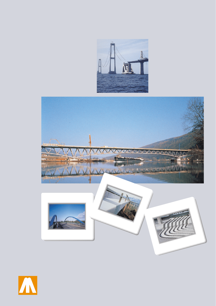
The harmful effects of a leaking
joint on a structure can be seen
from the picture.
The clear separation of the two
major design principles on single seal
joints, i.e. “rigid anchorage” and
“watertight sealing” allows a proper
design of both the components.
MAURER Expansion Joints fulfil all
load requirements such as German
Standards (DIN), British Standards
(BS) and American Standards
(ASTM). They are generally appro-
ved by the German Federal Ministry
of Transport.
Rigid Anchorage
Some experts say: “An expansion
joint is as good as its anchorage”,
and they are perfectly right. The
edge beams are rigidly connected to
the main structure by means of fati-
gue-tested anchors directly welded to
the edge beams.
They are embedded into the rein-
forcement to assure the utmost
resistance to the overrolling traffic.
The use of screwed or bolted con-
nections in the carriageway surface
directly exposed to wheel loads must
fail sooner or later. Such connections
tend to fail under permanent
dynamic traffic due to the lack of
a controlled prestressing force,
resulting in the need for regular
maintenance, repair and replace-
ment.
MAURER Joints have been develo-
ped in such a way as to clearly sepa-
rate the load carrying and sealing
function from each other. An expan-
sion joint designed to fulfil all func-
tions in one member must fail soo-
ner or later. Carrying traffic, sealing
the structural gap, accommodating
movements (without substantial
reaction forces) and disposing of a
durable anchorage cannot be combi-
ned in one joint component only.
125
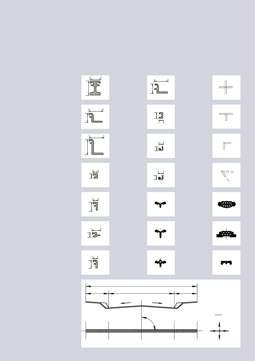
Joint Components
Centre Beam
No. 7.1002
Weight:
46.6 kg/m
Edge Beam
No. 7.0001
Weight:
18.2 kg/m
Edge Beam 120
No. 7.1100
Weight:
27.3 kg/m
Edge Beam BF
No. 7.0112
Weight:
10.2 kg/m
Edge Beam 70
No. 7.0008
Weight:
10.8 kg/m
Edge Beam 40
No. 7.0003
Weight:
8.1 kg/m
Edge Beam EB
No. 7.0026
Weight:
7,5 kg/m
Edge Beam SS
(stainless steel)
No. 7.0078
Weight:
2.8 kg/m
Edge Beam AL
(aluminium)
No. 7.0073
Weight:
1.64 kg/m
Edge Beam EB
No. 7.0009
Weight:
19.0 kg/m
Strip Seal 80
No. 7.0011
Weight:
1.65 kg/m
Strip Seal 100
No. 7.0012
Weight:
1.75 kg/m
(Seal 200 upon
request)
X-Piece 80
No. 2.0080
Weight:
3.1 kg
T-Piece 80
No. 2.0081
Weight:
2.3 kg
L-Piece 80
No. 2.0082
Weight:
1.5 kg
<-Piece 80
Weight:
1.5 kg
)-Piece 80
Elastoblock 80
No. 7.0016
Weight:
5.5 kg/m
(E-Block 100
upon request)
Flush Seal 40
No. 7.0143
Weight:
13.4 kg/m
(Seal 80 and 130
upon request)
Hot-rolled steel sections and steel extru-
sions in grade St 37-2 and St 52-3
(DIN) are equivalent to S235 JR and
S355 J2G3 (EN), to ASTM A 570 Grade
Inquiry Data
Edge Beam 75
No. 7.0146
Weight:
10.7 kg/m
Strip Seal 80G
No. 7.0130
Weight:
1.45 kg/m
36 and ASTM A 738 respectively as
well as to former British Standard
BS 4360/37 and 4360/52.
length of joint L = . . . . .
L1= . . .
L 3 = . . .
L 2 = . . .
%
%
D 80
+ 40
+ 40
– 40
– 40
α
= . . .°
90
125
120
80
variable
40
40
40
75
70
40
40
70
118
82
35
50
37
34
40
35
variable
Compact Seal
30 (50)
No. 7.0117 (7.0120)
Weight:
2.0 (2,5) kg/m
Footway with watertight fascia
Joint Junctions
Footway with cover plate
Footway without cover plate
The joint designs shown in this
brochure were made as comprehen-
sive as possible. However, there
are still numerous details we could
not refer to, for which we ask your
specific inquiry.
On highways and expressways
without footways the carriageway
joints are usually provided with a
vertical upturn at either end to
prevent water from deteriorating
the adjacent structural parts.
Barrier cover plates can be provi-
ded at extra cost.
Design Varieties
A permanent steel shuttering can
be supplied at extra cost reaching
to the lower part of the anchorage.
The remaining gap between this
shuttering and the blockout must
be closed by structural measures.
Please ask for a separate price if
you wish a permanent steel shut-
tering.
Footway with wedge plate and watertight fascia
wedge
plate
wedge
plate
footway
carriage-
way
formwork
(by MAURER)
formwork
(by others)
carriage-
way
footway
wedge
plate
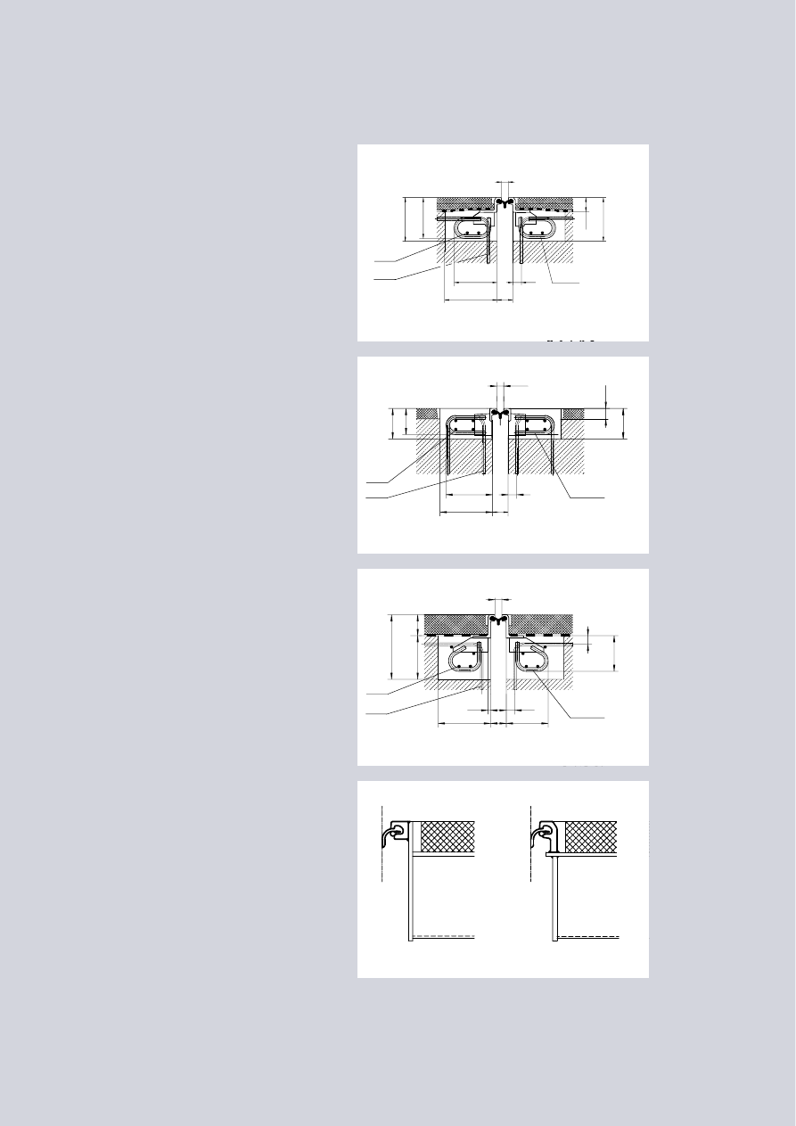
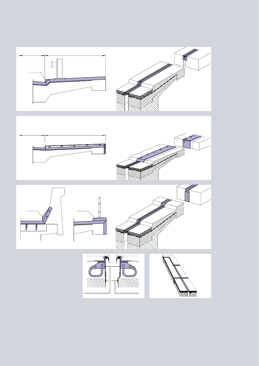
Fig.1
Should the bridge deck not allow
for a blockout depth of 300 mm,
the anchor size can be reduced
to a certain extent. This also
refers to locations where stres-
sing heads impair full size
anchors.
Fig.2
In cases where the deck slab is
extremely thin or for concrete
surfaces, a modified anchorage
will be provided. However, the
anchoring concrete must be
extended to the road surface
forming a transition strip bet-
ween the adjacent steel edge
beam
and the asphalt surface.
Fig.3
A not everyday design is the
adaption of the height of the
steel edge beams to the asphalt
surfacing which in principle can
be done for any thickness at
extra costs.
Please also refer to the page
“Joint Components”.
Fig.4
The connection to steel bridges
or else anchoring designs made
of steel to be individually solved.
Solutions that frequently appear
are shown here.
Road and Highway Bridges
Carriageway Varieties
Type D 80 with concrete transition strip
Type D 80 with adapted edge profile height (120)
Type D 80 connection to steel bridges
Type D 80 with reduced blockouts
min.
max.
0
80
Ø 20
e = 250
50
130
Ø 16
e = 200
Ø 16
240
300
50
250
250
230
var.
min.
max.
0
80
Ø 20
e = 250
50
130
Ø 16
e = 200
Ø 16
270
300
50
175
155
var.
175
min.
max.
0
80
Ø 20
e = 250
50
130
Ø 16
e = 250
Ø 16
15
300
≥50
205
370
250
≥5
0
120
240
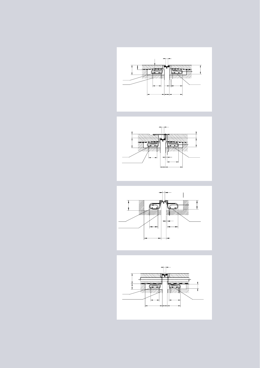
Fig.5
Standard blockout dimensions for
type D 80 in footways with water-
proofing membrane, avoiding cover
plates. Joints without cover plates
feature a more aesthetic appear-
ance and facilitate inspection and
maintenance. The open gap is safe
for pedestrians.
Please also refer to the page
“Design Varieties”.
Fig.6
D 80 joint with footway cover plate
and waterproofing membrane.
Please also refer to the page “Design
Varieties”.
Cover plates are susceptible to
corrosion and promote ingress of
water and dirt to joint underneath
preventing natural exposure of the
joint components to the weather
all year round.
Fig.7
Joint design for footways without
waterproofing membrane and with-
out cover plates. The steel edge
beams do not show the horizontal
ledge usually provided for structures
with water proofing membrane.
Please also refer to the page “Joint
Components”.
Fig.8
Where service ducts located above
the waterproofing membrane must
be considered the joint elevation
must be increased to not perforate
the membrane. Holes will be prov-
ided in the edge beams to accom-
modate the service ducts. In struc-
tures without waterproofing mem-
brane the service ducts can be
lowered in the joint location and
arranged underneath the blockout.
Road and Highway Bridges
Footway Details
Footway joint
Footway joint with cover plates
Footway joint without waterproofing membrane
Footway joint with service ducts
min.
max.
0
80
Ø 14
e = 250
50
130
Ø 16
e = 250
Ø 16
150
300
230
157
170
var.
200
30
min.
max.
0
80
Ø 14
e = 250
50
130
Ø 16; e = 200
Ø 16
150
30
300
157
170
var
.
200
var
.
min.
max.
0
80
Ø 14;
e = 250
50
130
Ø 16; e = 200
Ø 16
150
15
158
180
195
min.
max.
0
80
Ø 14
e = 250
50
130
Ø 16
e = 200
Ø 16
150
300
230
70
100
var.
200
300
70
Maurer Söhne Head Office:
P.O. Box 44 01 45, D-80750 München
Frankfurter Ring 193, D-80807 München
Telephone (49)-(89) 3 23 94-0
Fax (49)-(89) 3 23 94-306
Maurer Söhne Main Branch Office:
P.O. Box 30 04 54, D-44234 Dortmund
Westfalendamm 87, D-44141 Dortmund
Telephone (49)-(2 31) 4 34 01-0
Fax (49)-(2 31) 4 34 01-11
Maurer Söhne Subsidiary Plant:
P.O. Box 55, D-02992 Bernsdorf
Kamenzer Str. 4-6, D-02994 Bernsdorf
Telephone (49)-(3 57 23) 2 37-0
Fax (49)-(3 57 23) 2 37-20
References
Bearing in mind that the amount
of money spent on expansion
joints in bridges comes up to
approximately 1.5% of the total
structural costs only, it is certainly
short-sighted to evaluate solely the
purchase price of these important
bridge members. The initial
savings can gener-ate tremendous
costs later on, if the joint system
chosen fails.
06.97
Wyszukiwarka
Podobne podstrony:
Folder Maurer Dylatacje 2
Folder Maurer D xxxx ver D
Pliki, foldery, skroty kalwiszo Nieznany
egzamin 2007, II rok, II rok CM UMK, Giełdy, 2 rok, II rok, giełdy od Nura, fizjo, egzamin, New fold
Minerał, SGGW Inżynieria Środowiska, SEMESTR 1, Rok 1 od Anki, Geologia, geologia, Nowy folder, Geol
karta technologiczna1, Polibuda (MiBM), Semestr VI, SKOWRON, Nowy folder, VI semestr, Talar, projekt
egz fizjo, II ROK STOMATOLOGIA SUM ZABRZE, FIZJOLOGIA, FIZJOLOGIA EGZAMIN, foldery z pytaniami, egza
Bohater Romantyczny, Dostępne pliki i foldery - hasło to folder, #Pomoce szkolne, JĘZYK POLSKI - GOT
3 c) Mój kolega inaczej się porusza karta pracy nr 3, FOLDER I Mój kolega inaczej się porusza
ściąga 4, Gospodarka wodno ściekowa, Nowy folder (3), Gorący, Ściąga gorący
nawiązanie współpracy, II rok II semestr, BWC, org pracy biurowej, Nowy folder
Urządzenia 101 - parametry łączników protokół (tylko dla ZAO, Politechnika Lubelska, Studia, semestr
Sieci 9, Politechnika Lubelska, Studia, semestr 5, Sem V, Nowy folder
Teoria ster. 4, Politechnika Lubelska, Studia, semestr 5, Sem V, Nowy folder
Oświetlenie 11, Politechnika Lubelska, Studia, semestr 5, Sem V, Nowy folder
więcej podobnych podstron