
DAEWOO M-150 BL2
SECTION 4A
HYDRAULIC BRAKES
CAUTION: Disconnect the negative battery cable before removing or installing any electrical unit or when a
tool or equipment could easily come in contact with exposed electrical terminals. Disconnecting this cable
will help prevent personal injury and damage to the vehicle. The ignition must also be in B unless otherwise
noted.
TABLE OF CONTENTS
Description and Operation
4A-2
. . . . . . . . . . . . . . . . . .
Warning Lamp Operation
4A-2
. . . . . . . . . . . . . . . . . . .
Component Locator
4A-3
. . . . . . . . . . . . . . . . . . . . . . . .
Brake System (Non-ABS)
4A-3
. . . . . . . . . . . . . . . . . .
Diagnostic Information and Procedures
4A-4
. . . . .
Brake System Testing
4A-4
. . . . . . . . . . . . . . . . . . . . . .
Brake Hose Inspection
4A-4
. . . . . . . . . . . . . . . . . . . . .
Warning Lamp Operation
4A-5
. . . . . . . . . . . . . . . . . . .
Brake System Fault
4A-5
. . . . . . . . . . . . . . . . . . . . . . . .
Manual Bleeding the Brakes
4A-6
. . . . . . . . . . . . . . . .
Pedal Travel Check
4A-6
. . . . . . . . . . . . . . . . . . . . . . . .
Brake Pedal Free Play Inspection
4A-7
. . . . . . . . . . .
Repair Instructions
4A-8
. . . . . . . . . . . . . . . . . . . . . . . . .
On-Vehicle Service
4A-8
. . . . . . . . . . . . . . . . . . . . . . . . . .
Brake Hose (Front)
4A-8
. . . . . . . . . . . . . . . . . . . . . . . .
Brake Hose (Rear)
4A-9
. . . . . . . . . . . . . . . . . . . . . . . .
Stoplamp Switch
4A-9
. . . . . . . . . . . . . . . . . . . . . . . . . .
Brake Pedal
4A-10
. . . . . . . . . . . . . . . . . . . . . . . . . . . . .
Specifications
4A-13
. . . . . . . . . . . . . . . . . . . . . . . . . . . .
General Specifications
4A-13
. . . . . . . . . . . . . . . . . . . .
Fastener Tightening Specifications
4A-13
. . . . . . . . . .
Schematic and Routing Diagrams
4A-14
. . . . . . . . . .
Brake Lamp Warning Circuit
4A-14
. . . . . . . . . . . . . . .
Stoplamp Switch Circuit
4A-14
. . . . . . . . . . . . . . . . . . .
4A – 2 HYDRAULIC BRAKES
DAEWOO M-150 BL2
DESCRIPTION AND OPERATION
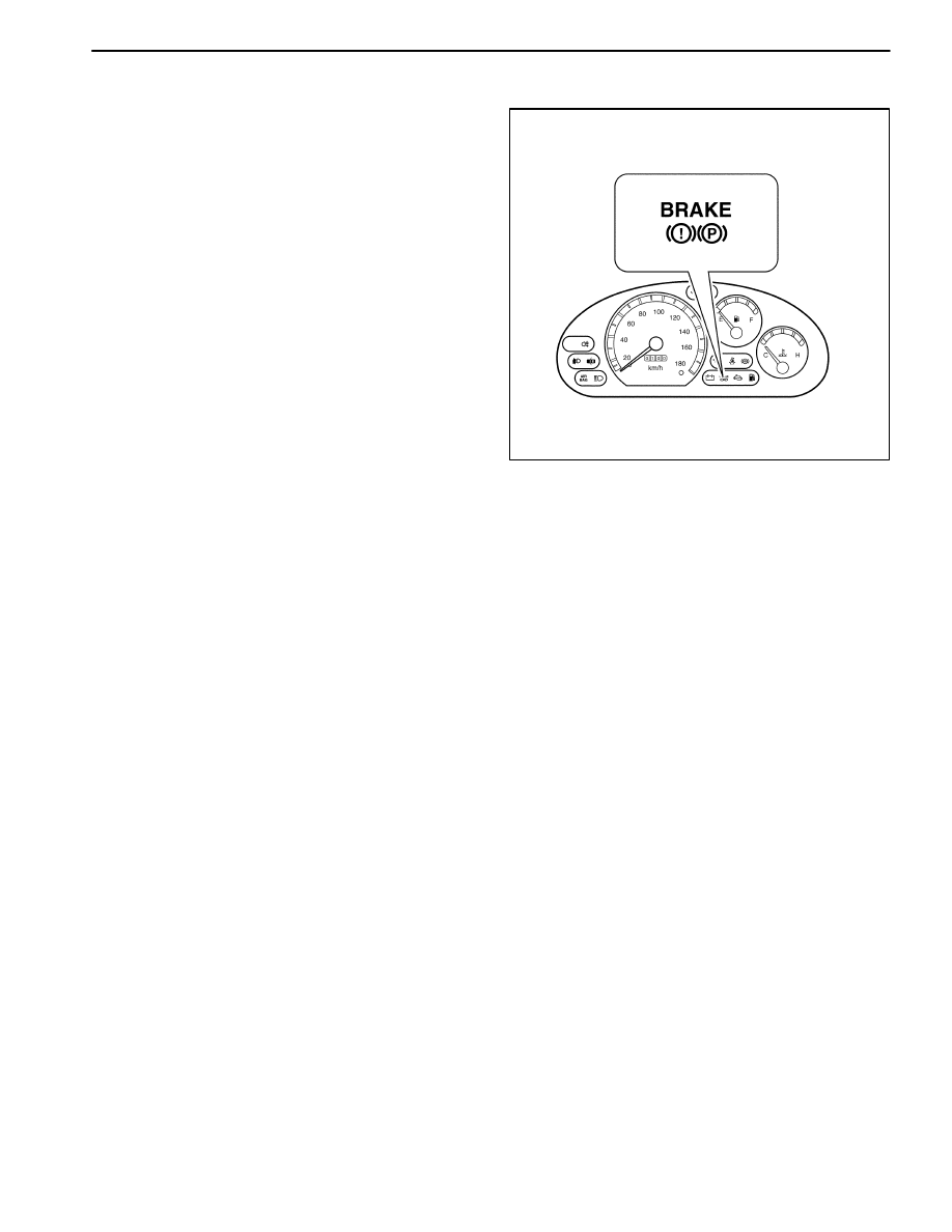
WARNING LAMP OPERATION
This brake system uses a BRAKE warning lamp located
in the instrument panel cluster. When the ignition switch
is in the III position, the BRAKE warning lamp should il-
luminate. It should go off when the ignition switch return
to II position. The following conditions will activate the
BRAKE warning lamp.
D
The lamp should be on whenever the parking brake
applied and the ignition switch is in the II position.
D
A low fluid level in the master cylinder will turn the
BRAKE warning lamp on.
D17A007A
HYDRAULIC BRAKES 4A – 3
DAEWOO M-150 BL2
COMPONENT LOCATOR
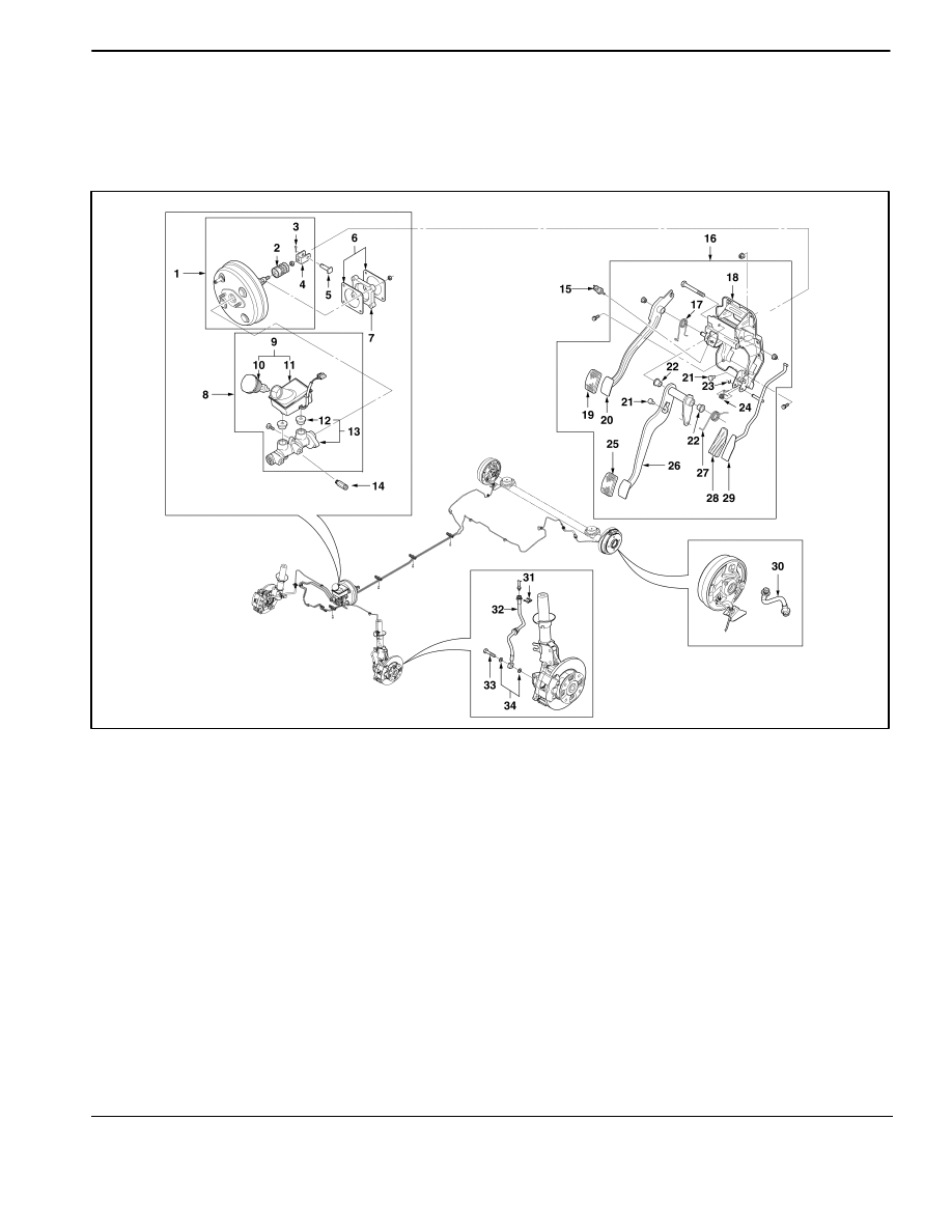
BRAKE SYSTEM (NON–ABS)
(Left–Hand Drive Shown, Right–Hand Drive Similar)
MAB4A001
1. Power Booster
2. Power Booster Boot
3. Cotter Pin
4. Clevis
5. Clevis Pin
6. Packing
7. Spacer
8. Master Cylinder Assembly
9. Fluid Reservoir Assembly
10. Reservoir Cap
11. Reservoir
12. Grommet Seal
13. Master Cylinder
14. Proportioning Valve
15. Stoplamp Switch
16. Brake Pedal Assembly
17. Clutch Pedal Spring
18. Pedal Bracket Assembly
19. Clutch Pedal Pad
20. Clutch Pedal
21. Cushion
22. Bushing
23. Retaining Ring
24. Spring
25. Brake Pedal Pad
26. Brake Pedal
27. Brake Pedal Spring
28. Accelator Pedal Pad
29. Accelator Pedal
30. Rear Drum Brake Hose
31. E Ring
32. Front Disc Brake Hose
33. Brake Hose Coupling Bolt
34. Plain Washer

4A – 4 HYDRAULIC BRAKES
DAEWOO M-150 BL2
DIAGNOSITIC INFORMATION AND PROCEDURES
BRAKE SYSTEM TESTING
(Left–Hand Drive Shown, Right–Hand
Drive Similar)
Brakes should be tested on a dry, clean, reasonably
smooth and level roadway. A true test of brake perfor-
mance cannot be made if the roadway is wet, greasy, or
covered with loose dirt whereby all tires do not grip the
road equally. Testing will also be adversely affected if the
roadway is crowned so as to throw the weight so roughly
that the wheels tend to bounce.
Test the brakes at different vehicle speeds with both light
and heavy pedal pressure; however, avoid locking the
brakes and sliding the tires. Locked brakes and sliding
tires do not indicate brake efficiency since heavily
braked, but turning, wheels will stop the vehicle in less
distance than locked brakes. More tire-to-road friction is
present with a heavily braked, turning tire than with a
sliding tire.
Because of the high deceleration capability, a firmer
pedal may be felt at higher deceleration levels.
There are three major external conditions that affect
brake performance:
D
Tires having unequal contact and grip of the road will
cause unequal braking. Tires must be equally in-
flated, and the tread pattern of the right and the left
tires must be approximately equal.
D
Unequal loading of the vehicle can affect the brake
performance since the most heavily loaded wheels
require more braking power, and thus more braking
effort, than the others.
D
Misalignment of the wheels, particularly conditions of
excessive camber and caster, will cause the brakes
to pull to one side.
To check for brake fluid leaks, hold constant foot pres-
sure on the pedal with the engine running at idle and the
shift lever in NEUTRAL. If the pedal gradually falls away
with the constant pressure, the hydraulic system may be
leaking. Perform a visual check to confirm any sus-
pected leaks.
Check the master cylinder fluid level. While a slight drop
in the reservoir level results from normal lining wear, an
abnormally low level indicates a leak in the system. The
hydraulic system may be leaking either internally or ex-
ternally. Refer to the procedure below to check the mas-
ter cylinder. Also, the system may appear to pass this
test while still having a slight leak. If the fluid level is nor-
mal, check the vacuum booster pushrod length. If an in-
correct pushrod length is found, adjust or replace the
rod.
Check the master cylinder using the following proce-
dure:
D
Check for a cracked master cylinder casting or brake
fluid leaking around the master cylinder. Leaks are in-
dicated only if there is at least one drop of fluid. A
damp condition is not abnormal.
D
Check for a binding pedal linkage and for an incorrect
pushrod length. If both of these parts are in satisfac-
tory condition, disassemble the master cylinder and
check for an elongated or swollen primary cylinder or
piston seals. If swollen seals are found, substandard
or contaminated brake fluid should be suspected. If
contaminated brake fluid is found, all the components
should be disassembled and cleaned, and all the rub-
ber components should be replaced. All of the pipes
must also be flushed.
Improper brake fluid, or mineral oil or water in the fluid,
may cause the brake fluid to boil or cause deterioration
of the rubber components. If the primary piston cups in
the master cylinder are swollen, then the rubber parts
have deteriorated. This deterioration may also be evi-
denced by swollen wheel cylinder piston seals on the
drum brake wheels.
If rubber deterioration is evident, disassemble all the hy-
draulic parts and wash the parts with alcohol. Dry these
parts with compressed air before reassembly to keep al-
cohol out of the system. Replace all the rubber parts in
the system, including the hoses. Also, when working on
the brake mechanisms, check for fluid on the linings. If
excessive fluid is found, replace the linings.
If the master cylinder piston seals are in satisfactory
condition, check for leaks or excessive heat conditions.
If these conditions are not found, drain the fluid, flush the
master cylinder with brake fluid, refill the master cylin-
der, and bleed the system. Refer to “Manual Bleeding
the Brakes” in this section.
BRAKE HOSE INSPECTION
The hydraulic brake hoses should be inspected at least
twice a year. The brake hose assembly should be
checked for road hazard damage, cracks, chafing of the
outer cover, and for leaks or blisters. Inspect the hoses
for proper routing and mounting. A brake hose that rubs
on a suspension component will wear and eventually
fail. A light and a mirror may be needed for an adequate
inspection. If any of the above conditions are observed
on the brake hose, adjust or replace the hose as neces-
sary.

HYDRAULIC BRAKES 4A – 5
DAEWOO M-150 BL2
WARNING LAMP OPERATION
This brake system uses a BRAKE warning lamp located
in the instrument panel cluster. When the ignition switch
is in the
III
position, the BRAKE warning lamp should
glow and then go OFF when the ignition switch returns
to the
II
position.
The following conditions will activate the BRAKE lamp:
D
Parking brake applied. The light should be on when-
ever the parking brake is applied and the ignition
switch is
II
.
D
Low fluid level. A low fluid level in the master cylinder
will turn the BRAKE lamp ON.
BRAKE SYSTEM FAULT
ÁÁÁÁÁÁÁÁÁÁ
ÁÁÁÁÁÁÁÁÁÁ
Condition
ÁÁÁÁÁÁÁÁÁÁÁÁÁ
ÁÁÁÁÁÁÁÁÁÁÁÁÁ
Probable cause
ÁÁÁÁÁÁÁÁÁÁÁÁÁÁ
ÁÁÁÁÁÁÁÁÁÁÁÁÁÁ
Correction
Brake Warning Lamp ON
D
Brake fluid leaks.
D
Repair the leaks or add th fluid.
D
Parking brake switch shorted to
ground.
D
Repair the short ground.
D
Faulty the fluid level sensor.
D
Replace the sensor.
Stoplamp ON
D
Faulty the stoplamp switch.
D
Replace the stoplamp switch.
D
Push rod length is short.
D
Adjust the push rod length of the
power booster.
D
Stoplamp switch circuit shorted to
battery.
D
Repair or Replace the wiring harness.
Poor Braking
D
Brake fluid lacks or leaks.
D
Repair the leaks or add the fluid.
D
Brake fluid contamination.
D
Replace the fluid.
D
Air in the brake system.
D
Bleed the brake system.
D
Damaged brake lines.
D
Replace the brake lines.
D
Damaged vacuum hose or faulty
check valve.
D
Replace the vacuum hose or check
value.
Dragging Brake
D
No free play at the brake pedal.
D
Adjust the free play.
D
Weakened the brake pedal return
spring.
D
Replace the return spring.
D
Faulty master cylinder.
D
Replace the master cylinder.
D
Air in the brake system.
D
Bleed the brake system.
Pedal Over Stroke
D
Brake fluid lacks or leaks.
D
Repair the leaks or add the fluid.
D
Poor adjustment of the brake pedal
free play.
D
Adjust the push rod length of the
power booster.
4A – 6 HYDRAULIC BRAKES
DAEWOO M-150 BL2
MANUAL BLEEDING THE BRAKES
Important: The bleeding sequence is as follows; right
rear, left rear, right front, and left front.
Important: Check the fluid level and add the fluid during
the bleeding operation.
1. Raise the vehicle.
2. Remove the bleeder screw and cap.
D17B703B
3. Attach a transparent tube over the valve. Allow the
tube to hang submerged in brake fluid in a transpar-
ent container.
D107A303
4. Slowly push the brake pedal several times and hold
the brake pedal.
5. Tighten the bleeder screw after loosening the bleeder
screw and draining the fluid.
Caution: Hold the brake pedal until tightening the
bleeder screw.
6. Repeat the step 5, 6 until all the air is removed.
7. Check the leaks for the bleeder screw.
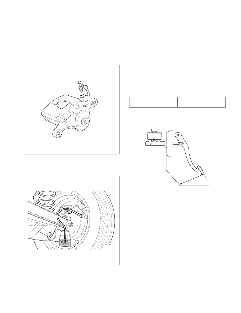
PEDAL TRAVEL CHECK
1. Start the engine.
2. Push the pedal three times.
3. With brake pedal depressed with a about 30Kg (66.15
lb) load, measure the clearance between the pedal
pad and the lower dash panel.
Unit : mm (in.)
ÁÁÁÁÁÁÁÁÁ
ÁÁÁÁÁÁÁÁÁ
ÁÁÁÁÁÁÁÁÁ
Specification
ÁÁÁÁÁÁÁÁÁ
ÁÁÁÁÁÁÁÁÁ
ÁÁÁÁÁÁÁÁÁ
60 (2.36)
D107A304
4. If clearance is less than 60mm (2.36 in.), the most
possible cause is either rear drum brake shoes are
worn out beyond the specification value or air is in
lines. Clearance still remains less than 60mm (2.36
in.) even after replacement of brake shoes and bleed-
ing of the brake system, other possible but infrequent
cause is malfunction of rear drum brake shoe adjust-
ers or booster push rod length out of adjustment.
5. Automatic clearance adjuster check is performed af-
ter removing brake drums. If the faulty is found, repair
or replace it.
HYDRAULIC BRAKES 4A – 7
DAEWOO M-150 BL2
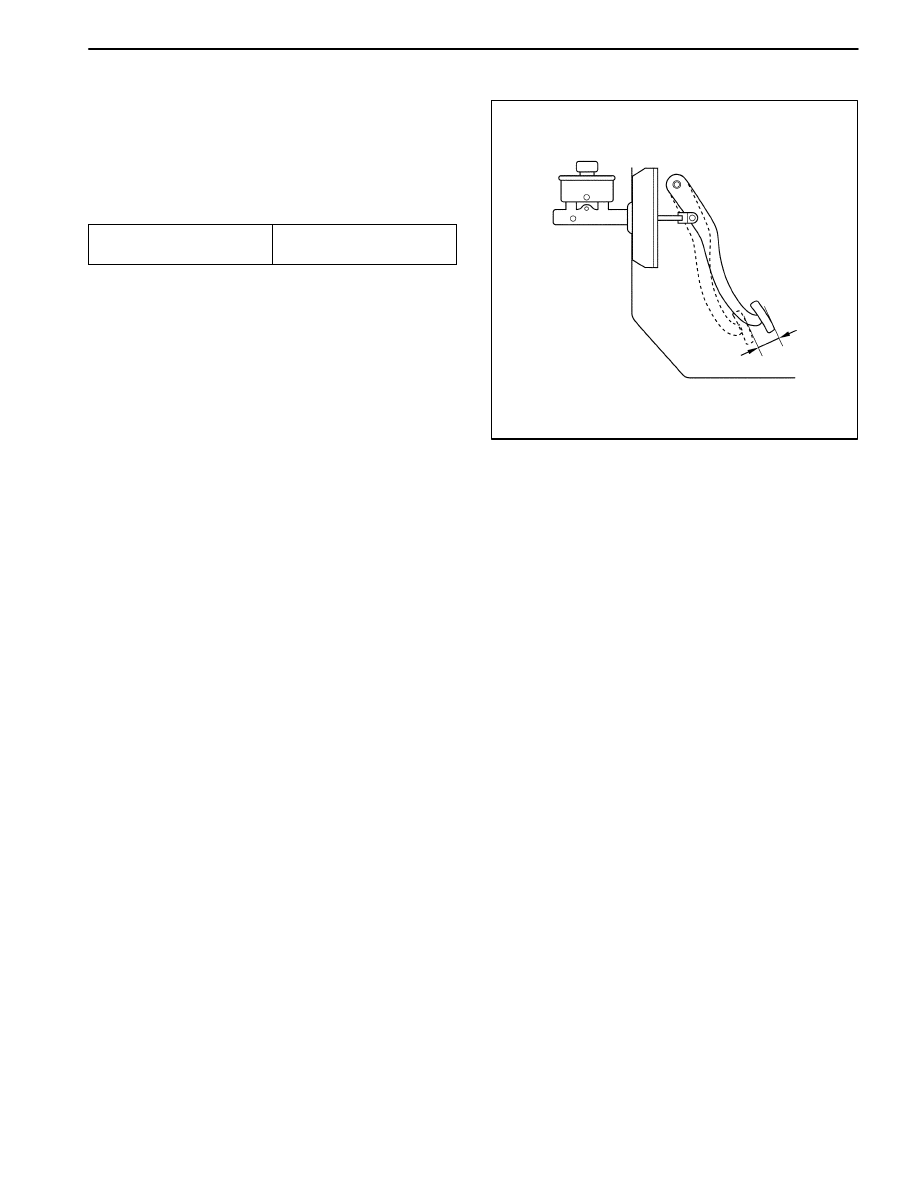
BRAKE PEDAL FREE PLAY
INSPECTION
1. Push the brake pedal several times to discharge the
vacuum of the power booster.
2. Measure the pedal movement until the hardness is
felt when pushing the brake pedal by hand.
Unit : mm (in.)
ÁÁÁÁÁÁÁÁÁ
ÁÁÁÁÁÁÁÁÁ
ÁÁÁÁÁÁÁÁÁ
Specification
ÁÁÁÁÁÁÁÁÁ
ÁÁÁÁÁÁÁÁÁ
ÁÁÁÁÁÁÁÁÁ
6–10 (0.24–0.31)
3. Brake pedal free play can not be adjusted.
D107A305
4A – 8 HYDRAULIC BRAKES
DAEWOO M-150 BL2
REPAIR INSTRUCTIONS
ON–VEHICLE SERVICE
D107A528
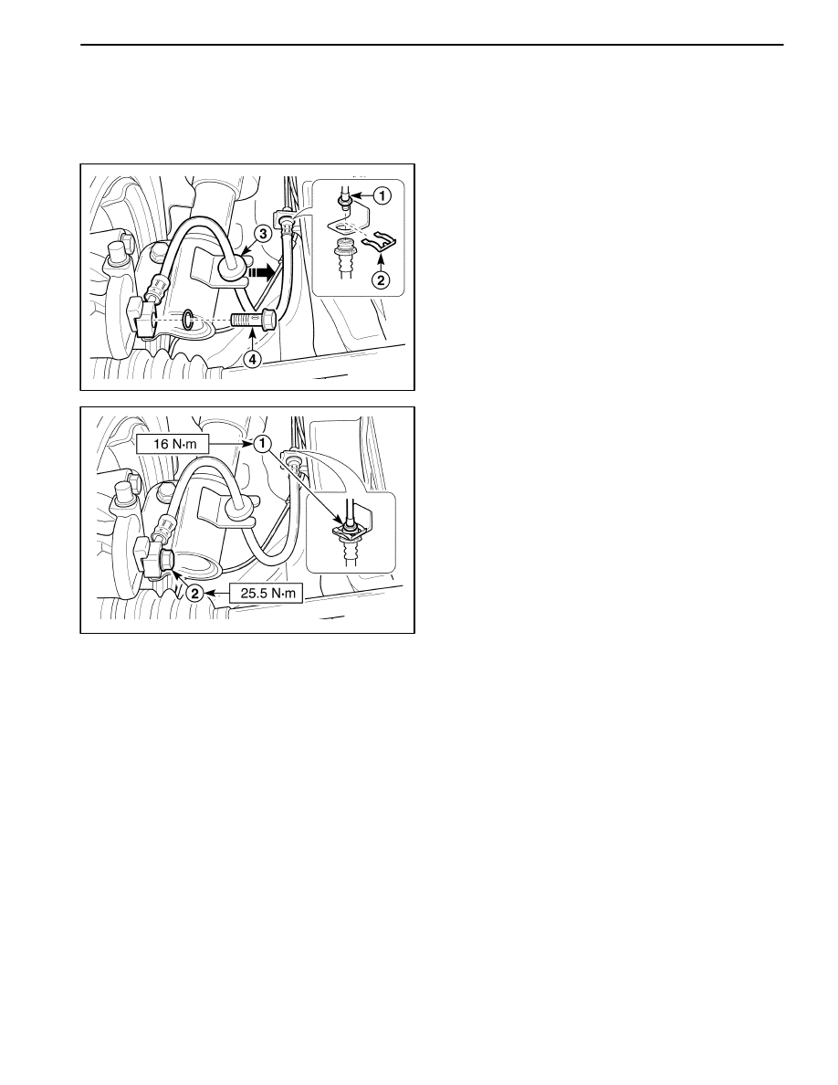
BRAKE HOSE (FRONT)
Removal Procedure
1. Remove the wheels. Refer to Section 2E, Tires and
Wheels.
2. Remove the brake hose.
D
Remove the fitting (1).
D
Remove the E–ring retainer (2).
D
Disconnect the brake hose mounting from the strut
(3).
D
Remove the coupling bolt (4).
D
Plug the opening in the brake pipe and caliper to
prevent fluid loss or contamination.
D17A529B
Installation Procedure
1. Connect the brake lines to the brake hose (1).
Tighten
Tighten the brake pipe–to–hose fitting to 16 N
S
m (12
lb-ft).
2. Install the brake hose coupling bolt (2).
Tighten
Tighten the bolt to 25.5 N
S
m (19.1 lb-ft).
Important: Use only Daewoo recommended brake
fluid.
3. Bleed the brake system. Refer to “Manual Bleeding
the Brakes” in this section.
4. Check the brake system for leaks.
5. Install the wheels. Refer to Section 2E, Tires and
Wheels.
HYDRAULIC BRAKES 4A – 9
DAEWOO M-150 BL2
D107A530
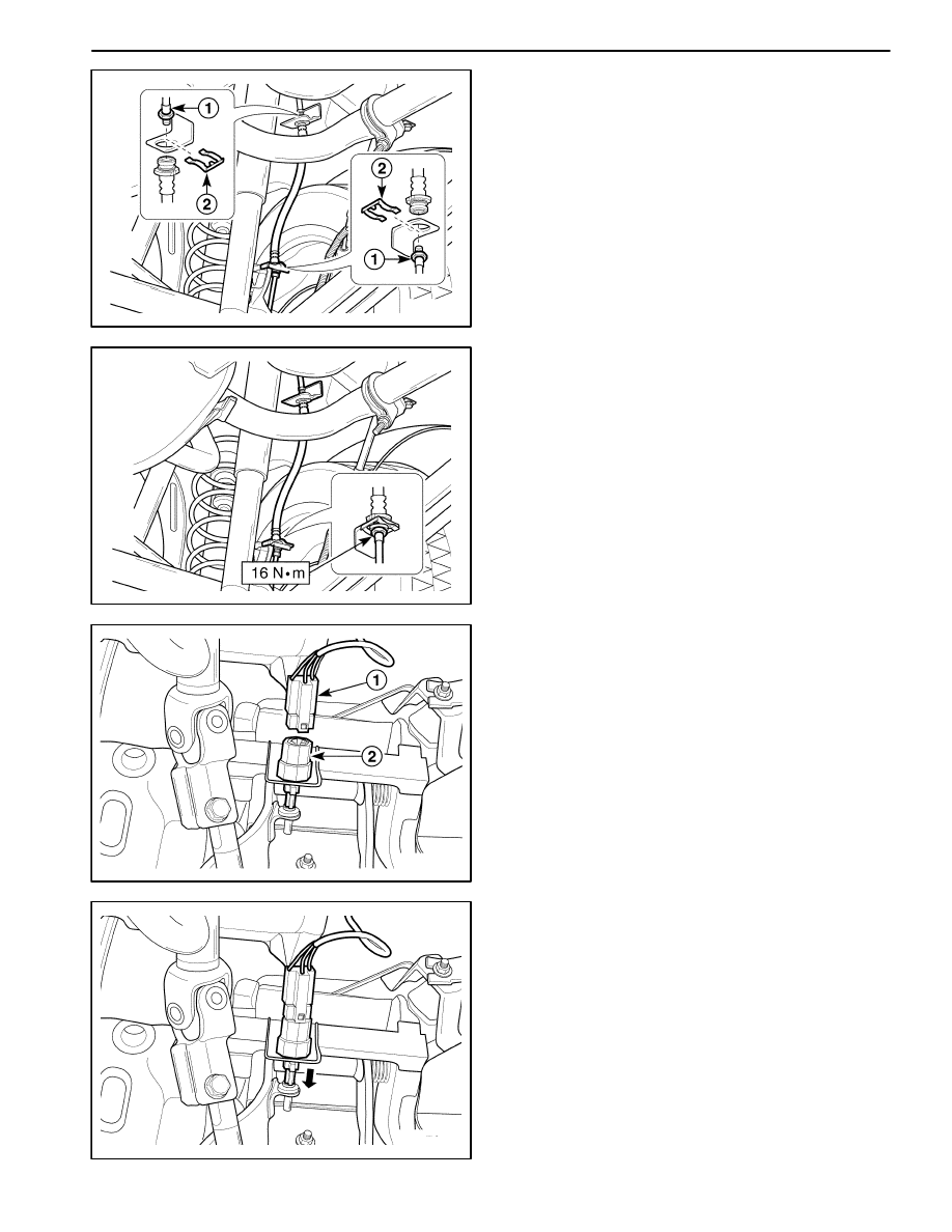
BRAKE HOSE (REAR)
Removal Procedure
1. Remove the wheels. Refer to Section 2E, Tires and
Wheels.
2. Remove the brake hose.
D
Remove the fittings (1).
D
Remove the E–rings (2).
D
Plug the opening in the brake pipe to prevent fluid
loss or contamination.
D17A531A
Installation Procedure
1. Connect the brake lines to the brake hose.
2. Install the fitting and E–rings.
Tighten
Tighten the fitting to 16 N
S
m (12 lb-ft).
Important: Use only Daewoo recommended brake fluid.
3. Bleed the brake system. Refer to “Manual Bleeding
the Brakes” in this section.
4. Check the brake system for leaks.
5. Install the wheels. Refer to Section 2E, Tires and
Wheels.
D107A523
STOPLAMP SWITCH
(Left–Hand Drive Shown, Right–Hand
Drive Similar)
Removal Procedure
1. Disconnect the negative battery cable.
2. Remove the stoplamp switch.
D
Disconnect the connector (1).
D
Turn the stoplamp switch (2).
D107A524
Installation Procedure
1. Install the stoplamp switch.
2. Connect the electrical connector.
3. Connect the negative battery cable.
Important: After installing the stoplamp switch, pull the
lever completely.
4A – 10 HYDRAULIC BRAKES
DAEWOO M-150 BL2
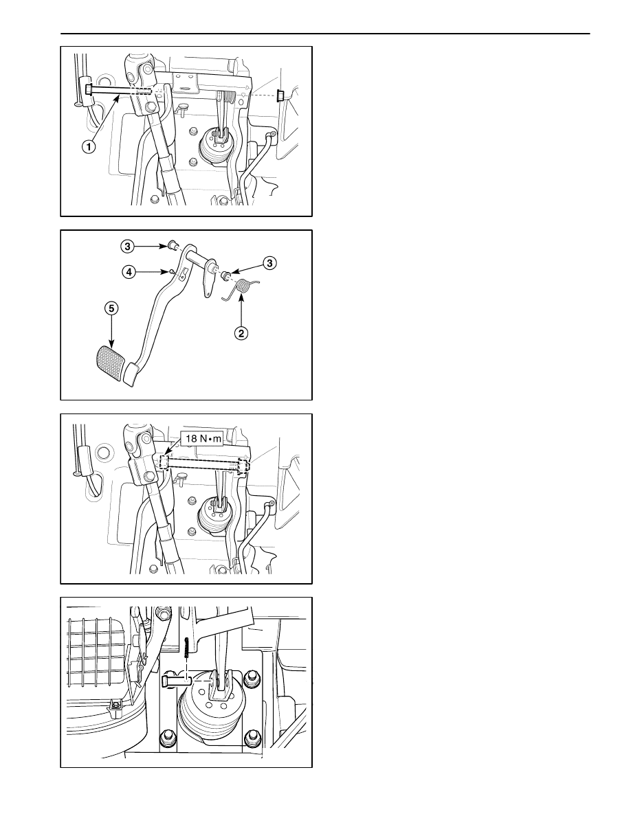
D107A525
BRAKE PEDAL
(LEFT–HAND DRIVE)
Removal Procedure
1. Remove the stoplamp switch. Refer to “Stoplamp
Switch” in this section.
2. Disconnect the brake pedal from the power booster.
Refer to Section 4C, Power Booster.
3. Remove the brake pedal.
D
Remove the bolt (1).
D107A526
D
Remove the brake pedal spring (2).
D
Remove the bushing (3).
D
Remove the cushion (4).
D
Remove the brake pedal pad (5).
D17A527A
Installation Procedure
1. Install the pad to the brake pedal.
2. Install the brake pedal with spring, bushing, and cush-
ion.
3. Connect the brake pedal to the power booster.
Tighten
Tighten the brake pedal–to–pedal bracket bolt to 18
N
S
m (13 lb-ft).
4. Install the stoplamp switch. Refer to “Stoplamp
Switch” in this section.
D24C001A
BRAKE PEDAL
(RIGHT–HAND DRIVE)
Removal Procedure
1. Remove the instrument panel assembly. Refer to
Section 9E, Instrument/Driver Information.
2. Disconnect the brake pedal rod from the power
booster. Refer to Section 4C, Power Booster.
HYDRAULIC BRAKES 4A – 11
DAEWOO M-150 BL2
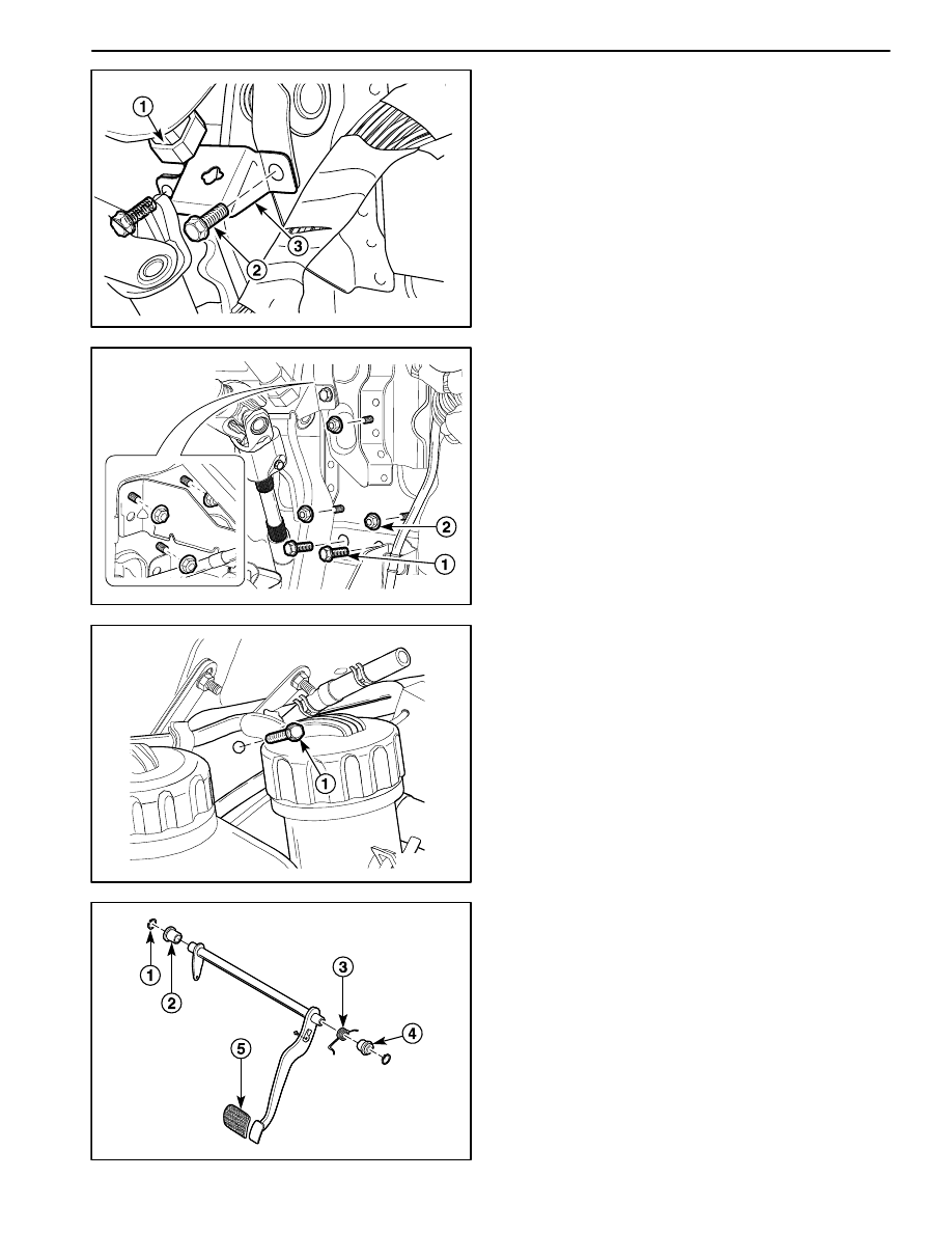
D24D001
3. Remove the stoplamp switch.
D
Remove the stoplamp switch (1).
D
Remove the bolts (2).
D
Remove the stoplamp switch bracket (3).
D24D002
4. Remove the bolts mounting brake pedal bracket (1).
5. Remove the nuts mounting brake pedal bracket (2).
D24D003
6. Remove the canister. Refer to Section 1F, Engine
Controls.
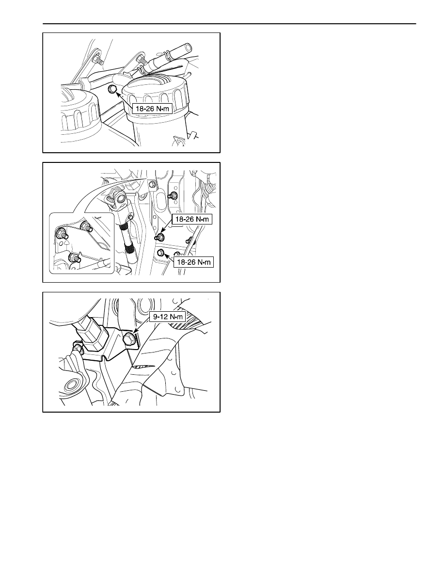
7. Remove the bolt mounting brake pedal bracket in the
engine compartment (1).
D24D004
8. Remove the brake pedal.
D
Remove the snap rings (1).
D
Remove the bushings (2).
D
Remove the brake pedal spring (3).
D
Remove the cushion (4).
D
Remove the brake pedal pad (5).
4A – 12 HYDRAULIC BRAKES
DAEWOO M-150 BL2
D24D005
Installation Procedure
1. Install the brake pedal with pad, spring, bushings, and
cushion.
2. Install the bolt mounting brake pedal bracket in the
engine compartment.
Tighten
Tighten the bolt to 18–26 N
S
m (13–20 lb-ft).
3. Install the canister. Refer to Section 1F, Engine Con-
trols.
D24D006
4. Install the brake pedal with the snap rings.
5. Install the bolts and nuts mounting brake pedal brack-
et.
Tighten
D
Tighten the bolts mounting brake pedal bracket to
18–26 N
S
m (13–20 lb-ft).
D
Tighten the nuts mounting brake pedal bracket to
18–26 N
S
m (13–20 lb-ft).
D24D007
6. Install the stoplamp switch with the bracket and the
bolts.
Tighten
Tighten the mounting bolts to 9–12 N
S
m (80–106 lb-
in.)
7. Connect the brake pedal rod to the power booster.
Refer to Section 4C, Power Booster.
8. Install the instrument panel assembly. Refer to Sec-
tion 9E, Instrument/Driver Information.

HYDRAULIC BRAKES 4A – 13
DAEWOO M-150 BL2
SPECIFICATIONS
GENERAL SPECIFICATIONS
ÁÁÁÁÁÁÁÁÁÁÁÁÁÁÁÁÁÁÁÁ
ÁÁÁÁÁÁÁÁÁÁÁÁÁÁÁÁÁÁÁÁ
ÁÁÁÁÁÁÁÁÁÁÁÁÁÁÁÁ
ÁÁÁÁÁÁÁÁÁÁÁÁÁÁÁÁ
0.8 SOHC Engine
ÁÁÁÁÁÁÁÁÁÁÁÁÁÁÁÁÁÁÁÁ
ÁÁÁÁÁÁÁÁÁÁÁÁÁÁÁÁÁÁÁÁ
Application
ÁÁÁÁÁÁÁÁ
ÁÁÁÁÁÁÁÁ
Millimeters
ÁÁÁÁÁÁÁÁÁ
ÁÁÁÁÁÁÁÁÁ
Inches
ÁÁÁÁÁÁÁÁÁÁÁÁÁÁÁÁÁÁÁÁ
ÁÁÁÁÁÁÁÁÁÁÁÁÁÁÁÁÁÁÁÁ
ÁÁÁÁÁÁÁÁÁÁÁÁÁÁÁÁÁÁÁÁ
ÁÁÁÁÁÁÁÁÁÁÁÁÁÁÁÁÁÁÁÁ
Brake Drums:
Inside Diameter
Maximum Rebore Diameter
Out-of-Round
ÁÁÁÁÁÁÁÁ
ÁÁÁÁÁÁÁÁ
ÁÁÁÁÁÁÁÁ
ÁÁÁÁÁÁÁÁ
180
182
0.04
ÁÁÁÁÁÁÁÁÁ
ÁÁÁÁÁÁÁÁÁ
ÁÁÁÁÁÁÁÁÁ
ÁÁÁÁÁÁÁÁÁ
7.09
7.17
0.0016
ÁÁÁÁÁÁÁÁÁÁÁÁÁÁÁÁÁÁÁÁ
ÁÁÁÁÁÁÁÁÁÁÁÁÁÁÁÁÁÁÁÁ
ÁÁÁÁÁÁÁÁÁÁÁÁÁÁÁÁÁÁÁÁ
ÁÁÁÁÁÁÁÁÁÁÁÁÁÁÁÁÁÁÁÁ
ÁÁÁÁÁÁÁÁÁÁÁÁÁÁÁÁÁÁÁÁ
Brake Rotors:
Discard Thickness
Lateral Runout (Installed)
Rotor Diameter
Rotor Thickness (New)
ÁÁÁÁÁÁÁÁ
ÁÁÁÁÁÁÁÁ
ÁÁÁÁÁÁÁÁ
ÁÁÁÁÁÁÁÁ
ÁÁÁÁÁÁÁÁ
10
0.05
236
12.7
ÁÁÁÁÁÁÁÁÁ
ÁÁÁÁÁÁÁÁÁ
ÁÁÁÁÁÁÁÁÁ
ÁÁÁÁÁÁÁÁÁ
ÁÁÁÁÁÁÁÁÁ
0.4
0.002
9.3
0.5
ÁÁÁÁÁÁÁÁÁÁÁÁÁÁÁÁÁÁÁÁ
ÁÁÁÁÁÁÁÁÁÁÁÁÁÁÁÁÁÁÁÁ
Master Cylinder:
Bore Diameter
ÁÁÁÁÁÁÁÁ
ÁÁÁÁÁÁÁÁ
20.64
ÁÁÁÁÁÁÁÁÁ
ÁÁÁÁÁÁÁÁÁ
0.81
ÁÁÁÁÁÁÁÁÁÁÁÁÁÁÁÁÁÁÁÁ
ÁÁÁÁÁÁÁÁÁÁÁÁÁÁÁÁÁÁÁÁ
ÁÁÁÁÁÁÁÁÁÁÁÁÁÁÁÁÁÁÁÁ
Caliper:
Piston Diameter
ÁÁÁÁÁÁÁÁ
ÁÁÁÁÁÁÁÁ
ÁÁÁÁÁÁÁÁ
48
ÁÁÁÁÁÁÁÁÁ
ÁÁÁÁÁÁÁÁÁ
ÁÁÁÁÁÁÁÁÁ
1.89
ÁÁÁÁÁÁÁÁÁÁÁÁÁÁÁÁÁÁÁÁ
ÁÁÁÁÁÁÁÁÁÁÁÁÁÁÁÁÁÁÁÁ
Wheel Cylinder Diameter:
ÁÁÁÁÁÁÁÁ
ÁÁÁÁÁÁÁÁ
17.46
ÁÁÁÁÁÁÁÁÁ
ÁÁÁÁÁÁÁÁÁ
0.69
ÁÁÁÁÁÁÁÁÁÁÁÁÁÁÁÁÁÁÁÁ
ÁÁÁÁÁÁÁÁÁÁÁÁÁÁÁÁÁÁÁÁ
ÁÁÁÁÁÁÁÁÁÁÁÁÁÁÁÁÁÁÁÁ
ÁÁÁÁÁÁÁÁÁÁÁÁÁÁÁÁÁÁÁÁ
Brake Pedal:
Free Play
Height
Stroke
ÁÁÁÁÁÁÁÁ
ÁÁÁÁÁÁÁÁ
ÁÁÁÁÁÁÁÁ
ÁÁÁÁÁÁÁÁ
6 – 10
200
30
ÁÁÁÁÁÁÁÁÁ
ÁÁÁÁÁÁÁÁÁ
ÁÁÁÁÁÁÁÁÁ
ÁÁÁÁÁÁÁÁÁ
0.24 – 0.31
7.87
1.18
ÁÁÁÁÁÁÁÁÁÁÁÁ
ÁÁÁÁÁÁÁÁÁÁÁÁ
ÁÁÁÁÁÁÁÁÁ
ÁÁÁÁÁÁÁÁÁ
Type
ÁÁÁÁÁÁÁÁÁÁÁÁÁÁÁÁ
ÁÁÁÁÁÁÁÁÁÁÁÁÁÁÁÁ
DOT–3 or DOT–4
ÁÁÁÁÁÁÁÁÁÁÁÁ
ÁÁÁÁÁÁÁÁÁÁÁÁ
Brake Fluid
ÁÁÁÁÁÁÁÁÁ
ÁÁÁÁÁÁÁÁÁ
Capacity
ÁÁÁÁÁÁÁÁÁÁÁÁÁÁÁÁ
ÁÁÁÁÁÁÁÁÁÁÁÁÁÁÁÁ
0.45 L (0.48 qt.)
FASTENER TIGHTENING SPECIFICATIONS
ÁÁÁÁÁÁÁÁÁÁÁÁÁÁÁÁÁÁ
ÁÁÁÁÁÁÁÁÁÁÁÁÁÁÁÁÁÁ
ÁÁÁÁÁÁÁÁÁÁÁÁÁÁÁÁÁÁ
Application
ÁÁÁÁÁÁÁ
ÁÁÁÁÁÁÁ
ÁÁÁÁÁÁÁ
N
S
m
ÁÁÁÁÁÁ
ÁÁÁÁÁÁ
ÁÁÁÁÁÁ
Lb-Ft
ÁÁÁÁÁÁÁ
ÁÁÁÁÁÁÁ
ÁÁÁÁÁÁÁ
Lb-In
ÁÁÁÁÁÁÁÁÁÁÁÁÁÁÁÁÁÁ
ÁÁÁÁÁÁÁÁÁÁÁÁÁÁÁÁÁÁ
Brake Pipe Fittings
ÁÁÁÁÁÁÁ
ÁÁÁÁÁÁÁ
16
ÁÁÁÁÁÁ
ÁÁÁÁÁÁ
12
ÁÁÁÁÁÁÁ
ÁÁÁÁÁÁÁ
–
ÁÁÁÁÁÁÁÁÁÁÁÁÁÁÁÁÁÁ
ÁÁÁÁÁÁÁÁÁÁÁÁÁÁÁÁÁÁ
Front Brake Hose-to-Caliper Bolt
ÁÁÁÁÁÁÁ
ÁÁÁÁÁÁÁ
25.5
ÁÁÁÁÁÁ
ÁÁÁÁÁÁ
19.1
ÁÁÁÁÁÁÁ
ÁÁÁÁÁÁÁ
–
ÁÁÁÁÁÁÁÁÁÁÁÁÁÁÁÁÁÁ
ÁÁÁÁÁÁÁÁÁÁÁÁÁÁÁÁÁÁ
ÁÁÁÁÁÁÁÁÁÁÁÁÁÁÁÁÁÁ
Brake Pedal–to–Pedal Bracket Hex Bolt
ÁÁÁÁÁÁÁ
ÁÁÁÁÁÁÁ
ÁÁÁÁÁÁÁ
18
ÁÁÁÁÁÁ
ÁÁÁÁÁÁ
ÁÁÁÁÁÁ
13
ÁÁÁÁÁÁÁ
ÁÁÁÁÁÁÁ
ÁÁÁÁÁÁÁ
–
ÁÁÁÁÁÁÁÁÁÁÁÁÁÁÁÁÁÁ
ÁÁÁÁÁÁÁÁÁÁÁÁÁÁÁÁÁÁ
Brake Pedal Bracket Mounting Bolts
ÁÁÁÁÁÁÁ
ÁÁÁÁÁÁÁ
18 – 26
ÁÁÁÁÁÁ
ÁÁÁÁÁÁ
13 – 20
ÁÁÁÁÁÁÁ
ÁÁÁÁÁÁÁ
–
ÁÁÁÁÁÁÁÁÁÁÁÁÁÁÁÁÁÁ
ÁÁÁÁÁÁÁÁÁÁÁÁÁÁÁÁÁÁ
Brake Pedal Bracket Mounting Nuts
ÁÁÁÁÁÁÁ
ÁÁÁÁÁÁÁ
18 – 26
ÁÁÁÁÁÁ
ÁÁÁÁÁÁ
13 – 20
ÁÁÁÁÁÁÁ
ÁÁÁÁÁÁÁ
–
ÁÁÁÁÁÁÁÁÁÁÁÁÁÁÁÁÁÁ
ÁÁÁÁÁÁÁÁÁÁÁÁÁÁÁÁÁÁ
ÁÁÁÁÁÁÁÁÁÁÁÁÁÁÁÁÁÁ
Stoplamp Switch Mounting Bracket Bolts
ÁÁÁÁÁÁÁ
ÁÁÁÁÁÁÁ
ÁÁÁÁÁÁÁ
9 – 12
ÁÁÁÁÁÁ
ÁÁÁÁÁÁ
ÁÁÁÁÁÁ
–
ÁÁÁÁÁÁÁ
ÁÁÁÁÁÁÁ
ÁÁÁÁÁÁÁ
80 – 106
4A – 14 HYDRAULIC BRAKES
DAEWOO M-150 BL2
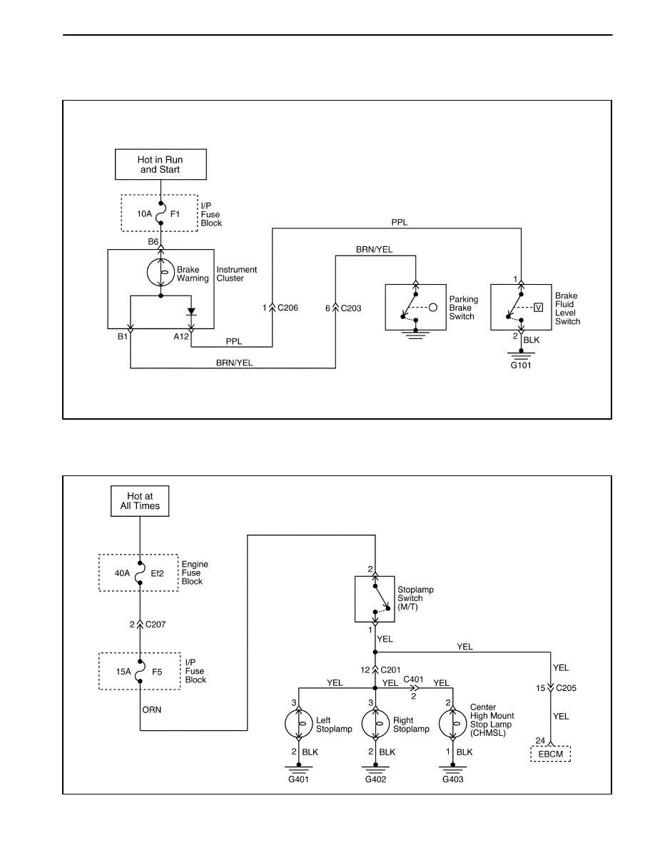
SCHEMATIC AND ROUTING DIAGRAMS
BRAKE LAMP WARNING CIRCUIT
D17A201B
STOPLAMP SWITCH CIRCUIT
D17A202B
Wyszukiwarka
Podobne podstrony:
HYDRAULIC BRAKES 4A 19
38 Zawory hydrauliczne
Właściwości hydrauliczne
hydraulika oprcowanie pytania 2013 (chyba)
AVB hydrauliczne naprążanie paska rozrządu
45 06 BW Hydraulika stosowana
Instrukcja 16 Rozpoznawanie elementow hydraul
Hydraulika02
INSTRUKCJA OBSŁUGI HYDRAULICZNEJ NADZIEWARKI DO KIEŁBAS(1), GOTOWANIE I ŻYWIENIE, GASTRONOMIA
Cwiczenie zabawowe, STUDIA, Polibuda - semestr II, Hydraulika i hydrologia, laborki z hydro
Lab. N1 (5 semestr), BUDOWNICTWO ZUT, SEMESTR V, Hydraulika i Hydrologia
linia cisnien, STUDIA, Polibuda - semestr II, Hydraulika i hydrologia, laborki z hydro, laborki
OBLICZANIE HYDRAULICZNE PRZEWODÓW, Inżynieria Środowiska, Różne
straty lokalne, STUDIA BUDOWNICTWO WBLIW, hydraulika i hydrologia
więcej podobnych podstron