
SECTION : 4A
HYDRAULIC BRAKES
CAUTION : Disconnect the negative battery cable before removing or installing any electrical unit or when a tool
or equipment could easily come in contact with exposed electrical terminals. Disconnecting this cable will help
prevent personal injury and damage to the vehicle. The ignition must also be in LOCK unless otherwise noted.
TABLE OF CONTENTS
SPECIFICATIONS
4A–1
. . . . . . . . . . . . . . . . . . . . . . . . . .
GENERAL SPECIFICATIONS
4A–1
. . . . . . . . . . . . . . .
FASTENER TIGHTENING SPECIFICATIONS
4A–2
.
COMPONENT LOCATOR
4A–3
. . . . . . . . . . . . . . . . . . . .
BRAKE SYSTEM (ABS)
4A–3
. . . . . . . . . . . . . . . . . . . .
BRAKE SYSTEM (NON–ABS)
4A–4
. . . . . . . . . . . . . .
DIAGNOSIS
4A–5
. . . . . . . . . . . . . . . . . . . . . . . . . . . . . . . .
BRAKE SYSTEM TESTING
4A–5
. . . . . . . . . . . . . . . .
BRAKE HOSE INSPECTION
4A–5
. . . . . . . . . . . . . . . .
WARNING LAMP OPERATION
4A–5
. . . . . . . . . . . . . .
BRAKE LAMP WARNING CIRCUIT DIAGNOSIS 4A–
6
MAINTENANCE AND REPAIR
4A–10
. . . . . . . . . . . . . .
ON–VEHICLE SERVICE
4A–10
. . . . . . . . . . . . . . . . . . . .
MANUAL BLEEDING THE BRAKES
4A–10
. . . . . . . .
PRESSURE BLEEDING THE BRAKES
4A–13
. . . . .
BRAKE HOSE REAR
4A–14
. . . . . . . . . . . . . . . . . . . . .
BRAKE HOSE FRONT
4A–15
. . . . . . . . . . . . . . . . . . .
STOPLAMP SWITCH
4A–17
. . . . . . . . . . . . . . . . . . . . .
BRAKE PEDAL
4A–17
. . . . . . . . . . . . . . . . . . . . . . . . . .
GENERAL DESCRIPTION AND SYSTEM
OPERATION
4A–19
. . . . . . . . . . . . . . . . . . . . . . . . . . . . .
HYDRAULIC FLUID
4A–19
. . . . . . . . . . . . . . . . . . . . . . .
SPECIFICATIONS
GENERAL SPECIFICATIONS
Application
2.0 DOHC Engine
Millimeters
Inches
Brake Drums:
Inside Diameter
Maximum Rebore Di-
ameter
Out–of–Round
200
201
0.08
7.87
7.91
0.0032
Front Brake Rotors:
Discard Thickness
Lateral Runout
(Installed)
Rotor Diameter
Rotor Thickness (New)
Thickness Variation
22.00
0.030
256
24.00
0.005
0.87
0.001
10.07
0.95
0.0005

4A – 2
I
HYDRAULIC BRAKES
DAEWOO V–121 BL4
Application
Inches
Millimeters
Rear Brake Rotors:
Discard Thickness
Lateral Runout
(Installed)
Rotor Diameter
Rotor Thickness (New)
Thickness Variation
8.4
0.03
258.00
10.40
0.005
0.33
0.004
10.16
0.41
0.0004
Master Cylinder:
Bore Diameter (Nomi-
nal)
Bore Diameter (Maxi-
mum)
23.81
23.86
0.937
0.937
Caliper:
Minimum Piston Diam-
eter (Front)
Minimum Piston Diam-
eter (Rear)
57.00
35.00
2.244
1.377
Wheel Cylinder Diameter:
Maximum
Nominal
–
–
–
–
FASTENER TIGHTENING SPECIFICATIONS
Application
N
S
m
Lb–Ft
Lb–In
Bleeder Screw
8
–
53
Brake Lines
16
12
–
Front Disc Brake Hose–to–Caliper Bolt
40
30
–
Rear Disc Brake Hose–to–Caliper Bolt
32
24
–
Shaft Nut
18
13
–
HYDRAULIC BRAKES 4A – 3
DAEWOO V–121 BL4
COMPONENT LOCATOR
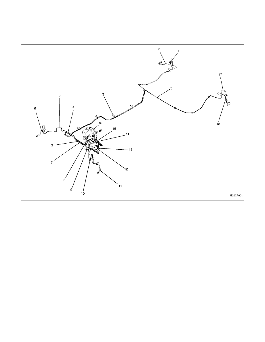
BRAKE SYSTEM (ABS)
1. RH Rear Brake Hose
2. RH 3rd Rear Brake Pipe
3. Clip
4. 2nd Rear Brake Pipe (A)
5. 2nd Front Brake Pipe
6. RH Front Brake Hose
7. 2nd Rear Brake Pipe (B)
8. ABS
Modulator
9. Bracket
10. Front Brake Pipe
11. LH Front Brake Hose
12. Connector
13. 1st Rear Brake Pipe (A)
14. 1st Front Brake Pipe
15. 1st Rear Brake Pipe (B)
16. LHD Master Cylinder/Booster Assembly
17. LH Rear Brake Hose
18. LH 3rd Rear Brake Pipe
4A – 4
I
HYDRAULIC BRAKES
DAEWOO V–121 BL4
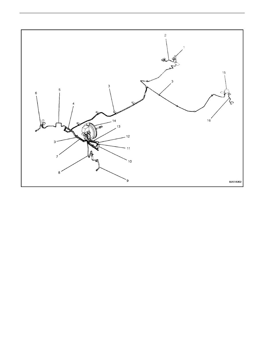
BRAKE SYSTEM (NON–ABS)
1. RH Rear Brake Hose
2. RH 3rd Rear Brake Pipe
3. Clip
4. 2nd Rear Brake Pipe
5. 2nd Front Brake Pipe
6. RH Front Brake Hose
7. 2nd Rear Brake Pipe
8. Front Brake Pipe
9. LH Front Brake Hose
10. Connector
11. 1st Rear Brake Pipe (A)
12. 1st Front Brake Pipe
13. 1st Rear Brake Pipe (B)
14. LHD Master Cylinder/Booster Assembly
15. LH Rear Brake Hose
16. LH 3rd Rear Brake Pipe

HYDRAULIC BRAKES 4A – 5
DAEWOO V–121 BL4
DIAGNOSIS
BRAKE SYSTEM TESTING
Brakes should be tested on a dry, clean, reasonably
smooth and level roadway. A true test of brake perfor-
mance cannot be made if the roadway is wet, greasy, or
covered with loose dirt whereby all tires do not grip the
road equally. Testing will also be adversely affected if the
roadway is crowned so as to throw the weight so roughly
that the wheels tend to bounce.
Test the brakes at different vehicle speeds with both light
and heavy pedal pressure; however, avoid locking the
brakes and sliding the tires. Locked brakes and sliding
tires do not indicate brake efficiency since heavily braked,
but turning, wheels will stop the vehicle in less distance
than locked brakes. More tire–to–road friction is present
with a heavily–braked, turning tire than with a sliding tire.
Because of the high deceleration capability, a firmer pedal
may be felt at higher deceleration levels.
There are three major external conditions that affect brake
performance:
S
Tires having unequal contact and grip of the road
will cause unequal braking. Tires must be equally
inflated, and the tread pattern of the right and the
left tires must be approximately equal.
S
Unequal loading of the vehicle can affect the brake
performance since the most heavily loaded wheels
require more braking power, and thus more braking
effort, than the others.
S
Misalignment of the wheels, particularly conditions
of excessive camber and caster, will cause the
brakes to pull to one side.
To check for brake fluid leaks, hold constant foot pressure
on the pedal with the engine running at idle and the shift
lever in NEUTRAL. If the pedal gradually falls away with
the constant pressure, the hydraulic system may be leak-
ing. Perform a visual check to confirm any suspected
leaks.
Check the master cylinder fluid level. While a slight drop
in the reservoir level results from normal lining wear, an ab-
normally low level indicates a leak in the system. The hy-
draulic system may be leaking either internally or external-
ly. Refer to the procedure below to check the master
cylinder. Also, the system may appear to pass this test
while still having a slight leak. If the fluid level is normal,
check the vacuum booster pushrod length. If an incorrect
pushrod length is found, adjust or replace the rod.
Check themaster cylinder using the following procedure:
S
Check for a cracked master cylinder casting or
brake fluid leaking around the master cylinder.
Leaks are indicated only if there is at least one drop
of fluid. A damp condition is not abnormal.
S
Check for a binding pedal linkage and for an incor-
rect pushrod length. If both of these parts are in
satisfactory condition, disassemble the master cyl-
inder and check for an elongated or swollen primary
cylinder or piston seals. If swollen seals are found,
substandard or contaminated brake fluid should be
suspected. If contaminated brake fluid is found, all
the components should be disassembled and
cleaned, and all the rubber components should be
replaced. All of the pipes must also be flushed.
Improper brake fluid, or mineral oil or water in the fluid,
may cause the brake fluid to boil or cause deterioration of
the rubber components. If the primary piston cups in the
master cylinder are swollen, then the rubber parts have
deteriorated. This deterioration may also be evidenced by
swollen wheel cylinder piston seals on the drum brake
wheels.
If deterioration of rubber is evident, disassemble all the hy-
draulic parts and wash the parts with alcohol. Dry these
parts with compressed air before reassembly to keep alco-
hol out of the system. Replace all the rubber parts in the
system, including the hoses. Also, when working on the
brake mechanisms, check for fluid on the linings. If exces-
sive fluid is found, replace the linings.
If the master cylinder piston seals are in satisfactory condi-
tion, check for leaks or excessive heat conditions. If these
conditions are not found, drain the fluid, flush the master
cylinder with brake fluid, refill the master cylinder, and
bleed the system. Refer to”Manual Bleeding the Brakes”
or”Pressure Bleeding the Brakes” in this section.
BRAKE HOSE INSPECTION
The hydraulic brake hoses should be inspected at least
twice a year. The brake hose assembly should be checked
for road hazard damage, cracks, chafing of the outer cov-
er, and for leaks or blisters. Inspect the hoses for proper
routing and mounting. A brake hose that rubs on a suspen-
sion component will wear and eventually fail. A light and
a mirror may be needed for an adequate inspection. If any
of the above conditions are observed on the brake hose,
adjust or replace the hose as necessary.
WARNING LAMP OPERATION
This brake system uses a BRAKE warning lamp located
in the instrument panel cluster. When the ignition switch
is in the START position, the BRAKE warning lamp should
glow and go OFF when the ignition switch returns to the
RUN position.
The following conditions will activate the BRAKE lamp:
S
Parking brake applied. The light should be ON
whenever the parking brake is applied and the igni-
tion switch is ON.
S
Low fluid level. A low fluid level in the master cylin-
der will turn the BRAKE lamp ON.
S
As a test of the lamp circuit, vehicles with antilock
brakes will momentarily illuminate the lamp for
about 4 seconds when the ignition
4A – 6
I
HYDRAULIC BRAKES
DAEWOO V–121 BL4
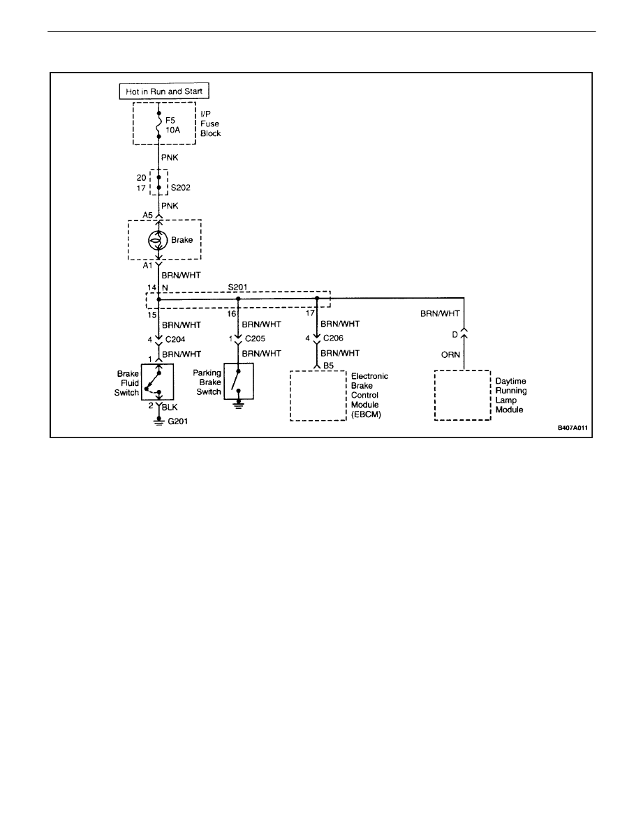
BRAKE LAMP WARNING CIRCUIT DIAGNOSIS
Test Description
The number(s) below refer to step(s) on the diagnostic
table.
1.
When the ignition is turned ON, the brake warning
lamp should initially illuminate and then dim for ABS
equipped vehicles. This is done as a bulb check.
On vehicles that are not equipped with ABS, the
brake warning lamp should only illuminate when
either the brake fluid reservoir is low or the parking
brake is applied.
7.
The brake fluid level switch is a normally open
switch. If the brake warning lamp is off after discon-
necting the switch, the brake fluid level switch is
stuck closed.
9.
If the brake warning lamp is still on after discon-
necting the parking brake switch, there is a short to
ground in the wire to the parking brake switch.
12. If the other checks have been properly performed
and the brake warning lamp is off after disconnect-
ing the electronic brake control module (EBCM) J1
connector, the EBCM is faulty.
19. If the brake warning lamp does not operate while
performing any of the functions, the fault should be
in the ignition feed to the circuit.
24. This step determines if the problem is in the ignition
feed to the circuit or in the instrument cluster.
30. The brake warning lamp should illuminate when
jumpering the parking brake connector to ground.
32. If the brake warning lamp is on after jumpering the
brake fluid level switch terminals, the switch is
faulty.

HYDRAULIC BRAKES 4A – 7
DAEWOO V–121 BL4
Brake Lamp Warning Circuit Diagnosis
Step
Action
Value(s)
Yes
No
1
Turn the ignition ON.
Is the brake warning lamp always on?
Go toStep 2
Go toStep 18
2
Check the ABS warning lamp.
Is the ABS warning lamp also on?
Go toStep 3
Go toStep 4
3
Use a scan tool to check for diagnostic trouble codes
(DTCs) and follow the procedures for any DTCs
found.
Is the lamp still on?
Go toStep 4
System OK
4
Release the parking brake fully.
Is the lamp off?
System OK
Go toStep 5
5
Check the brake fluid level.
Is the fluid level OK?
Go toStep 7
Go toStep 6
6
1. Fill the brake fluid reservoir with clean DOT 3
equivalent hydraulic fluid.
2. Replace the cap on the fluid reservoir.
Is the lamp on?
Go toStep 7
System OK
7
Disconnect the harness connector from the brake
fluid level switch.
Is the lamp on?
Go toStep 9
Go toStep 8
8
Replace the brake fluid level switch.
Is the repair complete?
System OK
9
1. Connect the brake fluid level switch.
2. Disconnect the parking brake switch.
Is the lamp on?
Go toStep 11
Go toStep 10
10
Replace the parking brake switch.
Is the repair complete?
System OK
11
Connect the parking brake switch.
Is the vehicle equipped with ABS?
Go toStep 12
Go toStep 14
12
1. Turn the ignition OFF.
2. Disconnect the electronic brake control module
(EBCM) connector.
3. Turn the ignition ON.
Is the lamp on?
Go toStep 14
Go toStep 13
13
Replace the electronic brake control module
(EBCM).
Is the repair complete?
System OK
14
1. Turn the ignition OFF.
2. Connect the EBCM connector.
3. Check for a short to ground in the wiring be-
tween the instrument cluster terminal A2 and
the brake fluid level switch.
Is the problem found?
Go toStep 17
Go toStep 15
15
Check for a short to ground in the wiring between the
instrument cluster terminal A2 and the parking brake
switch.
Is the problem found?
Go toStep 17
Go toStep 16

4A – 8
I
HYDRAULIC BRAKES
DAEWOO V–121 BL4
Step
No
Yes
Value(s)
Action
16
Check for a short to ground in the wiring between the
instrument cluster terminal A2 and the EBCM con-
nector terminal 21.
Is the problem found?
Go toStep 17
Go toStep 18
17
Repair the wiring as needed.
Is the repair complete?
System OK
18
Check the brake lamp after doing each of the follow-
ing functions:
S
Apply the parking brake.
S
Remove the cap from the brake fluid reservoir.
S
On vehicles equipped with ABS, command the
lamp on using a scan tool.
Does the brake warning lamp operate for all of these
conditions?
System OK
Go toStep 19
19
When the operations listed in step 18 were per-
formed, the brake warning lamp did not function.
Did the brake warning lamp fail to light for all of the
operations listed in step 18?
Go toStep 20
Go toStep 27
20
1. Turn the ignition OFF.
2. Inspect the kick panel fuse F5.
Is the fuse OK?
Go toStep 22
Go toStep 21
21
Replace the fuse.
Is the repair complete?
System OK
22
Inspect the brake warning lamp bulb.
Is the bulb OK?
Go toStep 24
Go toStep 23
23
Replace the bulb.
Is the repair complete?
System OK
24
1. Disconnect the instrument cluster connector.
2. Turn the ignition ON.
3. Measure the voltage at the instrument cluster
connector terminal A2.
Does the voltagemeasurewithin the value specified?
11–14 v
Go toStep 25
Go toStep 26
25
1. Turn the ignition OFF.
2. Repair the open in the instrument cluster.
Is the repair complete?
System OK
26
1. Turn the ignition OFF.
2. Repair the open in the wiring between the in-
strument cluster connector terminal A2 and the
ignition switch.
Is the repair complete?
System OK
27
Apply the parking brake again.
Does the parking brake warning lamp operate with
the parking brake applied?
Go toStep 28
Go toStep 30
28
Remove the brake fluid reservoir cap.
Does the parking brake warning lamp operate with
the cap from the brake fluid reservoir removed?
Go toStep 29
Go toStep 32
29
Check for an open between the instrument cluster
connector terminal B13 and the EBCM connector
terminal 21.
Is the problem found?
Go toStep 17
Go toStep 13

HYDRAULIC BRAKES 4A – 9
DAEWOO V–121 BL4
Step
No
Yes
Value(s)
Action
30
1. Turn the ignition ON.
2. Disconnect the parking brake switch.
3. Jumper the parking brake switch connector
terminal to ground.
Is the lamp on?
Go toStep 10
Go toStep 31
31
1. Turn the ignition OFF.
2. Repair the open in the wire between the instru-
ment cluster connector terminal B13 and the
parking brake switch connector terminal.
Is the repair complete?
System OK
32
1. Disconnect the brake fluid level switch.
2. Turn the ignition ON.
3. Jumper the brake fluid level switch connector
terminals.
Is the lamp on?
Go toStep 8
Go toStep 33
33
1. Turn the ignition OFF.
2. Connect a test light between battery positive
and the BRN/WHT wire terminal of the brake
fluid level switch.
Is the test light on?
Go toStep 34
Go toStep 35
34
Repair the open in the wiring between ground and
the brake fluid level switch.
Is the repair complete?
System OK
35
Repair the open in the wiring between the instrument
cluster connector terminal B13 and the brake fluid
level switch.
Is the repair complete?
System OK
4A – 10
I
HYDRAULIC BRAKES
DAEWOO V–121 BL4
MAINTENANCE AND REPAIR
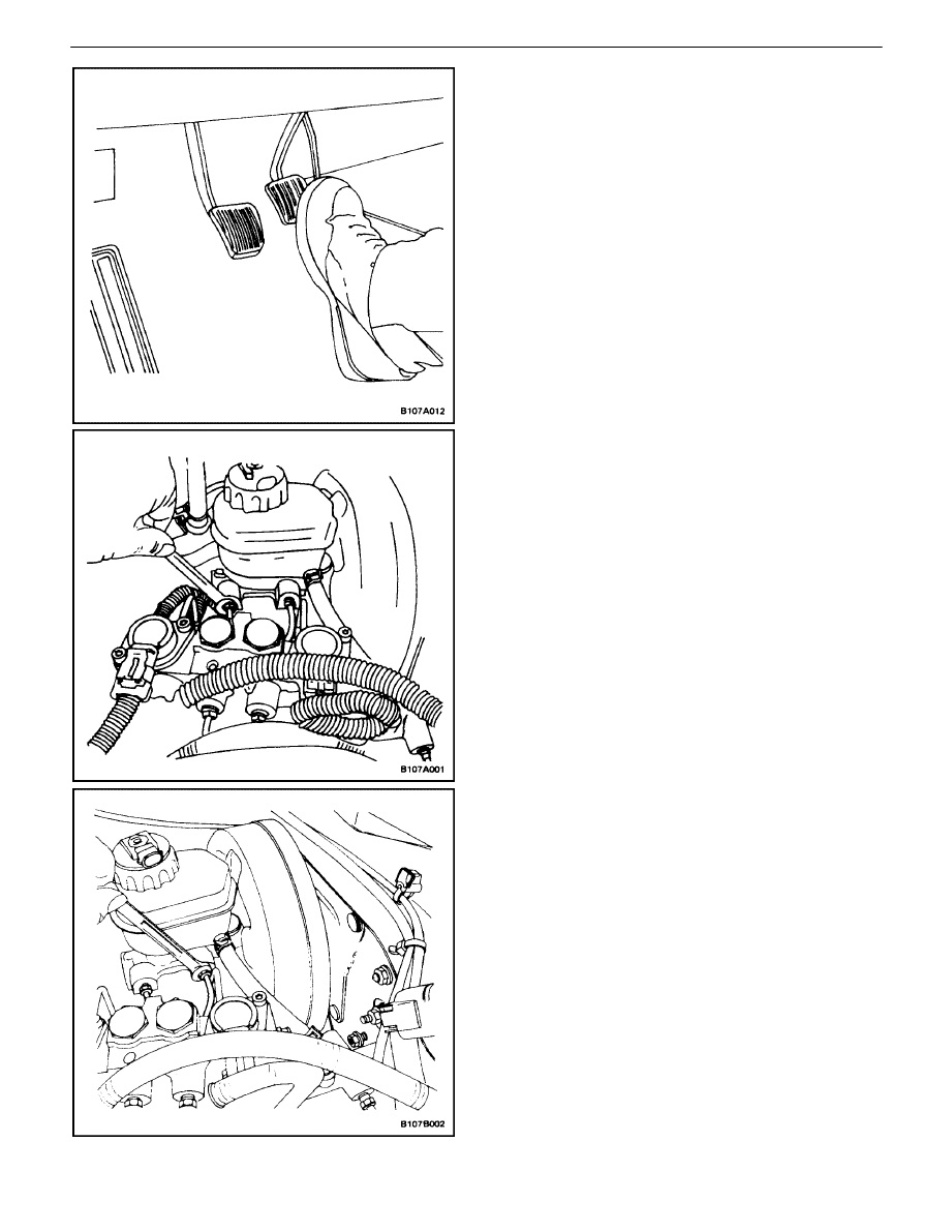
ON–VEHICLE SERVICE
MANUAL BLEEDING THE BRAKES
1. Remove the booster reserve by applying the brakes
several times with the engine OFF until all the re-
serve is depleted.
Important : If the master cylinder is known or suspected
to have air in the bore, then it must be bled before any
wheel cylinder or caliper is bled.
2. Fill the master cylinder reservoir with brake fluid.
Keep the master cylinder at least one–half full of
fluid during the bleeding operation.
3. Disconnect the front brake line(s) at the master cyl-
inder.
4. Allow the brake fluid to fill the master cylinder until it
begins to flow from the front pipe connector port.
5. Connect the front brake line(s) to the master cylin-
der.
Tighten
Tighten the brake lines to 16 N
S
m (12 lb–ft).
HYDRAULIC BRAKES 4A – 11
DAEWOO V–121 BL4
6. Slowly push and hold the brake pedal one time.
7. Loosen the front brake line at the master cylinder to
purge air from the cylinder.
8. Tighten the brake line (as in step 5), and then re-
lease the brake pedal slowly. Wait 15 seconds be-
fore proceeding to the next step.
9. Repeat the sequence, including the 15–second
wait, until all the air is removed from the master
cylinder bore.
Notice : Care must be taken to prevent brake fluid from
contacting any painted surface to prevent damage to the
paint finish.
10. After all the air has been removed at the forward
connection(s), bleed the master cylinder at the rear
(cowl) connection(s) in the same manner as with
the front connections.

4A – 12
I
HYDRAULIC BRAKES
DAEWOO V–121 BL4
Important : For vehicles equipped with a non–antilock
braking system, the bleeding sequence is as follows: right
rear, left rear, left front and right front. For ABS vehicles,
refer toSection 4F, Antilock Brake System for the correct
sequence and bleeding procedure.
11. Attach a transparent tube over the valve. Allow the
tube to hang submerged in brake fluid in a transpar-
ent container.
12. Slowly push and hold the brake pedal one time.
13. Remove the bleeder valve dust cover and loosen
the bleeder screw to purge the air from the cylinder.
14. Slowly release the brake pedal. Wait 15 seconds
before proceeding with the next step.
Important : Rapid pumping of the brake pedal pushes the
master cylinder secondary piston down the bore in a man-
ner that makes it difficult to bleed the system.
15. Repeat the sequence, including the 15–second
wait, until all the air is removed. It may be neces-
sary to repeat the sequence 10 or more times to
remove all the air.
16. Tighten the bleeder screw.
Tighten
Tighten the bleeder screw to 8 N
S
m (71 lb–in).
17. Proceed to bleed the front brakes following the ap-
propriate sequence, beginning with step 12.
18. Check the brake pedal for sponginess. Repeat the
entire bleeding procedure to correct this condition.
HYDRAULIC BRAKES 4A – 13
DAEWOO V–121 BL4
PRESSURE BLEEDING THE BRAKES
Notice : Pressure bleeding equipment must be of the
diaphragmtype. It must have a rubber diaphragm between
the air supply and the brake fluid to preventir, moisture, oil,
and other contaminants from entering the hydraulic sys-
tem. Contamination could lead to deterioration of the rak-
ing components and loss of braking action.
1. Disconnect the master cylinder electrical connector.
2. Remove the master cylinder reservoir cap.
3. Connect the bleeder with the adapter to the master
cylinder reservoir.
4. For vehicles with the antilock braking system
(ABS), locate and remove the hydraulic modulator
bleeder valves. Refer toSection 4F, Antilock Brake
System
5. Charge the bleeder ball to 140 to 172 kPa (20 to 25
psi).
6. Connect the line to the adapter. Open the line
valve.
7. Raise and suitably support the vehicle.
Important : The bleeding sequence is as follows: right
rear, left front, left rear and right front.
8. Attach the bleeder hose to the bleeder valve. Sub-
merge the opposite end of the hose in a clean con-
tainer partially filled with brake fluid.
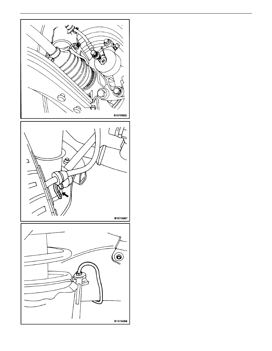
9. A107A006 Open the bleeder valve one–half to
three–fourths turn and allow the fluid to flow until no
air is seen in the fluid.
Notice : After the bleeding operation, the brake reservoir
may be pressurized. While disconnecting the bleeder
hose or the unthreaded adapter cap, cover the cap and the
connection with a shop towel to protect painted surfaces
from contact with the brake fluid.
10. Inspect the brake pedal for sponginess. Repeat the
entire bleeding procedure to correct this condition.
11. Tighten the bleeder valve and replace the dust cov-
ers.
Tighten
Tighten the bleeder valve to 8 N
S
m (71 lb–in).
4A – 14
I
HYDRAULIC BRAKES
DAEWOO V–121 BL4
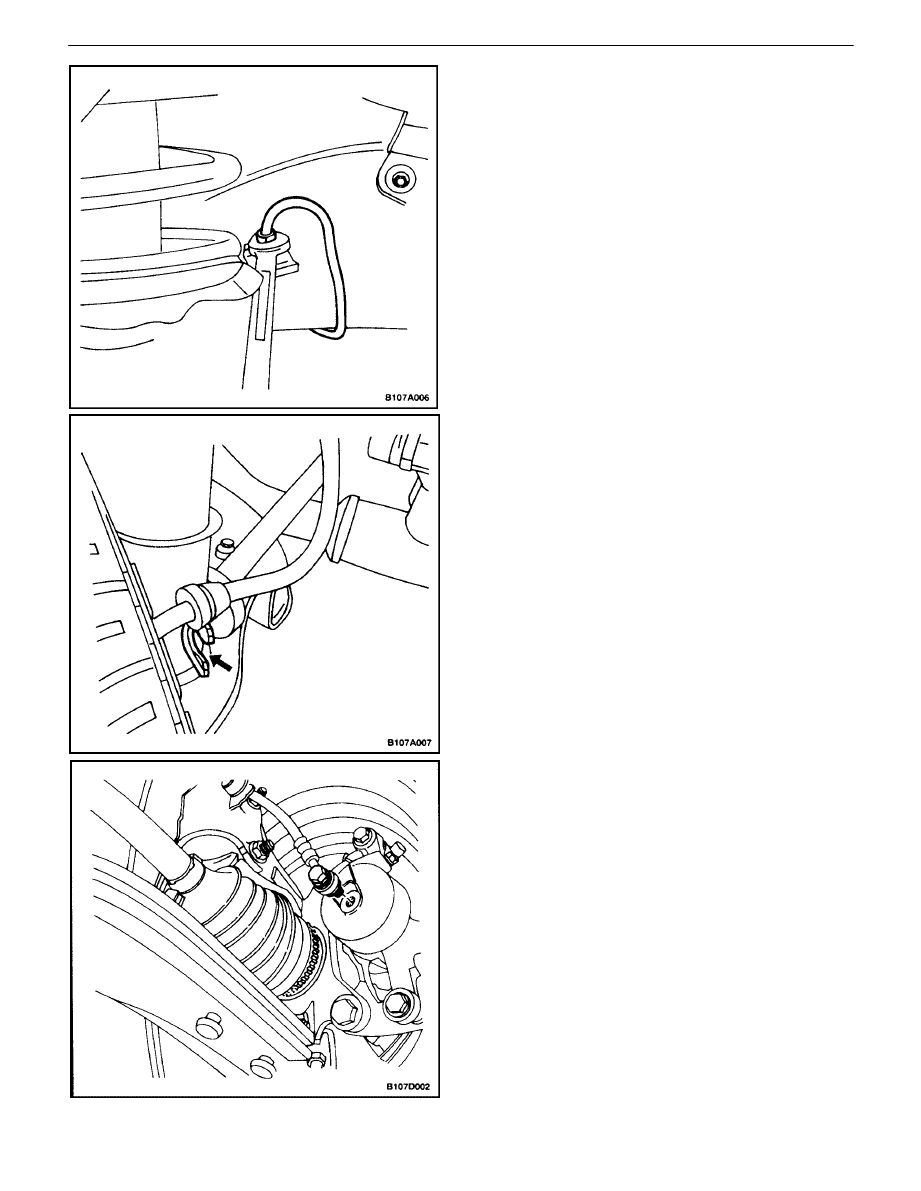
BRAKE HOSE REAR
Removal Procedure
1. Raise and suitably support the vehicle.
2. Disconnect the brake line from the disc brake hose
at the wheel housing bracket on each side of the
vehicle.
3. Remove the brake hose retainer.
4. Remove the rear disc brake hose retainer and the
brake hose from the bracket on the steering
knuckle shaft.
5. Remove the rear disc brake hose from the caliper.
Installation Procedure
1. Install the rear disc brake hose to the caliper.
Tighten
Tighten the rear disc brake hose–to–caliper bolt to 32
N
S
m (24 lb–ft).
2. Install the rear disc brake hose and retainer on the
bracket on the steering knuckle shaft
3. Install the rear disc brake line to the brake hose on
the wheel housing bracket.
Tighten
Tighten the brake line to 16 N
S
m (12 lb–ft).
4. Lower the vehicle.
5. Bleed the brake system. Refer to”Manual Bleeding
the Brakes”in this section, or Section 4F, Antilock
Brakes, if applicable.
6. Check the brake system for leaks.
HYDRAULIC BRAKES 4A – 15
DAEWOO V–121 BL4
BRAKE HOSE FRONT
Removal Procedure
1. Raise and suitably support the vehicle.
2. Disconnect the brake line from the brake hose sup-
port bracket on the wheel housing on each side of
the vehicle.
3. Remove the retainer.
4. Disconnect the brake hose from the ”C” bracket on
the steering knuckle shaft.
5. Remove the bolt from the brake caliper.
6. Remove the seal rings and the disc brake hose.
4A – 16
I
HYDRAULIC BRAKES
DAEWOO V–121 BL4
Installation Procedure
1. Install the new disc brake hose to the caliper with
new seal rings and the bolt.
Tighten
Tighten the front disc brake hose–to–caliper bolt to 40
N
S
m (30 lb–ft).
2. Slide the brake hose on the steering knuckle shaft
”C” bracket.
3. Connect the brake line to the brake hose on the
wheel housing bracket on each side of the vehicle.
Tighten
Tighten the brake line to 16 N
S
m (12 lb–ft).
4. Lower the vehicle.
5. Bleed the brake system. Refer to”Manual Bleeding
the Brakes” in this section.
6. Check the brake system for leaks.
HYDRAULIC BRAKES 4A – 17
DAEWOO V–121 BL4
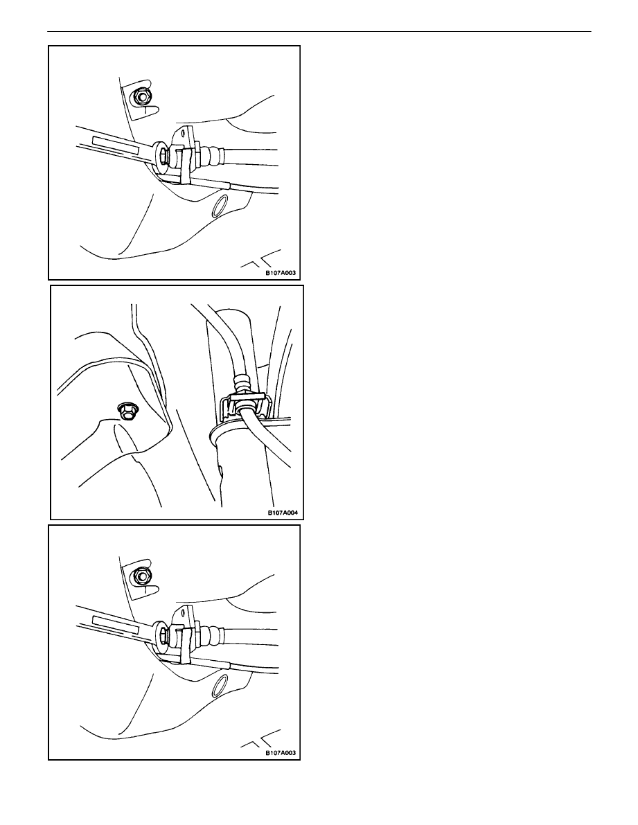
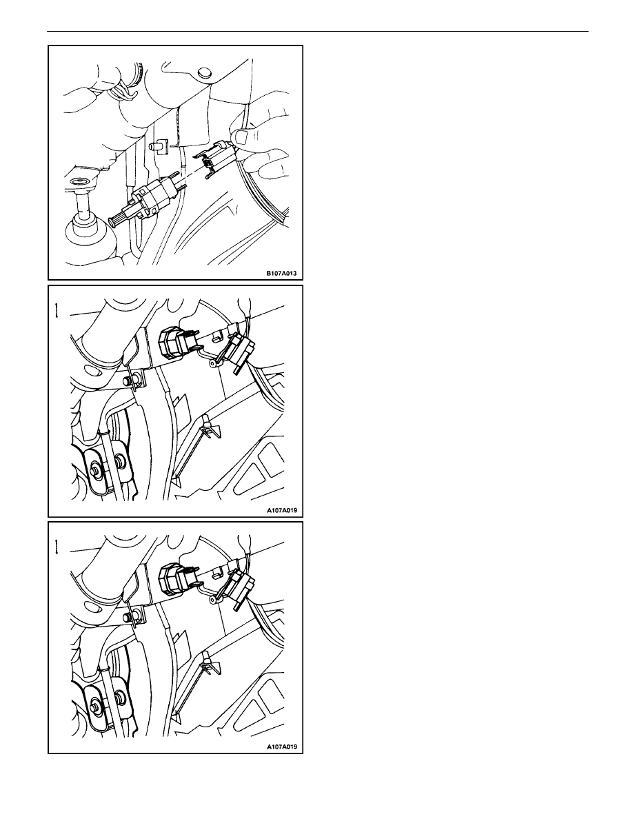
STOPLAMP SWITCH
Removal Procedure
1. Disconnect the negative battery cable.
2. Disconnect the connector from the stoplamp switch.
3. Rotate the switch and remove it from the brake
pedal bracket.
Installation Procedure
1. Insert the stoplamp switch into the brake pedal
bracket and rotate the switch to lock it.
2. Connect the electrical connector to the stoplamp
switch.
3. Press the brake pedal and pull the switch plunger to
its maximum setting to adjust the switch.
4. Release the plunger and pull up on the pedal.
5. Connect the negative battery cable.
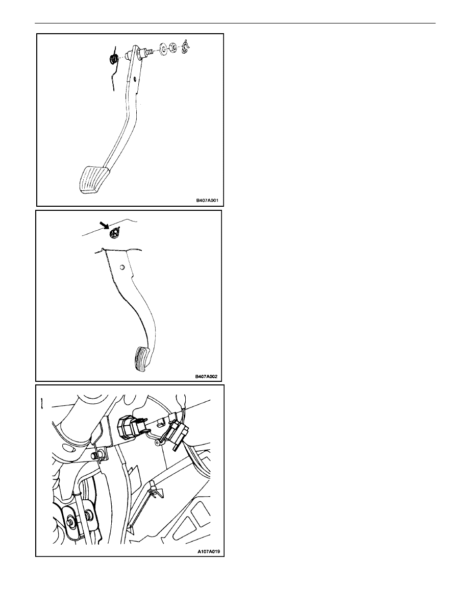
BRAKE PEDAL
Removal Procedure
1. Remove the stoplamp switch.
4A – 18
I
HYDRAULIC BRAKES
DAEWOO V–121 BL4
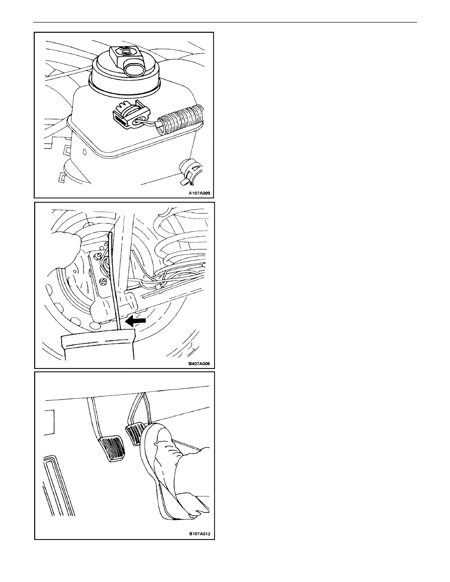
2. Notice how the brake pedal return spring is installed
so that it can be reinstalled the same way. Move
the end of the brake return spring away from the
clevis retainer on the brake pedal.
3. Remove the clip, the retainer, and the clevis pin
from the brake pedal.
4. Remove the retaining clip from the brake pedal
shaft, and remove the nut and the washer from the
shaft.
5. Remove the pedal shaft and the brake pedal.
Installation Procedure
1. Coat the pedal shaft with grease.
2. Place the brake pedal and the return spring in the
brake pedal bracket, and install the shaft, the wash-
er, and the nut.
Tighten
Tighten the shaft nut to 18 N
S
m (13 lb–ft).
3. Install the retaining clip into the hole in the pedal
shaft.
4. Align the clevis with the holes in the brake pedal,
and install the clevis pin, the clevis retainer, and the
clip.
5. Install the stoplamp switch.

HYDRAULIC BRAKES 4A – 19
DAEWOO V–121 BL4
GENERAL DESCRIPTION
AND SYSTEM OPERATION
HYDRAULIC FLUID
Brake fluid should meet the DOT–3 specification. Use
DOT–4 fluid for heavy duty applications such as trailer
towing or mountain driving. Use only clean fluid from a
sealed container. Fluid exposed to air will absorb moisture
from the air. Water in the brake fluid will cause the fluid to
boil, and the rubber components to deteriorate.
Thoroughly cleanthemaster cylinder reservoir capbefore
removing it. Do not let any dirt or foreignmaterial fall into
thefluidreservoir.
There is a fluid level switch in the master cylinder reservoir.
When the fluid level is low, the BRAKE lamp in the instru-
ment cluster will turn on. The correct brake fluid level is
marked on the driver’s side of the master cylinder reser-
voir. If the fluid level is below the MIN indicator mark, check
the hydraulic brake system for leaks and then refill the res-
ervoir to the MAX indicator mark.
Wyszukiwarka
Podobne podstrony:
M34a Hydraulic Brakes
M34a Hydraulic Brakes
19 02 W Hydraulika i hydrologia
19-02-W-Hydraulika i hydrologia
kpp 19 4a
Instrukcja 19 Hydrauliczne regulatory przeply
Instrukcja 19 Hydrauliczne regulatory przepływu
kpp 19 4a
wyklad 4a
19 Mikroinżynieria przestrzenna procesy technologiczne,
Prezentacja1 19
4a
38 Zawory hydrauliczne
19 183 Samobójstwo Grupa EE1 Pedagogikaid 18250 ppt
19 Teorie porównanie
Sys Inf 03 Manning w 19
więcej podobnych podstron