77 11 194 217
JULY 1997
Edition anglaise
General
SPECIFICATIONS
LIFTING
TOWING
LUBRICANTS CONSUMABLES
DRAINING FILLING
FC0A - FC0C - FC0D - FC0E - KC0A - KC0C - KC0D - KC0E
VALUES AND SETTINGS
Renault 1997
"The repair methods given by the manufacturer in this document are based on the
technical specifications current when it was prepared.
The methods may be modified as a result of changes introduced by the
manufacturer in the production of the various component units and accessories
from which his vehicles are constructed."
All copyrights reserved by Renault.
Copying or translating, in part or in full, of this document or use of the service part
reference numbering system is forbidden without the prior written authority of
Renault.
C
SECTION VIEW
PRO00.1

TOWING
All types
Contents
SPECIFICATIONS
Engine - Clutch - Gearbox
Vehicle identification
01-1
01-2
LIFTING
Trolley jack - Axle stands
Underbody lifts
Page
01
02
03
General
vehicle
02-1
02-2
03-1
LUBRICANTS CONSUMABLES
Packaging
04-1
DRAINING FILLING
Engine
Gearbox
Power assisted steering
04
05
05-1
05-3
05-4
VALUES AND SETTINGS
Dimensions
Capacity - Grades
Belt tension
Accessories belt tension
Timing belt tension
Tightening the cylinder head
Tyres and wheels
Brakes
Brake limiter
Underbody heights
Values for checking the front axle
geometry
Values for checking the rear axle
geometry
07
07-1
07-2
07-5
07-7
07-11
07-12
07-14
07-15
07-16
07-17
07-20
07-21
Page

The
KANGOO
Workshop Repair Manual has been prepared by specialists in repair methods
and diagnostics.
The document covers the methods and the diagnostic operations needed in order to obtain
high quality repairs for this vehicle.
However, if a removal - refitting operation involves no particular features, difficulties or
special tools, the method is not described in this manual, being considered very simple for
a vehicle repair specialist.
The labour times are the result of time and motion studies carried out in our workshops,
even though certain methods have not been described in the Workshop Repair Manual.
UNITS OF MEASUREMENT
• All dimensions are expressed in millimetres (
m m
) unless otherwise indicated.
• Tightening torques are expressed in decaNewton.metres (
daN.m
).
• Pressure are given in
bars
(reminder:
1 bar = 100 000 Pa
).
• Electrical resistance values are in Ohms (
Ω
).
• Voltages are expressed in Volts (
V
).
TOLERANCES
Tightening torques given without a tolerance must be accurate to within:
• In
degrees
:
±
3
°
.
• In
daN.m
:
±
10 %
.

SPECIFICATIONS
Engine- Clutch - Gearbox
01
Vehicle type
Engine
Type
Capacity
(cm
3
)
Clutch type
Manual gearbox type
FC0A
KC0A
D7F
1149
180 CP 3300
JB1
FC0C
KC0C
E7J
1390
180 CP 3300
JB3
FC0D
KC0D
FC0E
KC0E
F8Q
1870
200 CPOV 3250
JB1
VEHICLE IDENTIFICATION
Example : FC0A
F
: Body type
C
: Project code
0A : Engine suffix
01-1
SPECIFICATIONS
Vehicle identification
01
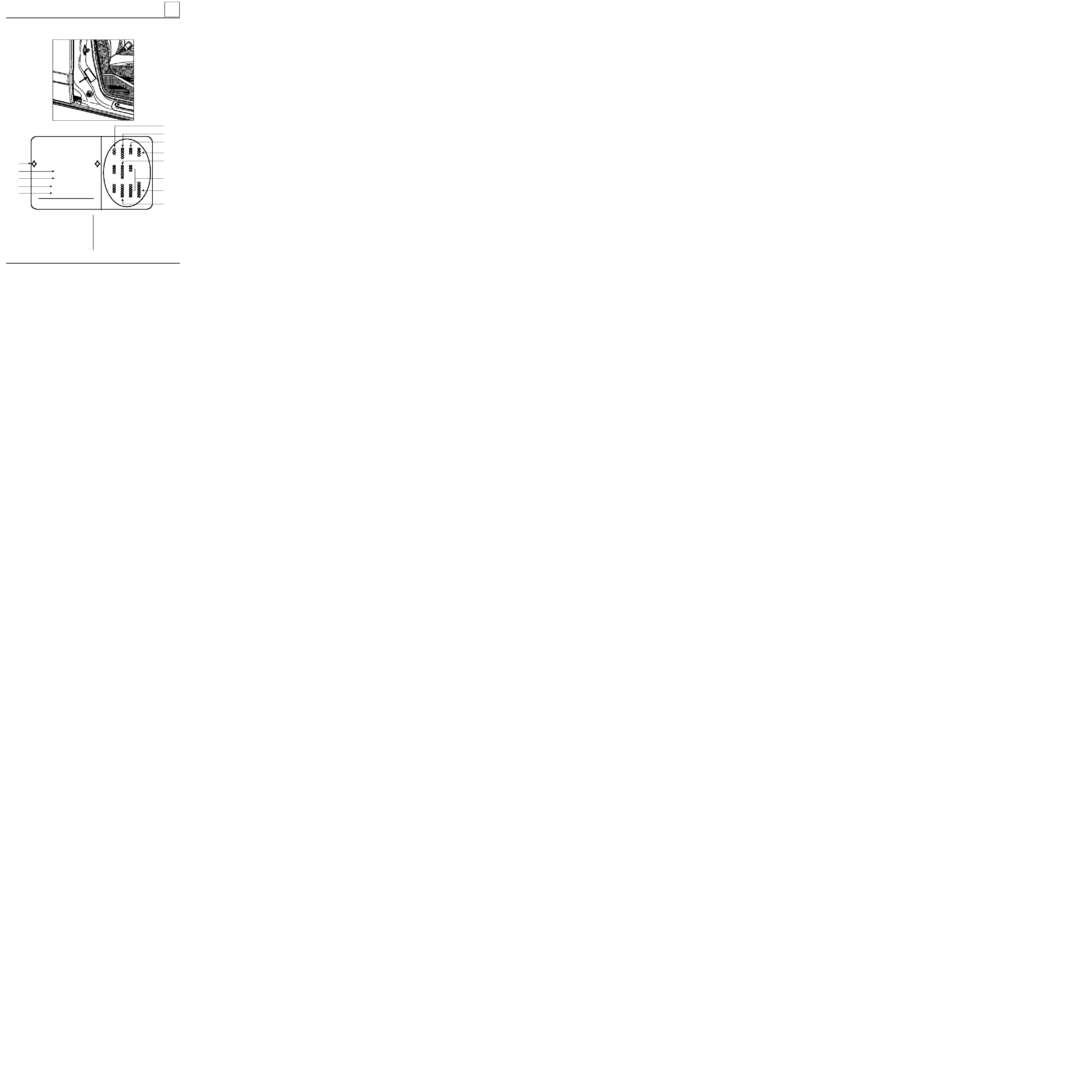
LOCATION OF VEHICLE IDENTIFICATION PLATE
e0-00/00-0000-000-000-00
VF000000000000000
0000 kg
0000 kg
1
-
0000 kg
2
-
0000 kg
000000000000000
RENAULT S.A.
1
2
3
4
5
8
7
6
9
10
13
12
11
1 Type mines of the vehicle and chassis number
2 PTMA [total all up weight of the vehicle]
3 PTR [maximum permitted total train weight -
vehicle loaded with trailer]
4 Maximum permitted weight on the front axle
(P.T.M.A. front axle)
5 Maximum permitted weight on the rear axle
(P.T.M.A. rear axle)
6
Technical specifications of the vehicle
7
Paint reference
8
Equipment level
9
Vehicle type
10 Trim code
11 Additional factory optional equipment
12 Fabrication number
13 Interior matching trim code
13187R
01-2
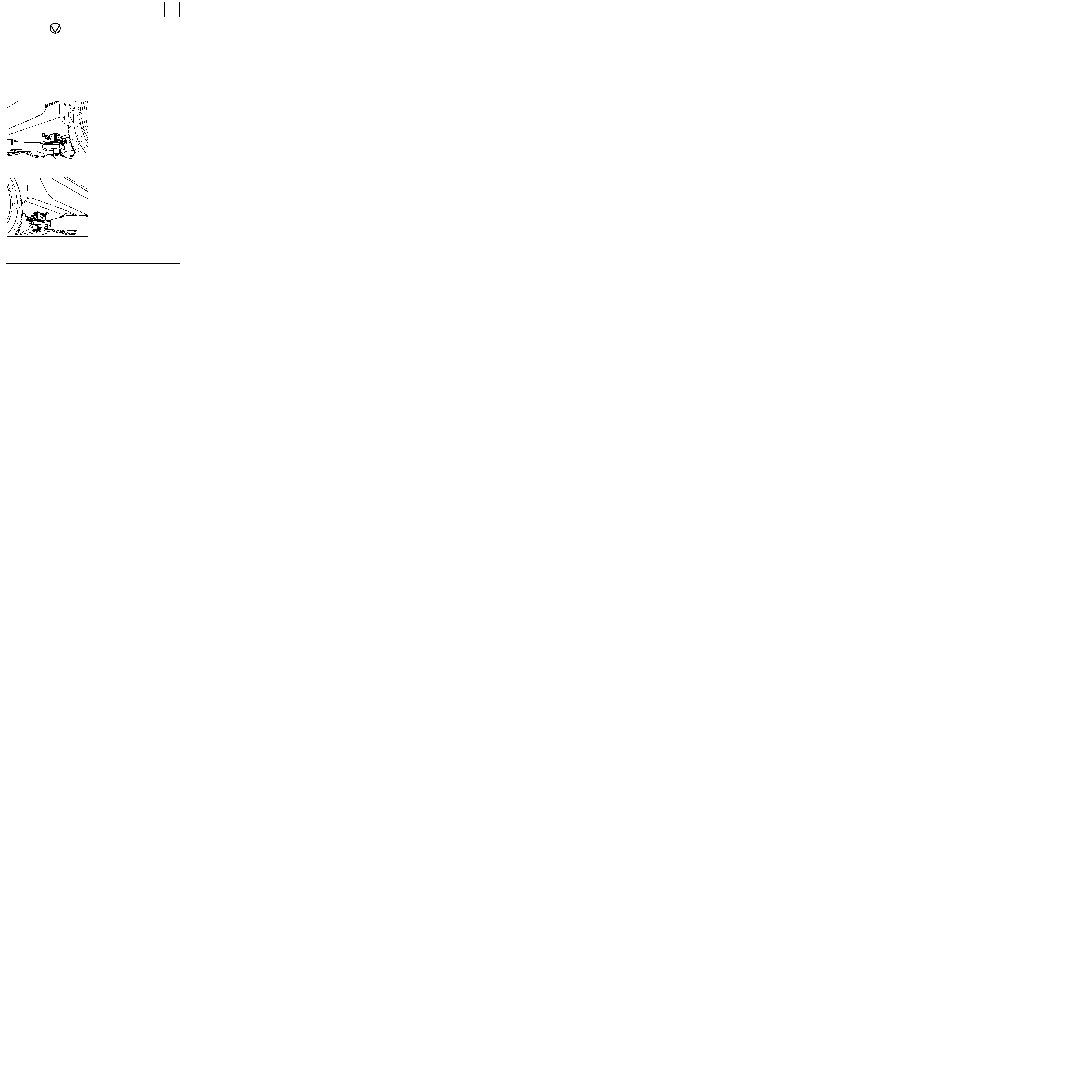
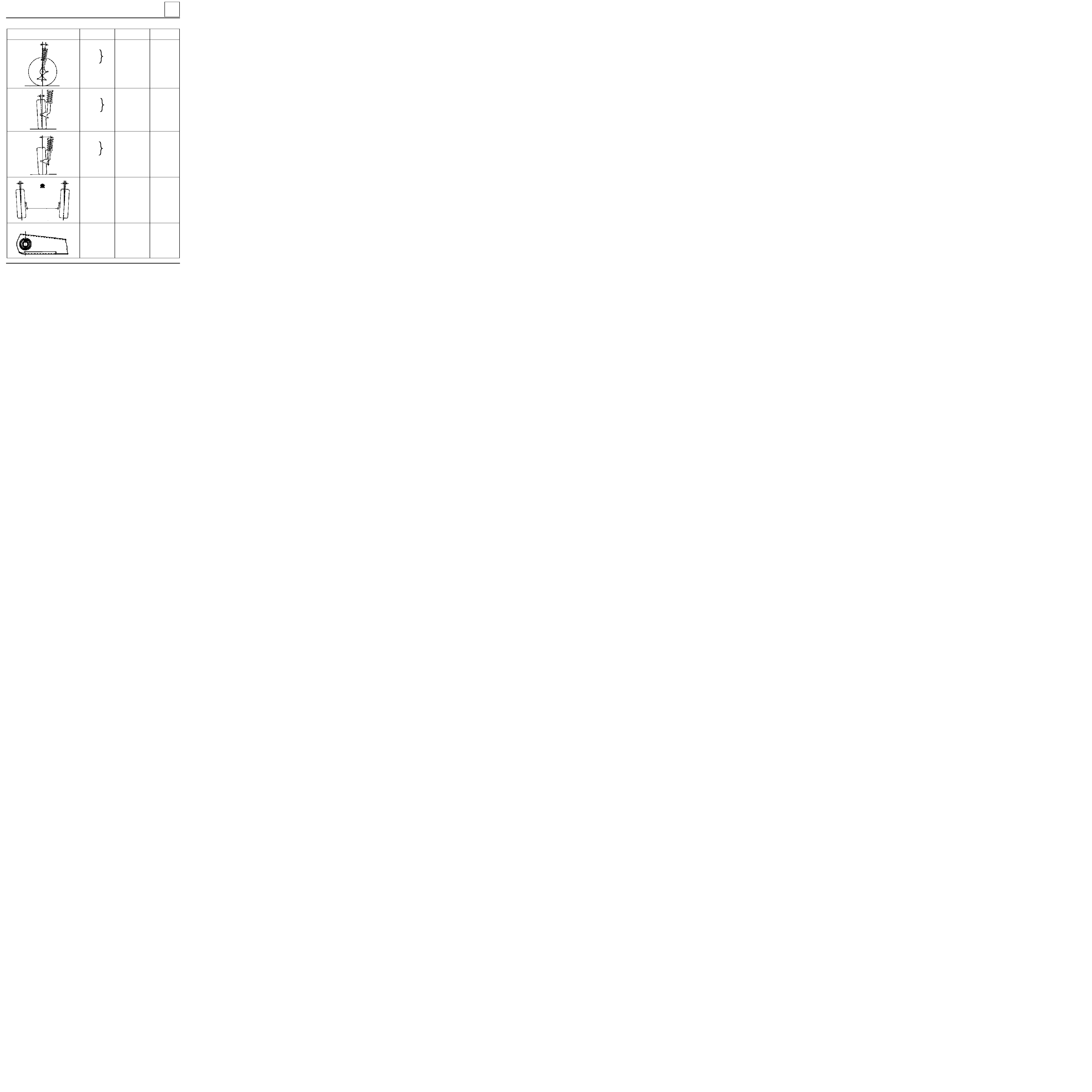
LIFTING
Trolley jack - Axle stands
AXLE STANDS
When putting the vehicle on axle stands, they
must be positioned:
_ either under the reinforcements provided for
lifting the vehicle with the tool kit jack,
- or under the studs located behind the
reinforcements.
Positioning of axle stands at the rear is carried out
by lifting the vehicle at the sides.
02
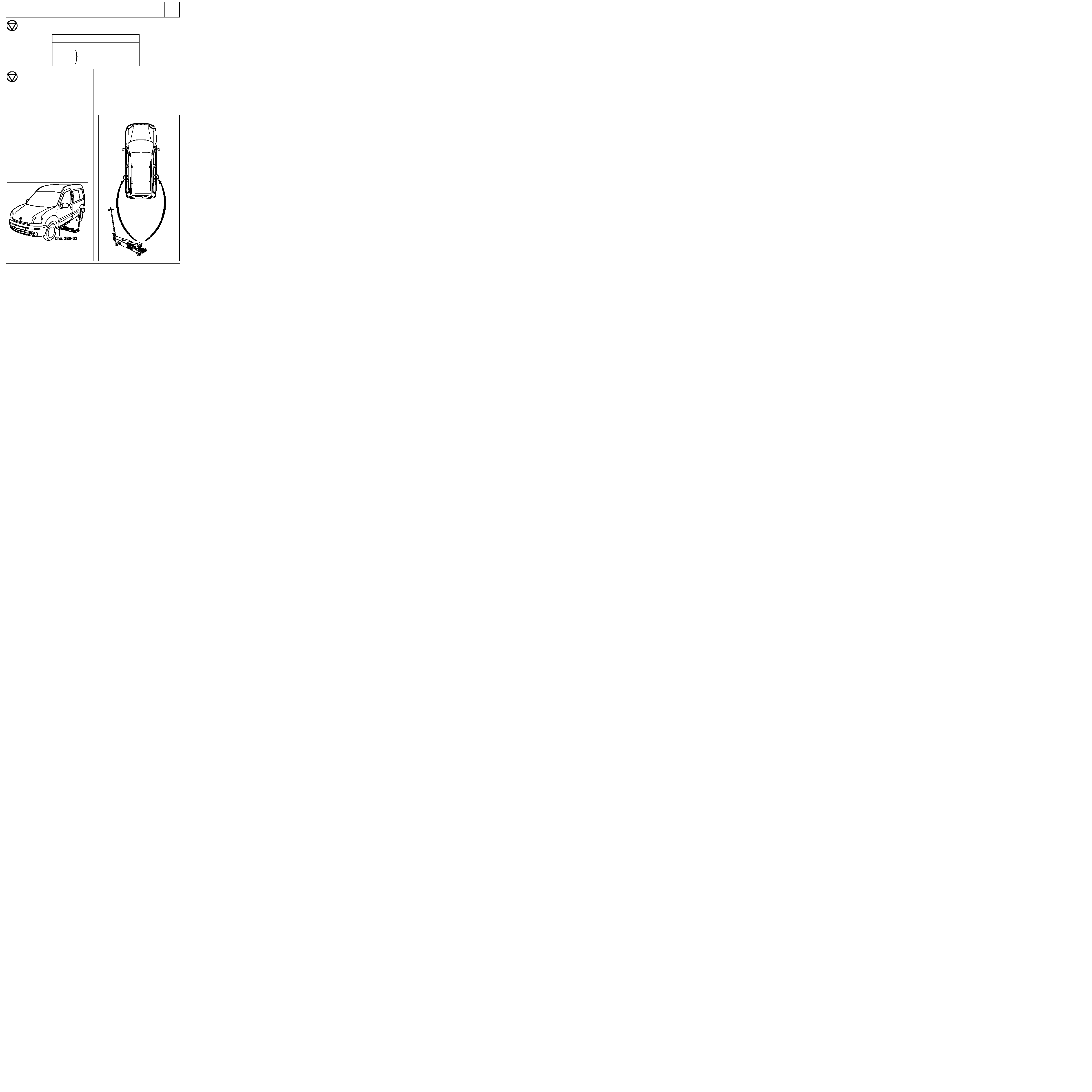
Safety symbol (special precautions to be taken when carrying out operations).
SPECIAL TOOLING REQUIRED
Cha. 280 -02
Adaptable cross piece for trolley jack
Cha. 408 -01
or
Adaptable socket for trolley jack
Cha. 408 -02
If a trolley jack is used, appropriate axle
stands must always be used.
It is forbidden to lift the vehicle by supporting its
weight under the front suspension arms or under
the "V" member of the rear axle.
Depending on the type of trolley jack, use sockets
Cha. 408-01
or Cha. 408-02 for positioning the
cross piece Cha. 280-02.
To lift at the front or the rear of the vehicle, take
the weight under the side jacking points.
TROLLEY JACK AT THE SIDE
Use cross piece Cha. 280-02.
Take the weight under the valance at the level of
the front door.
Position the flange correctly in the groove of the
cross piece.
12333-2G
12274-1R
85679-1G15
02-1
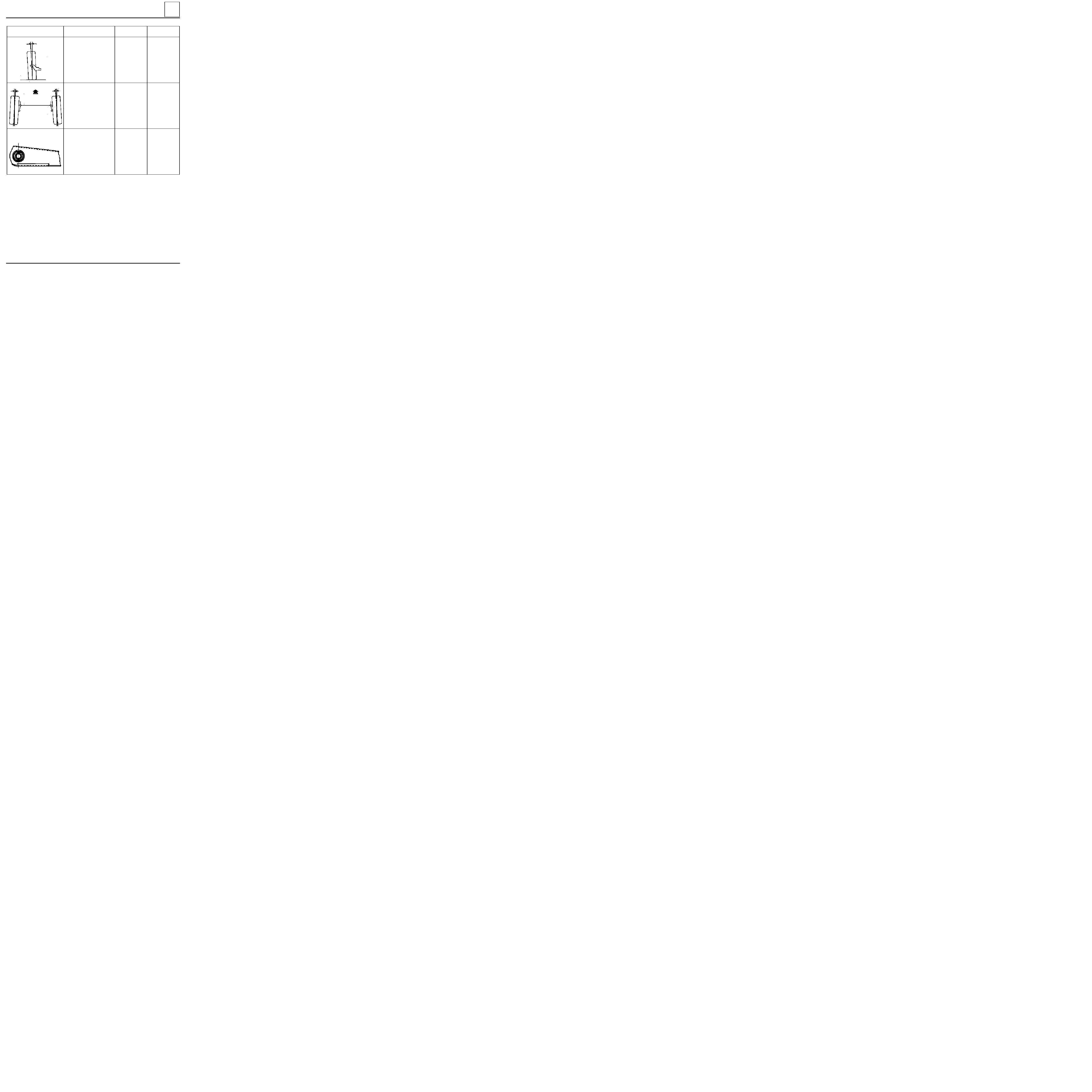
LIFTING
Underbody lifts
02
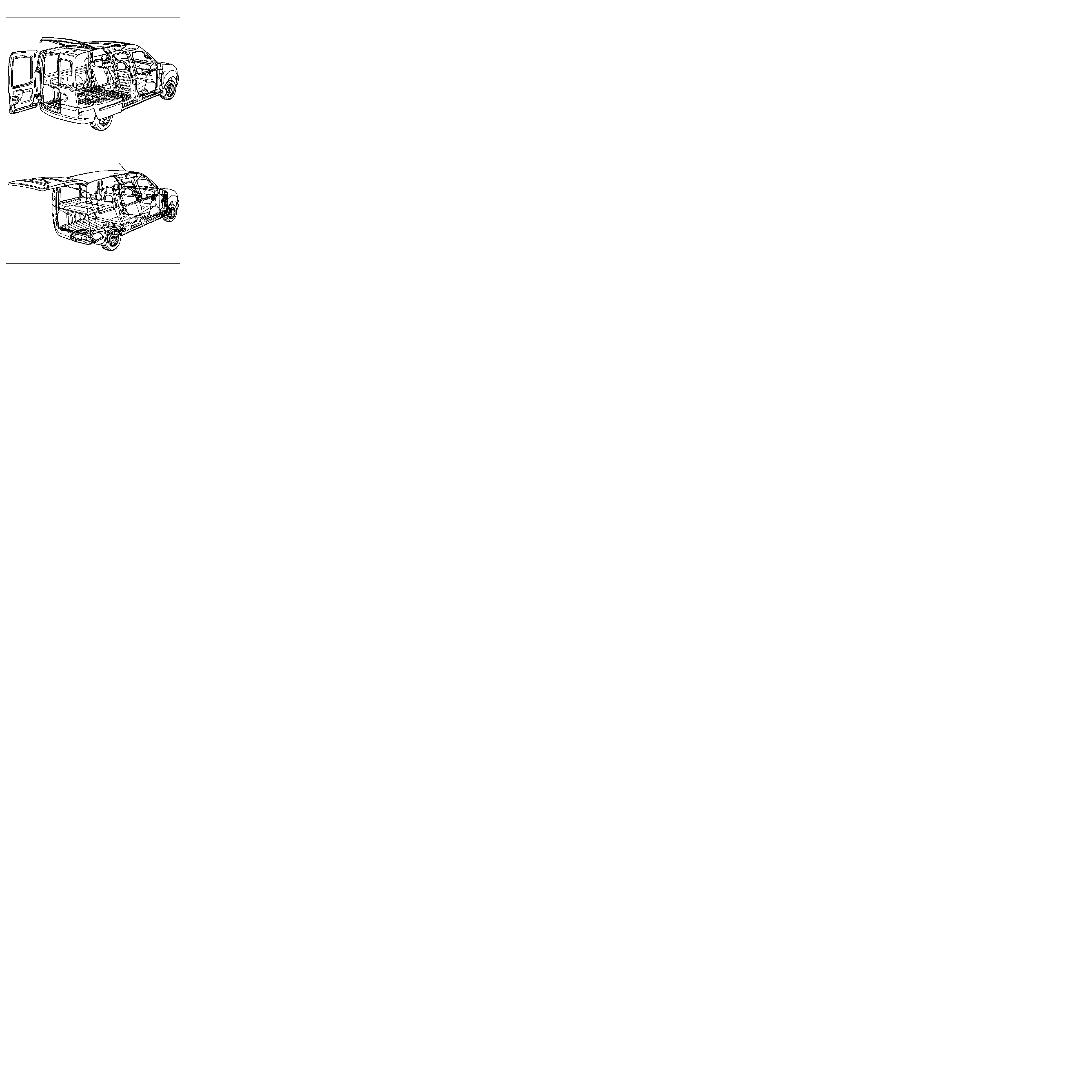
SAFETY INSTRUCTIONS
Various cases have to be considered:
1 -
REMOVING COMPONENTS
As a general rule, never use a 2 post lift whenever
a four post lift can be used.
If this is not possible, place the lifting pads
beneath the underbody flange at the level of the
tool kit jack supports.
98703S
F R O N T
98704S
REAR
These must be positioned level with the tool kit
jack supports. They must slot into the openings in
the underbody flanges.
2 -
REMOVING - REFITTING THE ENGINE AND
TRANSMISSION ASSEMBLY
In this particular case, the vehicle body must be
secured to the arms of the 2 post lift using special
pads.
Company FOG
Part Number FOG 449 8111 - 449 8411
or
Company CHEMICO
Part Number 39 2550 0001
or
Company SCHENCH
Part Number 776 684
02-2
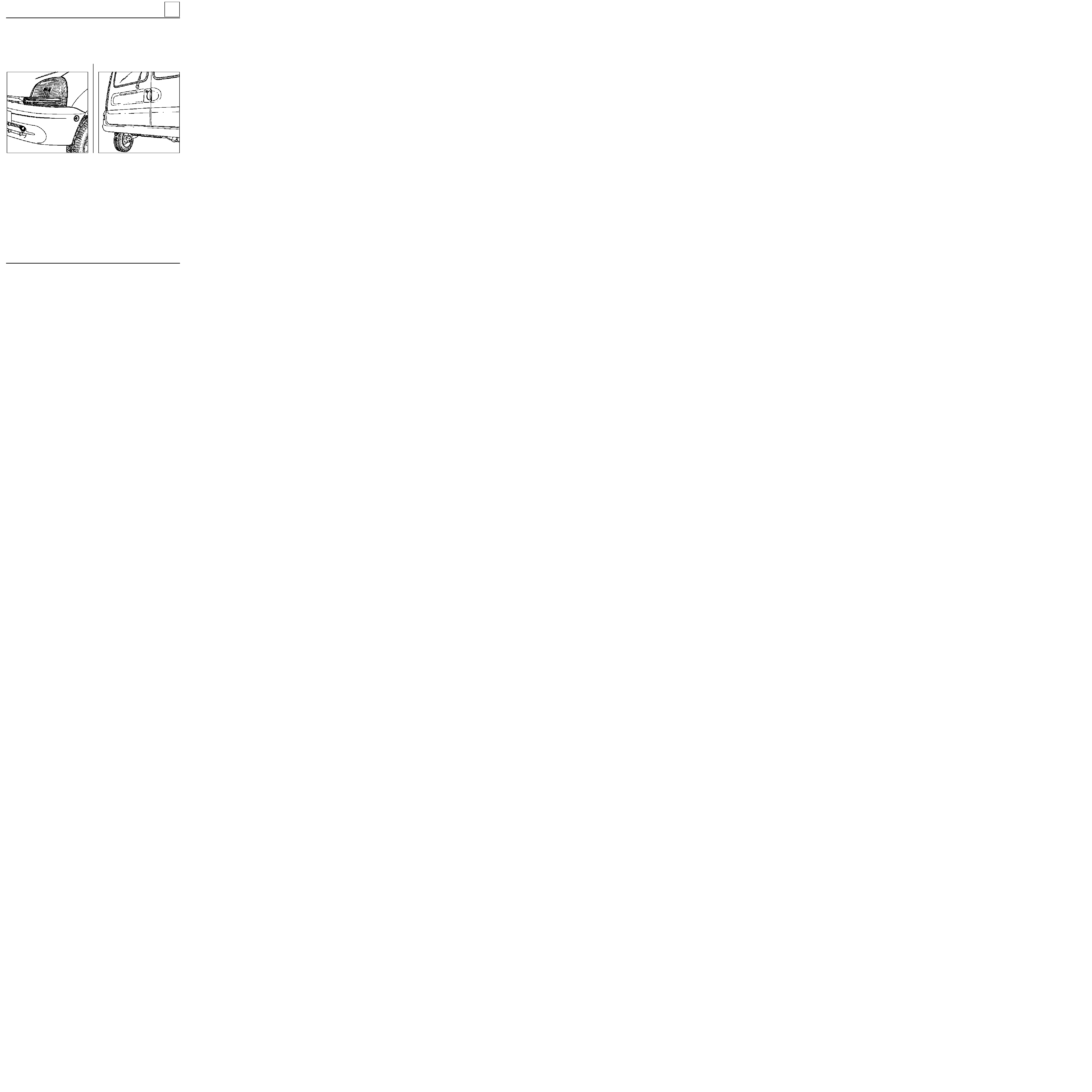
TOWING
All types
F R O N T
03
OBSERVE THE LEGAL TOWING REQUIREMENTS OF THE COUNTRY YOU ARE IN.
NEVER USE THE DRIVESHAFTS AS ATTACHMENT POINTS.
The towing points may only be used for towing the vehicle on the road. They should never be used for remo-
ving the vehicle from a ditch or for any other similar breakdown operation or to lift the vehicle, either direct-
ly or indirectly.
REAR
13366S
13189S
03-1

DESCRIPTION
PACKAGING
PART NUMBER
1 kg tin
100 g tube
80 ml tube
180 g sachet
Aerosol
77 01 421 145
77 01 028 179
77 01 422 307
77 01 366 100
77 01 422 308
LUBRICANTS
LUBRICANTS CONSUMABLES
Packaging
04
•
MOLYKOTE "BR2"
for main bearing journal faces, thrust pad
guide tubes, clutch fork pads, lower suspension
arm bearings, torsion bar splines, steering box,
driveshaft splines
•
MOLYKOTE "33 Medium"
tubular rear axle rings,
anti-roll bar rings
•
ANTI-SEIZE
(high temperature grease) Turbo etc.
•
"MOBIL CVJ" 825 Black star
or MOBIL EXF57C
for driveshaft joints
•
MULTIPURPOSE LUBRICANT
wheel sensor
• Perfect-seal "LOWAC"
coating fluid for seals
• Mastic
for sealing exhaust pipe unions
•
RHODORSEAL 5661
•
HARDENER KIT (RHODORSEAL 5661)
for bearing cap lateral seals
• AUTO joint blue
sealing paste
100 g tube
1.5 kg tin
100 g tube
kit
100 g tube
77 01 417 404
77 01 421 161
77 01 421 042
77 01 404 452
77 01 421 080
77 01 396 227
MECHANICAL SEALANTS
04-1

DESCRIPTION
PACKAGING
PART NUMBER
24 cc bottle
24 cc bottle
24 cc bottle
50 cc bottle
77 01 394 070
77 01 394 071
77 01 394 072
77 01 400 309
ADHESIVES
LUBRICANTS CONSUMABLES
Packaging
04
•
"LOCTITE - FRENETANCH"
stops bolts slackening and allows them to be
released
•
"LOCTITE - FRENBLOC"
locks bolts
•
"LOCTITE SCELBLOC"
for bonding bearings
•
"LOCTITE AUTOFORM"
for bonding the flywheel to the crankshaft
LUBRICANT CLEANING AGENTS
150 g aerosol
300 ml aerosol
355 ml can
500 ml aerosol
Aerosol
400 ml aerosol
77 01 408 464
77 11 171 437
77 01 423 189
77 01 408 466
77 01 405 952
77 11 170 801
•
"NETELEC"
unseizes, lubricates
• Carburettor cleaner
• Injector cleaner
•
Super-concentrated unseizing agent
•
"DECAPJOINT " (FRAMET)
for cleaning the
gasket faces of aluminium cylinder heads
• Brake cleaner
MECHANICAL SEALANTS
77 01 422 750
77 01 421 162
77 11 143 071
100 g tube
24 ml syringe
Aerosol
• AUTO joint grey
sealing paste
•
LOCTITE 518
for sealing the gearbox housing
• Leak detector
04-2

DESCRIPTION
PACKAGING
PART NUMBER
LUBRICANTS CONSUMABLES
Packaging
04
•
"CIRCUIT PLUS"
varnish for repairing heated screens
•
"CONTACT PLUS"
varnish for repairing rear screen supply termi-
nals
Bottle
Kit
77 01 421 135
77 01 422 752
VARNISHES
BRAKES
• Brake fluid
0.5 l bottle
DOT4
77 01 421 940
04-3
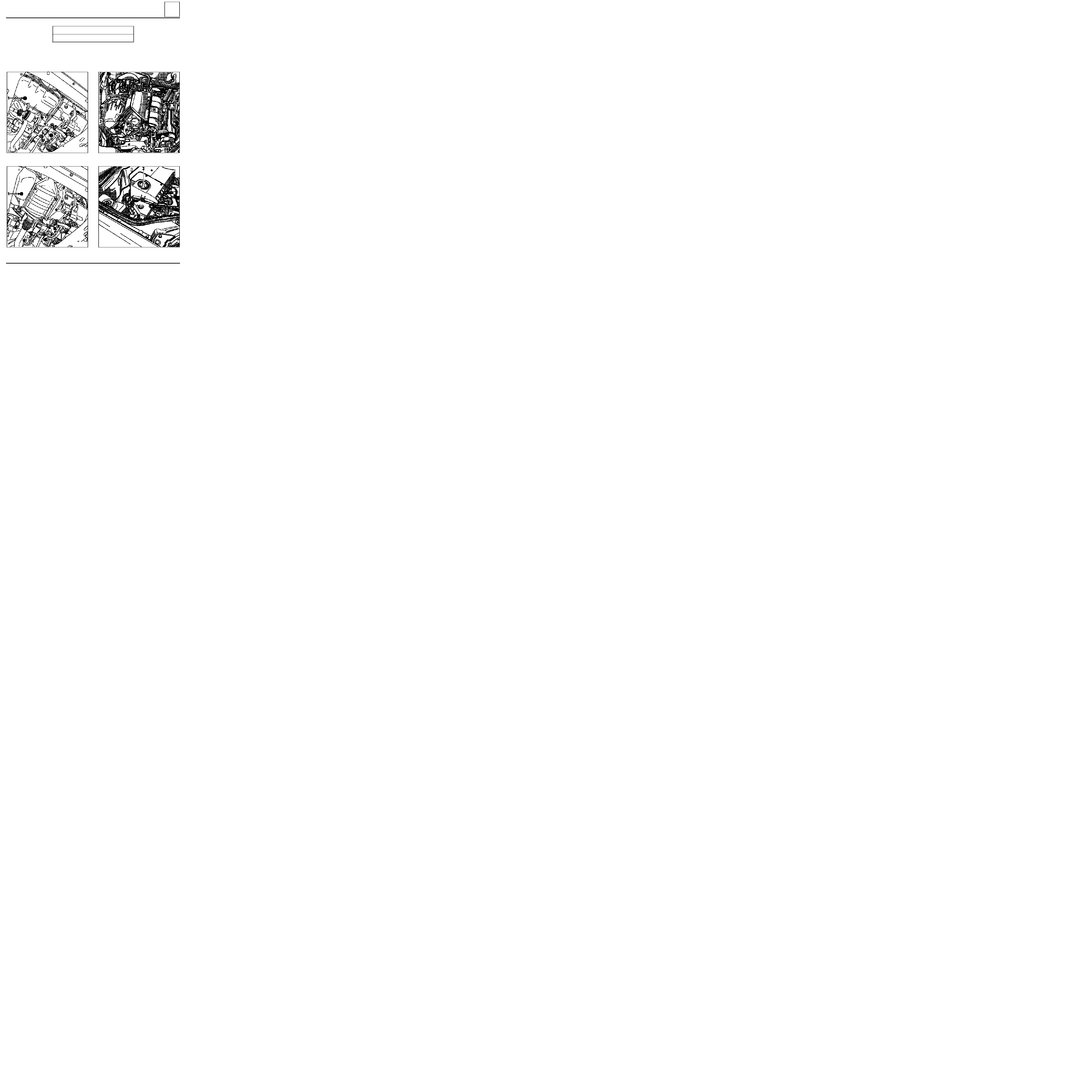
DRAINING - FILLING
Engine
E7J ENGINE
05
D7F ENGINE
TOOLING REQUIRED
Engine drain plug spanner
DRAINING
: plug (1)
13367R
FILLING
: plug(2)
13369R
12560R
13357R
05-1

DRAINING - FILLING
Engine
05
F8Q ENGINE
DRAINING:
plug (1)
FILLING:
plug (2)
13368R
13358R
05-2
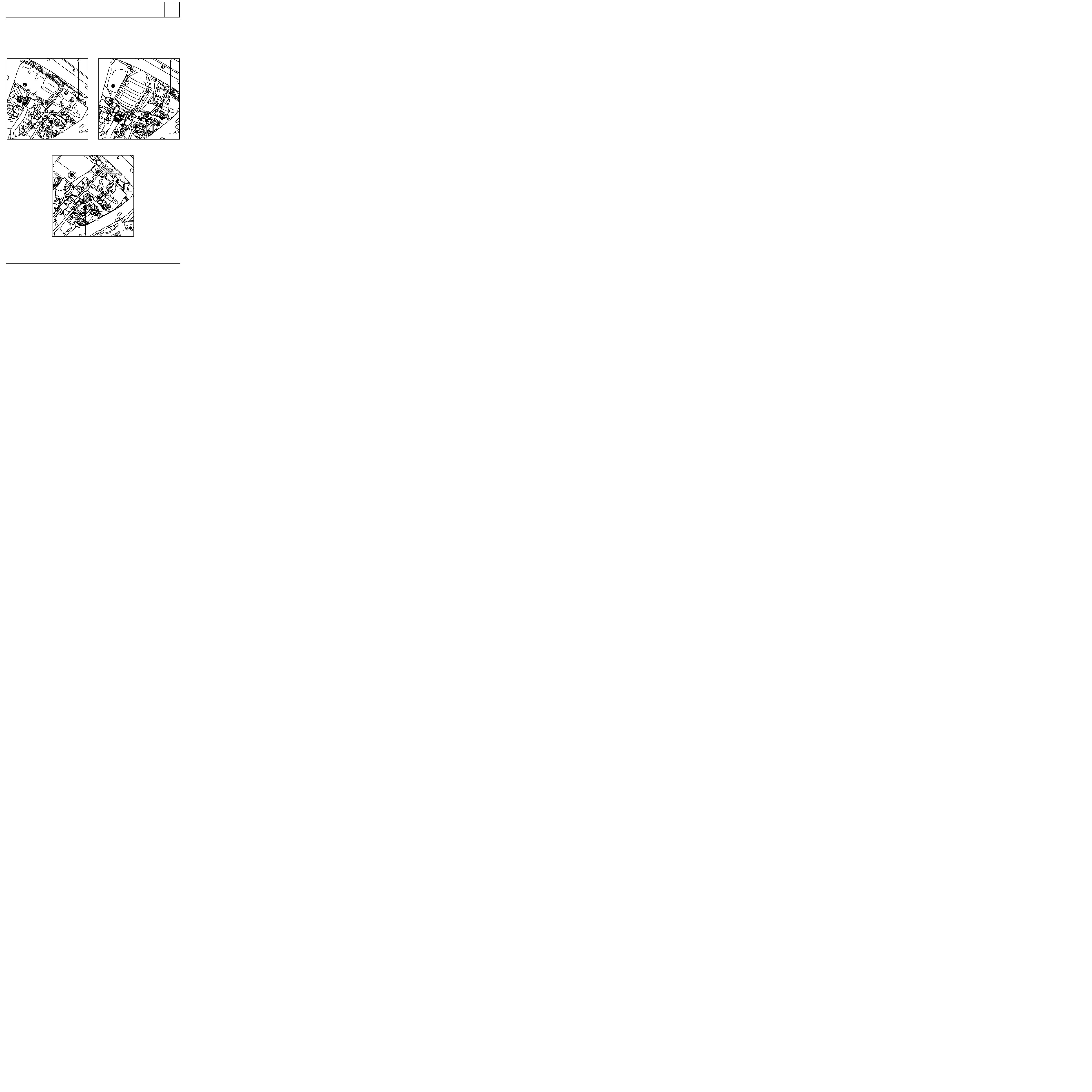
DRAINING - FILLING
Gearbox
05
DRAINING:
plug (1)
FILLING:
plug (2)
D7F ENGINE
13369R1
E7J ENGINE
13367R1
F8Q ENGINE
13368R1
05-3

DRAINING - FILLING
Power assisted steering
05
CHECKING THE LEVEL
POWER ASSISTED STEERING PUMP LEVEL
For topping up or filling, use
ELF RENAULTMATIC
D2 or MOBIL ATF 220 oil
.
The level, when correct, should be visible between
the
MIN
and
MAX
marks on the reservoir (1).
D7F - E7J - F8Q ENGINES
12422R1
05-4

VALUES AND SETTINGS
Dimensions
(1) Unladen
(2) Laden
07
12333R
Dimensions in metres
07-1
VALUES AND SETTINGS
Capacity - Grades
07
Components
When
draining
3,5
3.7 (1)
2.7
2.9 (1)
E.E.C. country
Other countries
Capacity
in litres
(approx.)*
Grade
Petrol engine
(oil)
D7F
E7J
0
°
C
+30
°
C
-30
°
C
+10
°
C +20
°
C
-20
°
C
-10
°
C
-15
°
C
+25
°
C
C C M C - G 4
15W40-15W50
A C E A A 2 - 9 6 / A 3 - 9 6
15W40-15W50
C C M C - G 5
10W30-10W40-10W50
ACEA
A2-96/A3-96 10W30-10W40-10W50
C C M C - G 5
5W30
A C E A A 2 - 9 6 / A 3 - 9 6
5W30
C C M C - G 5
5W40-5W50
A C E A A 2 - 9 6 / A 3 - 9 6
5W40-5W50
API SH 10W40
API SH 10W30
0
°
C
+30
°
C
-30
°
C
+10
°
C +20
°
C
-20
°
C
-10
°
C
-15
°
C
API SH 5W30
API SH 15W40
* Check with dipstick
(1) After replacing the oil filter
07-2
VALUES AND SETTINGS
Capacity - Grades
07
When
draining
4.7
5.2 (1)
E.E.C. country
Other countries
Diesel engine
(oil)
F8Q
0
°
C
+30
°
C
-30
°
C
+10
°
C +20
°
C
-20
°
C
-10
°
C
-15
°
C
+25
°
C
C C M C - P D 2
15W40
ACEA B2-96/B3-96
15W40
C C M C - P D 2
10W40
ACEA B2-96/B3-96
10W40
C C M C - P D 2
5W30
ACEA B2-96/B3-96
5W30
C C M C - P D 2
5W40
ACEA B2-96/B3-96
5W40
API CF 10W30
0
°
C
+30
°
C
-30
°
C
+10
°
C +20
°
C
-20
°
C
-10
°
C
-15
°
C
+15
°
C
API CF 15W40
API CF 10W40
* Check with dipstick
(1) After replacing the oil filter
Components
Capacity
in litres
(approx.)*
Grade
07-3

VALUES AND SETTINGS
Capacity - Grades
07
3.4
Manual gearbox
Components
Capacity
in litres
Grade
Notes
JB1
3.4
Brake circuit
Brake fluids must be approved by the Technical
Department
SAE J 1703
and DOT 4
All countries: TRANSELF TRX 75 W 80 W
( API GL5 or MIL-L 2105 C or D standards)
Normal : 0.7
ABS : 1
Fuel tank
approx.
50
Unleaded
petrol/diesel
JB3
Separate
reservoir
1.1
Cooling
circuit
D7F
E7J
F8Q
-
GLACÉOL RX
(type D)
Only add coolant of the
same type
5
5.5
7.4
Power assisted
steering
-
ELF RENAULT MATIC D2
or
MOBIL ATF 220
-
07-4
VALUES AND SETTINGS
Belt tension
07
96601R
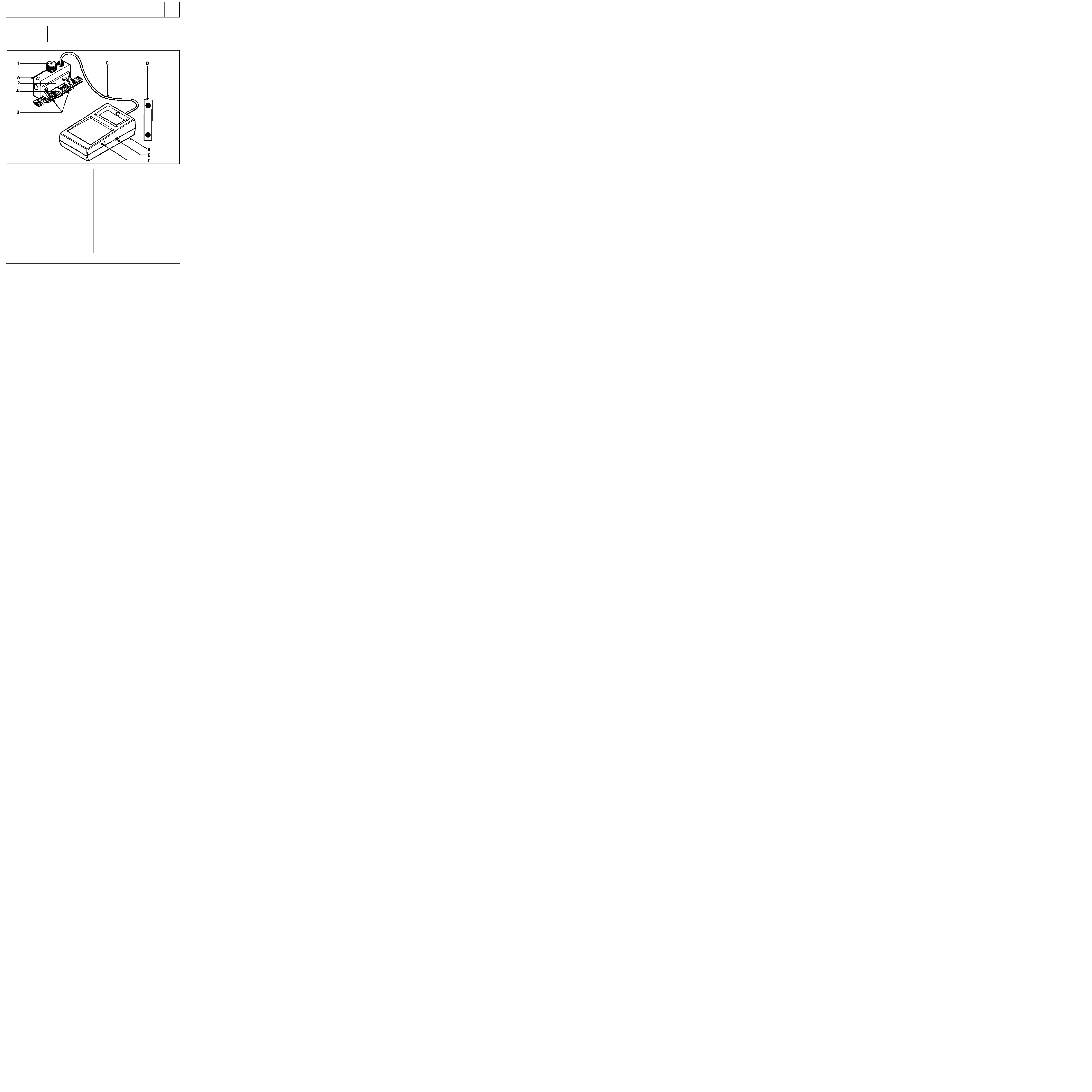
SPECIAL TOOLING REQUIRED
Mot.
1273
Tool for checking belt tension
A Sensor
B Display
C Connecting cable
D Calibration checking plate
Principle
The sensor, through the presser button (1), the
presser (2) and the outer pads (3), applies a
constant force to the belt.
The reaction from the belt is measured using a
test piece (4) fitted with strain gauges.
Any movement on the gauges creates a variation
in their electrical resistance. This variation, once it
has been converted by the device, is displayed on
the display in SEEM units (US).
Calibrating the device
The device is set in the factory; however it must be
recalibrated every six months.
Procedure
Resetting the zero:
- switch on the device (button E) with the presser
button (1) face down,
- if 0 is displayed, do not touch anything,
- if nothing is displayed, check the condition of
the 9 volt battery in the device ,
- if a value other than 0 is displayed, adjust screw
(F) until 0 is obtained.
07-5

VALUES AND SETTINGS
Belt tension
07
Checking the calibration
Switch on the device (button E).
Position the calibration spring plate (Z) on the sensor as shown on the diagram (control value engraved to-
wards the top, (A) minimum value, (B) maximum value).
Tighten the presser button (1) until it goes "CLICK - CLICK - CLICK".
Check that a value X between the values (A and B) (A
≤
X
≤
B) is displayed.
NOTE:
it may be necessary to perform several preliminary tests in order to obtain the correct value.
If the correct value if still not obtained after several attempts, contact SEEM.
NOTE :
each device has its own calibration spring plate and they are not interchangeable.
96602R
1 Knurled button (presser)
A
B
Z Calibration plate
Calibration plate control value
SEEM
Contact your After Sales Head Office for further
information.
GENERAL INSTRUCTIONS:
_ Never refit a belt which has been removed, re-
place it.
- Never retighten a belt for which the tension
reading is between the fitting value and the
minimum operating value.
- When checking, if the tension is below the mi-
nimum operating value, change the belt.
07-6

VALUES AND SETTINGS
Accessories belt tension
07
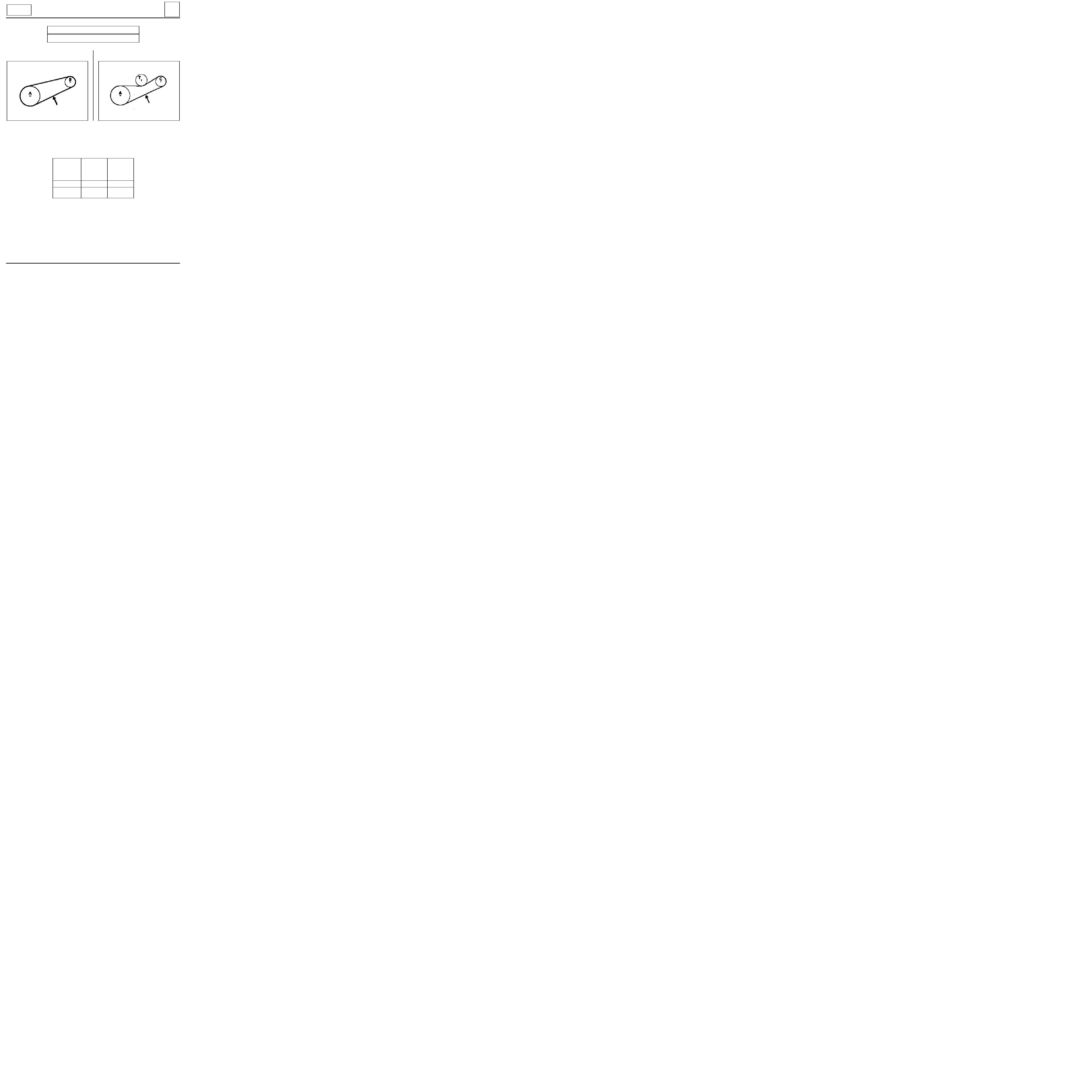
RIBBED BELT
Tensioning process
Engine cold (ambient temperature).
Fit the new belt.
Position the sensor of Mot. 1273.
Turn the wheel of the sensor until it disengages (three "CLICKS").
Tension the belt until the recommended fitting value is displayed on Mot. 1273 .
Lock the tensioner, check it, adjust the value.
Turn the crankshaft over three times.
Check that the tension value is within the fitting tension tolerance, otherwise readjust it.
NOTE :
Never refit a belt which has been removed.
Replace the belt if the tension is below the minimum operating tension.
Small cuts or cracks
do not mean that the belt has to be replaced.
07-7
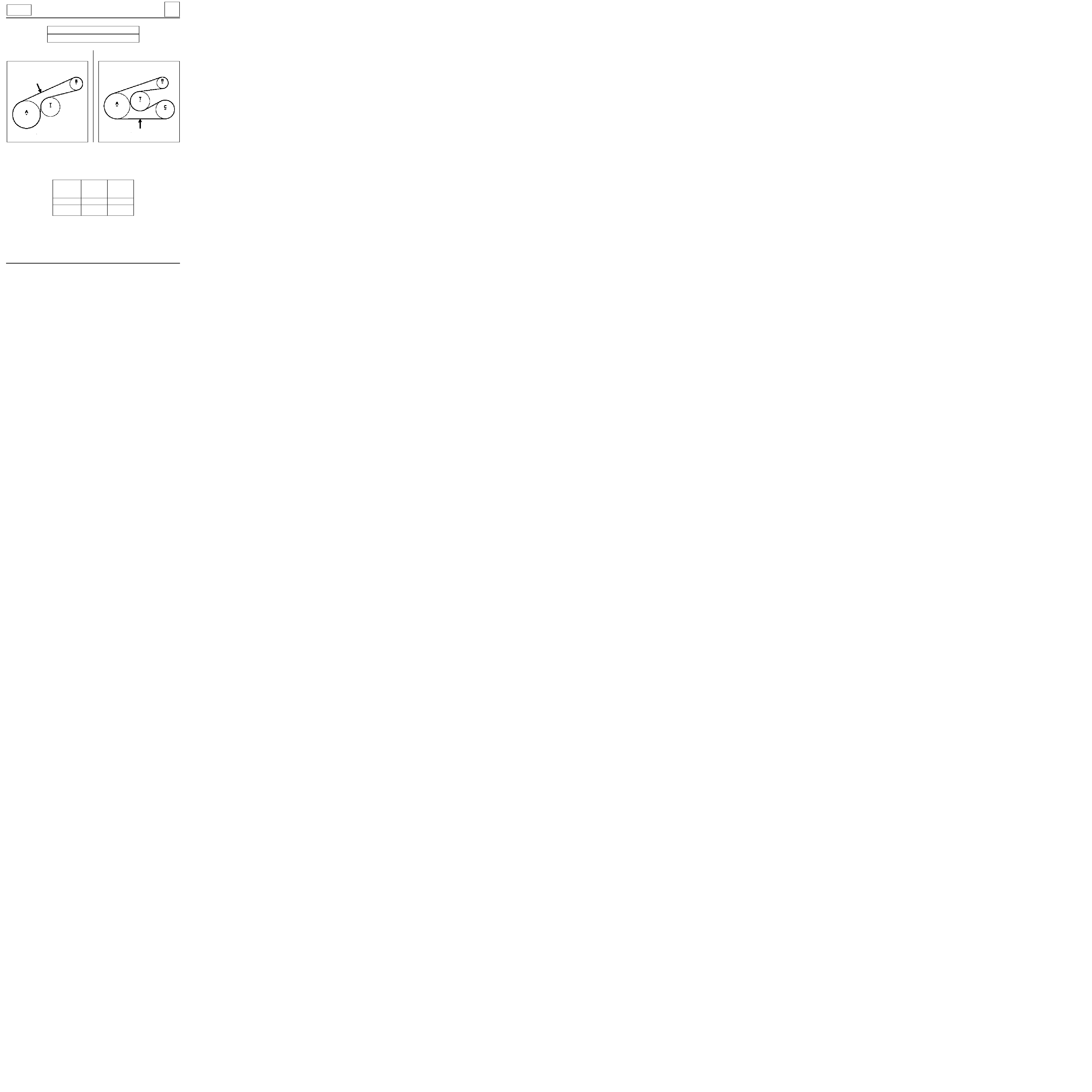
VALUES AND SETTINGS
Accessories belt tension
07
10071R2
A
Crankshaft
B
Alternator
C
Power assisted steering pump
T
Tensioner
→
Point for checking belt tension
ALTERNATOR BELT
D7F
ENGINE
Tension
(US=SEEM unit)
Alternator
belt,
multitooth
Power assisted
steering belt,
multitooth
Fitting
102
±
7
96
±
5
Minimum
operating
53
43
POWER ASSISTED STEERING BELT
SPECIAL TOOLING REQUIRED
Mot.
1273
Tool for checking the belt tension
97267R4
07-8

VALUES AND SETTINGS
Accessories belt tension
07
13511R
A
Crankshaft
B
Alternator
C
Power assisted steering pump
T
Tension wheel
→
Point for checking belt tension
ALTERNATOR BELT
E7J
ENGINE
Tension
(US=SEEM unit)
Alternator
belt,
multitooth
Power assisted
steering belt,
multitooth
Fitting
101
±
6
106
±
6
Minimum
operating
52
59
SPECIAL TOOLING REQUIRED
Mot.
1273
Tool for checking the belt tension
13510R
Bolt A: alternator belt tension
Bolt B: power assisted steering belt tension
NOTE :
Tighten the nuts of bolts (A) and (B) after
adjusting the tension.
13363R1
POWER ASSISTED STEERING BELT
07-9
VALUES AND SETTINGS
Accessories belt tension
07
13512R
A
Crankshaft
B
Alternator
C
Power assisted steering pump
T
Tension wheel
→
Point for checking belt tension
ALTERNATOR BELT
F8Q
ENGINE
Tension
(US=SEEM unit)
Alternator
belt,
multitooth
Power assisted
steering belt,
multitooth
Fitting
115
±
5
116
±
6
Minimum
operating
70
68
SPECIAL TOOLING REQUIRED
Mot.
1273
Tool for checking the belt tension
13509R
ALTERNATOR AND POWER ASSISTED STEERING
BELT
07-10
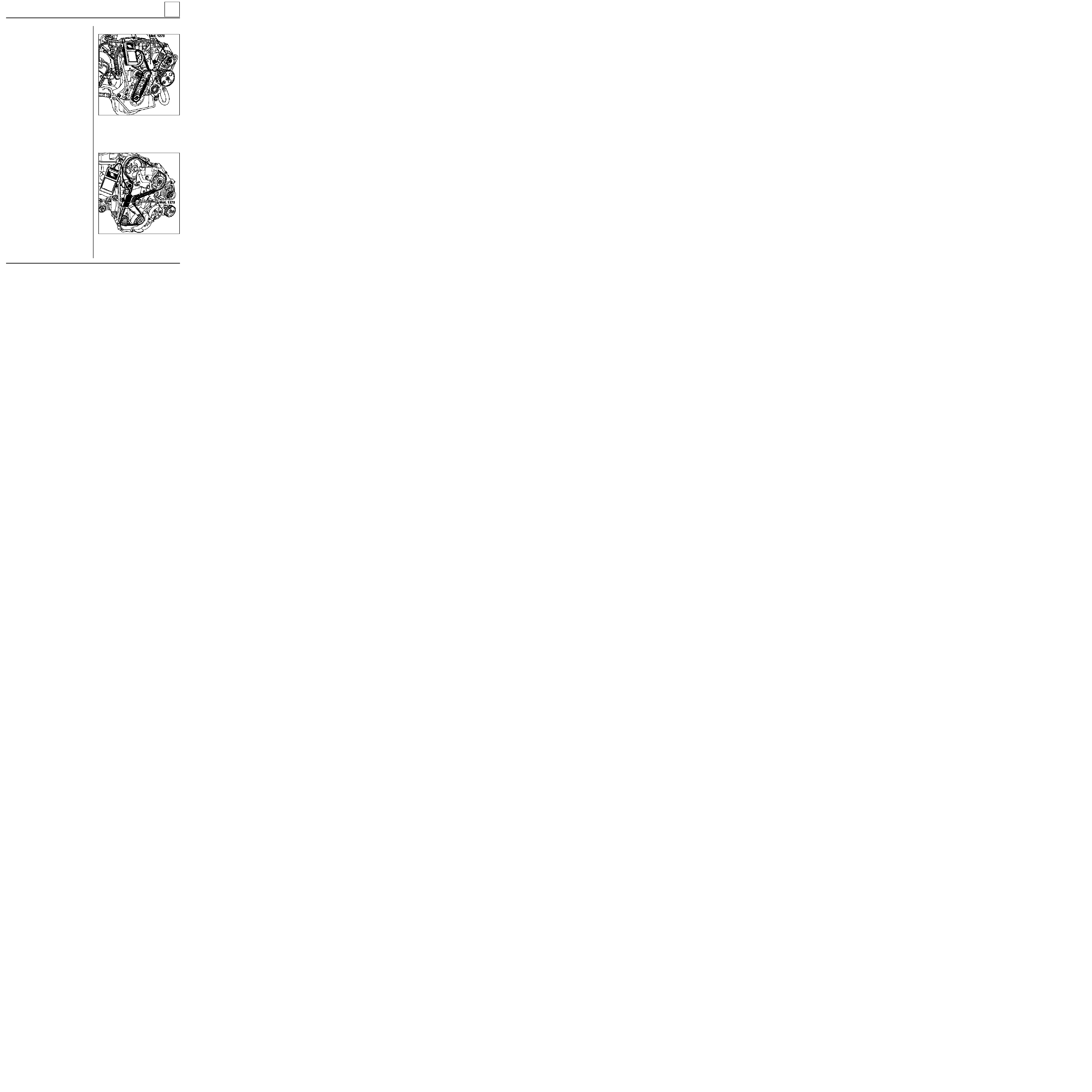
VALUES AND SETTINGS
Timing belt tension
07
13361R
E7J engine
Tensioning process
Engine cold (ambient temperature).
Fit the new belt.
Position the sensor of Mot. 1273.
Turn the wheel of the sensor until it disengages
(three "CLICKS").
Tension the belt until the recommended fitting
value is displayed on Mot. 1273.
Lock the tensioner, check it and adjust the value.
Turn the crankshaft over at least three times .
Check that the tension value is within the fitting
tension tolerance (
±
10%), otherwise readjust it,
repeating the operations described above.
NOTE :
- For the F8Q engine, remove the pin Mot 1054
before fitting the sensor of tool Mot 1273 and
press hard on the section of belt between the
intermediate shaft sprocket (or idle sprocket)
and the tension wheel,
then make the measu-
rement.
- Never refit a belt which has been removed.
- Replace the belt if the tension is below the mi-
nimum operating tension
.
D7F engine
There are special features for tensioning the ti-
ming belt: refer to section 11.
Belt tension (in SEEM units)
Fitting: 30 U.S.
Minimum operating : 26 U.S.
F8Q engine
13094R
Belt tension (in SEEM units)
Fitting : 29 U.S.
Minimum operating : 25 U.S.
07-11
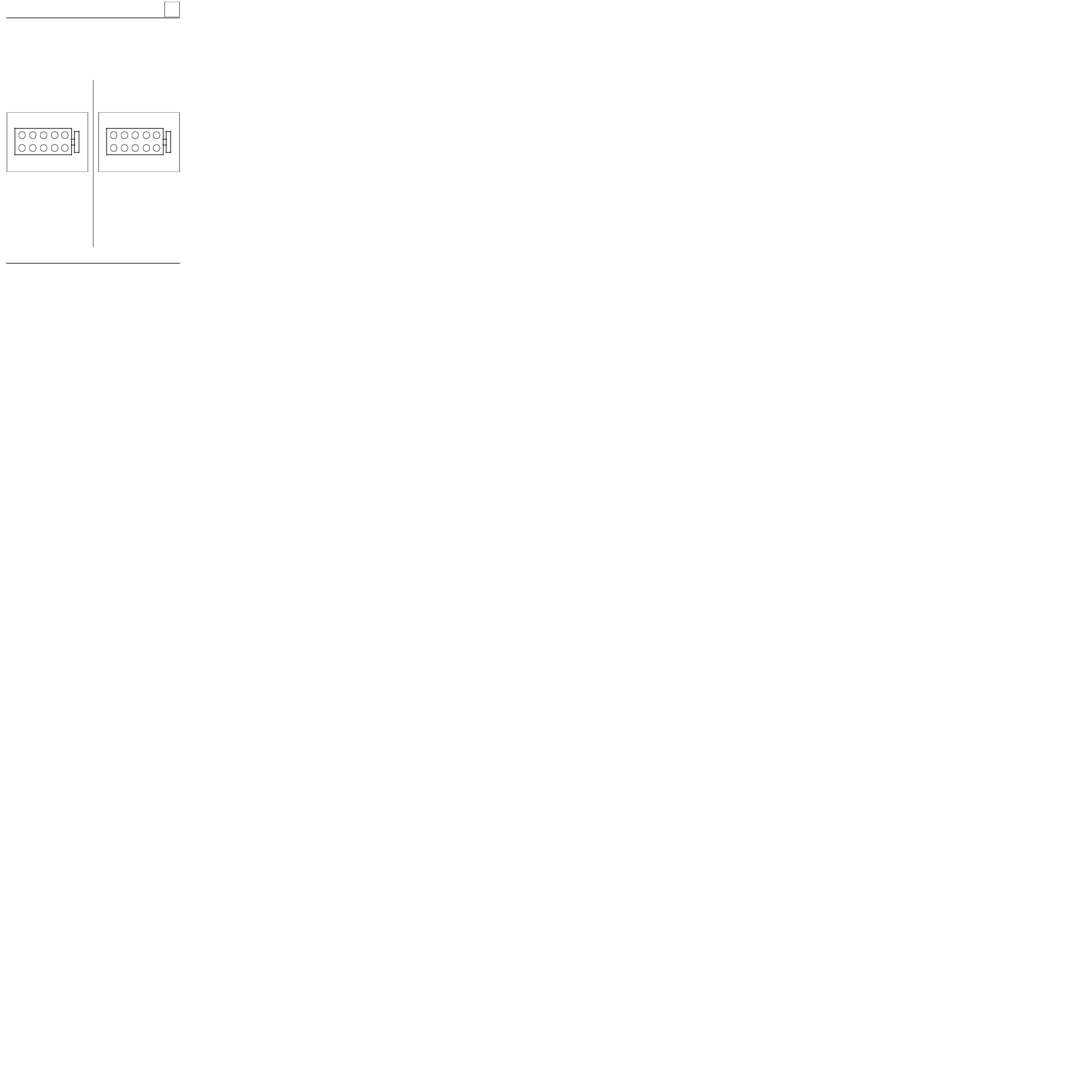
VALUES AND SETTINGS
Tightening the cylinder head
07
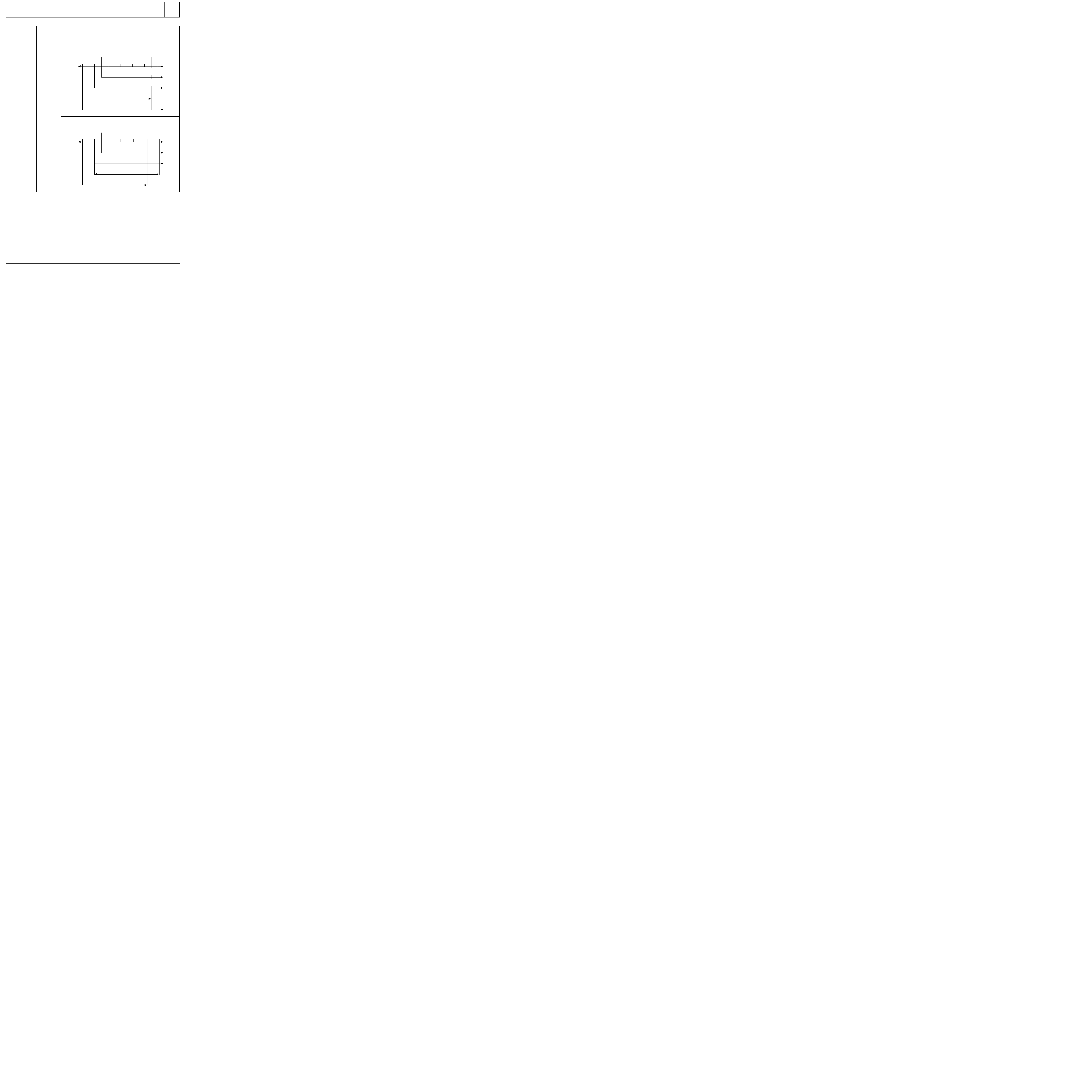
METHOD FOR TIGHTENING THE CYLINDER HEAD
REMINDER:
In order to ensure that the bolts are correctly tightened, use a syringe to remove any oil which may be in the
cylinder head mounting holes.
All the cylinder head bolts must be systematically renewed after removal.
There is no cylinder head retightening operation.
Using engine oil, lubricate the threads and under the heads of the bolts.
2
7
6
1 0
1
8
5
9
4
3
D7F ENGINE
Preseating the gasket
Tighten all the bolts to 2 daN.m, then angle tigh-
ten to 90
°
in the order shown below.
Wait 3 minutes settling time.
Tightening the cylinder head:
- The cylinder head tightening is carried out in
stages and the following procedure is applied
successively to bolts 1-2 then 3-4, 5-6, 7-8 and 9
-10.
- Slacken bolts 1-2 until they are completely free.
- Tighten bolts 1-2 to 2 daN.m, then turn
through an angle of 200
°
.
- Repeat the slackening and tightening opera-
tions for bolts 3-4, 5-6, 7-8 and 9-10.
90775S
E7J ENGINE
Preseating the gasket
Tighten all the bolts to 2 daN.m, then angle tigh-
ten to 97
°
±
2
°
in the order shown below.
2
7
6
1 0
1
8
5
9
4
3
90775S
Wait 3 minutes settling time.
Tightening the cylinder head:
- The cylinder head tightening is carried out in
stages and the following procedure is applied
successively to bolts 1-2 then 3-4, 5-6, 7-8 and 9
-10.
- Slacken bolts 1-2 until they are completely free.
- Tighten bolts 1-2 to 2 daN.m, then turn
through an angle of 97
°
±
2
°
.
- Repeat the slackening and tightening opera-
tions for bolts 3-4, 5-6, 7-8 and 9-10
07-12

VALUES AND SETTINGS
Tightening the cylinder head
07
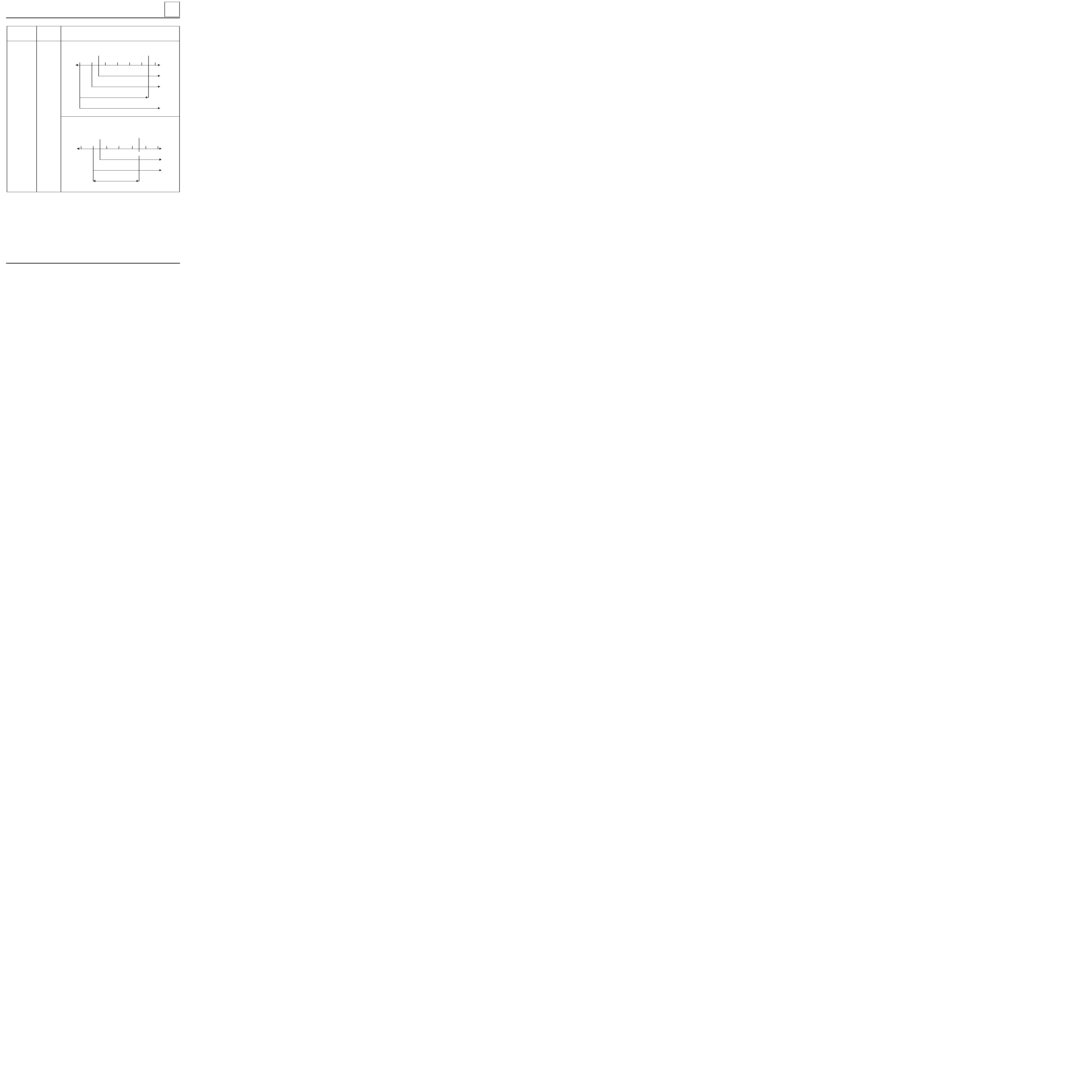
2
7
6
1 0
1
8
5
9
4
3
F8Q ENGINE
Preseating the gasket
Tighten all the bolts to 3 daN.m then angle tigh-
ten to 80
°
±
4
°
in the order shown below.
Wait 3 minutes settling time.
Tightening the cylinder head:
- The cylinder head tightening is carried out in
stages and the following procedure is applied
successively to bolts 1-2, then 3-4, 5-6, 7-8 and
9-10
.
- Slacken bolts 1-2 until they are completely free.
- Tighten bolts 1-2 to 2.5 daN.m, then angle tigh-
ten to 213
°
±
7
°
.
- Repeat the slackening and tightening opera-
tions for bolts 3-4, 5-6, 7-8 and 9-10.
90775S
07-13

VALUES AND SETTINGS
Tyres and wheels
07
Vehicle
Wheel rim
Tyres
Cold inflation pressure
(in bars) (1)
Front
Rear
FC0X
KC0X
5 B 13
5 B 13
5.5 J 14
165/70 R 13 C 88/86
165/70 R 13 83 (2)
165/70 R 14
2.8
2.6
2.4
3.6
2.9
3.0
(1) Fully laden and motorway use.
Tightening torque of wheel nuts : 9 daN.m
Rim run-out: 1.2 mm
(2) Reinforced tyre.
07-14

VALUES AND SETTINGS
Brakes
07
Vehicle
Drum diameters or disc thicknesses (in mm)
Front
Normal
Min.
Rear
Normal
Max. (1)
Max. disc run-out
(in mm)
Front
Rear
FC0X
KC0X
20
17.7
normal
payload
203.2
increased
payload
228.3
normal
payload
204.45
increased
payload
229.5
0.07
-
(1) Drum: maximum wear diameter
(1) Leading brake shoe.
(2) Trailing brake shoe.
(3) Increased payload.
Vehicle
Lining thicknesses (in mm) (including backing)
Front
Brand new
Minimum
Rear
Brand new
Minimum
Brake fluid
FC0X
KC0X
17.8
5.5
With ABS
4.6 (1)
3.15 (2)
No ABS
4.2 (1)
2.8 (2)
2
SAE J1703
DOT 4
FC0X (3)
KC0X (3)
17.8
5.5
With ABS
4.8
No ABS
4.5
2
SAE J1703
DOT 4
07-15
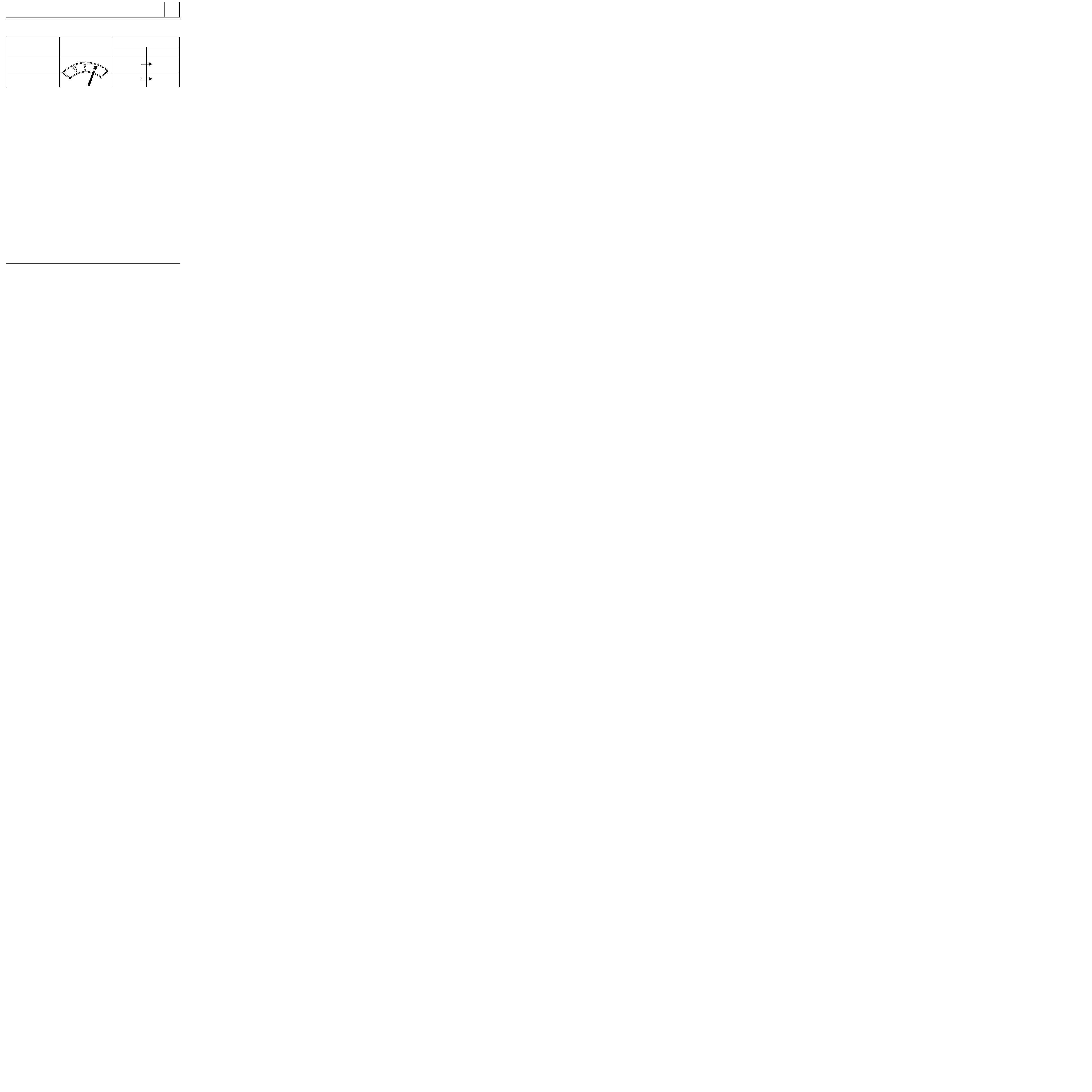
VALUES AND SETTINGS
Brake limiter
07
Vehicle
Fuel tank
(driver on board)
Test pressure (1) (in bars)
Front
Rear
FC0X
KC0X
normal payload
100
35.4
FC0X
KC0X
increased payload
100
38
BRAKING PRESSURE
+ 8
0
90966S
+ 8
0
(1) The test is performed using two pressure gauges in an X arrangement.
07-16

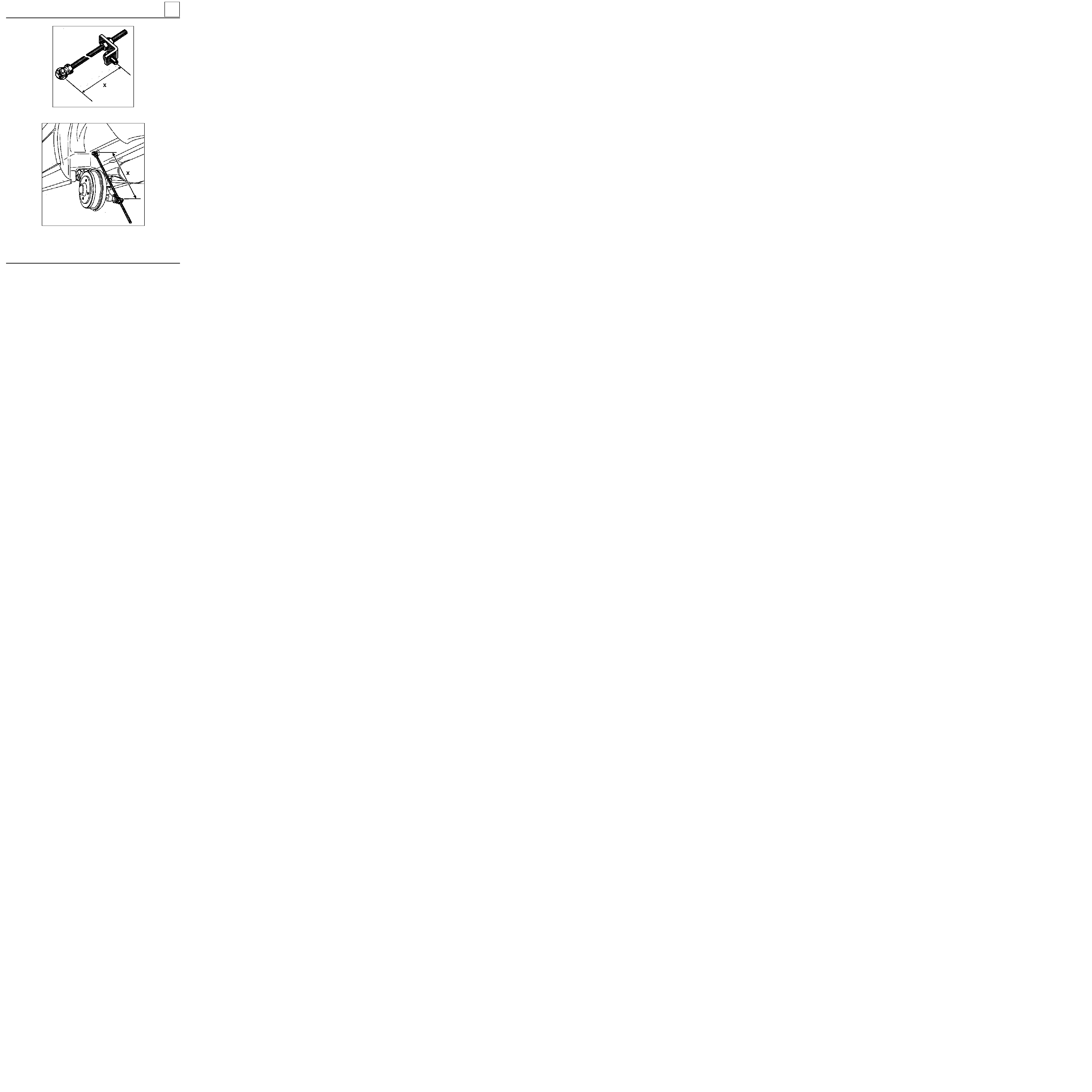
VALUES AND SETTINGS
Underbody heights
07
Vehicle
At the front
H1 - H2 = ... mm
At the rear
H4 - H5 = ... mm
Dimension X (in mm)
R-H and L-H
FC0X
KC0X
73.5
- 60.5 (1)
- 54.1 (2)
402 (1)
430 (2)
Tolerance :
±
7.5 mm
The difference between the right-hand side and the left-hand side of the same axle of a vehicle must not ex-
ceed 5 mm, the driver’s side always being the higher.
Any adjustment of the underbody height means that the brake limiter and the headlights must be adjusted.
(1) Increased payload.
(2) Standard payload.
07-17

VALUES AND SETTINGS
Underbody heights
07
12333R3
Dimension H5 is measured from the axis of the
suspension bar.
88636-4R
MEASUREMENT POINTS
07-18
VALUES AND SETTINGS
Underbody heights
07
88637R
88576R
07-19
H1 - H2 =
7 mm
H1 - H2 =
74 mm
H1 - H2 =
98 mm
H1 - H2 = 164 mm
H1 - H2 =
7 mm
H1 - H2 =
74 mm
H1 - H2 =
98 mm
H1 - H2 = 164 mm
H5 - H2 =
97 mm
H5 - H2 = 117 mm
H5 - H2 = 137 mm
H5 - H2 = 157 mm
81603S1
93011-1S
93014-1S
93013-1S
93012-1S
VALUES AND SETTINGS
Values for checking the front axle geometry
07
UNLADEN
NOT ADJUSTABLE
NOT ADJUSTABLE
NOT ADJUSTABLE
CAMBER
VALUES
C A S T O R
3
°
55’
3
°
25’
2
°
55’
2
°
25’
Maximum right/left
difference = 1
°
1
°
12’
- 0
°
15’
- 0
°
29’
- 0
°
13’
Maximum right/left
difference = 1
°
A D J U S T M E N T
POSITION OF
FRONT AXLE
KINGPIN
8
°
05’
10
°
25’
11
°
01’
11
°
56’
Maximum right/left
difference = 1
°
PARALLELISM
RUBBER BUSHES
Adjustable by
rotating track
rod sleeves
1 turn= 30’
(3 mm)
(For 2 wheels)
toe-out
+ 0
°
10’
±
10’
+ 1 mm
±
1 mm
ANGLES
UNLADEN
-
-
±
30’
±
30’
±
30’
07-20
(For 2 wheels)
Toe-in
- 15’
±
10’
- 1,5 mm
±
1 mm
- 0
°
50’
±
15’
NOT ADJUSTABLE
93013-2S
93011-2S
81603S1
VALUES AND SETTINGS
Values for checking the rear axle geometry
07
UNLADEN
CAMBER
VALUES
PARALLELISM
ANGLES
UNLADEN
NOT ADJUSTABLE
UNLADEN
-
-
RUBBER BUSHES
POSITION OF
REAR AXLE
A D J U S T M E N T
07-21
Document Outline
- 01-SPECIFICATIONS
- 02-LIFTING
- 03-TOWING
- 04-LUBRICANTS CONSUMABLES
- 05-DRAINING - FILLING
- 07-VALUES AND SETTINGS
Wyszukiwarka
Podobne podstrony:
MR 325 KANGOO 3
MR 325 KANGOO 8
MR 325 KANGOO 6
MR 325 KANGOO 3
MR 325 KANGOO 8
MR 326 KANGOO 7
MR 326 KANGOO RX4 1
MR 326 KANGOO 6
MR 326 KANGOO 5
MR 326 KANGOO GV 4
więcej podobnych podstron