FM 23-23
D E P A R T M E N T O F T H E A R M Y F I E L D M A N U A L
ANTIPERSONNEL MINE
M18A1 AND M18
(CLAYMORE)
H E A D Q U A R T E R S , D E P A R T M E N T O F T H E A R M Y
J A N U A R Y 1 9 6 6
This copy is a reprint which includes
current pages from Changes 1 and 2.

FM 23-23
C2
C
HANGE
HEADQUARTERS
DEPARTMENT OF THE ARMY
N O . 2
WASHINGTON, D.C. 30 March 1973
ANTIPERSONNEL MINE, M18A1 and M18 (CLAYMORE)
FM 23-23, 6 January 1966, is changed as follows:
Page 2, para 3, line 13. The words “(knife-edge sight on later model)” is added after “slit/type
sight,”.
Page 2, para 3, line 15. The last sentence of paragraph 3 is changed to read: An instruction sheet
for the M18A1 mine is attached to the inside cover of the bandoleer. The instruction sheet which accom-
panies the M18A1 mine having the knife-edge sight is shown in figure 3.
TAGO-3366A
1
C2, FM 23-23
Page 3. Figure 1 is superseded.
2
C2, FM 23-23
Page 6. Figure 3 is superseded.
3

C2, FM 23-23
Page 8, para 7c(9), line 1. The words “Peepsight and arrows.” are changed to read “Sight and
arrows.”
Page 8, para 7a(9), line 2. The words “(or knife-edge sight)” are added after the word “peepsight”.
Page 9, para 7b(2), line 2. The word “assembly” is added after the word “cap”.
Page 9, para 7b(2). The following note is added:
Note. With mines of later manufacture, the M4 electrical blasting cap assembly is wound on a spool.
Page 11, paragraph 12 is superseded as follows:
12. Installation for Electrical Firing
a. Laying and Aiming.
(1) Laying.
(a) Check to see that the mine and all accessories (fig. 2) are in the bandoleer. Read the instruc-
tion sheet (fig. 3) attached inside the bandoleer cover before installing the mine.
(b) Remove the electrical firing wire leaving the mine and other accessories in the bandoleer.
Warning: During installation the M57 firing device must be kept in the possession of the man
installing the mine to prevent accidental firing by a second man.
(c) Secure the shorting plug end of the firing wire at the firing position. Place the bandoleer
on your shoulder and unroll the firing wire to the position selected for emplacing the mine.
Note. The instructor sheet which accompanies the M18A1 mine with slit-type peepsight indicates that the firing wire
can be unrolled from the mine or from the firing position; however, the firing wire should always be laid from the firing psition
to the mine emplacement.
(d) Remove the mine from the bandoleer; turn the legs rearward and then downward. Spread
each pair of legs about 45 degrees. One leg should protrude to the front and one to the rear of the
mine. Position the mine with the surface marked “FRONT TOWARD ENEMY” and the arrows on
top of the mine pointing in the direction of the enemy or the desired area of fire. On snow or extremely
soft ground the bandoleer may be spread beneath the mine for support.
(e) To prevent tipping in windy areas or when the legs cannot be pressed into the ground,
spread the legs to the maximum (about 180° so that the legs are to the front and rear of the mine.
A top view of the M18A1 antipersonnel mine is shown in figure 10.
(2) Aiming.
(a) Mines with slit-type peepsight.
1. Select an aiming point which is about 50 meters (150 feet) to the front of the mine and
about 2½ meters (8 feet) above the ground (fig. 11).
2. Position the eye about 15 centimeters (6 inches) to the rear of the sight. Aim the mine
by sighting through the peepsight. The groove of the sight should be in line with the aiming point.
The aiming point should be in the center of the desired area of coverage, and the bottom edge of the
peepsight should be parallel to the ground that is to be covered with the fragment spray.
(b) Mines with knife-edge sight.
1. Select an aiming point at ground level that is about 50 meters (150 feet) in front of the
mine.
2. Position the eye about 15 centimeters (6 inches) to the rear of the sight. Aim the mine
by alining the two edges of the sight with the aiming point (fig. 11.1).
b. Arming and Electrical Firing.
(1) Secure the firing wire about 1 meter behind the mine so it will not become misalined should
the firing wire be disturbed.
(2) Test the firing device, test set, and blasting cap assembly as described in paragraph 15.
4

C2, FM 23—23
Warning. Make certain that the combination shorting plug and dust cover is assembled to the
connector of the firing wire before proceeding with installation of the mine.
(3) Unscrew one of the shipping plug priming adapters from the mine. Slide the slotted end of the
shipping plug priming adapter (fig. 12) onto the firing wires of the blasting cap between the crimped
connections and the blasting cap. Pull the excess wire through the slotted end of the adapter until the
top of the blasting cap is firmly seated in the bottom portion of the shipping plug priming adapter.
Screw the adapter with blasting cap into the detonator.
Warning. Make certain that the face of the mine marked “Front Toward Enemy” and the
arrows on top of the mine point in the direction of the enemy.
(4) Recheck the aim of the mine. Camouflage the mine and, if possible, bury the firing wire to
protect it from fire and enemy detection. Make certain you have the bandoleer and other accessories
and then move back to the firing position.
Warning. The mine firing position should be in a foxhole or covered position at least 16
meters to the rear or the side of the emplaced mine.
(5) Before connecting the M57 firing device (fig. 5) to the firing wire, make certain that the safety
bail is in the SAFE position and that all friendly troops within 250 meters of the front and sides and
100 meters of the rear of the mine are under cover. Do not connect the firing device to the firing wire
until the actual time of firing.
(6) To fire the mine, remove the dust cover on the firing device, remove the combination shorting
plug and dust cover from the end of the firing wire, and connect the firing device to the firing wire.
Fire the mine by positioning the firing device safety bail in the FIRE position and actuating the firing
device handle with a firm, quick squeeze.
By Order of the Secretary of the Army:
CREIGHTON W. ABRAMS
General, United States Army
Official:
Chief of Staff
VERNE L. BOWERS
Major General, United States Army
The Adjutant General
Distribution:
To be distributed in accordance with DA Form 12–11 requirements for Antipersonnel Mine, M18,
and M18A1.
5
FM 23-23
C 1
CHANGE
HEADQUARTERS
DEPARTMENT OF THE ARMY
No. 1
WASHINGTON, D.C., 17 December 1968
ANTIPERSONNEL MINE M18A1 AND M18 (CLAYMORE)
FM 23-23, 6 January 1966, is changed as follows:
is approximately 150 feet in front of the mine.
Page 12, paragraph 12 a. Subparagraph 12 a (5) is
Position the eye approximately 6 inches (15 cm.)
added as follows:
to the rear of the sight. Aim the mine by alining
(5) When using the mine with the knife-edge
the two edges of the sight with the aiming point
sight, select an aiming point at ground level that
(fig. 11.1).
Page 13, figure 11.1 is added as follows:
Page 33, appendix IV, paragraph 2 b is superseded
personnel Mine, M18A1 (Claymore)” illustrates
as follows:
the mine and its methods of employment.
b. Graphic training aid (GTA) 7-1-15, “Anti-
AGO 713A—December 340—470
068
—68

C 1, FM 23-23
By Order of the Secretary of the Army:
Official:
KENNETH G. WICKHAM,
Major General, United States Army,
The Adjutant General.
W. C. WESTMORELAND,
General, United States Army,
Chief of Staff.
Distribution:
To be distributed in accordance with DA Form 12-11 requirements for Antipersonnel Mine, M18
and M18A1 (CLAYMORE).
TAGO 713A
DISTRIBUTION RESTRICTION: Approved for public release; distribution is unlimited.

CHAPTER 1
INTRODUCTION
Section I.
1. Purpose and Scope
a. This manual provides guidance for com-
manders and instructors presenting instruction
and training on the functioning, installation,
and employment of the antipersonnel mine,
CLAYMORE.
b. This manual describes the M18A1 anti-
personnel mine, CLAYMORE, its functioning,
and installation. It provides a basis for con-
ducting training utilizing the electric firing
system issued with the mine. It also gives
guidance for tactical employment and safety
requirements. An earlier model of the CLAY-
MORE antipersonnel mine, the M18, is cov-
ered in appendix II.
c. The material contained herein is applica-
ble without modification to both nuclear and
nonnuclear warfare.
d. Users of this manual are encouraged to
submit recommended changes or comments to
GENERAL
improve the publication. Comments should be
keyed to the specific page, paragraph, and
line of the text in which the change is recom-
mended. Reasons should be provided for each
comment to insure understanding and com-
plete evaluation.
Comments should be for-
warded direct to the Commandant, United
States Army Infantry School, Fort Benning,
Ga. 31905.
2. Roles of the Antipersonnel Mine,
CLAYMORE
The number of ways in which the CLAY-
MORE may be employed is limited only by
the imagination of the user. The CLAYMORE
is used primarily as a defensive weapon, but
has its application in the offensive role. It
must be emphasized that when the CLAY-
MORE is referred to as a weapon, this im-
plies that it is employed in the controlled role.
In the uncontrolled role, the CLAYMORE is
considered a mine or boobytrap (FM 20–32 ).
Section II. DESCRIPTION
3. General
The M18A1 antipersonnel mine was stand-
ardized in 1960, and replaced the M18 anti-
personnel mine (app. II). Both mines are sim-
ilar in appearance and functioning.
The
M18A1 (fig. 1) is a directional, fixed-fragmen-
tation mine. When employed in the controlled
role, it is treated as a one-shot weapon. It is
primarily designed for use against massed in-
fantry attacks; however, its fragments are also
effective against light vehicles. The M18A1
mine is equipped with a fixer plastic slit-type
sight, adjustable legs, and two detonator wells.
2
The mine and all its accessories are carried
in the M7 bandoleer (fig. 2). The instruction
sheet for the M18A1 is shown in figure 3.
4. Casualty Effects
When detonated, the M18A1 mine will de-
liver spherical steel fragments over a 60° fan-
shaped pattern that is 2 meters high and 50
meters wide at a range of 50 meters (fig. 4).
These fragments are moderately effective up
to a range of 100 meters and can travel up
to 250 meters forward of the mine. The opti-
mum effective range (the range at which the
Figure 1. The M18A1 antipersonnel mine (CLAYMORE).
3

most desirable balance is achieved between
lethality and area coverage) is 50 meters.
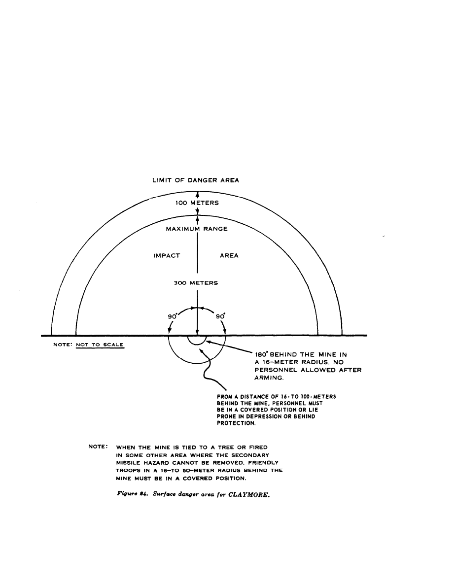
5. Danger Area
a. Danger From Fragments (fig. 4). The
danger area consists of a 180° fan with a radius
of 250 meters centered in the direction of
aim.
b. Danger Area of Backblast and Secondary
Missiles (figs. 4 and 24). Within an area of
16 meters to the rear and sides of the mine,
backblast can cause injury by concussion
(ruptured eardrums) and create a secondary
missile hazard.
(1) Friendly troops are prohibited to the
rear and sides of the mine within a
radius of 16 meters.
(2) The minimum safe operating distance
from the mine is 16 meters. At this
distance, and regardless of how the
mine is employed, the operator should
be in a foxhole, behind cover, or lying
prone in a depression. The operator
and all friendly troops within 100
meters of the mine must take cover to
prevent being injured by flying sec-
ondary objects such as sticks, stones,
and pebbles.
4
5
6
7

CHAPTER 2
MECHANICAL TRAINING
Section I. INTRODUCTION
6. General
This section describes and illustrates the
M18A1 antipersonnel mine and the electric and
nonelectric firing systems that can be used
to detonate the mine.
7. Detailed Description
a. Mine.
(1) Nomenclature --Mine, antipersonnel,
M18A1.
(2) Common name _CLAYMORE.
(3) Type -------------Antipersonnel.
(4) Weight -------------3½ pounds.
(5) Dimensions ---- 8½ inches long; 1 3/8
inches wide; 3¼
inches high (legs
folded); 6¾ inches
high (legs unfold-
ed).
(6) Firing unit
The outer surface of
construction.
the mine is a
curved,
rectangu-
l a r ,
olive-drab,
molded case of fi-
berglass-filled poly-
styrene (plastic).
In the front por-
tion of the case is
a
fragmentation
f a c e containing
steel spheres emb-
bedded in a plastic
matrix. The back
portion of the case
behind the matrix
contains a layer of
explosive.
(7) Explosive -------------1 ½ pounds of com-
position C4.
8
(8)
(9)
(l0)
Detonator wells. Two detonator wells
are located on the top of the mine
which allows for single or dual prim-
ing. These wells are sealed by the
plug ends of the shipping plug prim-
ing-adapters which prevent entry of
foreign materials into the detonator
wells. The slotted end of the shipping
plug priming-adapter is used to hold
an electric blasting cap in place when
the mine is armed. The shipping plug
priming-adapter is merely reversed
when the mine is to be armed.
Peepsight and arrows. The molded
slit-type peepsight and arrows (fig.
10) located on top of the mine are
used to aim the mine.
Legs. Two pairs of scissors-type fold-
ing legs located on the bottom of the
mine enable it to be emplaced on the
ground. The mine can also be tied
to posts, trees, etc.
b. Accessories.
(1) M57 firing device.
(a) One M57 electrical firing device is
issued with each M18A1. This de-
vice is a hand-held pulse generator.
A squeeze of the handle produces
a double (one positive, one nega-
tive) 3-volt electric pulse of suffici-
ent energy to fire the electric blast-
ing cap through the 100 feet of
firing wire which is issued with the
mine. The M57 device is 4 inches
long, approximately 1½ inches
wide, 3¼ inches high, and weighs
three-fourths of a pound. On one
end of the firing device is a rubber
connecting plug with a dust cover.
(b)
(c)
The M57 firing device is shown in
figure 5.
The safety bail on the M57 elec-
trical firing device (fig. 6) has two
positions. In the upper SAFE posi-
tion, it acts as a block between the
firing handle and the pulse genera-
tor. In the lower FIRE position, it
is clear of the firing handle and
allows the pulse generator to be
activated. The M18A1 antiperson-
nel mine with the M57 firing device
connected is shown in figure 7.
The M57 electrical firing device and
firing wire should not be discarded
after initial use. Another electric
blasting cap can be attached to the
firing wire and the M57 device can
be used to fire other devices, such as
fougasse bombs and demolition
charges, provided no more than 100
feet of firing wire and one M6
blasting cap are used.
(2) M4 electric blasting cap. The M4
electric blasting cap (fig. 7) consists
of an M6 electric blasting cap attached
to 100 feet of firing wire. Attached to
the firing wire connection is a com-
bination shorting plug and dust cover.
The shorting plug prevents accidental
functioning of the blasting cap by
static electricity; the dust cover pre-
vents dirt and moisture from enter-
(3)
ing the connector. The firing wire is
wrapped around a flat paper and then
rolled to form a package 6 inches long,
4 inches wide, and 2 inches high. A
piece of insulating tape is used to hold
the package together.
M40 test set. The M40 test set (figs.
17 and 18) is an instrument used for
checking the continuity of the initiat-
ing circuit of the mine. (For further
details on the M40 test set, see para
15.)
Note. Only one of the six bandoleers in
each packing box contains a test set. The
bandoleer containing the test set is marked
by an identification tag on the carrying
strap (fig. 2).
Bandoleer. The M7 bandoleer (fig. 2)
c. M7
is constructed of water resistant canvas (olive-
drab color) and has snap fasteners which se-
cure the flap. The bandoleer has two pockets;
one pocket contains the mine and the other con-
tains a firing device, a test set, and an electric
blasting cap assembly. A 2-inch wide web strap,
which is used as
sewn to the bag.
to the inside flap
. .
a shoulder carrying strap, is
An instruction sheet is sewn
(fig. 3).
9
161-020 0 - 94 - 2
Section II. COVERAGE AND METHODS OF FIRE
8. Fire Discipline
Since the M18A1 mine can be fired only once,
fire discipline is of paramount importance. The
mine should not be used against single person-
nel targets; rather, it should be used for its in-
tended purpose—massed personnel. When lead
elements of an enemy formation approach with-
in 20 to 30 meters of the mine, it should be
detonated. If practicable, and to insure fire
discipline, actual authority and responsibility
for target selection and timely detonation
should rest with squad leaders or their su-
periors.
9. Controlled Frontal Coverage
a. For effective coverage of the entire front
of a position, mines can be placed in a line no
closer than 5 meters and no farther apart than
45 meters. Preferred lateral and rearward sep-
aration distance is 25 meters (fig. 8).
b. If mines are placed in depth (from front
to rear), the minimum rearward separation
distance is 5 meters, provided secondary mis-
siles are removed. This distance is sufficient
to prevent possible disturbance or damage to
the rearward mines.
10. Methods of Fire
The M18A1 mine can be employed in either
the controlled or uncontrolled role.
a. Controlled Role. The mine is detonated
by the operator as the forward edge of the
enemy approaches a point within the killing
zone (20 to 30 meters) where maximum casual-
ties can be inflicted. Controlled detonation may
be accomplished by use of either an electrical
or nonelectrical firing system (fig. 9). When
mines are employed in the controlled role, they
are treated the same as individual weapons and
are reported for inclusion in the unit fire plan.
They are not reported as mines; however, the
emplacing unit must insure that the mines are
either removed, detonated, or turned over to
a relieving unit.
b. Uncontrolled Role. Uncontrolled firing is
accomplished when the mine is installed in
such a manner as to cause an unsuspecting
enemy to detonate the mine. Mines employed
in this manner must be reported and recorded
as land mines.
10
Section III. FUNCTIONING AND INSTALLATION
11. Functioning
a. Electrical Firing. When the M18A1 is
armed, actuating the M57 firing device handle
(fig. 5) with the safety bail in the FIRE posi-
tion provides sufficient electrical energy to
detonate the M6 electric blasting cap. The
detonation of the blasting cap, in turn, sets off
the high explosive charge (composition C4).
Detonation of the high explosive charge causes
fragmentation of the plastic matrix and pro-
jects spherical steel fragments outward in a
fan-shaped pattern (fig. 4). This mine is
sufficiently waterproof to function satisfactorily
after having been submerged in salt or fresh
water for 2 hours.
b. Nonelectrical Firing. The M18Al mine is
deliberately detonated by the operator pulling
or cutting a trip wire attached to a nonelectrical
firing device (fig. 9). A nonelectric blasting cap
attached to the firing device and crimped to a
length of detonating cord sets off the detonating
cord. At the other end of the detonating cord,
a second crimped nonelectric blasting cap,
which is inserted in one of the detonator wells,
detonates the mine.
12. Installation for Electrical Firing
a. Laying and Aiming.
(1)
(2)
(3)
Remove the mine and accessories (fig.
2) from the bandoleer. Read the in-
struction sheet (fig. 3) attached to
the flap of the bandoleer before pro-
ceeding with the installation of the
mine.
The M57 firing device must be in the
possession of the individual installing
the mine. This prevents accidental
firing by a second individual.
Turn the legs downward and spread
them about 45° apart. Twist both
pairs of legs so that one leg protrudes
ahead and one behind the mine, and
position the mine so that the surface
marked FRONT TOWARD ENEMY
11
(4)
12
and the arrows on top of the case
point in the direction of the enemy
or the desired area of fire. On snow
or extremely soft ground (mud), the
bandoleer may be spread beneath the
mine for support. To prevent the mine
from tipping in windy areas, or when
the legs cannot be pressed into the
ground, carefully spread the legs to
the maximum width (approximately
180°) so that the legs will be to the
front and rear of the mine. A top
view of the M18A1 antipersonnel mine
is shown in figure 10.
Select an aiming point (tree, bush,
etc.) that is approximately 150 feet
from the mine and which projects ap-
proximately 8 feet above the ground
(fig. 11).
This approximates 2½
meters at a distance of 50 meters.
Position the eye approximately 6
inches (15 cm.) away from the mine
and aim the mine by sighting through
the peepsight. The groove of the sight
should be in line with the aiming
point. The aiming point should be in
the center of the desired area of cov-
erage, and the bottom edge of the
peepsight should be parallel to the
ground that is to be covered with the
fragment spray.
b. Arming and Electrical Firing.
(1) Unscrew either the right or left
shipping plug priming-adapter, and
reverse it to allow the firing wire to
be placed into the slot provided in
the priming-adapter portion (fig. 12).
Remove the insulation tape and un-
roll the paper form from the firing
wire. Make sure that the firing wire
is uncoiled without tangling or kink-
ing. Retain the paper form and the
tape for possible future use. Hold
the blasting cap while unwinding ap-
proximately 3 meters of the firing
wire. Make certain that the combina-
tion shorting plug and dust cover are
13

(2)
(3)
(4)
(5)
14
assembled to the connector of the
firing wire before placing the blasting
cap into the detonator well. Wrap
the firing wire around a stake lo-
cated approximately 1 meter from the
mine to prevent the mine from be-
coming misalined if the firing wire
is disturbed.
A firing circuit test (para 15) should
be conducted before the blasting cap
is placed into the detonator well. This
test checks the continuity of the firing
circuit.
Slide the slotted end of the shipping
plug priming-adapter on the firing
wires of the blasting cap between the
crimped connections and the blasting
cap. Pull the excess wire through the
slotted end of the shipping plug prim-
ing-adapter until the top of the blast-
ing cap is firmly seated in the bottom
portion of the shipping plug priming-
adapter. Screw the shipping plug
priming-adapter and the blasting cap
into the detonator well.
Warning:
Make certain that the
face of the mine marked “front toward
enemy” and the arrows on top of the
mine point in the direction of the
enemy.
Recheck the aim of the mine. Camou-
flage the mine and unwind the re-
maining firing wire to the firing po-
sition. If possible, bury the firing
wire to protect it from artillery fire
and detection. The operator should
be in a foxhole, or in a covered posi-
tion at least 16 meters behind or to
the side of the emplaced mine. If
possible, perform the tests in para-
graph 15 before arming the M18A1.
If the area is subjected to mortar or
artillery bombardment, retest the cir-
cuit.
Remove the dust cover from the con-
nector on the firing device; also, re-
move the combination shorting plug
and dust cover from the end of the
firing wire. Plug in the two con-
nectors. Before connecting the firing
wire to the M57 firing device (fig. 5),
(6)
(7)
the safety bail must be in the SAFE
position. Before attaching the firing
device, insure that personnel are un-
der cover at least 250 meters away
from the front and sides of the mine
and at least 100 meters to the rear
of the mine. The firing device should
not be connected to the firing wire
until the actual time of firing.
After testing (para 15), the mine
is ready for firing. To fire the mine,
position the firing device bail in the
FIRE position.
Fire with a firm, quick squeeze of the
firing device handle.
13. Installation for Nonelectrical Firing
A nonelectric firing system utilizing a ring
main is shown in figure 13. Instructions for
laying, aiming, and arming the mine using two
nonelectric M7 blasting caps, a piece of
detonating cord approximately 25 feet long, a
pull wire, and a pull-type or pull release-type
firing device, such as the M1 or the M3 is dis-
cussed in a and b below. Instructions for lay-
ing, aiming, and arming the mine using a dual
firing system and a ring main is discussed in
c below. To arm the mine by the methods de-
scribed below, a thorough knowledge of ex-
plosives and demolition materials and the use
and installation of land mines and boobytraps
is required. Material on these subjects and
techniques is contained in FM 3-5, FM 5-25,
FM 5-31, FM 20-32, FM 31-10, TM 9-1375–
200 and TM 9-1345-200.
a. Pull Wire Initiation of the Mine (con-
trolled).
(1)
(2)
Laying and aiming the mine are per-
formed in the same manner as for
electrical firing. For details on laying
and aiming, see paragraph 12 a.
Crimp a nonelectric blasting cap to
a firing device. With the nonelectric
blasting cap attached, fasten the firing
device to the detonating cord with
tape. Using tape, wire, twine or cord,
fasten the firing device securely to a
firmly emplaced stake (fig. 13). In-
sert the detonating cord into a sec-
ond nonelectric blasting cap and
crimp the cap to the detonating cord.
Carefully insert the cap into the
(3)
detonator well. Secure the cap in the
detonator well by carefully taping or
tying the detonating cord to the mine.
A method of taping detonating cord
to a nonelectric blasting cap is shown
in figure 14.
Attach a pull wire securely to the pull
ring of the firing device. The pull
wire should be sufficiently long to
allow actuation of the firing device
from a protected position at least 16
meters to the rear of the mine. Care
must be taken during emplacement to
secure the firing device so that the
mine will not be dislodged by a pull
of the detonating cord of the trip-
wire.
b. Tripwire Initiation of the Mine (uncon-
trolled).
(1)
(2)
(3)
Laying and aiming the mine are per-
formed in the same manner as for
electrical firing. For details on lay-
ing and aiming, see paragraph 12 a.
The preliminary steps used to arm
the mine are the same as those de-
scribed in a (1) through (3) above.
The tripwire and the firing device,
which are stretched across a trail or
other avenues of approach, must be
securely attached to two stakes firmly
emplaced in the ground at a distance
of 20 to 30 meters forward of the
mine (fig. 15).
15
c. Nonelectric Method Using Dual Firing or
Ring Main.
(1) Dual firing.
(a) Obtain two 10-meter lengths of
(d)
(b)
(c)
detonating cord, four M7 nonelec-
tric blasting caps, and two pull-type
firing devices. Details for using
(e)
dual firing or ring main systems are
contained in FM 5-25.
Remove both shipping plug prim-
ing-adapters from the mine.
Crimp an M7 nonelectric blasting
the mine. While moving back to a
safe firing position, unwind the
detonating cord.
Emplace the mine and the deto-
nating cord as described in a (1)
through (3) above.
Attach a pull-type firing device and
a tripwire (or pull wire) to the
free end of each piece of deto-
nating cord (fig. 13). Use the pro-
cedures described in a or b above.
(2) Ring Main.
cap to the end of each piece of
(a)
detonating cord. Insert the caps in-
to the detonator wells, and carefully
(b)
tape or tie the detonating cord to
Follow the instructions in (1) (a)
through (d) above.
Make a ring main as described in
FM 5-25 (fig. 13).
16
(c)
(d)
When mines are emplaced one be-
hind the other, the one nearest the
enemy is generally fired first. Mines
emplaced laterally may be fired in
any order or simultaneously.
The mine and the danger area
around the mine must be visible
from the firing position so that
friendly personnel in the vicinity of
the mine may be seen.
14. Camouflage
a. Although the M18A1 is painted olive-drab
to facilitate camouflaging, it is necessary to
blend the mine into its surroundings to pre-
vent its detection.
b. Only lightweight foliage, such as leaves
and grass should be used to avoid increasing
the secondary missile hazard to the rear of
the mine.
c. Both the front and rear of the mine should
be camouflaged with foliage. The firing wire
should also be camouflaged or buried under-
ground. If used, detonating cord should not
be buried; however, it may be covered with
light foliage. For the principles and methods
of camouflage, see FM 5-20.
15. Testing
a. M40 Test Set. One M40 test set is pro-
vided with each case of six M18A1’s. The test
set is an instrument used for checking the con-
tinuity of the electrical firing circuit. A
shipping tag on the carrying strap marks the
bandoleer which contains the test set. The test
17
set is 2 inches long, 1½ inches high, and weighs
8 ounces. A small window is located on top of
the test set and is used for observing the flashes
of the indicating lamp (figs. 17 and 18). The
M18A1 antipersonnel mine set up for circuit
testing is shown in figure 16.
b. Detailed Circuit Testing Procedure. The
firing circuit test should be conducted before
the blasting cap is placed into the detonator
well. This precaution will prevent the de-
struction of the mine if the testing set mal-
functions and detonates the electric blasting
cap. If the blasting cap is detonated during
testing, it can be replaced by a standard elec-
tric blasting cap attached to the remaining
firing wire. Before and after completion of
the firing device and blasting cap continuity
tests, ascertain that the firing device safety bail
is in the SAFE position.
(1) Testing the M57 firing device and the
M40 test set.
(a) Remove the dust cover from the
connector of the firing device and
from the female connector of the
test set. Plug the test set into the
firing device (fig. 5). Leave the
combination shorting plug and dust
cover assembly on the other end
of the test set. Position the firing
device bail to the FIRE position
and actuate the handle of the firing
device with a firm, quick squeeze
and observe the flashing of the lamp
through the window of the test set.
The window of the test set should
be held near the eye when checking
the firing device and blasting cap
circuitry. This minimizes the risk
of enemy observation in the dark
and enables the operator to see the
lamp flashing, even in bright sun-
light.
(b) Flashing of the lamp indicates that
the firing device is functioning
properly. If the lamp does not flash
(on and off), it could be caused
by corrosion on the electric con-
nectors of the test set. The firer can
overcome this by connecting and
disconnecting the shorting plug dust
cover on the M40 test set. If the
test set indicates that several firing
devices are faulty, retest with an-
other set since the first one may be
defective. Side and top views of the
M40 test set are shown in figures
17 and 18.
(2) Testing the blasting cap.
(a) After determining that the firing
device and test set are operative,
remove the shorting plug dust cov-
er from the connector of the firing
wire and from the end of the test
set. Plug the connector of the firing
wire into the test set. Position the
M57 firing device bail to the FIRE
18
(b)
(c)
position. Insure that no friendly
personnel are near the blasting cap,
as it may detonate.
DETAILED CIRCUIT TESTING
IS CONDUCTED WITHOUT THE
BLASTING CAP INSERTED INTO
THE DETONATOR WELL.
When the handle of the firing de-
vice is actuated, a lamp in the win-
dow of the test set will flash. This
flash indicates that the blasting cap
circuitry is satisfactory. If there
is no flash, replace the blasting cap
and retest.
Immediately after the circuit test,
the firing device is disconnected
from the firing wire and the short-
ing plug dust cover is connected
(d)
to the firing wire. The operator re-
turns to the mine WITH THE
FIRING DEVICE IN HIS POS-
SESSION and inserts the blasting
cap into the detonator well. The
operator then rechecks the aim of
the mine and returns to his firing
position.
If an extended period of time lapses
between the circuit test and the
insertion of the blasting cap into
the detonator well, or if the area is
subjected to artillery or mortar fire,
another test should be conducted.
Note. If time available precludes the
conduct of a circuit test with the blasting
cap removed from the mine, then an ab-
breviated test may be conducted with the
blasting cap inserted into the detonator
19

well. If an abbreviated test is conducted,
all personnel must be under cover at least
250 meters away from the front and sides
of the mine and 100 meters to the rear of
the mine.
16. Disarming and Destruction
a. Disarming a Mine with an Electrical
Firing System.
(1)
(2)
(3)
(4)
(5)
Prior to disarming the mine, the firing
device safety bail must be in the
SAFE position.
Disconnect the firing wire from the
firing device. Replace the combina-
tion shorting plug dust cover on the
firing wire connector and the dust
cover on the firing device connector.
Unscrew and remove the shipping
plug priming-adapter containing the
blasting cap from the mine. Remove
the blasting cap and firing wire from
the shipping plug priming-adapter.
Reverse the shipping plug priming-
adapter, and screw the plug end of
the adapter into the detonator well.
Remove the firing wire from the stake.
Reroll the blasting cap and firing wire
and place it in its cardboard con-
tainer.
Remove the mine from its emplace-
ment. Repack the mine and its ac-
cessories into their respective pockets
in the bandoleer.
b. Disarming a Mine with a Nonelectrical
Firing System.
(1)
(2)
(3)
(4)
(5)
(6)
Prior to performing (2) through (6)
below, render the firing device safe
by replacing all safety pins.
Disconnect the pull wire or tripwire
from the nonelectric firing device.
Remove the detonating cord and blast-
ing cap from the detonator well.
Using crimpers, cut the blasting cap
free of the detonating cord. Non-
electric blasting caps and detonating
cord crimped together can be sepa-
rated only by cutting the blasting cap
free of the detonating cord.
Replace the shipping plug priming-
adapter and screw it into the deto-
nator well, plug end down.
Remove the mine from its emplaced
position and repack. Store accessory
items in appropriate containers.
c. Destruction of Mine to Prevent Enemy
Use. CLAYMORES can be most quickly de-
stroyed by detonation or burning. For proper
destruction procedures, see TM 9-1345-200.
20

CHAPTER 3
TRAINING
17. General
Training is divided into two phases—phase
I and phase II. Phase I training is designed
to familiarize the soldier with the charac-
teristics, capabilities, and installation of the
M18A1 using its electrical firing system. In
phase II training, the soldier receives further
instruction in nonelectrical firing systems,
tactical employment, and other advanced train-
ing. This training is designed to fully prepare
the soldier to employ the mine effectively in
combat.
18. Phase I Training
a. Purpose. To provide the minimum amount
of training required to employ the M18A1 with
the electrical firing system in the controlled
role, using the components found within the
M7 bandoleer.
b. Elements of Phase I Training. The soldier
receives training in the following areas:
(1)
(2)
(3)
(4)
Characteristics, mechanical training,
and capabilities of the M18A1 (para
3-l0).
Aiming, sequence of installation, cir-
cuit testing, and disarming (para 12,
15, and 16 a).
Safety procedures (app. III).
Camouflage techniques (para 14).
c. Practical Exercises. Emphasis should be
placed on practical exercises using inert or
simulated mines.
19. Phase II Training
a. Purpose. To provide the soldier with the
necessary skills and tactical knowledge to ef-
fectively employ the CLAYMORE, utilizing
both electrical and nonelectrical firing sys-
tems.
b. Elements of Phase II Training. In addi-
tion to phase I training, the soldier is further
trained in the following areas:
(1)
(2)
(3)
(4)
Controlled and uncontrolled nonelec-
tric firing systems (para 13).
Dual firing systems (para 13).
Ring main systems (para 13).
Tactical employment (ch 4).
c. Practical Exercises.
Initially, practical
exercises should be conducted in installing inert
or practice mines using pull wire and tripwire
actuation of the mine and in dual firing and
ring main systems. Inert or simulated items,
such as detonating cord, nonelectrical firing de-
vices, and caps should be substituted for live
explosives. Practical exercises should empha-
size employment of the CLAYMORE in vari-
ous tactical situations.
d. Use of Live Explosives. As the soldier
becomes more proficient in inert installation,
training progresses to the use of live explo-
sives. He is trained in firing systems and demo-
lition equipment as described in FM 5–25.
e. Proficiency. To maintain proficiency after
the completion of phase II training, the soldier
should employ inert mines during field train-
ing in both the controlled and uncontrolled
roles.
21

CHAPTER 4
TACTICAL EMPLOYMENT
20. General
The M18A1 mine is primarily a defensive
weapon. It may be employed to a limited ex-
tent in certain phases of offensive operations.
The M18A1 has the same basic capabilities as
antipersonnel mines and can be used in most
situations where other types of antipersonnel
mines are employed. In addition, the M18A1
has the capability of being sighted directionally
to provide fragmentation over a specific area
and does not necessarily rely upon chance det-
onation by the enemy. The M18A1 is adaptable
for covering the ranges between maximum hand
grenade throwing distance and the minimum
safe distance of mortar and artillery support-
ing fires.
21. Defense
a. General. The M18A1 normally is em-
ployed in the controlled role as an antiperson-
nel mine. When used in conjunction with other
types of antipersonnel and antitank mines, the
employment of the M18A1 will be governed by
the procedures described in FM 20-32.
b. Minefields.
(1)
(2)
(3)
Ease of transportation, installation,
and removal facilitates the use of the
M18A1 in protective, defensive, and
nuisance minefield.
The M18A1, with its controlled dis-
persion pattern, is designed to cover
areas where enemy personnel attacks
in force are anticipated. They may
be located singly, or in multiples (fig.
8).
CLAYMORES may be mixed with
antipersonnel and antitank mines in
conjunction with nuisance minefield
and arranged for detonation by trip-
wire.
(4)
(5)
The M18A1 can supplement other
mines within a protective minefield,
and can be installed and employed
in either the controlled or uncon-
trolled roles. The configuration and
composition of the minefield pattern
varies with the terrain and tactical
situation.
The M18A1 can be used to cover
portions of defensive minefield by
emplacing it on
the minefield
perimeter, or within the field to cover
lanes between mines. The controlled
method of employment is desirable.
Care should be taken to insure that
the mine is properly aimed to pro-
vide fragmentation effect over and
not into the minefield. This can be
accomplished by securing the mine
to trees or other elevated objects which
are at least 2 meters above ground
level.
c. Find Protective Fires. The M18A1 can
be employed to fill the dead space of the final
protective fires of automatic weapons in de-
fensive positions. Depending on the importance
of the area being protected, CLAYMORE mines
may be emplaced behind each other in relatively
close proximity. To avoid the risk of sympa-
thetic detonation, mines should be placed no
closer than 5 meters apart. Normally, mines
closest to the enemy will be detonated first. If
the enemy continues to approach a defender’s
position, he will successively detonate rearward
mines as he comes within their range. In
determining positions for emplacing CLAY-
MORE mines, consideration must be given to
the effects of backblast on friendly positions.
d. Security of Outposts. CLAYMORE mines
are easily transported and rapidly emplaced for
security of outposts. The mines can be in-
22

stalled for complete perimeter coverage of a
position. Time permitting, several rows can
be employed. The mine can also be emplaced
to assist in covering withdrawals from out-
posts.
e. Defense of Command, Combat Support,
Combat Service Support Installations, and Re-
serve Forces.
(1)
(2)
(3)
(4)
CLAYMORE mines can be utilized to
assist in the local security of com-
mand posts and support installations;
and they can be carried in vehicles
located within these areas. In addi-
tion to providing local protection for
these installations, the mines also pro-
vide protection for the vehicles.
CLAYMORE mines so
emplaced
should be employed in the electrically
controlled role as a protective measure
against inflicting casualties on friend-
ly personnel.
It is necessary to mark, record, and
report all such positions as described
in FM 20–32. The shorting plug dust
cover must be attached to the firing
wire and the firing device should not
be attached until actual firing, par-
ticularly in rear areas where friendly
personnel move about extensively.
Reserve forces in blocking positions
or assembly areas can use CLAY-
MORES to augment their local securi-
ty forces.
f. Local Security of Halted Columns. CLAY-
MORES may be carried on tanks and other
types of vehicles and emplaced for perimeter
defense of such vehicles when they are halted.
As soon as they are halted, personnel will em-
place the CLAYMORES for close-in protection
of the vehicles.
Controlled electrical firing
should be employed for simplicity, speed, and
safety.
g. Roadblocks and Obstacles.
(1) In conjunction with roadblocks,
CLAYMORES should have a clear
field of fire to cover the avenue of
approach.
Additional CLAYMORES
should be placed on the friendly side
of a roadblock. When used to cover
obstacles, the CLAYMORE should be
(2)
placed 20 to 30 meters on the friendly
side of the obstacle. This distance also
applies to barbed wire obstacles.
Controlled detonation is most desira-
ble, since the firer can best judge the
exact moment of detonation. How-
ever, uncontrolled detonation may be
employed allowing the enemy to ac-
tivate the mine when he attempts to
breach the obstacle (para 10).
h. Boobytraps. Using standard firing de-
vices, CLAYMORE mines can be employed as
boobytraps (para 13). Concealment of the
mine and a positive detonation system is es-
sential.
The mine must be emplaced and
sighted to cover the desired area. In order to
allow for the full effects of the dispersion pat-
tern of the mine, it is best to locate it away
from the boobytrap actuation device. The mine
is adaptable to many varied situations of booby-
trapping, limited only by the ingenuity of the
individual emplacing the mine. Authority to
emplace boobytraps requires approval by the
field army commander (FM 5-31).
i. Retrograde Operations.
(1)
(2)
(3)
During a delay while on position,
CLAYMORES will be employed in the
same manner as they are when em-
ployed in the defense. During move-
ment between
positions,
CLAY-
MORES will be employed in the same
manner as a withdrawal.
During a night-type
withdrawal,
which is conducted without enemy
pressure, CLAYMORES may be em-
placed for use by the detachments left
in contact, using both controlled and
uncontrolled methods of employment.
CLAYMORES may be used to assist
in covering the gaps left by the main
force. They may be used singly or
in conjunction with other mines to
mine routes of withdrawal.
If used, the rear guard can also em-
ploy M18A1’s using the uncontrolled
means of firing to assist in covering
its withdrawal to the rear. Utilization
of the M18A1 in this manner provides
added security for the detachments
left in contact, or the rear guard, and
can delay the enemy’s advance. How-
23

(4)
ever, since the M18A1 is employed in
the uncontrolled role, it must be re-
ported and recorded as a mine.
If a covering force is used during a
daylight-type withdrawal,
CLAY-
MORES can be employed by the cov-
ering force in a manner similar to
that used in any blocking position and
also employed using the same tech-
niques as used during a night-type
withdrawal.
22. Offense
a. General. The M18A1 can be employed in
certain phases of offensive combat, and pro-
visions for its use should be considered in plan-
ning offensive operations.
The mine easily
can be transported by attacking troops for de-
fense of assembly areas, to provide security
during the conduct of the attack, and for pro-
tection during the reorganization and consoli-
dation of the objective. The M18A1 also pro-
vides an economical means for establishing
effective ambushes.
b. Offensive Combat.
(1)
(2)
(3)
Preparation for the attack. When a
unit is approaching the enemy and
occupies an assembly area prior to
an attack, it is particularly vulnera-
ble to surprise enemy attacks.
CLAYMORE mines can be quickly
emplaced around the perimeter of the
assembly area to cover the unit during
its preparation for the attack.
Conduct of the attack. During the
conduct of the attack, CLAYMORES
can be employed by the flank security
forces. The ease of employment and
disarmament of the M18A1 facilitates
its use in this manner.
Reorganization and consolidation.
During the conduct of the attack,
assaulting troops may carry CLAY-
MORES for employment during re-
organization and consolidation. After
a unit has overrun an enemy position
and pursued him by fire, it must im-
mediately begin consolidation of the
objective. The prompt emplacement
of CLAYMORES will provide the
base for an immediate defense against
possible counterattack, while leaders
reorganize their units and prepare to
continue the attack. When the final
objective is captured, mines should be
immediately emplaced. The emplaced
CLAYMORES can be integrated into
the defensive plans as they are de-
veloped.
(4) Defense of supporting elements dur-
ing the attack.
(a) CLAYMORE mines can be utilized
in command posts or in the defense
of supporting units, such as mortar
and artillery batteries. Immediate-
ly after displacement, and as the
first echelon of these supporting
units moves into new positions, ade-
quate defense measures will be es-
tablished. CLAYMORES should be
emplaced initially to cover likely
avenues
of
enemy
approach;
eventually, they should be inte-
grated with the fully developed de-
fensive position. When displace-
ments occur, the mines will be dis-
armed, collected, and moved to the
next position. If the area is to be
occupied by other units, the mines
may be left in position by mutual
arrangement with the relieving unit.
(b) When CLAYMORE mines are em-
ployed in the defense of command
posts, supporting unit installations,
or reserve forces in the rear of the
battle positions, they must be well-
marked and personnel should be
familiarized with their location.
c. Ambush. CLAYMORE mines provide an
excellent, economical means for establishing
effective ambushes deep in enemy territory with
a minimum use of friendly personnel. Small
groups can easily transport a large number
of CLAYMORES; for example, one man can
carry six CLAYMORES, enough to cover a
frontage up to 300 meters. CLAYMORES may
be employed in any or all of the following
ways:
(1) Laterally along the killing zone of the
ambush, between the ambush element
and the killing zone. This method in-
flicts maximum damage on dismounted
24
troops and is particularly useful in
countering enemy immediate action
drills that include assault into the
ambush element.
(2) At the front and rear of the killing
zone (fig. 19). This method provides
enfilade fire into the killing zones,
greater economy of employment, and
is particularly useful when the route
through the killing zone is restricted
in width. It also provides a good
counter in enemy immediate action
drills that include withdrawal or
forward movement out of the killing
zone along the original route.
(3) Laterally or at the front and rear of
the killing zone, on the far side of
the killing zone from the ambush ele-
ment (fig. 19). This method of em-
ployment is particularly effective in
countering enemy immediate action
drills that include maneuver or with-
drawal out of the killing zone by mov
ing away from the ambush element.
Care must be taken to insure the am-
bush element is protected from the
fragmentation of the M18A1.
(4) Defiles. CLAYMORES are particular-
ly effective in covering areas that
might afford the enemy cover from
small-arms fire,
such as defiles.
CLAYMORES used in ambushes may
be emplaced on the ground, in trees,
or on other upright objects which
insure a clear, unobstructed, sighted
field of fire. Controlled detonation is
desirable, since this permits the firing
to be delayed until that portion of the
enemy which the commander desires
to catch in the ambush is in the killing
zone.
Mines should be carefully
camouflaged to prevent their detec-
t i o n .
25

APPENDIX I
REFERENCES
AR 320-5
AR 320-50
AR 385-63
AR 385-65
AR 700-1300-8
AR 710-1300–1
DA Pam 108-1
DA Pam 310-3
DA Pam 310–5
FM 3–5
FM 5-15
FM 5-20
FM 5-25
FM 5-31
FM 20-32
FM 21–6
FM 21-30
FM 31-10
FM 100-5
FM 101-10–2
SM 9-2-1
SM 9-4-1375-R03
SM 9-5-1345
SR 385-10
SR 755-140-1
TA 23-100
TA 23-103
TF 7-3180
TM 9-1300-206
TM 9–1345–200
TM 9-1375-200
TM 9-1900
TM 9-1910
Dictionary of United States Army Terms.
Authorized Abbreviations and Brevity Codes.
Regulations for Firing Ammunition for Training, Target Practice and
Combat.
Identification of Inert Ammunition and Ammunition Componets.
Malfunctions Involving Ammunition and Explosives.
Distribution of Ammunition for Training.
Index of Army Motion Pictures, Filmstrips, Slides, Tapes, and Phono-
Recordings.
Military Publications: Index of Doctrinal, Training, and Organizational
Publications.
Military Publications: Index of Graphic Training Aids and Devices.
Chemical, Biological, and Radiological (CBR) Operations.
Field Fortifications.
Camouflage, Basic Principles and Field Camouflage.
Explosives and Demolitions.
Use and Installation of Boobytraps.
Land Mine Warfare.
Techniques of Military Instruction.
Military Symbols.
Barriers and Denial Operations.
Field Service Regulations—Operations.
Staff Officers’ Field Manual—Organizational, Technical, and Logistical
Data—Extracts of Tables of Organization and Equipment.
Stock List of All Items, Price List.
Demolition Equipment Set, Explosive Initiating, Electric and Nonelectric.
Ammunition and Explosives, Land Mines.
Army Safety Program.
Ammunition.
Ammunition, Rockets, and Missiles for Training.
Dummy, Drill, and Inert Ammunition.
Technique of Employment, M18 and M18A1 Antipersonnel Weapons
(CLAYMORE).
Care, Handling, Preservation, and Destruction of Ammunition.
Land Mines.
Demolition Materials.
Ammunition, General.
Military Explosives.
26
APPENDIX II
M18 ANTIPERSONNEL MINE
1. General
The M18 antipersonnel mine is an earlier
model of the M18A1 antipersonnel mine, which
is described in chapters 1 and 2. The difference
between the two models may be seen by com-
paring figure 20 with figures 1 and 7. The M18
and the M18A1 are similar in use and func-
tioning. The M18 antipersonnel mine is now
limited standard.
2. Description
a. General. The M18 antipersonnel mine
comes in two versions—with or without a peep-
sight; otherwise, both versions are identical
(fig. 20). The mine is a curved, rectangular,
plastic case and contains a layer of composition
C3 explosive. It has a fragmentation face of
rectangular steel fragments. The front face
containing the steel fragments is designed to
produce a fan-shaped spray which can be aimed
at a prescribed target area. The arrow marked
on top of each mine indicates the direction of
aiming. The mine has three folding-type legs
and cloth tabs on each side of the mine. The
legs of the mine are used to emplace it above
the ground; the cloth tabs are used to tie or nail
the mine to trees or posts. There is a horizontal
cap well on each side of the mine. To reduce
detection, the mine is covered in a camouflage
pattern of green and brown fleck.
b. Detailed Description.
(1) Weight --2½ pounds.
(2) Detonator -Electric blasting cap.
(3) Explosive - ¾ pound C–3 explosive.
(4) Firing
50 feet (2–strand).
wire.
(5) Firing
Plastic frame with metal
device.
flashlight-type electric
switch.
Frame holds
two 1.5-volt BA-30 dry
batteries.
Warning: The electrical firing device issued
with the M18 CLAYMORE is not safe. Due
to its construction, it may cause premature
detonation of the mine. Whenever possible, the
battery holder (firing device) issued with the
M18 mine should be replaced by a standard
M57 firing device if the battery holder is used,
both firing wires should be connected to one
27
terminal until the desired moment of detona-
tion. Then the wires should be connected to
both terminals before the batteries are in-
serted into the battery holder (fig. 21).
3. Effects of the M 18 Mine
a. Casualty Effects (fig. 22). The M18 de-
livers a large number of highly effective steel
fragments in a fan-shaped beaten zone approx-
imately 2 meters high and 30 meters wide at a
range of 30 meters. These fragments are mod-
erately effective out to 40 meters.
b. Danger Area (fig. 22).
( 1 ) Danger from fragments. The danger
area consists of an 80° fan with a
distance of 205 meters centered in the
direction of aim of the mine.
(2) Danger from backblast and secondary
missiles to the rear and sides of the
mine.
(a)
(b)
Distance of 0 to 8 meters from the
mine. Friendly troops are prohib-
ited in this area.
Distance of 8 to 16 meters from the
mine.
Friendly troops must lie
prone or be in foxholes.
(c) Distance of 16 to 50 meters from
the mine. If all potential secondary
missiles have been removed within
a 1-meter radius to the rear and
sides of the mine, friendly troops
need only shut their eyes when the
mine is detonated.
4. Installation and Disarming
a. Arming and Laying (fig. 23).
(1)
(2)
(3)
Using the point of a 7.62-mm car-
tridge or a similar shaped object,
puncture the tape at either end of the
mine and form a hole in the explosive
for insertion of the blasting cap.
Carefully remove the special electric
blasting cap from the cardboard tube
and insert the cap into the hole of the
explosive. Insure that firm or positive
contact between the explosive charge
and the blasting cap
has been
achieved.
For emplacement above the ground,
unfold the legs of the mine and press
them firmly into the ground. The
center leg must be placed forward
28
(4)
(5)
of the mine to provide maximum
stability.
For installation on a tree or post, the
mine legs should remain folded.
Utilizing the holes in the cloth tabs of
the mine, secure it to the tree or post
by tying or nailing. For either method
of installation, the arrow on the top
of the mine must point at the center of
the fragmentation pattern.
After placement of the mine, com-
pletely unwind the 50 feet of lead
wires and run them to the firing posi-
tion. Camouflage the mine and wire.
The lead wires may be laid on top of
the ground; however, if time permits
they should be buried underground.
This will reduce the possibility of
artillery fragments dislodging the
mine and cutting the wires.
Lead
wires of M18 mines that are tactically
employed must be twisted together
and taped at two or more equidistant
places. Leads must also be shunted.
This can be accomplished by attaching
both leads to the clip on the battery
holder nearest the switch. The shunt
must then be removed by detaching
one of the leads and attaching it to the
other clip on the battery holder before
installing batteries and firing.
b. Preparation and Firing.
(1) M18 mine with M68 carrying kit.
(a)
(b)
(c)
Remove the protective wood blocks
from the battery holder.
Carefully attach the lead wires to
the clips of the battery holder. The
mine is now armed.
Insert two 1.5-volt flashlight bat-
teries (BA–30) into the battery
holder, insuring that the forward
end of each battery is facing the
clip of the holder. The switch of the
battery holder must be in the OFF
position. Batteries are not provided
with the kit. Keep batteries dry and
29
(d)
(e)
warm in cold weather. Use only
fresh or fully charged batteries.
Fire by firmly pushing the switch to
ON position.
If additional lead wire is required,
add 3 volts of power for each 50
feet (16 meters) of wire used, util-
izing additional batteries and bat-
tery holders.
(2) M18 mine with M69 carrying kit and
other firing devices.
(a) The M18 mine packed in the M69
carrying kit is designed for armor
use. The mine is fired by connecting
the lead wires to the battery of a
tank or other types of vehicles.
(b) This mine may also be fired using
pull-type firing devices, nonelectric
blasting caps, and a sufficient length
of detonating cord to bridge the
distance between the mine and the
firing devices. (See para 13, chap-
ter 3 for a detailed description.)
c. Disarming.
(1)
(2)
(3)
(4)
(5)
If dry cell batteries and battery
holder(s) are utilized, insure that the
switches are in the OFF position, and
remove lead wires from the clips of
the holder.
Short the lead wires by twisting the
bare ends together.
Carefully remove the blasting cap
from the mine.
Rewind lead wires and return the
blasting cap and wire to the cardboard
tube.
Remove the mine from its installed
position, fold the legs (if required),
and place the mine into its original
packing.
30

APPENDIX III
SAFETY
1. General
This appendix covers the safety precautions
to be observed when firing the M18A1 and M18
antipersonnel mines for training purposes.
These safety precautions will assist the in-
structor in conducting CLAYMORE training.
They are intended as a guide only and must be
used in conjunction with appropriate safety
measures prescribed in Army and/or local in-
stallation regulations.
2. Safety Precautions
a. Before firing, the officer in charge (OIC)
will check all mines to insure that—
(1) Mines are installed correctly.
(2) The fragmentation face of the mine is
pointed into the impact area and away
from friendly troops.
b. CLAYMORES will be installed only on
command of the OIC.
c. All mines will be kept under guard until
the OIC directs their issue.
d. Once a mine has been emplaced for firing
it will not be disarmed, except by order of the
OIC.
e. The firing wire will not be connected to
the firing device until ordered by the OIC.
f. When more than one mine is to be fired,
the OIC will insure that a previous firing has
not dislodged other mines in the impact area.
g. No one will enter the impact area without
the approval of the OIC.
h. After firing, the impact area will be in-
spected to insure that all mines have detonated.
3. Operational Safety Factors
a. An individual installing a mine will carry
the firing device on his person.
b. Mines must be installed in a manner that
will prevent them from becoming disoriented.
c. Blasting caps will not be inserted into the
detonator wells until the mine has been em-
placed in its firing position and aimed.
d. The safety bail on the firing device must
be in the SAFE position after the completion of
the firing circuit test.
e. The shunt will not be removed from the
firing wire of the M18 until the operator is
ready to connect it to the firing device. Before
installing batteries and firing, leads can be
shunted by attaching both leads to the clip on
the battery holder.
f. Firing wire leads of the M18 mines that
are tactically employed must be twisted to-
gether and taped at two or more equidistant
places.
4. Misfires
a. Electrical Firing System. A misfire of an
electrically employed M18A1 must be investi-
gated immediately. If the mine is dual-primed
with both electric and nonelectric caps, it will
then be necessary to wait 30 minutes before in-
vestigating the cause of the misfire.
When
handling electrical misfires, the following steps
will be taken:
(1)
(2)
(3)
Shout MISFIRE (nontactical).
Check the firing device connection to
the firing wire connector; make two
attempts to fire the mine.
Using the M40 test set, check the con-
tinuity of the electric firing circuit.
Note. Only one man at a time will investi-
gate the cause of an electric misfire.
b. Nonelectrical Firing System. If the non-
electric blasting cap initiator attached to the
detonating cord fails to function, delay investi-
gation for at least 30 minutes. Then cut the
detonating cord between the firing device and
the mine and fasten a new firing device to the
detonating cord. If the detonating cord leading
31
to the mine detonates, but the mine fails to
detonate, delay investigation until it is certain
that the mine is not burning. If the mine is not
damaged, insert a new blasting cap with det-
onating cord. In training, if the mine appears
to be damaged, it should be treated as a dud and
destroyed as instructed in TM 9-1300-206.
5. Surface Danger Area for the
CLAYMORE Antipersonnel Mine
(fig. 24)
a. When employing the antipersonnel mines,
careful consideration must be given to the
safety of friendly troops. Emphasis must be
placed on the danger areas to the rear and sides
of the mine, as well as the killing zone to the
front. Care must be exercised when installing
mines to prevent the creation of secondary
missile hazards.
b. No personnel will be allowed within 16
meters of the rear of the mine. Personnel from
16 to 100 meters in a 180° arc to the rear of the
mine will be in a covered position, lying prone
in a depression, or behind some form of
protection.
c. When a mine is installed on a tree or some
other object, the secondary missile hazard can-
not be eliminated. When mines are used in this
manner, friendly troops in a 16- to 100-meter
radius in a 180° arc must be in a covered
position.
32

APPENDIX IV
TRAINING AIDS
1. General
Training aids should be used to the maxi-
mum during phase I and phase II training. A
model, picture, or chart can be used to ex-
plain how the mine functions or is installed.
Effective training aids improve instruction and
increase understanding.
2. Training Aids
a. Training film 7–3180, "Technique of Em-
ployment, M18 and M18A1 Antipersonnel
Weapons (CLAYMORE )," 27 minutes.
b. Graphic training aid (GTA) 7–1–1,
“M18A1 Antipersonnel Mine, (CLAYMORE)”
illustrates the mine and its methods of
employment.
c. When the training film and GTA are not
available, figures 3, 10, 11, and 24 illustrate the
type of training aids that can be used to con-
duct phase I training. These training aids
should not limit the instructor’s imagination or
replace any other aids which may be available
or listed in training aids catalogs. Wherever
possible, local training aids centers should be
utilized to obtain desired training aids and de-
vices. These centers will loan and/or fabricate
the required aids and devices.
33

PIN:
023702-002
Document Outline
- FM 23-23, W/Chg 2
Wyszukiwarka
Podobne podstrony:
Mine ventilation and air (2)
Instructions for manually installing FreeSpace Open and mods (Windows)
Instructions for manually installing FreeSpace Open and mods (Mac OS X)
BSAVA Manual of Rabbit Surgery Dentistry and Imaging
4 Steyr Operation and Maintenance Manual 8th edition Feb 08
Glow Worm installation and service manual Hideaway 70CF UIS
Glow Worm installation and service manual Ultimate 50CF UIS
Glow Worm installation and service manual Ultimate 60CF UIS
Glow Worm installation and service manual Glow micron 60
Instrukcja do karabinu M16 OPERATOR MANUAL M16 AND M16A1
Model Loading and stability manual
Glow Worm installation and service manual Glow micron 40
NMS KD 0017 en V01 03 N3000 IMC and ISC User Manual
Glow Worm installation and service manual Hideaway 80BF UIS
Glow Worm installation and service manual Hideaway 50CF
Glow Worm installation and service manual Energy Saver 60 UI
więcej podobnych podstron