A-A
5
10
4
3
9
A
A
1
2
Driving axis line
Side of driving unit
Project
Original reference
Pl
ot
d
at
e:
8.
11
.2007
The information contained in this document is the sole
property of Steerprop Ltd. any reproduction or disclosure in
part or whole without written permission is prohiblited.
Drawing No.
Rev.
A1
Lang.
Eng 1/2
Sheet
New
Item code
Old
NB
Yard
Product
Mark, Size, Type
Appr.
Check.
Drawn
Date
Weight (kg)
Scale
EN ISO 13920-BF
ISO 2768-mL
General tolerance
C
B
D
E
F
G
H
J
K
L
M
A
A
B
C
D
E
F
G
H
J
K
L
6
5
4
3
2
7
8
9
10
11
12
13
14
15
1
1
15
14
13
12
11
10
9
8
7
2
3
4
5
6
16
1560
P000726
A
JYVA
2007-01-31
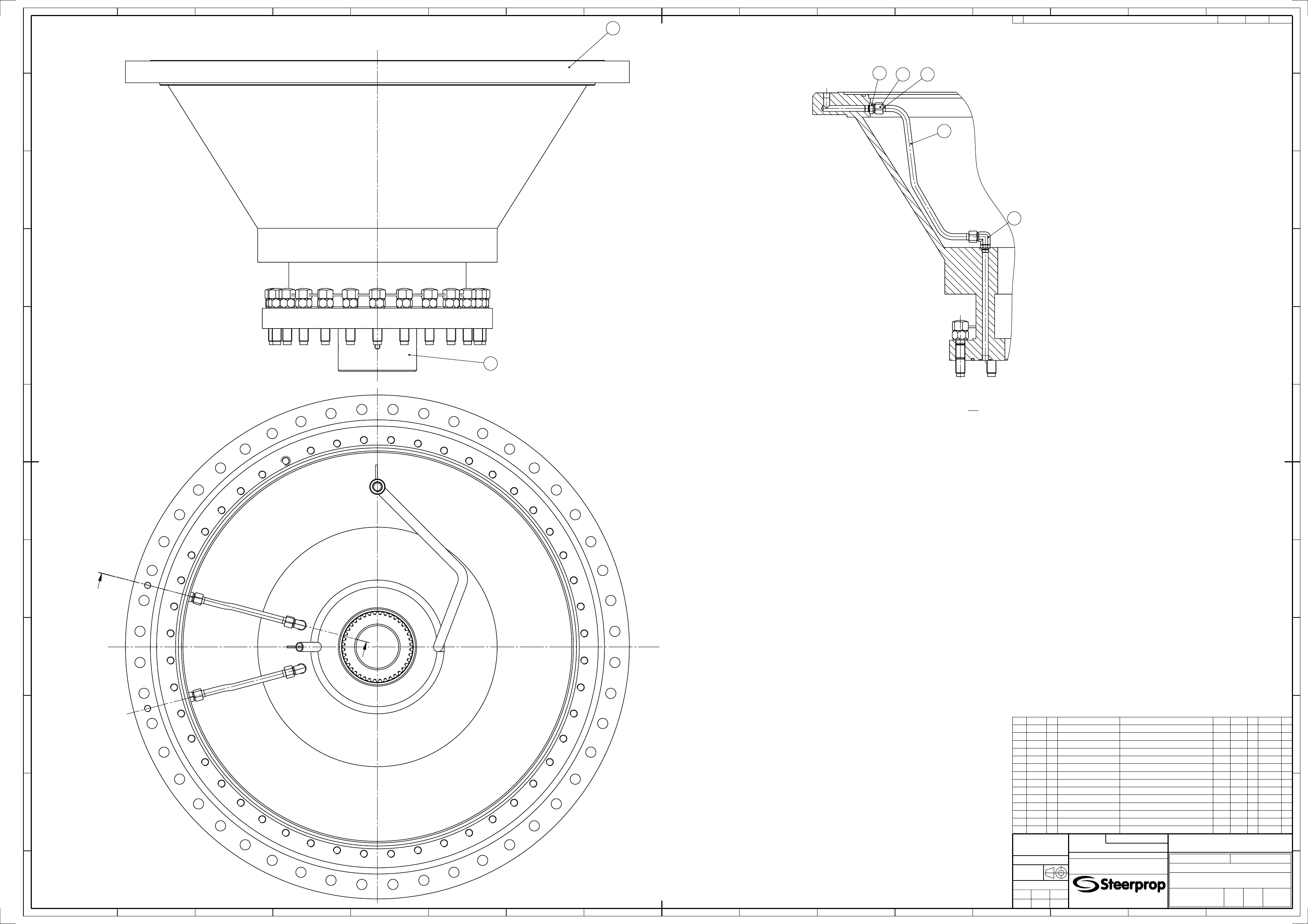
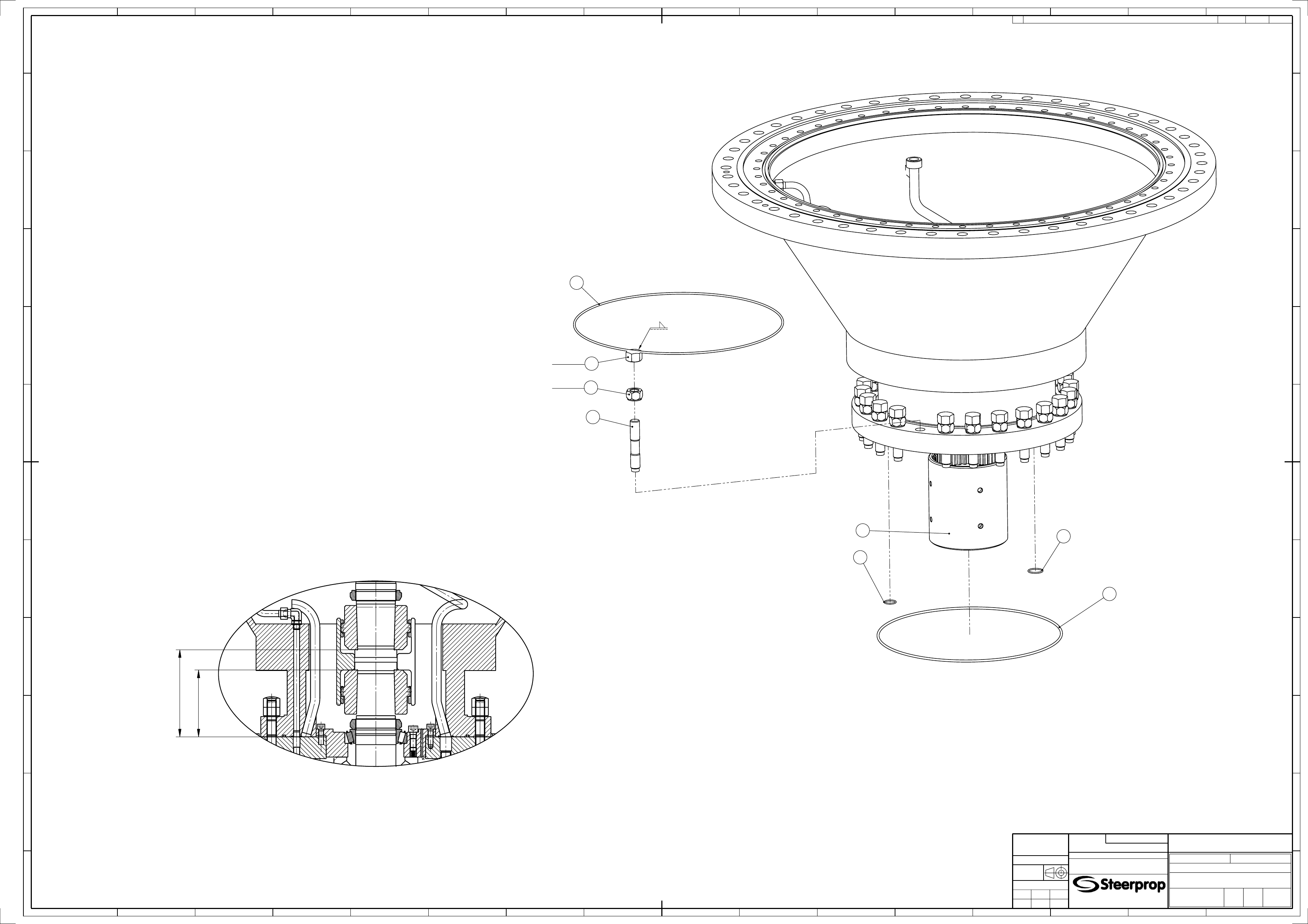
Stem tube assembly
General arrangement
SP 20
S P - A 1 V
1:5
MAMAMAMA
004116
REV
REVISION NOTE
REV DATE
CREATOR
APP
ITEM
CODE
VER DESCRIPTION
TECHNICAL DATA
DRAWING
REV
QTY
LENGTH WIDTH
1
004019 0
Stem tube
Slewing assembly
M003879 A
1
2
004060 1
Hollow shaft
HKSP20
1
3
001757 0
Nut
Parker Triple-Lok 12BMTXS
4
4
001967 0
Stud elbow
Parker Triple-Lok 12-8C4OMXS
2
5
001968 0
Stud connector
Parker Triple-Lok 12-8F42EDMXS
2
6
001076 0
Capped nut
DIN 917 - M30 - 6
24
7
002316 0
Stud bolt
M30x170
M001656 A
24
8
002343 0
Hexagon nut
DIN 2510 - M30 - NF - 8
24
9
001266 0
Hydraulic tube
Dia20x2,0 St37.4 NBK DIN 2391C/2445
2
598
10
001758 0
Sleeve
Parker Triple-Lok TXS20
4
11
001271 0
O-ring
41,82x3,53 NBR 70 Shore (Moulded ring)
1
12
001289 0
O-ring
26,58x3,53 NBR 70 Shore (Moulded ring)
2
13
002096 0
O-ring
582,68x6,99 NBR 70 Shore (Moulded ring)
1
14
001332 0
Wire
Dia6 AISI 316
1
Locking of screws according to instruction M000416.
6
8
7
11
13
12
14
100 Nm
1422 Nm
2
Connecting parts for joining lower part to stem tube.
a2
Before joining lower assembly and stem tube together check the dimension A in stem tube
and dimension B in lower assembly. Difference (A-B) must be 55...75 mm.
A
B
Project
Original reference
Pl
ot
d
at
e:
8.
11
.2007
The information contained in this document is the sole
property of Steerprop Ltd. any reproduction or disclosure in
part or whole without written permission is prohiblited.
Drawing No.
Rev.
A1
Lang.
Eng 2/2
Sheet
New
Item code
Old
NB
Yard
Product
Mark, Size, Type
Appr.
Check.
Drawn
Date
Weight (kg)
Scale
EN ISO 13920-BF
ISO 2768-mL
General tolerance
C
B
D
E
F
G
H
J
K
L
M
A
A
B
C
D
E
F
G
H
J
K
L
6
5
4
3
2
7
8
9
10
11
12
13
14
15
1
1
15
14
13
12
11
10
9
8
7
2
3
4
5
6
16
P000726
A
JYVA
2007-01-31
Stem tube assembly
General arrangement
SP 20
S P - A 1 V
1:5
MAMAMAMA
004116
REV
REVISION NOTE
REV DATE
CREATOR
APP
Wyszukiwarka
Podobne podstrony:
P000724 A Eng Lower assembly
P000720 D Eng Upper assembly
P000729 D Eng Upper assembly
P000720 C Eng Upper assembly
P000724 A Eng Lower assembly
P000722 A Eng Lower preassembly
P000718 A Eng Vertical shaft assembly
M001840 B Eng Oil tank assembly
M001809 A Eng Vertical shaft assembly
M001807 B Eng Propeller shaft assembly
M003913 A Eng Pinion shaft assembly
M001872 B Eng Propeller shaft assembly
P000722 A Eng Lower preassembly
P000718 A Eng Vertical shaft assembly
więcej podobnych podstron