e
Journal of Small Power Engineering.
Edited by Percival Marshall,
V
O L
. XLVIII. No.
A P R I L
Our Point View.
Gauge Solid Fuel Boilers.
Model Railway Men.
To
associate-1 with
steam raising in
of the g a u g e
water-tube
spirit-fired
has been
pro-
blem
for quite long
and, in fact, is likely
to remain one
for further c o n -
siderable
subject for
investigation by many model builders n-ho are
still
to that manner of making steam.
the recent controversy concerning the possi-
bilities of solid fuel
scale lncos. and the
frequent
l o c o m o t i v e
t h a t s i z e
recently been
have undoubtedly tempted a good many to
forsake
and pot boilers for
other kind.
Although
the difference
gauge 0 and
is large, the attempt to
steam
smaller gauge is being made,
hear,
in several
It will therefore be more
than cheering to these prospective builders to
know that
an gauge boiler can be success-
fully fired
solid
The perpetrator of
? - - i s
I,.
better known to most of our readers as
O n
h e
exhibited at
t h e
m e e t i n g
i s
undoubtedly the smallest solid fuel loco boiler
yet made, and successfully steamed it from all
cold in minutes.
The principal dimensions
of this job are: barrel
I
in. diameter,
I
in. long
tubes
ins.
a n d
I
i n . l o n g
i n .
i n .
long.
length of boiler and
area. ins. by in.
Heating
surface a p p r o x i m a t e l y 6
ins. chimney,
in. bore b l n s t p i p e - n o z z l e ,
in.
T h e l i t t l e g e n e r a t o r i s q u i t e
for a
double o
and is, in fact,
b e i n g
to
o f t h a t
w h i c h
could not be persuaded to perform with a pot
boiler
methylnted.
hope to hear the
result of the trials later on.
c o n s i d e r a t i o n o f
00
trials to something a trifle bigger,
though
not so spectacular,
the
enginemen and firemen’s mutual improvement
classes run by the Great Western men them-
selves.
The story of their inception and develop-
ment told in the
issue of the
magazine, though of primary concern to the
themseives, is nevertheless of con-
siderable interest to others, especially if they be,
a
i n
models.
It is
unnecessary here to labour the fact that it is
very desirable that both
and firemen
should be not only equal to but well on top of
their job-for our sake as
as their
It is even more
in their case than in
any other
can call to mind, not even except-
ing that of the marine or the aeronautical
engineer. The men of
speak have
been
of this bald truth for long enough,
even if the public has not, though undoubtedly
institution of an
e x a m i n a t i o n o f
firemen by head office running inspector
before they were put in charge of locomotives
tended to strengthen their opinion on that point.
Consequently as the need
steps
taken
to meet it, and at first some of the older men
used to
the younger ones to their homes
to instruct them. This,
found,
can well be imagined,
always satisfactory,
and
custom,
as it
gnve
place to a system
can be operated without
imposing too drastically upon the good feelings
of the elders.
These classes,
are told, consist
of enginemen, firemen and engine cleaners, and
have a properly appointed chairman, secretary
and instructors, and a code of rules. One of
the latter is that no
are allowed to speak
at one time “-the necessity for
seems to
confirm our impression that an element of keen-
ness mostly pervades the class-room.
The

The Model Engineer and
at the various
a t - e t h e u s u a l
places, but
that is not possible the
D e p a r t m e n t o f t e n a l l o w
of a
waiting-room and
a private room is
rented, the cost being
met by a small weekly
contribution by the members of the class.
officers assist the men in their
studies
by supplying models, drawings and
diagrams, and in some of the larger stations the
themselves have gone to the expense of buy-
ing their own models.
There are indeed many
other points of note in the account of these
classes, and we
glad to find the older men
have been
the credit that is undoubtedly
their due for the keen interest they have taken
in the education of their younger comrades, and
for the amount of their spare time they have
devoted to this object.
*
The
Model as International Interpreter.
some account of the difficulties experi-
enced by both instructors and students coincident
with the introduction of Mr. Churchward’s out-
side cylinder type of engine, involving piston
valves and new kind of valve gearing, the
following incident is recounted in
a mode!
saved
an
embarrassing
situation.
The
question may be asked, How does the
instructor begin with a raw candidate in
ing him the engine?
It has been found after
much experience that the best way is to start
at
outside rods and gradually
him to
locate the other parts of the gear
look-
ing at it) from the position of these rods, e.g.,
the right-hand outside rod is on the bottom
quarter.
In what position is the left-hand one?
In what position is the right big end? Which
valve is open to steam (front or back) with the
lever in the foregear? and so on.
On one
occasion a man was called to Swindon for exami-
nation from a remote branch in Wales. He
was not proficient in the English language
(Welsh being generally spoken in his district),
and the inspector knew nothing of Welsh. When
the questioning began the result can be better
imagined than described. After a considerable
amount of confusion the inspector had a
wave. He took his man to another room, con-
taining a model, and putting him to sit the
other end of the room from where the model
stood, moved the
from one position to
another, at each move pointing to the outside
rod.
The man answered every time without the
least hesitation, thus proving his study of the
engine to have been thorough.
-
-
A u s t r a l i a , v i a C a p e T o w n ,
recently, the Aberdeen liner
was
in touch
land stations in Great Britain
throughout the whole time, and was able to
65,000 woads of news, and average 738
words a day throughout the whole voyage.
Books Received.
C
R Y S T A L
R
E C E I V E R S F O R
B
R O A D C A S T
B y P e r c y W . H a r r i s . 7 5
p p . ,
crown
sewed. (Wireless Press, 1922.)
Price
I S
. 6d. net (post free
I S
.
Contents :-General principles of wireless
rectifiers and their properties
-Tuner for crystal receivers-Practical crystal
a n d
earth connections-What you may expect to
with a crystal
to adjust a crystal
detector--How to build a crystal receiver--
Index.
T
H E L
EAD
S
T O R A G E
B
A T T E R Y
.
H. G.. Brown,
c o l o u r s t a n d a r d
for acid test, 162 pp.,
cloth. (Loco-
motive Publishing Company,
Price
net (post free
Contents
:-Chemistry lead cell-Electrical
Characteristics-Formation and structure of
plates--Stationary batteries-Auxiliary appara-
tus-storage battery working-Care, treatment
and repair of cells-Battery testing-Battery
c e l l s - T h e I o n i c
Index.
AND
D
E S I G N S
,
Scale Drawings
and Working Details.
p p . ,
crown
limp. Woodworker Series.
(Evans,
Price 2s. 6d. net (post free
Contents
theatre-Doll’s houses and
furniture Crane Xylophone Windlass
Dragon-Elephant-Wagon-Rocking
Merry-go-round-Building
bricks-Gunboat-
Motor wagons-Railway station-Jointed
Windmill Cenotaph Doll’s school Doll’s
T
H E
O F A
B y
W m .
Smith,
A . C . W . A . 2 4
pp., crown
cloth.
Price 2s. 6d. net (post free 2s.
Contents
:-Routine and equipment-Loose
leaf and card systems-Stationery and corre-
spondence Filing Sales promotion Sales
orders and invoicing-Purchases and stock-The
trader’s accounts-Short-cut methods of keeping
accounts-Cost
accounting-Private
limited
companies-Index.
D
E C O R A T I O N S
A N D
R
E P A I R S
. B y W m .
Prebble.
‘ 2 2
Technical Primer Series.
Price 2s. 6d. net (post free
Contents :-Distempering
and
and enamelling-Stainmg
and varnishing-Colour washing and
distempers-Plumbing
and
water
and
hot-water
supply-Glazing,
roofing and
1 2 ,
The Model Engineer and Electrician.
Models at the Science Museum, South Kensington.
An Early Locomotive Model.
HERE was presented to the Museum some
two years ago a curious old model loco-
motive which was probably made about the
year
It was evidently made as a working
steam locomotive to run on a garden railway
with a
gauge, and, while the framing
and motion represent fairly, to a scale of
I
:
an
engine of the period, the boiler and fittings
were designed solely for working purposes and
were quite out of proportion.
As the model.
i n
About
Victor Emmanuel pre-
sented it to Mr. Solomon
who was
a railway contractor working with Mr. Thomas
Brassey, on the
of a railway he had
constructed in Italy.
It remained with his
descendants until his grand-daughter, Miss
Houghton, presented it to the
in
Fig.
I
shows the model as received
its
tender and
track on longitudinal
Working
Locomotive.
Fig. S.-The Framing and
Motion
l
one interesting form of the fork-gab valve
gear generally in
before the introduction of
Howe’s link motion in 1842, the boiler has been
removed, except the lower part of the firebos
casing, which is necessary to support the inner
framing of the engine, so that the
and
motion can be clearly seen.
The model was made by an engineer named
E. M. Clarke, of
Strand, London, presum-
ably between
and
It then. came into
the possession of Victor Emmanuel II, then
King of Sardinia and afterwards first King of
Unitrd Italy, possibly when he visited London
sleepers. The outstanding features of the boiler
are the
enormous polished brass domes, the
somewhat attenuated polished brass chimney,
and the pillar safety valve also covered with a
brass dome. The render is closely in accord
with the Stephenson tender of the time, with its
typical diamond pattern side plates, but its water
capacity has been increased by a large tank slung
under the frame between the wheels and through
which the axles pass.
Fig, 2 shows the engine framing with the
boiler removed, the only obviously non-scalar
parts remaining being the reversing lever and
The Mode! Engineer and
3%
t h e
It shows
the
construction of the
c-motion.
The
an inside-cylinder,
engine of about
t h i s
h a v i n g
P a t e n t e e of
Stephenson’s
and by the later date
accepted as
standard
to
its
and
framing resembles that
in the
Star.” built for
in
It is interesting
to
that while Daniel
a d o p t e d
of framing for all his engines,
g i v e n i t u p
o n
o f t h e
o f
t h e
cylinders of
prototype
ins.
d i a m e t e r
b y
i n s . s t r o k e ,
t h e
ins. diameter, giving a tractive
factor of
lb. of mean
in
The leading
trailing wheels
w e r e ins.
the wheelbase
10.83 ft.
The
completely
the
them.
supported by two
bolted to
outer frames. The
chests were placed on the tops of the
the
were driven; through rocking
shafts and levers. four
eccentrics
the middle of the driving
b a c k w a r d e c c e n t r i c f o r
cylinder,
ended in a
or Gab provided with tn-o spreading
forming a fork
;
of the rods faced
a n d
by links
from
ends of levers
on two trans-
verse
connected together by
a
so that,
the
w a s m o v e d , o n e
of each
into
w i t h
f r o m
e n d o f t h e
other
lifted out of gear.
The addition
of
forks to the gabs, which
made, to the
four-wccntric
probably by Messrs.
S t e p h e n s o n Co.,
e n a b l e d
engine to
the aid of
o f v i b r a t i n g h a n d
on
a s
required in the earlier gab gears
The
forks
on
the
engage the
pins,
the
of the latter. and forced
into the’
position by their
action. In
mid
of the reversing
lever both eccentrics
disconnected from the
valves
and no
expansion could he
outer frames
of wood,
on
I s a
l e c t u r e ,
J.
o f t h e
o u t t h e d i f f i c u l t y o f
making a
as to
cheapest method
of mass production of a
part.
an illustration, he
specimens of
hubs made (
I
) from solid bar, from drop
forging, (3) ‘from a malleable iron casting,
an upsetting process, and pressing
T h e
of
c o m p o n e n t
both sides
iron plates, which
formed
in one piece
the
and their
could be
single
on capstan
lathes, or on full automatics, and there
These
trussed mith round iron
rods and tied
the buffer beams and
thus
different
c o m p l e t i n g
by the boiler supports.
manufacture,
The
w h e e l
each offering its special
spring
placed above the frames
those
to the particular equipment,,
available to
manufacturer..
of
a n d
p l a c e d
the frames and
horn plates.
In addition to the outside frames, there
four inner
wrought-iron frames
extending from the back of the cylinders to the
front of the firebos to
secured
bolted
at
Each of these
frames
pair of guide bars for the
the
b e i n g f o r g e d
t h e
frames
the
bolted on
also
the valve
countershafts. Each
frame
an additional crankshaft bear-
ing,
brasses having horizontal adjustment
and being fitted between adjustable
horn
by
they could be accurately
t o
but no springs
fitted to them, so
that
c a r r i e d
vertical
but only
sustained par-t of the horizontal thrust of the
connecting-rods. This six-bearing
for
crankshaft
introduced in Stephen-
son’s Planet of 1830, being, no doubt,
or
the small diameter
it continued in use for
many years.
The wheels of
model
of cast-iron, but
those of the
probably
iron
a
number of spokes.
The
are of circular section and
ends secured
and
The
right-
for length,
the eccentric
rods
are
where they
n c c t
T h e
l e n g t h o f
the main frames
ft. and the
7 ft.
In the model
and exhaust
have been
the
tee
in the photograph has been provided for con-
necting it with the Museum cony-essed-ail
its
by +-in. cylinder-s the
model,
by steam, must have been
The illustrations
from the official
The Model Engineer
April
A
Design for a Model Compound Condensing
Steam Engine-VI.
A X L E . ”
from page 346.)
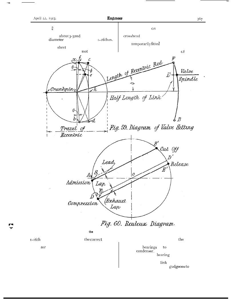
The valves can now set
to their proper posi-
tions on the valve spindle.
It will be observed
t h a t
is
in line w i t h t h e
eccentric-rod
in full gear. The (travel of the
valve is thus considerably less than the travel of
the eccentric. The motion of the valve
be the
as that due ta linking up when direct gear
is
The movement of the valve can be
determined graphically in he
following manner.
In Fig. let
and o.b. = radius of eccen-
tric and 0 the angle of advance.
Set back from
and o.b. a n g l e in the
direction of rotation, making
D . O . S .
Then D is
position of the
crank when the valve is in mid position. Draw
to
and at a distance
from it equal to the lap.
Similarly draw
at a
from it equal to the
exhaust lap.
Then S is the point of admission,
is point of cut-off, E is point of com-
pression and is point of release.
The per-
p e n d i c u l a r f r o m A
= steam lead.
From these diagrams it will easy for the
builder to find the setting of the eccentrics and
laps required for various
of cut off.
diagrams should be drawn, say, four times
full size.
Pipe
Exhaust and L.P. Steam Chest.
length of link
length of eccentric-rod
d r a w
and
at
angles to
a n d
o.b. Join c.d. and bisect at k.
Draw an arc of a circle passing through
Divide the arc
such
that
as
F.E.
(E is the
position
of the link block
in full gear.)
Then
is the half travel of valve and
is the
angle of advance.
d i a g r a m , F i g .
c a n
b e
drawn as follows :-Draw a circle with radius
=
diameter
making angle
The dimensions of the valves given in Figs.
and should give
the correct
laps, and
the eccentrics
in Fig. 25 the lead
be about
in. for both valves full
gear. It should be noticed that the construction
shown in Fig. only holds good for open rods.
If the rods are crossed angle should be set
back in the opposite
from
and
Having set the valves to the correct lead, the
crank should be rotated and the positions of
pistons measured from the tops of their stroke
off, and if the valves require lifting or
lowering a little then the adjustment can be made
altering the thickness of
washer under
the valves.
In full gear
steam should be cut
The Model
and Electrician.
off at about in. of the stroke. The pumps can
now be assembled. The air pump valves should
be made of fibre
in. thick and large
enough in
to overlap at least
all round the holes in the valve seats.
As an
experiment thin
brass valves could be tried.
The lift of the valves should
be more than
After jointing the various pump covers the
pump rods can be connected up to the pump
after slipping on the glands.
The
pump levers should be placed in their bearings
and
in position. After setting
the levers symmetrically about the centre line cf
the L.P. engine, with the centre the bearing
Diagrams showing
Method of Setting Out the Valves in their Correct Positions.
in., but the finding of
lift is
probably a matter of trial.
The
pump piston should be packed with as
many turns of cotton string as it will hold. It
should be wound on evenly and the ends tucked
under the adjoining turns. The packing should
be greased and should make the piston a good
tight fit into the barrel.
the correct distance back from
centre of the
piston rod, the holes can be mar-lied through the
feet of the
on the rectangular bosses
on the
The bosses should be drilled
and tapped and the
screwed into position.
The pumps can now be connected up to the
engine. Each pump
bearing should first be
tried on to their respective
obtain the
368
The Model
and Electrician.
correct
fit. The pump covers
connecting up the pumps for the
f i r s t t i m e , s o
of
p u m p
be observed.
p u m p c r o s s h e a d
guide should bc drilled and tapped
m a r k -
ing off in position, and bolted to the back of
pump
bearing.
I
n o w
b r i e f l y d e s c r i b e t h e
lagging, drains, etc.,
required to complete
model.
T h e
pipe connecting the H.P.
e x h a u s t
a n d L . P . s t e a m - c h e s t i s
i n
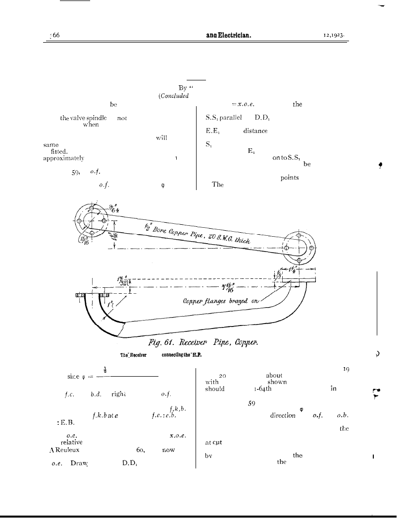
The Exhaust Pipe from the L.P. Cylinder to the Condenser.
Fig. 61.
bending the pipe, it should be cut
t o l e n g t h a n d f l a n g e s c u t f r o m s h e e t c o p p e r ,
b r a z e d , o r s i l v e r s o l d e r e d o n .
T h e
s h o u l d
drilled to suit the studs on the cylin-
ders, and after filing up the faces of the flanges
bc jointed
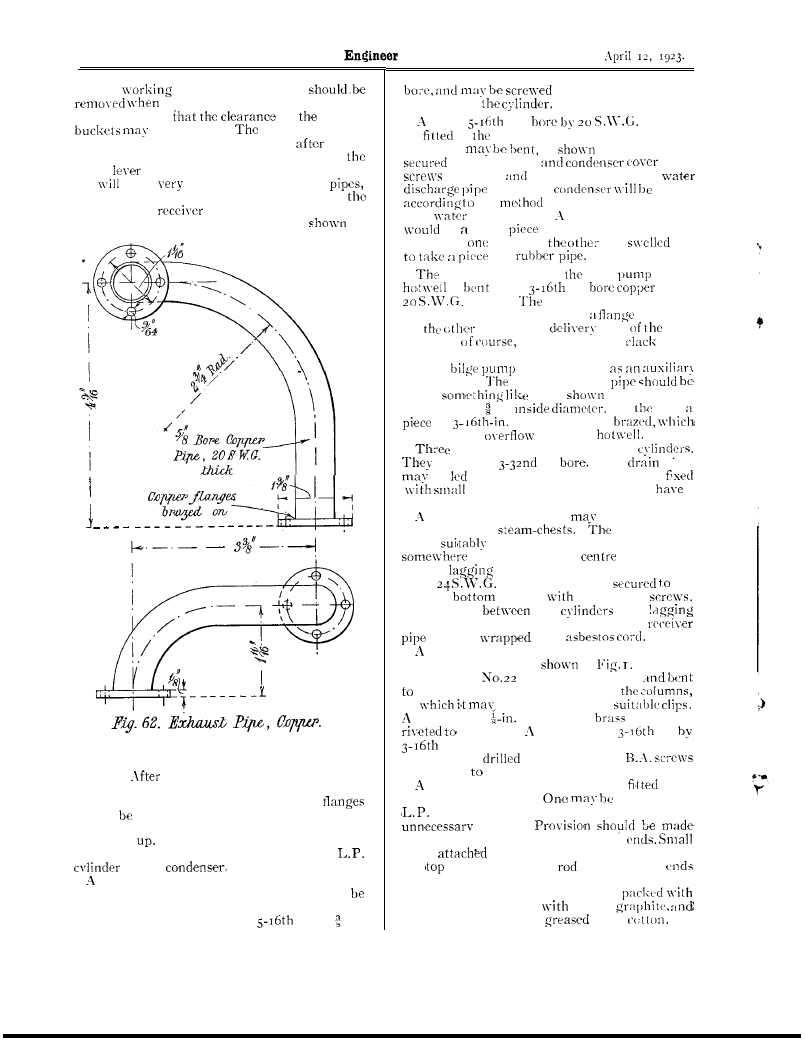
Fig. 62 shows the exhaust pipe from the
to the
steam stop valve will be required for the
H.P. cylinder.
T h i s v a l v e w o u l d p r o b a b l y
purchased from a firm specialising in fittings for
models.
It should be about
in. or in.
d i r e c t i n t o t h e b u s s
provided on
p i p e
i n .
s h o u l d
be
to
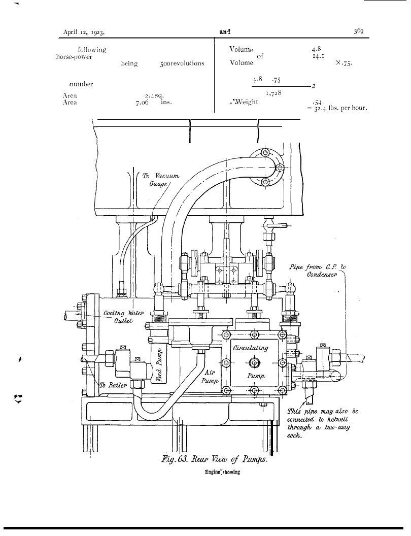
c o n d e n s e r f r o m t h e c i r c u l a t i n g
p u m p .
It
as
in Fig. 63,
a n d
t o t h e p u m p
w i t h
o r s t u d s
n u t s .
The cooling
f r o m t h e
m a d e
the
of disposing of the coo-
i n g
d i s c h a r g e .
s u i t a b l e c o n n e c t i o n
bc short
of pipe n-ith the flange
brazed on
end, and
end
out
o f
p u m p c o n n e c t i n g
feed
to the
is
from
in.
p i p e ,
t h i c k .
pipe is fitted n-ith nipple
and union nut at one end and
is brazed
o n
e n d .
T h e
side
f e e d
pump is,
connected to the
v a l v e
on the boiler.
T h e
c a n b e u s e d
feed pump.
a i r d i s c h a r g e
b e n t
t h a t
i n F i g .
I
. I t
s h o u l d b e a in.
On
side
of
c o p p e r p i p e i s
serves as an
from the
drain pipes are required for the
should be
in.
The
pipes
be
d o w n t h e f r o n t c o l u m n s a n d
c l i p s . T h e c o n d e n s e r s h o u l d
a
small vacuum gauge connected to it.
s t e a m p r e s s u r e g a u g e
be fitted to the
H . P . a n d L . P .
three gauges
could
be fitted at the front of the engine
near the top of the
column.
T h e
for the cylinders should he cut
f r o m
sheet steel, and is
the
top and
flanges
No. 8 B.A.
T h e s p a c e
t h e
a n d
should be filled with asbestos pulp. The
may be
with
guard should be fitted round the bottom of
the front columns, as
in
It should
be cut from
S.W.G. sheet steel
fit up as closely as possible to
to
b e a t t a c h e d w i t h
b e a d i n g o f
h a l f - r o u n d
s h o u l d b e
the edge. b r a s s a n g l e
in.
in. should be riveted to the bottom of the
g u a r d a n d
f o r t h e N o . 8
securing it
the bedplate.
double cock lubricator should be
to the
H . P . c y l i n d e r c o v e r .
fitted to the
c y l i n d e r c o v e r , b u t i t i s p e r h a p s a n
fitting.
for lubricating the top and bottom
pipes
to a small oil cup can be led from
the
of the connecting
to the bottom
in the usual manner.
T h e ’ c y l i n d e r g l a n d s c a n b e
asbestos cord smeared
oil and
the pump glands with
lamp
The Model Engineer
Electrician.
The
is a rough calculation of the
of H.P. cylinder =
cub. ins.
expected from the engine, assuming
Volume L.P. cylinder =
cub. ins.
that it is capable of
run at
of steam at cut off =
4.8
per minute. (It is doubtful to assume that the
Volume of steam used per minute =
air and circulating pumps will work efficiently at
this
of revolutions per minute.)
X
X
1,000
cub.
f e e t .
of H.P. cylinder =
ins.
of L.l’. cylinder =
sq.
Neglecting clearance and area of piston rod
of steam used =
lbs. per min.
,
Part Elevation of Steam
Rear of Pumps.
The Model Engineer and Electrician.
Assuming that the steam consumption for a
small
per horse-power hour,
then expected h.p. =
or assuming the total expansion to take place in
the L.P. cylinder, and a mean effective pressure
of lbs.,
7.06 x x 166
then
=
=
Cooling surface of condenser =
x 6.37 x 83
= 2.8 sq. feet.
‘44
The cooling surface is
too small for
f u l l
but should be fairly efficient,
especially if the flow of
cooling water is
by connecting
inlet side of the
circulating pump to a good head of water, such
as a water main.
As a guide in designing a suitable boiler for
the engine, the
figures will
be found useful.
I
s q f t . o f h e a t i n g s u r f a c e w i l l
4 lbs. of water per hour, the heating
surface required =
H S
= 8.1 sq. ft., with a ratio
IO
,
4
GA
grate area required =
feet.
In conclusion, I should like to add a word of
advice. Intending builders should not attempt to
build the model without first laying cut the
general arrangment for (themselves, because in
preparing an article such as this, requiring so
many more or less fully
sketches,
discrepancies in measurements are liable to
creep in, so that as a check upon the drawings
which have been given here, is perhaps
e s s e n t i a l t h a t t h e p a r t s
be first
together on paper. Many of the parts may have
been described somewhat too briefly, but I should
be delighted to give, with
permission of the
Editor, any further information about the model
to any reader who is interested. Also, I should
be pleased to hear, through the Editor, from
anyone completing it.
E. B. (Hunsletj. --We are unable to give you
particulars and details for making a
I
h.p. alter-
native current induction motor and doubt if
you would be able to obtain the
necessary for construction of the
and rotor.
These machines require very careful workman-
ship as the clearance
and rotor
must be extremely small.
do not know of
any firm supplying designs and sets of parts for
making induction motors.
Workshop Topics.
The
under
relate to
and other matters dealt
T
HE
M
ODEL
E
NGINEER
at
Street, London, E.C.4.
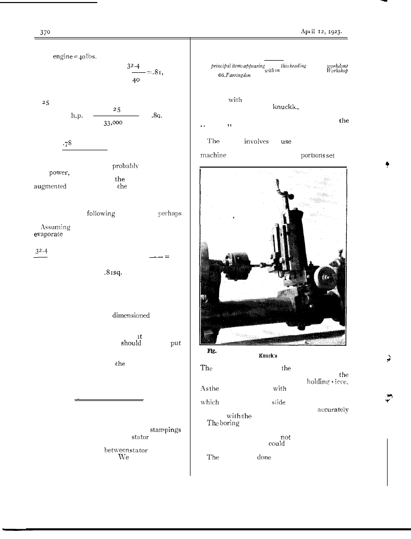
The Setting for Slot-Milling a Model
Connecting-Rod End.
Fig.
I
,
this note, shows a method of
accurately slotting the
or forked small
end, of a connecting-rod. The rod is of the
short
marine type,
a s s u p p l i e d w i t h
Stuart vertical engine parts, and is of cast
brass.
setting
the
of the “Wheeler”
milling attachment, the vertical slide, table and
vice of which are the
up.
I.-Setting a Model Connecting-Rod for Slot Milling the
End.
vice is aligned with
table accurately,
and the rod set deeply in the jaws, using
fixed half of the big end as the
jaws are square
the table, they are,
therefore, parallel with the boring table, upon
the vertical
is mounted.
This
ensures the slot milling coming out
parallel
big end.
table had to be (tilted a little to
bring the job opposite the lathe centre, allowing
for cross traverse, but
in the matter of
height, because this
be adjusted bv the
vertical slide.
slotting is
by means of a correct
size end mill, duly ciearanced upon
its
side
cutting edges and mounted in a chuck.
The
1 2 ,
The Model Engineer and Electrician.
made from the solid in a series of cuts,
feeding per cut by the lead screw, and traversing
across by the cross feed of lathe. When the
slot was complete to
depth the job was
traversed up, and the
of fork milled by
series of cross cuts, thus machining the under-
side
face.
By depressing
vertical
slide the top face was similarly done.
These
The Flexible Shaft in the Workshop.
last
involved the use of the
meter on vertical-slide feed screw, by means of
it
possible to ensure equal thickness
of the knuckle arms.
This is
a simple job, but must be carried
out with all slides well gibbed up, and the result
is more quickly and accurately arrived at than
be effected by filing.
useful article in an engineer’s work-
shop is a flexible shaft
do not think
that many model
appreciate just how
useful such a shaft can be.
It can be used
to drive grinding
drilling spindles,
Diagram showing Construction of a
Flexible Shaft.
polishing mops, etc., with
advantage that
the tools instead of being fixtures, can be
to the work and moved over its surface.
an instance of what it
do, supposing some
drill it is a much easier job, and by drilling a
small hole first and gradually increasing the size
of the drills used it is quite possible, as I have
found to my
to drill Q-in.
diameter holes in cast-iron
thick without
any great exertion. And if the drilling appara-
tus is fitted with a self-contained feed screw,
and the drill suitably packed up or cramped to
the work, there is no exertion required at all,
and holes can be drilled or counter-bored as
easily
they could be done in a drilling
machine.
Unfortunately,
s h a f t s a r e r a t h e r
expensive things to buy, when they are
up completely ready for use but there is no
necessity to go to this
for any model
engineer,
ability and who possesses.
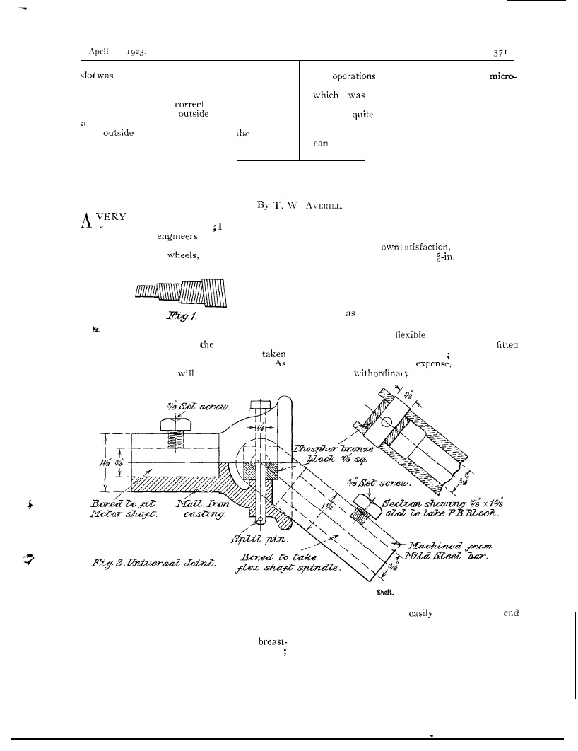
Half
Sectional Elevation of Universal Joint for Flexible
holes are required
LO
be drilled in a casting
which is much too large to be got on the
drilling machine or in the lathe. This usually
means getting out the breast-drill, and
drilling always means exceedingly hard work
but if you possess a flexible shaft to drive the
a lathe, c a n q u i t e
make up the
fittings required for such a shaft, and then the
only outlay required would be for the length
of flexible shafting and the corresponding length
of flexible casing for the shaft to run in. My
own shaft is a fairly powerful ‘one, the outside
37’
The Model Engineer and
A p r i l
casing is about in. diameter
and the
to get
appreciable power through
shaft is
in. I purchased my shaft and
a
shaft, the only thing to do is to run
casing from
H T e r r y S o n s , t h e
fast and gear
for
at
business
spring specialists, and
of their factories is
e n d . M y o w n s h a f t r u n s
it
situated in
This sounds very much
is feet long and being fitted up in a fairly
free
for Messrs. Terry and
central
in the workshop has a wide
Sons, hut I expect
unless I state where this
of action.
I originally fitted up this
shafting can be
I
be
to
to drive g r i n d i n g
on my
lot of
enquiries later on.
to
the trouble of fitting overhead
shaft is,
o f
T e r r y ’ s
the
shaft being driven and
spring shafts.
consists of several
trolled by separate countershaft.
i n
steel springs
on the top of
the grinding
spindle is coupled direct
each other,
coil
in
to the flexible shaft and runs at the same speed,
direction to the
it is wound on (see Fig.
I
) .
the n-heel
used is about 6 ins. diameter
The springs
thoroughly
together
and the shaft
plenty of power to drive it
soft
for about to ins
good cut on.
he shaft can also be used
shafts
f i x e d i n t o
of
e n d f i t t i n g s b y
h e r e o f c o u r s e t h e
must be
reduced and the most
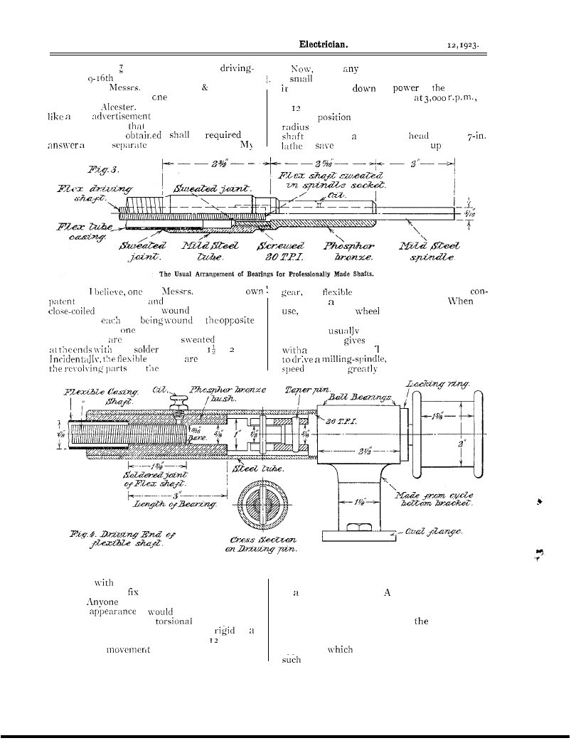
Sectional Elevation of Driving End of Shaft.
sn-eating
solder,
this being the only
convenient method of doing this is hy means
possible way to them as they cannot be
of worm and wheel. method of arranging
drilled.
examining one of these shafts
this will be mentioned later. The professionally
a t f i r s t
naturally expect
built-up shafts are usually made with plain
there would be a lot of
spring in the
spindle ends projecting from
end bearings
drive, but in practice i! is almost as
as
of the. casing fittings, so that they can be
solid bar, and in a length of shaft ft. long
clamped into any convenient piece of revolving
the slightest
at one end is instantly
apparatus
is running at the correct speed,
transmitted to the other.
as a lathe chuck, drilling-machine, or
April
The Model Engineer and Electrician.
electric
When
shafts arc driven
direct
motor, inste of coupling
greater radius of action to
shaft
the shaft
the
but it
the end bearings of the shaft
j o i n t o f
in
2 is
of some of the side
of the
of the
shaft a n d
t h e
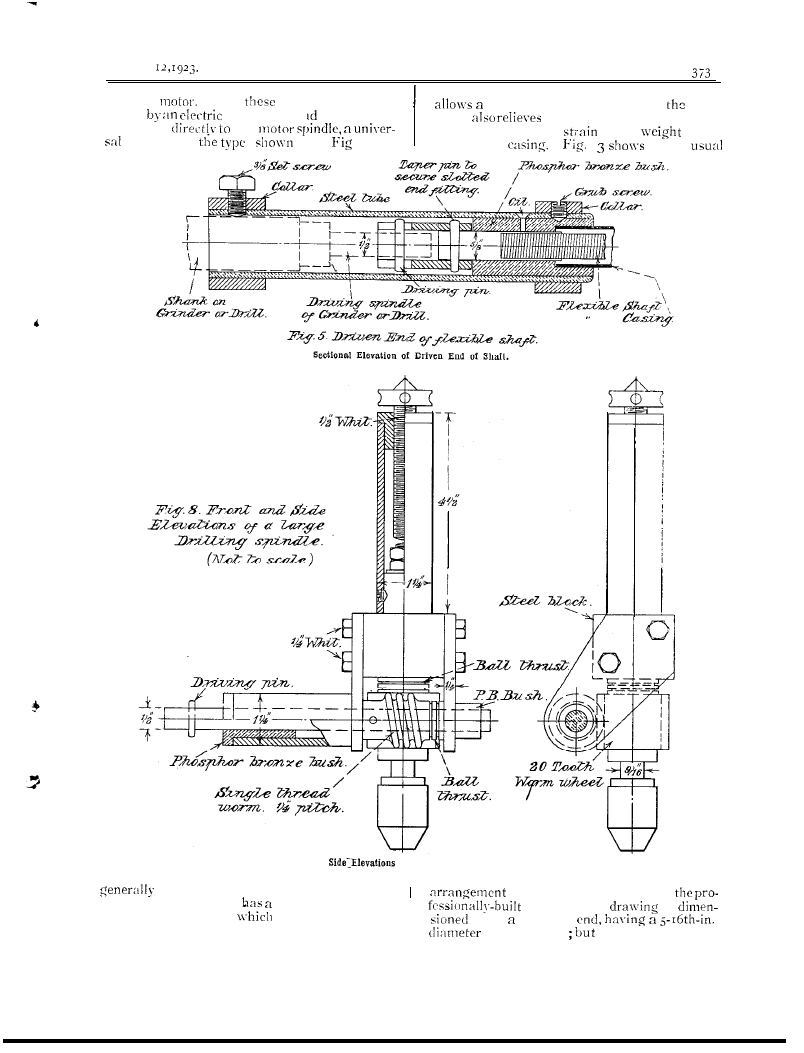
Front and
of a Large
Drilling
Spindle.
fitted. The end of the universal fitted
t o t h e m o t o r - s h a f t
b e l l m o u t h w h i c h
of the end bearings of
l i m i t s t h e a n g l e a t
t h e j o i n t c a n w o r k
shafts. The
is
and so prevents it locking.
This joint not only
f o r s h a f t
plain spindle
of course these end
374
The Model Engineer and Electrician.
according to the size of the shaft.
these
for Messrs. Terry
with spindles varying from
in. up to
I
in.
in diameter.
But this difference should be
Sectional Elevation of
Wheel Spindle.
n o t e d ,
in the
s h a f t s i z e t h e
flexible shaft to drive it is also
in.
diameter, but to drive the r-in. spindle the
flexible shaft is
18
ins. diameter. The
shown in Fig. is quite suit-
able for most purposes, but it
has bad fault in that there
is considerable side pressure
on the shaft bearings owing to
them having to carry a good
of the weight of the shaft
and casing this accounts for
the length of the bearings em-
ployed, and Messrs. Terry use
nothing else but the best
quality phosphor-bronze for
these bearings, as no other
bearing metal will stand up
to the work for long. low
speeds this side pressure is
not very detrimental to the
running of
shaft, but
found that at high speeds it
quite another matter.
at first fitted up my shaft with
ends similar in pattern to
Fig. 3, to drive my grinding
wheel, but on putting it to
work, owing to the high speed
it
r u n n i n g t h e e n d
bearings were very soon, in
spite of copious lubrication,
nearly
red hot.
I c o u l d
Elevation of a Light
Spindle with Bevel Gear Drive.
see
that
of my planing machine and when
S O
. .
stopped. After some few experiments finally
made the shaft ends as shown in Figs. and
Fig. 4 showing the driving end and Fig. the
driven. This
perfectly, as
the weight of the casing is entirely removed
from the bearings and get floating drive to
and from the shaft ends
relieves the
bearings of all strain. With the present arrange-
ment I have had the grinding wheel running for
four hours at a stretch with only a few very
short
and the bearings did not give
trouble
overheating. it may be of
interest give drawings of
grinding wheel
spindle, Fig. 6, and also two drilling spindles.
Fig. is for light drilling and is driven by bevel
gears and has two speeds, one equal to shaft
(this is useful for polishing bobs) and
the other geared down 4 to
I
.
It is fitted
chuck, holding from to in.
Fig. is for
heavier
it is geared down to
I
by
and wheel, it is fitted
ball thrusts and the
chuck holds up to in. It mill
drive a
$-in. drill if a small pilot hole is
first.
This spindle is fitted
a self-contained
feed and must be either cramped to the
work or
up to it, as a fulcrum to
the pressure of the feed if needed.
Another use
put my shaft-driven grinder to is for surface
grinding. mount the grinding head on the
i
arrangement
would not do, as found
fitted,. it transforms the planer
a very
that must have some means of supporting the
useful surface grinding machine, and I
xx-eight of the shaft and casing, as when the
rather astonished at
accurate work that this
casing was supported by hand the overheating
will turn out.
have ground up
The Model Engineer and Electrician.
375
PART
SHOWING ARRANGEMENT FOR DRIVING A MILLING SPINDLE.
The Model Engineer and Electrician.
A p r i l
s t r i p s i n s . l o n g
i n . t h i c k t h a t
did not
more than a quarter-of-n-thousandth
of an inch-in any
of their length.
Figs.
0.
a r r a n g e m e n t f o r
a milling
The flexible shaft is geared
d o n - n
single thread
of in. pitch to
of
to I,
instead of driving direct
on to the
spindle it drives short gun-
f o r m s p a r t o f t h e
on one end of this bush lathe change
a b o u t i n . w i d e
a n d
T h e
on this bush
into
f i t t e d o n
of
m i l l i n g s p i n d l e T h e
s p i n d l e
the
is adjust-
a b l e
s l o t i n t h e c a r r y i n g a r m
o n
s p i g o t o f o n e o f t h e
m i l l i n g
t h i s s l o t
o f
s e v e r a l
of change wheels so that
b e o b t a i n e d t o s u i t
cutter that is being used.
be
f r o m F i g . that
m i l l i n g
s p i n d l e i n s t e a d o f
n o s e , i s
. bored out to
taper, it is also drilled
r i g h t t h r o u g h
l o n g
d i a m e t e r
bolt is fitted
into the tang of the
is in use, thus
t h e
l o o s e
t o t h e
of the cutter
find
this
it is
to mount the cutters
to
t h e m t o r u n t r u e , a s n i t h c h u c k s
mounted on a
nose, unless the fittings
the cutters are actually turned up in
o n t h e m i l l i n g s p i n d l e ( w h i c h i s n o t
t o d o ) t h e c u t t e r s
r u n q u i t e
a d v a n t a g e o f b e i n g
able to
speed of milling
is that
if
it
b e geared
a
u p
t o
In conclusion, m i g h t
m e n t i o n
t h e g r i n d i n g h e a d , d r i l l i n g a n d
milling spindles,
been described, are
not commercial articles, but are my own design
and they have been all built up from
o d d s
e n d s , m o s t o f w h i c h
o b t a i n e d
f r o m
scrap pile, scarcely
n e w m a t e r i a l
in
of
u s e d .
Telephone Connections.
n o w
i n t h e
telephone
and since it is necessary
to
for immediate and direct
o f e a c h o n e o f t h e s e
o t h e r
in
m a y b e
f o r
hour of the
or night, it
b e
t h a t
p r o b l e m o f
an
i s n o l i g h t o n e . T o
f r o m b r e a k s , a l l p o s s i b l e c o n -
nections in
circuits
soldered
a n d i n
alone this
of
s o l d e r e d
A Motor Attachment for a
Mowing Machine.
T
H O S E
h a r e h a d t h e d o u b t f u l
o f
k e e p i n g
expanse of grass cut
a
h a n d
m a c h i n e
w i t h o u t d o u b t ,
a p p r e c i a t e
advantage of motor to do the
d o n k e y
U n f o r t u n a t e l y , t h e f i r s t c o s t i s
often prohibitive,
it was in the author’s case.
it happened,
an old
G r e e n ’ s
m a c h i n e b e c a m e a v a i l a b l e
a very
moderate figure.
This, and an old
motor
b i c y c l e
t h e w r i t e r h a p p e n e d t o
o f
machine.
Mowing
of old design,
i n c o m p l e t e i n
its parts, the main portions of
to be in
It
of the usual
d e s i g n e d t o
by a pony, the
h a n d l e s f r o m b e h i n d .
F i g .
I
of the
a r r a n g e m e n t
o f
machine.
c u t t i n g c y l i n d e r , ( R )
chain, cylinder to rollers,
c r o s s b a r s ,
c l u t c h , ( G )
lever, (H) flywheel, (I) clutch shaft, (J)
l u b r i c a t o r s ,
f o r
c l u t c h e s ,
p e t r o l
o i l
pressure pump.
The rollers,
in
all
machines, arc in tn-0 halves to facili-
tate
connecting each roller to the
which supports them is s p r i n g - o p e r a t e d
toothed-clutch,
to
e i t h e r r o l l e r
t o
g o i n g r o u n d c o r n e r .
Both
c l u t c h e s
be
b y m e a n s o f
handle.
n-ill be
later these clutches
introduced a complication
question of
drive
the motor
to be considered.
O n
e n d o f
r o l l e r s h a f t i s f i t t e d
s p r o c k e t
c h a i n s
d r i v e
s m a l l s p r o c k e t s o n t h e c u t t e r
T h i s
cylinder
t h e
k n i f e a r e t h e v i t a l
f e a t u r e s i n
m a c h i n e , a n d a p r o s p e c t i v e
p u r c h a s e r
be
advised to look
these parts before
up his mind to buy
machine.
d a m a g e d o r b a d l y
a d j u s t e d k n i f e o r
no
c a n b e
expected to cut grass.
In this case the cylinder
and slightly bent at each end,
b e a r i n g b r a s s e s
m i s s i n g a n d t h e
b e a r i n g s w e r e o f o l d d e s i g n in addition the
l o \ \ - e r k n i f e
b a d l y
T h e s e d e f e c t s
accepted
it
that they could
o v e r c o m e ,
i f n e c e s s a r y n e w p a r t s
obtained.
The Engine.
Since it
last
on motor bicycle the
e n g i n e h a d b e e n
for
a d y n a m o .
spite of hard
it
i n g o o d c o n d i t i o n
throughout, but is, of
h e a v y
April
The Model Engineer and Eleotrioian.
for its
according to modern ideas.
cylinder direct
more
is required
used a
it was supported by
to drive the cylinder than to roil the machine.
angle
one on each side of the
crankcase
bolts.
This method
of the cylinder
a b o v e t h e
of securing
proved satisfactory
the
sprocket of the to
reduction
to diameter of ins., or roughly
a n d i t
to
i t a g a i n w i t h
of in.
The engine sprocket to
angle
drive to the dynamo had
the required
should therefore have
been
belt
a built-up wooden
12
engine
countershaft
pulley, bolted to the original V belt pulley.
sprockets of the
Douglas motor cycle
Something of the
sol-t
required here
have and teeth respectively, and
to
some form of clutch.
for the. job, but the gearing
found a
The Design of the Attachment.
high
e n g i n e s p r o c k e t
The
points had to be looked out
finally fitted.
for:
(
I
)
the
in
right place
spring
in the rollers mere, of
(2) To get the
ratio ;
To get a
f o r
c h a i n s ,
course, designed to transmit the drive from the
t o t h e
t h e
starting
etc.
of the Motor-driven Lawn Mower.
handle,
and oil tanks, clutch,
A s
(
I
), the obvious place for the
attachment
over the rollers nith its centre
of
just before the roller centres.
In
it n-as assumed that the
machine should travel at walking pace, say,
m.p.h.
This gives a roller speed of
and a
speed of
r . p . m .
I t
thought that the engine should develop enough
at
to
r . p . m . T h u s
12
t o
I
step
from the
to the rollers or a
to reduction from the engine to the cylinder
n-as required. It
finally decided to drive
to the
b e c a u s e l e s s r e d u c t i o n w a s
required. and it appeared best to drive the
engine drives the
from the cylinder.
The
spring clutches
f i t t e d
n o t
transmit this drive, but freon-heel.
For a time
this n-as a poser until it
realised that the
could
be made to transmit the reversed
drive turning the
shaft and rollers end
for
in the frame.
this
done the
machine could be rolled turning the cylinder
but the
could not be turned by pushing
the
The Starting Handle.
T h e
t o f i n d a s h a f t t o
which the
handle
be applied. The
end of the crankshaft
be masked by the
clutch, and no other shafts came through the
crankcase.
The difficulty n-as got over by
The Model Engineer and Electrician.
A p r i l
m a k i n g
a fitting for the starting handle on a
continuation of the
The machine
does not move
starting the engine because
the dog clutches
drive the rollers are dis-
engaged until the engine is running.
Fitting the Engine.
angle
a l r e a d y m e n t i o n e d f o r
supporting the engine are shown in Fig. 2.
n-ere bent up out of g-in. plate, and the
holes in
plate
off from the
crankcase bolt holes and drilled.
The
plates
were then clamped together on a flat surface and
the holes in the other drilled.
Both angle plates
are cut away to clear the crankcase webs, this
can be done either hacksaw or file or by
turning out a segment in the lathe.
The plate on the clutch side of the engine
is made wide enough for the clutch pedestal
to be bolted to it, thus ensuring the engine and
clutch remaining in alignment.
Four
holes
drilled in the nide plate and two in the
to
the holding
Eventually the
n-as bolted down on to
two
bars running across the machine,
but the bolt holes n-ere not drilled in these cross-
bars until the chain drive had been lined up.
The crossbars in their turn rest on
a-in.
angle iron brackets, one bolted to each side
member of the machine, as shown in Figs.
and
The size
shape of these angle
Fig.
Z.-Part Front Elevation
Mower.
brackets
first found by making a cardboard
template, care being taken to get the upper
edges of the brackets horizontal with the machine
in its working position.
Bolts through the ends
of the angle iron crossbars hold the latter to
the angle iron brackets, the bolt holes in which
slotted so that
engine and crossbars can
be moved adjust the tension of the chain.
Engine Flywheel and Clutch.
It n-as
necessary to incorporate
clutch
the drive, preferably to run
at engine speed. Fortunately, the writer was
able to acquire from an old motor boat a small
cone-clutch mounted on pedestal complete with
its disengaging gear. The clutch diameter was
6 ins. and it
faced n-ith Ferodo in. wide.
The first job
to build up a flywheel on
the
shaft, suitable for engaging this
clutch.
The original belt pulley formed the
foundation. Fig.
2
its shape and how
the
put together. The flywheel is
built up of wood and sheet iron about gauge.
First a sheet-iron disc ins. diameter and two
w o o d e n d i s c s in.
ins.
central holes ins. diameter were slipped over
the boss of the pulley.
a sheet-iron disc,
ins. diameter
in. central hole, was
slipped over the shaft and the pulley nut
up.
Four
bolts pass through both
the iron and wooden discs and
tapped into
the face of
pulley boss. Wooden segments
n-ere then cut from $-in. board to form 90 degree
sections of ring,
ins. outside and ins.
inside
diameter.
segments
were
required, thus building
up
‘layers.
The
tacked in place temporarily, the
in one layer being spread degrees from
those in the nest layer. Finally, a sheet-iron
ring, ins. outside diameter and
was cut and drilled for equidistant
bolts.
Corresponding holes were drilled through the
segments, iron and n-ooden discs, and the whole
bolted up.
built up the flywheel is quite rigid
and shows no sign of weakness.
Turning the
inside and out was done
by mounting the
on
temporary base
the engine by
belt over the
belt pulley
the back wheel of a motor car.
to
the tyre
not on and the
was jacked up. The face of the flywheel
made slightly curved to ensure a belt
remaining on if at
time the engine should
be used to drive other machinery.
first it was thought that the wooden rim
would form a sufficiently durable surface for
the clutch, but
a
trials it became badly
burnt, and a sheet iron cone-lining
cut and
secured in place n-ith countersunk
screws.
The next task
to line up the clutch, cut
a
packing
to fit under the clutch
pedestal, and bolt the
to the engine
angle plate.
To find the height of packing
required the clutch
tapped into the flywheel
and adjusted until the clutch-shaft revolved
truly vhen the engine
turned by hand.
It
then a simple matter to measure the distance
from the bottom of the clutch pedestal to the
engine plate, and to make a nooden packing
The Model
and Electrician.
piece of the same thickness. The clutch spring
must, of course, be compressed before marking
off the holes for its holding down bolts.
The
in the first place,
A shaft
turned the hole and
fitted at one end.
This
bolted to the
inside of the clutch disc,
to the other end
of the shaft
keyed the engine sprocket wheel
of the final drive.
sprocket wheel
again
fitted a
pin
which the
handle
Lining up the Drive.
be remembered that the sprocket on
the cutting cylinder driven by
sprocket
on the clutchshaft.
The
axle
found
to be
so the
sprocket
tapped the same size and screwed
on, being secured by check-nut and through
pin. The cylinder
then fitted
into its bearings and the engine moved along
the angle iron crossbars until the two sprockets
were in line.
Holes corresponding to those in
the engine
then drilled in the angle
bolts fitted.
The angle crossbars thus form more or less
flat base for the engine,
it
decided to
mount the silencer, petrol
oil tank on the
same base so that the
engine could be
taken off the
as one unit and used
elsewhere if desired.
Silencer, Petrol and
Tank.
The original silencer of the motor bicycle
available and was
to the side of the
crossbars, and
to the engine with
t u b i n g
formed part of the
handle bars of the bicycle.
It seemed best to keep the weight low by
securing the petrol and oil tank to the cross-
bars direct. ‘This entailed a pressure feed for
petrol. A cylindrical tank of suitable size,
fitted with filling cap and unions, happened to
be at hand.
One end
unsoldered and
replaced half-n-ay
the tank and a new
end made to which the hand oil pump
ftted.
A filling plug for the oil compartment
also
fitted. The
cap for the petrol end
a
substantial brass turning, and
turned down
to fit inside the end of a length of
tubing
forming the pump
A
rod,
and handle
made from
To make
the delivery valve of the pump a hole
drilled through the cap and a ball held up to
the inside by a spring fitting.
The tank is
supported on the crossbars by wooden chocks
and held down by iron straps.
The clutch control is fitted on the left handle
of the machine, and consists of a wooden slat
pivoted near the clutch and arranged to press
the clutch out of engagement or allow the spring
to engage it.
The upper end of the slat ends
near the handle bar. The throttle control on
the right handle
the throttle by means
of a length of flexible steel mire led through a
copper tube. The extra air and ignition con-
trols are adjustable, but are not fitted to work
from the handle bar.
So far the machine has
been run on battery ignition, but it is hoped
to fit a magneto.
_
Fig. S.-Part Side Elevation Motor-driven Lawn Mower.
Reconditioning the Machine.
The only parts of the machine which required
repair were the cutting: cylinder and knife. As
has already been mentioned the cylinder axles
were bent at the ends.
These
straightened
out, and the cylinder ground by the local iron-
monger.
The bottom knife, the front edge of
should be
up for about in.,
flat, and
rather knocked about. It
was removed from its carrier and ground flat
where it should touch the cylinder.
The bearings of the machine
incomplete
and apparently consisted of a
brass,
could be raised or lowered by a stud underneath
and a
upper cap. It
not seen how
anv fine adjustment between the cvlinder and
could be obtained with this arrangement,
so pair of brasses
fitted to the axle on
side.
slot in the frame for the brasses
was not deep enough to accommodate both
brasses and
sides
built up with packing
pieces, shown in Fig. 3. The top cap was
drilled and tapped for a
stud, and screwed
hard down on top
nuts securing the
packing
T h e
of the cvlinder
could
be
to nicety by means of
the studs top and
of
brasses.
Good lubrication of the brasses appeared
essential to prevent undue
so a drip
was
on each side to a small bracket
secured to the frame. The pipe from the lubri-
cator leads into a
fixed on the end of a
short length of pipe
to the top brass, as
shown in Fig. 3. A washer slid over the pipe
rests on the cap and prevents the ingress of cut
grass.
The idea of the cap fitting is to
,
The Model
and
A p r i l
free
of the
for adjustment
without disturbing the lubricator.
Adjustment Cylinder and Knife.
In order that the machine may cut
the
cylinder must just touch the knife at the front
of its top
throughout its length.
I t
found in this case when the machine
assembled and the
adjusted that contact
behind the front edge, and in a few spots
only.
To get
contact at the front edge card-
board packing
put between the knife
a n d t h e c a r r i e r
t h e h o l d i n g d o w n
To get the
all the way along
the knife,
slips of packing
p u t
between the carrier and the knife at the front
in the places
there
contact.
Each
time the packing
readjusted the screws
securing the knife had to be screwed up hard
and the cylinder readjusted.
The test for
correct adjustment is to try to cut a piece of
tissue paper
turning the cylinder by hand.
The paper should be cut quite cleanly at any
point on the knife. Patience is the chief require-
ment for this part of the job.
In conclusion it may be stated that all the
work is
within the capacity of the average
mode1 engineer’s
provided the assist-
ance of a blacksmith be enlisted for bending the
various angle plates, and access be obtained to
a good scrap heap.
The most arduous part of
the work lay in drilling the many
bolt
holes. first these were done
a ratchet
brace, but subsequently and more easily with a
Millers Falls brace, the pressure being obtained
by a
lever.
The machine works well and can tackle all
ordinary length grass, the chief labour being that
required for emptying the cut grass from the
grass
at frequent intervals.
T
H E
S h a n d a k c n
Tunnel,
is designed to carry boo million
gallons of water a day from
Moun-
t a i n s the
of
York, has
completed. Its length is just on
miles, height
II
ft. 6 ins., and breadth ft. ins., and it is
without doubt the longest tunnel in
The driving of this, ‘through solid rock,
the
of
tons of material.
w o r k i n g
at
o f d e v i s i n g a m a i l - c a r r y i n g
would
e n t i r e l y
by radio telegraphy and
be launched
from the
and travel at a
great altitude,
‘thus be enabled to make
use of
permanent air currents
w h i c h
to prevail
in the higher
regions of the
It is possible ‘that
under such conditions speeds of as high as
miles an hour might be
Elementary Turning.
An
E.E. Demonstration.
On
Monday,
members attended
the Workshop
Society,
the series
of demonstrations on the
Use of
Tools
H. Eckert taking
Elementary
his subject.
E c k e r t h a s
of the expert, he is
quiet and easy-going, and his
soon begets
in his
ers-it is
that he is
full of his subject
that his only difficulty is
to know just
i.e., to know what his
to
experience literally
out of the finger ends, for if he finds any
difficulty in
he just does the
job
there it is
4 .
The Society is fortunate in
such a
member and
fortunate in not having to
describe him as
for although he may be
well on the
there are other members who
know
and are able and willing
to express them and to do them, and
SC
l o n g
as the Society
members, it
be an
a t t r a c t i o n t o
t h e a m a t e u r , t h e
maker and
light mechanic, who can
g e t v a l u a b l e i n f o r m a t i o n a n d l e a r n
matters and methods known and practised ‘out-
side his
shop
he may not be
acquainted, as every
doing much work has
methods of its own.
The demonstrator described shortly the
lathe, as the
feature in turning,
pointing out that the lathe is really a copying
machine,
upon
sliding
contact
i t s parts to produce the required
results.
Amongst
earlier recommendations
he gave
do
pull up the nuts too
doing so not only injures the lathe but tends
to destroy its
at the time and keep
your fingers on
hands
much you
may put them on the lathe.
He used the much
.+-in.
a t t h e
which, although
it has seen best
days and has
beginners in the
they use the
still, a-ith the right
man behind it, turn tut fine
as is
by
steam dynamo and the cocks, nuts, bolts,
and No.
IO
etc.,
he has made
on it, and the lathe has not in any
been
reserved for this
but has been
by the
first comer
it on
nights, Mr.
Eckert taking his
the others.
There must be no iooseness in the mandrel or
slackness in the slides
To test the headstock
and slides, turn
in the chuck and
adjust until the turning is
skim across
faceplate to see if the slide is facing truly,
these points
secured better make marks
for future reference.
get the
in line,
put a
rod in the chuck, the
April
The Modal
and
381
longer
the end squared-off and
b l u e o r c h a l k ,
spin
lathe and bring up the tailstock with a
centre in it, if do: is marked on the end of
the rod, the
is in line, if a circle is
marked, it is not
and must be adjusted
until the dot is produced.
equipment of
the lathe should be high
self-centring chuck is generally desired
is
useful
let it be a high-class one,
not
chuck or a just as good,”
the price,
genuine article.
sacrifice
the
chuck v e r y
handy, but is rather heavy and has too much
overhang for a small or light lathe.
A
can be used
most work, and although
more
to use at first until one gets accus-
tomed to it,
time it is
often pre-
ferred ;
chuck may be contrived by fixing
o n
If fine
is to be
done
or
chuck or head should
be made and
on its own lathe to take
s h o w n
t h e
demonstrator had
for the
from piece of hex. rod in boring
taper
let the taper on
be finer than the taper
on the chuck or
so
the
is on
front and large
of the cone.
Various
centres
be required-plain centres,
fine
half-centres,
p e r h a p s
square-centre
a n d
c o n e c e n t r e s
for
etc. the running centres had better
be
soft but the tailstock centres must be
hardened and lubricated.
In
to the faceplate and getting
it true, first
p o p and scribe as large
circle as possible it,
put a piece of
cardboard under
on the faceplate, and
down
the faceplate on the
lathe and spin it,
a rough centring by
eye, then stand
gauge on the saddle
or lathe
pointing to the circle.
This
show if truly set, and if not, approximately, how
much out.
Adjust gently until correct, then
‘tighten-up the nuts; or a wobbler may be
this is a
of circular-rod with one
end pointed
the other end centred, put the
centred end on
tailstock and the pointed
end in the centre pop on the n-ork and spin
if the
wobbler
act up to its name,
the setting is true, but if the
wobbles the setting is not true adjust until it
is.
test indicator, which may be purchased at
anything from shillings to pounds, resting on the
n-ork end of the
will show how much
it is out, and
it is quite true.
Of course
dogs or clamps,
and other contriv-
ances to hold
may be attached to the
faceplate.
Care and practice are essential to
get accurate setting and especially to get it
have been
on the correct
angles of tools, and no doubt the tools
at certain
than at others, but
so must the angle-and how
many turners
their angles and adjust
them according to the tables and the books ?
some of the
books on turning
your tool
given
there
n-ill soon see whether
tools are
cutting
and leaving a nice finish, or
they
just pushing the metal off if the latter
and you are treadling, you will soon look into
the matter.
the position of the tool, see
that centre
ht, if still unsatisfactory,
it carefully and see that it has the
necessary clearances and has point, but don’t
point the point up
i.e., in the direction
you
cutting,
lies.
The side
of the point, if one
say so, has to do the
cutting, so
ground and set tool
not cut equally
on
and
stroke. The
the various
a n g l e s f o r
but
r e p e a t
ad
try it out and if you are not success-
ful read, learn and
digest the subject
in one of the books, but don’t attempt to rend
t h e m
life is short. knife tool
a
better
on the
stroke, a knife
tool for brass
have a very small front
angle -a boring
should have the cutting
point set backwards and not forwards as is
done, so that
front edge of the point
cuts and not the point itself.
Parting tools must
be properly and carefully
and for
light lathes the front end of the tool, i.e.. the
portion carrying
reduced width of the tool,
may be set down
the surface of the tool,
like a planer or shaper tool of course,
in use, the cutting
is kept just at
centre
it
be. but when it catches
and it will do sometimes, the point is carried
from the
of into
f e e d
slowly and regularly when parting it is one of
the most difficult operations on the lathe, so
act accordingly
saw-cut
the underside
of the solid part of
tool
head but
beyond the hardening will often
matters,
as the tool gives, and thus reduces
p r e s s u r e .
are
used for
finishing work only, roughing-out
done
ordinary
but
light cuts may be used throughout for small
especially if
tool is turned upside down
in the tool post
the lathe worked
and not run at too high a speed ;
that
the chuck is screwed tightly the tools must
front and side clearance where cutting, but
no top rake+-a demonstration of the use of a
form tool
giver-;, the body of a small cock
being turned from brass hexagon rod.
Cutting speeds are
in the reference
books, but a rough-and-ready
may he
adopted, i.e., for
or gun-metal
The Model Engineer and Electrician.
the large pulley, for mild steel or
steel
to say in. dia. use the middle pulley, and for
cast-iron and cast-steel the small
If there
is a back gear on
lathe use it for cast-iron.
of course,
the highest speed you
can put in, with
at any rate.
Lubricants are
necessary for the cuts one
takes on small lathes, except for finishing
soapy water mixed with oil can be used a
general practice is to use spit,” but do it
discreetly.
Never use oil as a lubricant for
finish.
To do
work and to do it comfortably,
especially for finishing, keen tools must be used ;
you can’t turn
blunt tools, you can only
scrape or push off the metal with them time
spent on
grinding
honing is not lost but is
time and temper saved
tools for finishing
should be touched up on the oil stone
small
ins.
I
in by in.
do, but don’t
rub the cutting
off.
greatest
in turning is overhang,
whether of the work or of the too! keep the
overhang as small possible.
setting out work arrange to have
standard size holes it is generally as easy to
do this as to have odd sizes, and then the holes
can be finished with a standard reamer, and
the
mounted on a
mandrel
for
further
Mandrels can be purchased
hardened and ground, and if you reach them
down with the knife tool, you
don’t damage the mandrel, only the point of the
tool. Rut you can
make a mandrel when you
it: take a piece of silver or cast-steel rod,
centre it, turn down parallel to size and finish
fine file giving a slight taper, nut
I
i n
but say one or two thousand in ins. in
this
will time have a
h a n d y
set of mandrels, but don’t dig your tools into
them stop short of the mandrel and take off
the few
left, with a
after the
work is removed from
mandrel remember
you have put
into the mandrel and you
should respect it accordingly. If you have not
got a reamer
sire
require you can make
one don’t look frightened, you can make one
quite easily: take a piece of silver steel t h e
required
file a taper at one end, the
is not particular,
the flat of the taper
down
a
little below
centre, and there you are,
and there is your
take care when using
that the full diameter of the rod enters the hole
and
you
have a hole to size. If using this as
a hand reamer, the taper should be
gradual,
extending for some
along the
which
must pass through
hole to the full diameter.
turning work
chuck to small
meter, don’t turn
to size all along work
in steps so as to have
stock all the
to hold the
up against
cut of the
tool.
In boring, the tool may be above the centre,
it tends to
of cut if there is a catch
up, in other
keep to lathe centre height
is the rule, and it is imperative
turning
taper or
For tools, the model maker cannot do better
than keep to cast-steel. H.S. steel is all right for
and
where output only is
required.
steel is not so hard as cast-steel,
is
to anneal and temper, and will not
t a k e
edge it is no use for finishing,
as it leaves scratches it
do very well, how-
ever, for cast-iron
may
b e
for small cutters it does not require harden-
ing or ‘tempering, but can just be ground to
used purchased.
short, stiff drill, such is used in hand
serves very
for
and lasts
longer than Slocombe drills.
For finishing use dead-smooth files and
back emery cloth,
them for finishing
only, don’t
the stuff
a file in the
lathe. To prevent
or
filling up dress
dead-smooth
oil and
off.
Of such stuff are the demonstations at the
To men of the demonstrator’s calibre,
it does not cut much ice, but to those in the
earlier
of machine work,
had
no practical training it is invaluable.
There are
still
several more
demonstrations in this series
to be given.
See notice on
38;.
Practical Letters from our
Readers.
Same Problems of Model Engineering : Some
Rejoinders.
To
T H E
E
DITOR OF
The Model
is a very necessary factor in
criticism, if such
is to be helpful, that
the critic should be thoroughly conversant with
his subject
commences his article
a confession that in the first place he is
not a model engineer, and in
second that
he knows very little about it. Even had the
first paragraph been
the fact would
have been obvious, if only because the criticism
is entitled
Some Problems of Model Engi-
neering,
whereas no problems, as a model
engineer understands the word, are discussed.
Now in the hull problem,” had
Walton
told power-boat men how to save even one ounce
and yet gain strength in a meter hull,
or
t h e
correct bottom curve for a thirty-mile-an-hour
boat, there would have been nothing further to
say. Mr.
appears to
from the
point of view of the efficiency expert,”
Atlantic brand, and regarding the effect of effici-
ency. as understood in
may I give two
illustrations, both true ?
April
The Model Engineer and Electrician.
Towards the latter end of the war I was
standing cross-roads in
with the
commanding
of a certain U.S. battalion,
which,
incidentally, afterwards distinguished
itself very highly in the storming of the
St.
S a l i e n t .
w a t c h i n g t h e
battalion marching into the
where it was
to bivouac for the night on its way up to the
line, it
in by
at quarter-mile
intervals.
The men
straggling very badly
a n d
i n c o m p l a i n e d o f
dysentry.
Asking the reason the C.O. told me that the
men had been paid out the night before for the
first time in three months and were perhaps
suffering from celebrating the fact.
I naturally
asked why on earth
had not been paid
before and also why on the day before a long
route march. He answered that the first pay
day fell when they
shifting camp in
America and the books were not
the
second when they
on board ship, hence,
the day before, the third pay day, was
first
on which they could be paid
regards paying
the men the day before the march it was the
proper pay day and that
all
was to
it.
Bwt why once a month,” I asked, when
we can pay every
?
It appeared that
the accounts were so complicated and the system
so inefficient that it took a
to work them
that may or may not be so,
it
is a true relation of the
as it happened.
The second
when we arrived at the field
where his men were
we, a notori-
ously
nation would have billeted, but
that is not the point now this battalion carried
little tents, about three or four men to a tent,
and each man carried part, one the cover,
another the bamboo poles, another the pegs, etc.
Those tents were the most efficient little things
I
seen, light as a feather, and, I suppose,
at least so I was told.
The efficiency experts, however, had over-
looked one vital fact and that was what would
happen to the others if one of the happy band
of brothers
I thoroughly enjoyed
watching tents looking for poles and poles for
pegs, and
the peg man thought
about it when he discovered that the rest of his
tent was somewhere else in France.
These two
i n c i d e n t s a r e
in to show that
efficiency is apt to defeat its own ends and is
not good. Mr. Walton has overlooked the
very basis of model engineering, and that is that
we are not model engineers as engineers but
s i m p l y b e c a u s e
find it a most
relaxation after the day’s work.
Few engineers
are also model engineers, they naturally prefer
to
their amusement in something different,
perhaps
stamp-collecting or something like
that had the critic gone a little more deeply
into his subject he would have found that the
majority of the models exhibited, incidentally,
a very small proportion of those made through-
out the country, had been made by men who
spent their whole day teaching or ploughing, or
at some other entirely different occupation.
T O
such men
hours spent in their workshop are
pure rest to brain and hand, hours
a man
the petty worries of the day and is entirely
absorbed in doing a thing entirely the wrong
way
entirely the wrong tools, but it spells
pleasure. Moreover, we do not do it to make
money, some there are who sell their last model
to buy the materials for their next, but what
of it?
is better
of our short-
comings than we ourselves, but it affects not
one whit.
The Hull Problem.
Problem Mr. Walton? If Mr.
would
only try to design
build a boat
ten and twenty pounds all in, to beat
Noble’s Bulrush and to do
yards at
over miles an hour, only an extra half-mile
an hour is necessary, he would find that things
are not always what they seem.
He would find
that the dictum:
The problems of marine
engineering have all been so thoroughly studied
and so thoroughly solved that improvements in
methods of boat propulsion call for a greater
degree of genius than one who solely devotes
his time to models is
to possess,” would
require considerable
May I quote
from the March
of Engineering,”
reference the annual meeting of the Institution
of Naval Architects: Sir John E. Thornycroft
and Lieutenant Bremner follow with a paper
on Coastal Motor Boats in War Time,’ and in
view of the difficult problems associated with
the attainment of very high-speeds the paper
ought to be of great interest
later: For
the evening session there is to be a further con-
tribution from the experimental tank of the
National Physical Laboratory, dealing with
Model Screw Propeller Experiments with Mer-
cantile Ship Forms.’
The continuance of the
disclosure of the profitable results of research
work at the tank ought to assist the secretary
of the Institution in securing further subscrip-
tions from shipowners as well as shipbuilders
in order to increase the possibilities of the tank
and the staff, helping towards a higher economy
in every department of shipping.” Neither of
those statements read like the finality Mr. Walton
suggests and the second would seem to
that there is some use in toys, even to true
engineering.
Walton gives a grudging
consent to the fact that power boat designing
for speed does offer opportunities to marine
architects, but the rest of the paragraph
seem to point to the fact that the author has
not that thorough grasp of his subject which
one would ‘expect.

The
Model Engineer and Electrician.
of
n a v a l a r c h i t e c t a r e
for the
of
toy steamer, whether
cargo or
and the builder of the toy
generally
no specialised
is the real hull
as
by model
Railway Efficiency.
H e r e
of the
do not apply,
loco. men
deal about
practice, more I
s u s p e c t t h a n
and I
in all
and some are also drivers by
I
without
n-e know
a b o u t
has
in R a i l -
w a y
and
and Motives.
and that there is no help in either paragraph.
It is not
criticising them line by line
because from the
the author has hold of
the wrong end of the stick.
M r .
evidently did not
the, sometimes, heated
discussion on the best method of firing +-in.
scale locos. if that
Heat and Fuel
Economy, as it applies to models I don’t know
the meaning of the term.
doubt to the
much of it
childish and
the point,
it
pure
joy to +-in. scale men, either to
or to dis-
agree with, or to jeer,
it
all good
fun and if it did not advance us much in the cold
realms of pure
at least it took our
minds off the wages
for a
I o b s e r v e
f a r t h e m o s t
of the model engineer,
or old, is
to attempt to make 3 model
M r . C .
n o t b a d
attempt, to mention only one of many.
Many
are young who are counted old in years, and
thank what gods they know for it.
The obser-
vation is, however, correct in as much as (
I
)
locos.
fascinated the majority of us from
our
days, m o s t
wanted to be a
driver, but not of could
A loco. can
be made to run very simply, it is almost an
interesting problem
to a trained engineer,
some of them do
loco. can
made to run almost
some of the most
complete
often correctly
are
fitted in an attic;
loco. offers eternal and
most interesting problems to anyone, whatever
his profession, according to his knowledge and
skill, both at designing and mith tools.
I know that a trained locomotive ‘engineer
find quite enough to bother him in designing
the best valve gear and cut-off for
scale
loco., very pretty problem and not so simple
as one might think.
Heat
Fuel
To design the boiler
burner of a record
breaking speed-boat, much less to make it when
designed or to tune it when designed and made,
having in
the necessity of obtaining the
maximum
to n-eight ratio entails a more
than superficial
of this subject if
it is apt to be more practical than theoretical
none the
for that.
visit to’
boat club might open
eyes as to
the
of this subject by designers and
I quite understand that it does not
matter in the least to model engineer
it costs him 3d. or
an hour to run his engine.”
afraid that
has been pulling Mr.
leg.
We need not go further than the
schoolboy with about that amount
to be told
fuel goes furthest and
gives best results for the
and many of
are no longer schoolboys but care very much
one can run for a penny.
Road Transport.
see the prize
or
the traction engine made by three
boys,
year, the Rolls-Royce chassis this and
innumerable traction engines, lorries, etc., more
or less correct to
a p p e a r e d
from time
to time in
the
Hobbies and Careers.
of us have our
shaped for us
by destiny, and our hobbies, thank
we
can choose for ourselves.
Some of us have
chosen model engineering for our hobby and are
very thankful for
many happy hours it has
us, let
of the
b e w h a t
it
I,
s o l d i e r a n d a m
a farmer, m y
bring tears to
eves of
engineer and there is no money
in it, but what of it?
Some of my happiest hours
have been spent in my
puzzling out
CO
do some very simple operation that the
dullest apprentice in engineering shop would
at. Model engineering is
not question
of
efficiency or of money-making, but it is a
relaxation and a very pleasant hobby and a
passport to
hobby
can
a farmer of to-day
forget his
is to be
not derided.
-Yours, etc.,
‘I‘. L.
To
E
DITOR OF
The Model Engineer.
is model
it is
particular reference to these
that I
answering
and I leave
the model
and others to defend
themselves.
To
with.
confession in the
first
‘of his article provokes me to
ask how he can judge or even criticise us on
so short an
as visits to the last
three Exhibitions
him.
admitting
ignorance of his
subject our critic accuses us, in effect, of wasting
our time over
and miniatures,” as
only
of the things we produce
are models in the true sense of the word.”
what precisely is the meaning that the
A p r i l
The Model Engineer and Electrician.
model conveys to Mr. Walton? Does
Copeland’s
magnificent triple-expansion
engine come
his
model,” or would
he
it m i n i a t u r e
And then again,
why go to the trouble to classify us into (a)
o f
most
are all
in their way,
but the watchmakers, etc.,
them can
be termed
model engineers
makers of models.” This is the
group
concerns us.
my mind
appears no
in
engineers into two
these are sub-divisions of
In
one
I
w h o s e e n e r g y
spare
devoted to the production
exhibition or glass-case models, and in
the other the men whose
is something that,
besides
pleasure to make,
give
them further pleasure to run.
O f t h e
I
suppose
exhibition model maker comes
n e a r e r i n M r .
to
a n
engineer, because he adheres to full-size practice
in my opinion the other man learns more
engineering from his hobby.
Take, for
example, an exhibition model marine engine,
something of the standard of the winner of the
Championship Cup at the recent
Exhibition.
this into a hull, which,
in order not to be what Mr. Walton
call
a misfit,”
to a b o u t
ft.
in length by
ins. in beam.
the
at correct speed, i.e.,
and
the result.
To secure a correct position
for the
the complete boat would have to
something like
and would con-
stitute mass
the low pressure demanded
by realism in engine speed would be unable
to move. The
of carrying realism
to this degree has led model engineers to com-
mit the unpardonable sin (in Mr. Walton’s
‘estimation) of
from correct engineering
p r a c t i c e . T h e
flash steamer, for
instance, has no precedent in full-size engi-
neering.
The petrol-fired coil of steel tube,
serves to generate highly superheated
steam at pressures often greatly in excess of
lbs. per sq. in., the tn-o-cylinder S.A.
engine, the
propeller speeds of
are unconventional and bring
down upon us criticism of the kind under con-
sideration, but they are the outcome of our
need for
than the reduced replicas
of the real thing could give us.
We may
fill our hulls
machinery,” but we do so
from necessity, not choice, and when a boat little
more than ft. long succeeds in running at
m.p.h. we are sufficiently repaid for our
trouble and ‘expenditure.
The problems of marine engineering have
all been so thoroughly studied and so thoroughly
solved that improvements in methods of boat
call for greater degree of genius
than one
his time to models
is likely to possess.
Quite so-but find me the
model marine engineer
sanguine hope it
is to be able perhaps to reduce the time taken
the
in crossing the Atlantic
by
of his experiments on the waters
of
Pond!
Mr.
us to be something
do
claim or
to be.
not scientists,
a n d ,
be
b u t
o f u s
are or aspire to be inventors, of whose foolish
the
r e c o r d s b e a r s u c h
voluminous
neither
to study
nor heat and fuel economy,
I
that the problems of road transport
sadly neglected if entrusted to our
care.
loosely-banded group of indivi-
duals
occupations and aspirations,
and it is ridiculous and futile to talk to us of
useful experimenting.”
The object of our
hobby is our
gratification
pleasure, i.e.,
n-c are selfish in the same sense as is the man
hobby is, for example, golf or gardening,
and
neither invite nor welcome suggestions
from
o u t s i d e f o r o u r “ e d u c a t i o n in
subjects that might render us useful to a com-
munity large
looks
upon with
but thinly-disguised contempt.
But for the
we
should
no medium for discussing
our interests, and the pages of that journal
available for technical subjects are none too
thev not be kept free from
of
to us, and useless in their
criticism ?--Yours faithfully,
H .
To
THE
E
DITOR OF
The Model Engineer.
you spare me
of
valuable space to reply to Mr.
condemnation of our pleasures.
I say our
because I ‘think I may fairly claim to be an
enthusiastic amateur model maker.
Mr.
ton writes like one technical expert addressing
others of that ilk.
Had his remarks been
to the
or, better still, to a
of consulting engineers and scientists they
have been in excellent taste, but to slate the
amateur model maker because does not tackle
the problems of his big brother shows a lament-
able ignorance of the aims of per cent. of the
amateurs.
pursue our hobby for
The acquirement of enough manual dexterity
to enable us to use our tools in a
manner is the main item of our recreation.
The
learning of enough theory to enable us to read
and understand the elementary
principles on which our models work satisfies
most of us.
are
in our ignorance,
and rejoice in running our poor, useless,
etc., steamers supplied
wet steam
from our
boiler.
know (some of
The Model
Engineer
and
us) that if
stopped that wisp of steam from
our main gland we might save a teaspoonful of
coal, but that would not compensate us for blued
rods and burnt-out packing. Our little petrol
engines often suffer from a galloping con-
sumption,” but if
stopped to learn all that
has been, and is being, done regarding
tion we should never build an engine at all.
Our gas engines may make the innards of
the gas meter shiver with pleasurable anticipa-
tion, but
can afford to let them.
In our
psychology there is something that leads us more
to the practical than
theoretical side of
things. Why, then, should we listen to Mr.
Walton and weary
studying problems
which are being handled by hundreds of paid
investigators all over the country, many of whom
make a very poor and meagre living out of it,
while others have the backing of experience and
of the money and staffs of the big firms for
whom they work.
But let us be
and
say that some ambitious apprentice or young
man takes Mr. Walton to heart, pitches away
his half-finished model and tools and tackles
some problem and solves it. Are his troubles
over ?
a bit of it.
Let him read very care-
fully the article by the Cheery Critic,” on
p a g e
1,132, and he will see why. Let
him rest assured that his opponents will not
take his interference with their interests lying
down.
Of course, if he has money or people
to fight his battles for him he may get through.
As a further
to model engineers not
to forsake the substance for the shadow here is
a true incident.
A gentleman, fairly well
known in the consulting engineering world,
invented something that was badly wanted a
ago.
It caught on and many articles
made and used. After a few years the
inventor received a lump sum of money that
was almost exactly balanced by the money he
had paid out fighting people to get it! Better
be a happy amateur mode!
than a
disgruntled inventor.-Yours faithfully,
W .
Aeroplanes.
To
E
DITOR OF
T h e M o d e l E n g i n e e r .
D
E A R
W. D. Cooke, March
issue of the M.E.,
the
for
lack of enterprise, because all
competitors
in the power-driven model aeroplane
used engines of the same make.
I can only reply by asking
Cooke three
Was not he himself a competitor in
Did he
also use a C.A.
engine the same make as those of the
?
Has he ever heard of the Cole-
man, the
the J.L., the Groves, the
Houlberg, or
Brown C.A.
all of
which are being, or have been, experimented
with by members of
S.M.A.E.? But Mr.
Cooke does not attend our meetings very often
or he
his accusation of lack of
enterprise is quite
and that
are
all
to further the science of model
aviation
the utmost thoroughness.
In conclusion, I offer to pay
C o o k e ’ s
to
for one year if,
before December 31 this year, he turns up at
one of our meetings
a model driven a
C.A.
of his
design and
makes flight of
seconds or over, timed
by our
i n t h e
faithfully,
Pull of Model
To
T H E
E
DITOR OF
T h e M o d e l E n g i n e e r .
S
IR
,-I have rend your correspondents’
views on
pull and efficiency and think
that a combination of the two should be what
the model locomotive engineer requires for
ing a locomotive, be it steam, clockwork or
Personally, I have a small spring
balance which I place between the loco. and the
load, and note
draw-bar pull, both at start,
as the load is being moved along, as also the
question of length of run and maintaining
speed, etc., of course come into the efficiency
of the locomotive.
one correspondent says:
heavy load on ball bearings may be actually
less to pull than
lighter load on ordinary
journals, s o t h a t a c t u a l
is no exact
criterion. From the draw-bar pull in motion,
and the speed measured over a given distance,
the actual horse-power developed can be calcu-
lated and from that if steam is being considered
we can get the fuel efficiency, etc. if it be
electric then knowing our input energy in watts
by the product of volts. and amps., and
our horse-power into watts by the
mechanical equivalent of electrical energy, i.e.,
I
w a t t s , we can obtain the actual
efficiency of the motor and gearing. I think
a great deal more can be
by the model
engineer in applying mathematics and a few
calculations to
his results in traction,
in fact every model railway should have its
equivalent of a dynamometer car for experi-
mental testing of
and loads.-Yours
faithfully,
Lathe Owner Wanted.
Will Mr. H. Smith, the gentleman who
ordered a lathe from the Exeter Tools and
Ltd.,
Road, Exeter, at
our last Exhibition kindly send them his present
address ?
H. (Belfast) .--Yes.
valves are
on engines of this size.
April
The Model Engineer and
Society and Club Doings.
Model Engineering.
The Society of Model Experimental Engineers.
A
report of a demonstration on Elementary
Turning,” given at the Workshop on March
by Mr. H. G. Eckert, appears on page 380 of
this issue.
Caxton Hall, on Wednesday,
May 2, subject to be announced.
On Thursday,
May
Mr. J. N. Maskelyne on The Sense
of
and its Bearing on Model Loco-
motives and their Work
Tuesday, June
2 6 . A d m i r a l S i r H . S . B a c o n . K . C . B . .
D.S.O., Presidential Address
Monday next, April
at
7 o’clock, demonstration by Mr. H. G. Eckert,
on Brazing and Silver and Soft Soldering
on Monday, April 30, Mr. C. S. Barrett will
demonstrate on Shaping
on Monday, May
Mr. H. G. Eckert, on Drills and Drill
Grinding
on Monday,
M a y
M e s s r s .
Hildersley and Franks on Finishing Work
on Monday, May 7,
rummage sale.
Full particulars of the Society, with forms of
application for membership and visitors’ tickets
for
Hall or Workshop on work nights,
may be obtained from the Secretary, F. H. J.
B
U N T
,
Road, Gravesend, Kent.
Tbe Society of Model Aeronautical Engineers.
(London Aero-Models Association.)
The lecture given Mr. A. F.
on
Power Plants for Model Aeroplanes was
enthusiastically
by the members, and
the discussion on it was continued on Friday
evening, April 6.
attempts at
the General Records will be made at Wimbledon
Common at 2.30
A. E. J
O N E S
, Hon Secretary.
Paddington District Aero Club.
to the S.M.A.E.)
At a general meeting of the above Club, held
on March 20, it was resolved to continue affilia-
tion with the Society of Model Aeronautical Engi-
neers. The prewar
of one shilling
per month is resumed as from
I
.
Mr. W. E. Evans reluctantly resigned the
offices of
and Treasurer. and Mr. M.
Levy was unanimously elected to carry on those
offices for the ensuing year. The Club’s pro-
gramme for the coming season was entrusted
to a sub-committee: Messrs. Evans, Levv and
Mr.
F. de P. Green was elected a
member. It is the Club’s intention to work in
harmonious co-operation with the S.M.A.E.
W. E. E
V A N S
, late Hon. Secretary.
Model Railway Club.
Meeting-room, St. John’s Schools, Tottenham
Court Road, W.
A meeting of
above Club was held at
St. John’s Schools, Tottenham Court Road, on
March 22,
The Cup given by P. Marshall,
Esq., as a memento of the recent M
O D E L
Exhibition,
by ballot to
Mr. G. P. Keen for his excellent exhibit of a
N.E.
truck.
The- special feature of the
was the
lantern lecture Mr. Smart on Model Rail-
ways, which
followed some excellent
slides of the Kearney High
R a i l w a y ,
which were explained by Mr. Klapper.
The next meeting will be a track construction
night on April 12, at 7.30 p.m.
T. W. P
I T T
, Hon. Secretary,
I
;, Northumber-
land Avenue,
Park,
Dublin S.M. E.E.
The usual fortnightly meeting of the above
Society took place University College, on
Friday, March 23, Mr.
J. Nickels, presiding.
M r . A .
w a s c a l l e d o n
for a demonstration on the Moulding of
Cylinder Patterns,” and prefaced his demonstra-
tion with
remarks on the origin and
history of steam engine cylinders, going back
to Thos.
who was the first (at
least in England) to work out the idea of the
piston. He designed an engine in
Henry
Brighton, of Newcastle, improved on
by
what he called a plug
tree for admitting and shutting off steam, and
who also introduced the force pump for feeding
the boiler.
James
also continued to experi-
ment and eventually brought out many improve-
ments-notably the separate condenser, which
resulted in the
of the double-acting
cylinder very much the same as we know it
to-dav.
The first loco
inside
was designed by Hackworth and built by Messrs.
Stephenson in
The first loco built in
Ireland
in
by Messrs. Grendon and
Co., of Drogheda.
Mr.
has built some of the
finest model locomotives in the country-then
proceeded to give
demonstration of
the moulding of patterns (in which he was ably
assisted by
Menzies, of Messrs. Thos.
Sons).
After beginning
simple patterns some
intricate cylinder patterns with piston valves
were moulded greatly to the interest of all
present.
E
X H I B I T I O N
on
20 and
21. Tickets
be had from the members or
from the Hon. Secretary,
H
A I N E S
,
Park, Rathgar, Dublin.

The Modal Engineer and Electrioisn.
M a r i n e .
Tools for Mechanics.
Portsmouth Model Steamboat Club.
A large number of spectators
racing
by
of the above Club, at the Canoe
Lake, Southsea, on
Friday morning, for
prize presented by hlr.
Chapman.
of the circular course, equal to a distance
of
yards, had to be
by the models,
and Mr.
steam hydroplane
again
her paces, covering the distance
in
seconds, equal to a speed of 9.7
miles per hour. This time
only seconds
longer than her run on the previous Saturday,
and
is to be congratulated on having
such consistent boat.
I’, a
old launch mode1
also in good trim, running
off the two laps in
seconds (7.3 m.p.h.).
also made a good attempt to
going,
but some floating obstruction fouled her
and placed her
de
The times
taken by Mr. C.
and
the pole and line were ably controlled by Mr.
Walters.
Messrs.
Tools
Matlock, are now supplying a number parti-
cularly good lines of mechanics’ fine tools of a
quality and price that
for comment.
Besides
the usual run of
bench tools and
appliances, of
they hold a varied stock,
n-e may
micrometers of British
manufacture,
are listed at
the
feeler gauges
ten blades of 3 ins. and ins.
long, the tool makers’ spring
a n d
dividers, a n d
tackle to meet
of
Their recently issued
price iist
interest
readers.
Small Lathes.
Hon. Secretary,
126,
O r - c h a r d
Road, Southsea.
informed that some useful modifica-
tions
made in the
iathe manu-
factured by the Exeter Tools
Ltd.,
Exeter,
was shown at
the last
Exhibition.
All lathes
now supplied
No.
taper centres,
instead of
mandrel now permits a
bar to pass right through the leadscrew
nut is now of
and easily replaceable and
both the top and bottom bars of
are now
precision-ground.
The traverse of the slide is
ins., so that the largest
that can be
put in the lathe can faced in one cut.
News of the Trade.
Tools and Sundries.
From Collier’s, The Tool
3,
B r i x t o n , a n d
B r i x t o n R o a d ,
Brixton, London,
have
a
tools and sundries
of goods going at bargain
prices.
engineers’ ratchet
braces, micrometers,
stocks and dies, rules,
knives, vices, and polishing bobs, there are
‘things outside the usual run of tools and
appliances which nevertheless’
be
of much
to our readers, e.g., electric
bell sets for heavy duty, surveying levels,
plated steel containers, with
built in,
signalling
telescopes,
satchels,
and
entrenching tools. The list is fully illustrated,
and
be had on application, post free, rd.
Rustless Steel Rails.
The rustless steel rail which has recently been
put on
market by Messrs. Mills Bros., 89,
Ellesmcre Road,
is drawn from the
solid and is not merely
It therefore
withstand
the
Messrs. Mills Bros. have
out exhaustive
tests
this rail in their
It
bend
ease to enable it to be laid
as desired, well and easily, and the fact that
it is rustless
not merely on the surface
means that it can be bent with impunity and
will not afterwards deteriorate due to surface
cracks.
It is being marketed in 3 ft. lengths,
at
I S
. 6d. per length. The
railwayman
will find it all he requires.
The Editor invites correspondence and original contributions
on all small power
motor and electrical subjects.
Matter intended for publication should be clearly written on one
side of the paper only, and should
bear the sender’s
and address. It should be distinctly stated, when sending
contributions, whether remuneration is expected, or not, and all
MSS. should be accompanied by a stamped envelope addressed
for return in
event of rejection. Readers desiring to see the
Editor personally can only do so by making an appointment in
advance.
All subscriptions and correspondence relating to sales of the
paper and
to be addressed to Percival Marshall C
O
.. 66.
Street, London, E.C.4. Annual Subscription,
IS
.
post free to all parts of the world.
All correspondence relating to Advertisements and deposits to
be addressed T
HE
“The Model
Engineer,” 66,
London, E.C.4.
Sole Agents for United States, Canada, and Mexico
and
Chamberlain,
Liberty
New York, U.S.A., to whom all
from these
should be addressed.
Single
copies, cents annual subscription, dollars, cents, post free.
Contents.
The
asterisk denotes that the subject is illustrated.
O u r P o i n t o f V i e w
at the Science
S o u t h
Kensington” .
A Design for
Compound Con-
363
d e n s i n g S t e a m
W o r k s h o p T o p i c s *
366
The Flexible Shaft in the
37’
A M o t o r A t t a c h m e n t f o r a
Machine*
E l e m e n t a r y T u r n i n g
Practical Letters from our Readers
Society and Club Doings
. .
News of the Trade
387
. . . . 388
Wyszukiwarka
Podobne podstrony:
1146
1146
1146
1146
80 1125 1146 Spray Forming of High Alloyed Tool Steels to Billets of Medium Size Dimension
1146
(7) Udzielanie
E Burzyński Wokół zabiegów o władzę zwierzchnią w Polsce w latach 1138 1146
więcej podobnych podstron