
C101566-B Page 1 of 67
26.01.2006
© The information contained in this document is the sole property of Steerprop Ltd. any reproduction or disclosure in part or whole without written permission is prohibited.
DOC-1017-1
Steerprop
Propulsor
Installation
Manual
This is a general installation manual for Steerprop propulsors. The
more specified data is shown at drawings and other instructions.
Revision history:
REV. DATE MODIFIER DESCRIPTION
0 1.6.2005
Aani New
A 4.8.2005
AaNi Signal
directions
B 26.1.2006
Aani
Signal
directions
C
D
E
F

C101566-B Page 2 of 67
26.01.2006
© The information contained in this document is the sole property of Steerprop Ltd. any reproduction or disclosure in part or whole without written permission is prohibited.
DOC-1017-1
1
SAFETY INSTRUCTIONS, WARNINGS, ENVIRONMENT .......................................................... 6
1.1
W
ARNINGS
....................................................................................................................................... 6
1.1.1
Rotating elements and shafts ....................................................................................................... 6
1.1.2
Hydraulic and lubrication ........................................................................................................... 6
1.2
S
AFETY
............................................................................................................................................. 6
1.2.1
General ........................................................................................................................................ 6
1.2.2
Installation ................................................................................................................................... 6
1.2.3
Electric Work ............................................................................................................................... 6
1.2.4
Control circuits ............................................................................................................................ 6
1.2.5
Electric motors............................................................................................................................. 7
1.2.6
Alternating current circuits ......................................................................................................... 7
1.2.7
Low voltage.................................................................................................................................. 7
1.3
E
ARTHING AND EARTH FAULT PROTECTION
.................................................................................... 7
1.3.1
Control units ................................................................................................................................ 7
1.3.2
Control panels ............................................................................................................................. 8
1.3.3
Propulsor ..................................................................................................................................... 8
1.4
E
NVIRONMENT PROTECTION
............................................................................................................ 8
1.4.1
Machine demolition ..................................................................................................................... 8
1.4.2
Ecology information .................................................................................................................... 8
1.4.3
Instructions for suitable waste treatment..................................................................................... 8
2
CODES AND ABBREVIATIONS USED IN THIS MANUAL .......................................................... 9
3
PROPULSOR NUMBERING ..............................................................................................................10
4
STORAGE..............................................................................................................................................11
4.1
P
ACKING AND PROTECTION
.............................................................................................................11
4.1.1
Propulsor ....................................................................................................................................11
4.1.2
Planetary gears...........................................................................................................................11
4.1.3
Heat exchangers .........................................................................................................................11
4.1.4
Control system and propulsors electronic components ..............................................................11
4.1.5
Supervision under storage time ..................................................................................................12
4.2
E
ND OF STORAGE
.............................................................................................................................12
5
TRANSPORT.........................................................................................................................................13
5.1
P
ROPULSOR
.....................................................................................................................................13
5.2
H
YDRAULICS AND LUBRICATION MODULES
....................................................................................13
5.3
I
NTERMEDIATE SHAFTING
...............................................................................................................13
5.4
B
IGGER CONTROL UNITS
.................................................................................................................14
5.5
S
MALLER UNITS OR MODULES
.........................................................................................................14
6
BOTTOM WELL CASING MOUNTING ..........................................................................................15
6.1
P
RINCIPAL ARRANGEMENT OF BOTTOM WELL CASING MOUNTING
.................................................15
6.1.1
Rectangular casing .....................................................................................................................15
6.1.2
Circular casing ...........................................................................................................................15
6.2
W
ELDING PROCESS
..........................................................................................................................16
6.2.1
Description of items ....................................................................................................................16
6.2.2
Welding order .............................................................................................................................16
6.3
W
ELDING OF MOUNTING PLATES
....................................................................................................17
6.4
W
ELDING OF CASING FLANGE SUPPORTING PLATES
.......................................................................18
6.5
W
ELD DETAILS
................................................................................................................................19
6.5.1
Fillet weld ...................................................................................................................................19
6.5.2
Butt weld .....................................................................................................................................19

C101566-B Page 3 of 67
26.01.2006
© The information contained in this document is the sole property of Steerprop Ltd. any reproduction or disclosure in part or whole without written permission is prohibited.
DOC-1017-1
7
INTERMEDIATE SHAFT ...................................................................................................................20
7.1
C
ARDAN SHAFT
...............................................................................................................................20
7.1.1
Installation ..................................................................................................................................20
7.1.2
Disassembly ................................................................................................................................21
7.1.3
Flange boltings ...........................................................................................................................22
7.1.4
Companion flanges .....................................................................................................................22
7.2
I
NTERMEDIATE SHAFT BEARINGS TYPE
SKF
SNL ..........................................................................23
7.2.1
Mounting.....................................................................................................................................23
7.3
M
OUNTING
SNL
30
AND
SNL
31
HOUSINGS WITH LABYRINTH SEALS
...........................................24
7.4
B
ULKHEAD SEAL
.............................................................................................................................26
8
PROPULSOR METAL PART PAINTING INSTRUCTIONS .........................................................27
8.1
S
URFACE PRELIMINARY TREATMENT
..............................................................................................27
8.2
P
ROPULSORS UPPER ASSEMBLY
(
SURFACES INSIDE SHIP
) ...............................................................27
8.2.1
Primed surfaces preliminary treatment ......................................................................................27
8.3
P
ROPULSORS LOWER ASSEMBLY
(
SUBMERGED SURFACES
) ............................................................28
8.3.1
Primed surfaces preliminary treatment ......................................................................................28
8.4
A
NTIFOULING PAINTING
..................................................................................................................28
8.5
S
ERVICE AND MAINTENANCE PAINTING
..........................................................................................28
8.6
C
ORROSION CONTROL
.....................................................................................................................28
9
ADHESSIVES AND SEALANTS ........................................................................................................29
9.1
T
HREAD LOCKS
...............................................................................................................................29
9.1.1
Screw locking..............................................................................................................................29
9.1.2
Locking plugs and hydraulic couplings ......................................................................................29
9.1.3
Mechanical angle indicators ......................................................................................................29
9.1.4
Proximity sensors........................................................................................................................29
9.2
F
LANGE SEALANTS
..........................................................................................................................29
10
PIPING ...................................................................................................................................................30
10.1
I
NSTALLATION AND PIPING
.............................................................................................................30
11
PROPULSOR SEAL OIL TANK INSTALLATION .........................................................................31
11.1
P
ROPULSOR SEAL SYSTEM
...............................................................................................................31
11.2
S
EAL OIL TANK
................................................................................................................................31
11.3
N
ON
-
PRESSURIZED SYSTEM
............................................................................................................32
11.4
P
RESSURIZED SYSTEM
.....................................................................................................................33
12
OIL FILLING ........................................................................................................................................34
12.1.1
OIL PURITY GRADE .............................................................................................................34
12.1.2
OIL FILLING .........................................................................................................................34
12.1.3
FILLING AND BLEEDING THE PROPELLER SHAFT SEALING ......................................34
12.2
O
IL DRAINING AND PUMPING OUT
...................................................................................................34
12.3
C
HECKING OIL QUANTITY
...............................................................................................................35
13
HYDRAULIC SYSTEMS .....................................................................................................................36
13.1
G
ENERAL
.........................................................................................................................................36
13.1.1
Long service life and functional reliability of hydraulic systems and their components are
dependent on correct handling ................................................................................................................36
13.2
A
SSEMBLY
.......................................................................................................................................36
13.2.1
Assembly preparation.............................................................................................................36
13.2.2
Carrying out assembly............................................................................................................37
13.2.3
Lines and connections ............................................................................................................37
13.2.4
Filters .....................................................................................................................................38

C101566-B Page 4 of 67
26.01.2006
© The information contained in this document is the sole property of Steerprop Ltd. any reproduction or disclosure in part or whole without written permission is prohibited.
DOC-1017-1
13.2.5
Hydraulic fluids......................................................................................................................38
13.3
C
OMMISSIONING
.............................................................................................................................38
13.3.1
Preparations for a trial run....................................................................................................38
13.3.2
Start-up...................................................................................................................................39
13.3.3
Trial run .................................................................................................................................39
13.3.4
The most common faults occuring during commissioning .....................................................42
13.3.5
Special operations after commissioning with the filters.........................................................43
13.3.6
Special operations after commissioning with the oil levels....................................................43
14
PROPULSOR COOLING SYSTEM INSTALLATION ...................................................................44
14.1
C
ONSTRUCTIONAL DIRECTIONS IN A PIPING DESIGN
. .....................................................................44
14.2
I
NSTALLATION AND START
-
UP
........................................................................................................44
14.2.1
Receipt ....................................................................................................................................44
14.2.2
Installation..............................................................................................................................45
14.2.3
Start-up...................................................................................................................................45
15
ELECTRIC INSTALLATION .............................................................................................................47
15.1
S
IGNAL DIRECTIONS
........................................................................................................................47
15.2
V
OLTAGE SUPPLY
............................................................................................................................48
15.2.1
Control voltage supply ...........................................................................................................48
15.2.2
AC supply ...............................................................................................................................48
15.2.3
24 VDC supply for electric and control .................................................................................48
15.2.4
24 VDC supply for instruments (alarm transducers etc.).......................................................49
15.3
L
OCATIONS
......................................................................................................................................49
15.3.1
Control space .........................................................................................................................49
15.3.2
Machinery space.....................................................................................................................49
15.3.3
Outdoor space ........................................................................................................................49
15.4
EMC
COMPATIBILITY FOR CONTROL EQUIPMENTS
.........................................................................49
15.5
E
NVIRONMENT
................................................................................................................................49
15.5.1
Relative humidity ....................................................................................................................49
15.5.2
Salt contaminity ......................................................................................................................50
15.5.3
Oil...........................................................................................................................................50
15.5.4
Acceleration............................................................................................................................50
15.5.5
Vibrations ...............................................................................................................................50
16
CABLING...............................................................................................................................................51
16.1
C
ABLE TYPES AND NUMBERS
..........................................................................................................51
16.2
24
VDC
CABLE POWER TABLE
........................................................................................................52
16.3
AWG
DIMENSIONS
..........................................................................................................................53
16.4
D
ESIGN AND CABLING WORK
..........................................................................................................54
16.4.1
Power cables ..........................................................................................................................54
16.4.2
Frequency converter and brake resistor cabling ...................................................................55
16.4.3
Control cables ........................................................................................................................56
16.4.4
Control cable with twisted pairs and screen ..........................................................................56
16.4.5
Data cables.............................................................................................................................57
16.4.6
CAN bus cables ......................................................................................................................58
16.4.7
Distance of different type of cables ........................................................................................59
16.5
I
NSTALLATION AND CONNECTIONS
.................................................................................................59
16.5.1
Protection piping work ...........................................................................................................59
16.5.2
Wiring and terminals..............................................................................................................60
16.5.3
Plugs.......................................................................................................................................60
16.5.4
Cable glands...........................................................................................................................60
17
ELECTRIC UNIT INSTALLATION ..................................................................................................61
17.1
R
EMOTE CONTROL PANELS
.............................................................................................................61

C101566-B Page 5 of 67
26.01.2006
© The information contained in this document is the sole property of Steerprop Ltd. any reproduction or disclosure in part or whole without written permission is prohibited.
DOC-1017-1
17.2
C
ONTROL UNITS
..............................................................................................................................62
17.2.1
Cooling ...................................................................................................................................62
17.2.2
Vibration absorber .................................................................................................................62
17.2.3
Cleanliness and purity............................................................................................................62
17.2.4
Condensed water ....................................................................................................................63
17.2.5
Control unit cabling ...............................................................................................................63
17.3
F
REQUENCY CONVERTER
................................................................................................................64
17.3.1
Ground connections ...............................................................................................................64
17.3.2
Vibration dampers ..................................................................................................................65
17.4
P
ROPULSOR CABLING
......................................................................................................................65
17.5
H
YDRAULIC POWER PACK CABLING
................................................................................................66
17.6
P
OTENTIOMETERS AND SENSITIVE COMPONENTS
...........................................................................66

C101566-B Page 6 of 67
26.01.2006
© The information contained in this document is the sole property of Steerprop Ltd. any reproduction or disclosure in part or whole without written permission is prohibited.
DOC-1017-1
1 S
AFETY INSTRUCTIONS
,
WARNINGS
,
ENVIRONMENT
1.1 W
ARNINGS
1.1.1 R
OTATING ELEMENTS AND SHAFTS
When you work, you should use suitable protection and safety wears and
barriers to prevent the danger of injury or death.
1.1.2 H
YDRAULIC AND LUBRICATION
Use proper personal protection equipment and clothes
Follow all safety measurements
Stop first the driving motor and/or engine
Prevent then the starting of driving motors or engines
Check that there is no high pressure present
The oil can be hot
Use only proper quality tools
Protect the environment
Due to safety considerations pipe fittings, connections and components
must not be loosened as long as the system is pressurized.
1.2 S
AFETY
1.2.1 G
ENERAL
These instructions are meant for professional use. Operation, service and maintenance
personal should be well-trained professionals.
1.2.2 I
NSTALLATION
The propulsor system is meant for fixed installations only.
1.2.3 E
LECTRIC
W
ORK
Do electric work only, when the supply isolation devices at main
switchboard are locked open.
Do not make temporary connections
Before connecting the electric supply, check that all devices are clean and
dry.
Open the protection devices and voltage switches of the control system
before you connect supply voltage.
1.2.4 C
ONTROL CIRCUITS
Do not touch the IC-circuits on the circuit boards. Static voltage discharge
may damage the components.
You should use carefully transmitters and other instruments, because their
signal circuits can destroy at wrong connection
The potentiometers at control lever are very sensitive instruments. Be very
careful, when you test and connect them.

C101566-B Page 7 of 67
26.01.2006
© The information contained in this document is the sole property of Steerprop Ltd. any reproduction or disclosure in part or whole without written permission is prohibited.
DOC-1017-1
Static charges can damage electronic devices. Discharge the electrical
charge from your body before opening and configuring the device. To do
so, touch a grounded surface, e.g. the metal housing of the switch cabinet.
1.2.5 E
LECTRIC MOTORS
Before starting the motor, check that the motor is mounted properly and
ensure that the machine connected to the motor allows the motor to be
started.
Set the maximum motor speed (frequency) according to the motor and the
machine connected to it.
Before reversing the motor shaft rotation direction make sure that this can
be done safely.
Make sure that no power correction capacitors are connected to the motor
cable.
Make sure that the motor terminals are not connected to mains potential.
1.2.6 A
LTERNATING CURRENT CIRCUITS
Do not perform any measurements when the frequency converter is
connected to the mains.
After disconnecting the frequency converter from the mains, wait until the
fan stops and the indicators on the keypad go out (if no keypad is attached
see the indicators on the cover). Wait 5 more minutes before doing any
work on Converter connections. Do not even open the cover before this
time has expired.
Do not perform any voltage withstand tests on any part of Converter. There
is a certain procedure according to which the tests shall be performed.
Ignoring this procedure may result in damaged product.
Prior to measurements on the motor or the motor cable, disconnect the
motor cable from the frequency converter.
Before connecting the frequency converter to mains make sure that the
Converter front and cable covers are closed.
The components of the power unit of the frequency converter are live when
converter is connected to mains potential. Coming into contact with this
voltage is extremely dangerous and may cause death or severe injury.
The control unit is isolated from the potential.
The motor terminals U, V, W and the DC-link/brake resistor terminals –/+
and disc brake terminals are live when converter is connected to mains,
even if the motor is not running.
The frequency converter has a large capacitive leakage current.
1.2.7 L
OW VOLTAGE
The control I/O-terminals are isolated from the mains potential. However,
the relay outputs and other I/O-terminals may have a dangerous control
voltage present even when converter is disconnected from mains.
1.3 E
ARTHING AND EARTH FAULT PROTECTION
1.3.1 C
ONTROL UNITS
The frequency converter must always be earthed with an earthing
conductor connected to the earthing terminal.

C101566-B Page 8 of 67
26.01.2006
© The information contained in this document is the sole property of Steerprop Ltd. any reproduction or disclosure in part or whole without written permission is prohibited.
DOC-1017-1
The control units must always be earthed with an earthing conductor
connected to the earthing terminal.
The earth fault protection inside the frequency converter protects only the
converter itself against earth faults in the motor or the motor cable.
Due to the high capacitive currents present in the frequency converter, fault
current protective switches may not function properly. If fault current
protective switches are used they must be tested with the drive with earth
fault currents that are possible to arise in fault situations.
The mounting rail must be connected to ground potential. This is the only
way to guarantee that the integrated surge voltage protection functions and
that the shield of the bus conductor makes contact effectively.
1.3.2 C
ONTROL PANELS
The control panels must always be earthed with an earthing conductor
connected to the earthing terminal.
1.3.3 P
ROPULSOR
The housings of electric steering and lubrication pumps should be
connected with an earthing conductor connected to the earthing terminal.
The propulsor should be connected with an 25 mm2 earthing conductor
connected to the earthing terminal.
1.4 E
NVIRONMENT PROTECTION
1.4.1 M
ACHINE DEMOLITION
If the machine must be scrapped, it, should become non-operational:
Disassemble the various parts.
Disconnect any motor unit.
But first after having completely emptied all the oil from propulsor unit and its auxiliaires
unit.
1.4.2 E
COLOGY INFORMATION
The disposal of unit packaging materials, replaced parts, components or the unit and
lubricants must comply with environmental restrictions, without polluting the soil, water
or air. The party receiving the materials is responsible for carrying out the operation in
conformity with the current standards in force in the country in which the machine is
used.
1.4.3 I
NSTRUCTIONS FOR SUITABLE WASTE TREATMENT
Iron, aluminium, copper materials: these are recyclable materials which
must be sent a to a special authorized collection center.
Plastic and rubber materials: these materials must be delivered to a dump
or to special recycling centers.
Used oils: deliver to a special authorized collection and recycling centers

C101566-B Page 9 of 67
26.01.2006
© The information contained in this document is the sole property of Steerprop Ltd. any reproduction or disclosure in part or whole without written permission is prohibited.
DOC-1017-1
2
C
ODES AND ABBREVIATIONS USED IN THIS MANUAL
CODE DESCRIPTION
CODE
DESCRIPTION
ACU
AC/DC Converter Unit
SAI
Steerprop Angle Indicator
AIU
Alarm Indication Unit
SAP Steerprop Azimuth Propulsor
ALARM Alarm system
SCB Steerprop Propulsor Connection Box
AP
Autopilot
SCL
Steerprop Control Lever
APC
Autopilot Command Unit
SCU Steerprop Control Unit
APD
Autopilot Distribution Unit
SJC
Steerprop Joystick Computer
BCP
Back-up Control Panel
SJD
Steerprop Joystick Display
BFU
Brake and Fan Control Unit
SJP
Steerprop Joystick Panel
BLD
Control System Block Diagram SOT Seal Oil Tank
BRU
Brake Resistor Unit
SRI
Steerprop Rpm Indicator
BT
Bow Thruster
STB
SOT Connection Box
CPU
Clutch Pump Unit
STU Steerprop Transmitter Unit
CSU Clutch
Pump
Starter
TG Telegraph
DP
Dynamic Positioning Systen
VDR Voyage Data Recorder
ECDIS
Electric map system
WCP Wheelhouse Control Panel
ECP
Engine Control Room Panel
WH
Wheelhouse
ENGINE Diesel motor
WSP Wing Steering Panel
EPSS
Electric Power Supply
Switchboard
ER
Engine Room control
ESU Electric
Steering
Unit
GA
General Arrangement Drawing
GPS
Global Positioning System
GYRO Gyrocompass
HCB
Hydraulic Connection Box
HPU Hydraulic
Power
Unit
HSU
Hydraulic Starter Unit
JC Joystick
Control
System
LCR Local
Control
Switch
LLG
Lubrication Lower Gear Unit
LOR
Lubrication Oil Reservoir
LPU
Lubrication Pump Unit
LSU Lubrication
Starter
LUG
Lubrication Upper Gear Unit
MC Mission
Computer
PFU
Pump Motor Fan Control Unit
PM Propeller
Motor
PR Propulsor
Room
C101566-B Page 10 of 67
26.01.2006
© The information contained in this document is the sole property of Steerprop Ltd. any reproduction or disclosure in part or whole without written permission is prohibited.
DOC-1017-1
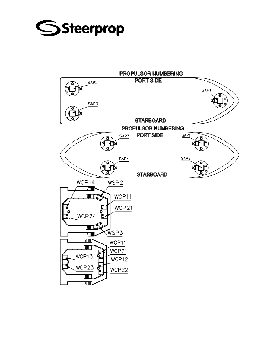
3 P
ROPULSOR NUMBERING
The exact coding in the actual project is shown in the General Arrangement (GA) and
in the control system block diagram (BLD).
The propulsor and control unit numbering is always
shown at CONTROL SYSTEM BLOCK DIAGRAM.
There are following general principles:
¾
PROPULSOR NUMBERING
Propulsor numbering starts from Bow Port Side
and ends to Stern Starboard
¾
CONTROL STATION NUMBERING
Remote control panel numbering starts from Fore
Center station and the next is fore Port Side
station.
¾
CONTROL PANEL WCP NUMBERING
First number is according propulsor
Second number is according control station
¾
WING TYPE CONTROL PANEL WSP
NUMBERING
The controls of all propulsor are mounted into same
panel.
The number is according control station
¾
CONTROL UNITS NUMBERING
The numbering follows the numbers of the
propulsors

C101566-B Page 11 of 67
26.01.2006
© The information contained in this document is the sole property of Steerprop Ltd. any reproduction or disclosure in part or whole without written permission is prohibited.
DOC-1017-1
4 S
TORAGE
4.1 P
ACKING AND PROTECTION
4.1.1 P
ROPULSOR
A unused unit is kept inside.
If the storage period is longer than three moths, the unit is filled with oil. A unit filled
with oil is kept in a upright position.
4.1.2 P
LANETARY GEARS
For extended storage of more than 6 months, the rotating seals will no longer be
efficient. It is recommended to check them periodically by turning the internal gears by
and rotating the input shaft. For a negative multi-disk brake, release the brake by using
a hydraulic pump or similar device It is recommended to replace the gaskets when the
machine is started.
4.1.3 H
EAT EXCHANGERS
4.1.3.1 S
TANDARD CONSERVATION
(
CONTROLLED CONDITIONS
)
All heat exchangers supplied by Bloksma are treated with a rust preventive layer (on
both shell- and tubeside). This layer will protect the heat exchanger when it is stored at
controlled conditions, i.e. inside, in a dry room at constant temperature . When these
conditions are met, the heat exchanger can be stored without special treatment for a
longer period (up till 24 months). The rust preventive layer can be removed with a
mineral solvent (petroleum).
4.1.3.2 A
DVISE FOR CONSERVATION
(
UNCONTROLLED CONDITIONS
)
When the above mentioned storage conditions are not met, you will have to fill the heat
exchanger with an inert gas and all openings have to be closed airtight (additionally
silica gel can be added to absorb liquids). Alternatively, the heat exchanger can be
treated with a rust preventive liquid of a type suited for long term conservation. When
necessary contact a specialised company. Take the materials of the heat exchanger
(see specification sheet) into consideration. Be aware that in uncontrolled storage
conditions large amounts of water can accumulate in the heat exchanger as a result of
condensation.
4.1.4 C
ONTROL SYSTEM AND PROPULSORS ELECTRONIC COMPONENTS
All gears should be greased (Transmitter unit STU).
Place for storing electronic equipments have to have walls and cover. Equipment
should be placed 1 m above the floor to avoid moisture from the floor to get to
equipment. The place should be dry and warm enough (> 10
°C) but not too warm (<
70
°C). Also the temperature should be steady.
In the store with electronic equipment should not be any corrosive material (batteries
with acid).

C101566-B Page 12 of 67
26.01.2006
© The information contained in this document is the sole property of Steerprop Ltd. any reproduction or disclosure in part or whole without written permission is prohibited.
DOC-1017-1
4.1.4.1 P
ACKAGES
Some packing material should be used, for example board chips. But in
some cases it is important that the chips can’t go inside for example control
levers and panels.
Control panels and equipments have to cover first with condense protecting
packing board or similar. Also packing should be steady enough and not
corrosive.
Inside every electronic unit and packing containing electronic equipment
should be moisture absorber to keep components dry. The absorber
material should be kept in order by changing it regularly.
Plastic should not touch straight to any metal and cause any condense and
prevent moisture reduction from packages.
If necessary, you should provide and use special packages meant for
electronic components.
All holes of electronic units should be blocked to avoid dirt and moisture
getting inside the unit.
Packing should be made so that electronic units and components can’t
move inside packing.
Moving and unnecessary opening of packing should be avoided. If packing
is opened it should be closed properly if storing continues.
4.1.5 S
UPERVISION UNDER STORAGE TIME
Frequent checking of store should be done.
4.2 E
ND OF STORAGE
4.2.1.1 C
HECKING
When you take the units from storage, you should check:
That there is no damaged devices or components
All part and components are left
That there do not appear corrosion or condensed corrosion
That lubrication or hydraulic systems do not have rubbish or water
4.2.1.2 C
LEANING
After storing the equipment should be checked that they are not damaged and they are
containing all needed components. Any dust, salt, etc. should be cleaned away with
cleaning cloth, which is not getting fluffy.
Also it is important to make sure that equipments are dry and clean before the supply
voltage is connected!
C101566-B Page 13 of 67
26.01.2006
© The information contained in this document is the sole property of Steerprop Ltd. any reproduction or disclosure in part or whole without written permission is prohibited.
DOC-1017-1
5 T
RANSPORT
T
O
PREVENT
INJURIES
OF
PERSONS
AND
DAMAGE
TO
THE
PARTS
ALWAYS
MAKE
SURE
THAT
THE
PARTS
ARE
SAFELY
TRANSPORTED
AND
STORED
.
5.1 P
ROPULSOR
The propulsor is equipped with lifting eyes. During lifting operation you should be
careful, that you not damage projecting parts.
During transportation the propulsor should fasten and protect properly using
appropriate points. During transportation you should be careful.
If the unit does not have lifting eyes, you should lift and transport the unit on suitable
bed.
5.2 H
YDRAULICS AND LUBRICATION MODULES
The lifting is to be done with lifting linen.
Use strong nylon ropes or lifting belts. When using steel cords, protect the edges.
5.3 I
NTERMEDIATE SHAFTING
Use strong nylon ropes or lifting belts. When using steel cords, protect the edges.
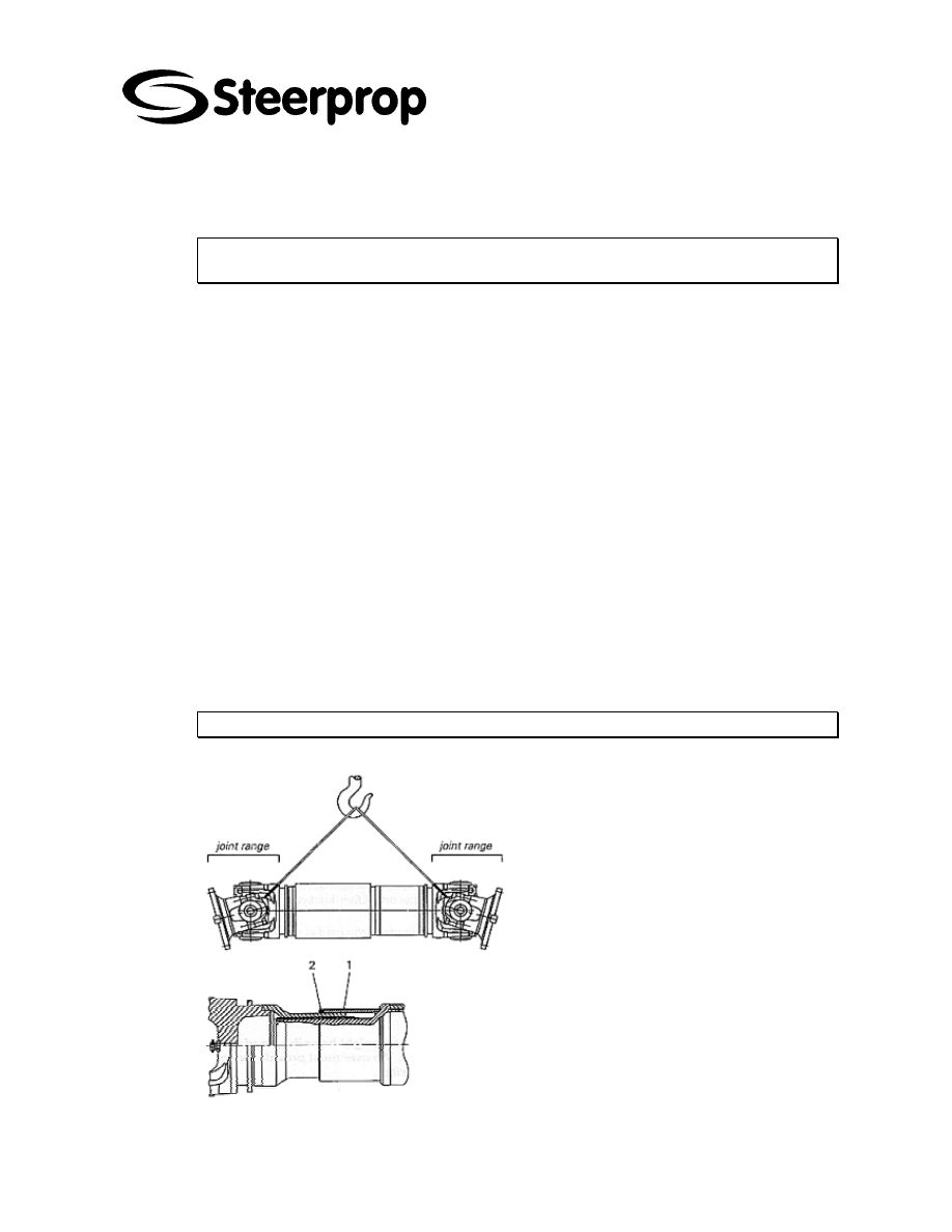
Cardan shafts should be transported in a horizontal position (see illustration). For non-
horizontal transportation additional precautions must be taken to prevent the splined
parts from separating.
D
ANGER OF INJURY
!
Please consider the following precautions:
When lifting or putting down the shaft,
the moving parts (flange yoke and
journal cross) may tilt and lead to
injuries.
Keep hands away from the joint!
Danger of crushed hands!
Do not store or handle the shaft with
any stress or load on the spline
protection (1) or the seal (2).
Avoid bumps and knocks during transport and storage.

C101566-B Page 14 of 67
26.01.2006
© The information contained in this document is the sole property of Steerprop Ltd. any reproduction or disclosure in part or whole without written permission is prohibited.
DOC-1017-1
Use appropriate frames or racks for storage, so that the flange yokes are
not loaded.
Use chocks or blocks to prevent cardan shaft from rolling.
Secure shaft against falling over if it is stored in a vertical position.
Keep cardan shafts in a dry place.
5.4 B
IGGER CONTROL UNITS
All electronic equipment should be transported with care. Lifting should be done only
from marked places or from the bottom of packing.
b
L
IFTING LUGS
For the lifting of the bigger units there are special Lifting lugs / eyes.
b
A
SSEMBLY BRACKETS
Never use assembly brackets for lifting. Lifting destroys them..
There is not allowed to use to control unit the assembly brackets for lifting of the control
units.
5.5 S
MALLER UNITS OR MODULES
All equipment should be transported with care. Lifting should be done only from marked
places or from the bottom of packing.
Smaller do not have any special lifting eyes. Their lifting should be with palette or equal
or with manpower.
C101566-B Page 15 of 67
26.01.2006
© The information contained in this document is the sole property of Steerprop Ltd. any reproduction or disclosure in part or whole without written permission is prohibited.
DOC-1017-1
6 B
OTTOM WELL CASING MOUNTING
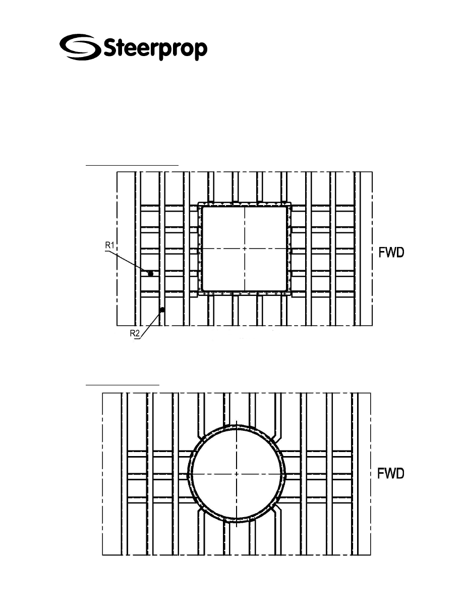
6.1 P
RINCIPAL ARRANGEMENT OF BOTTOM WELL CASING MOUNTING
6.1.1 R
ECTANGULAR CASING
R1 Longitudinal
stiffener
R2 Bottom
frame
6.1.2 C
IRCULAR CASING

C101566-B Page 16 of 67
26.01.2006
© The information contained in this document is the sole property of Steerprop Ltd. any reproduction or disclosure in part or whole without written permission is prohibited.
DOC-1017-1
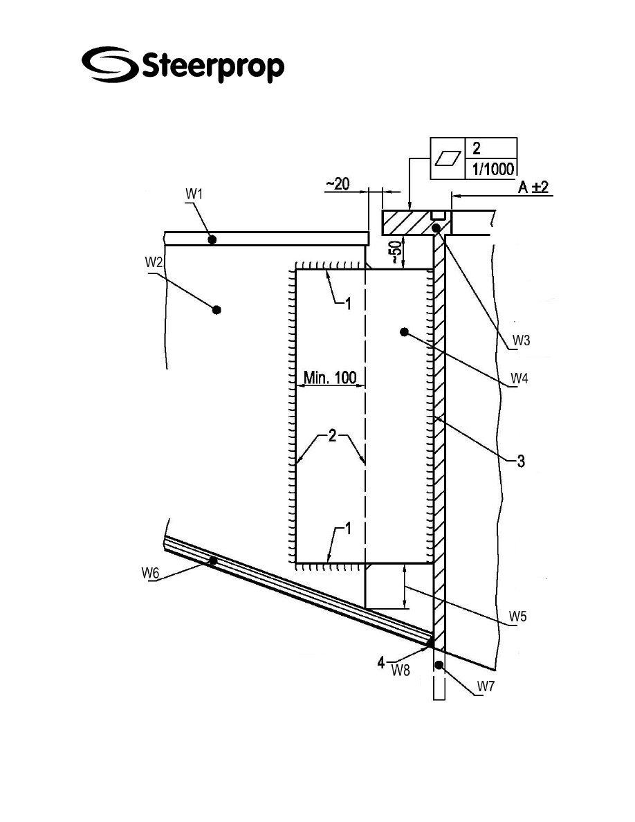
6.2 W
ELDING PROCESS
6.2.1 D
ESCRIPTION OF ITEMS
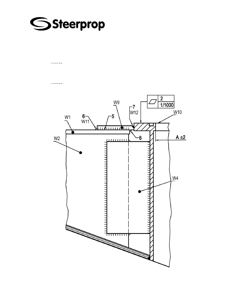
ITEM DESCRIPTION
A Dimension
A
Circular casing diameter
Rectangular casing inner side length
Measured at several positions
W1 Stiffener
flange
W2 Stiffener
web
Mounting plate lap joint to stiffener web plate must be welded edge-by-edge in
sequential order as shown.
Weld throat thickness is determined by strength analysis (normally 25...40 % of plate
thickness).
W3 Bottom
well
casing
W4
Mounting plate (same thickness as stiffener web plate)
All mounting plates must be welded to hull stiffeners before starting to weld to bottom
well casing.
Firstly casing is tack welded to all mounting plates,
After that casing flange flatness and dimension A are checked.
If tolerances are not exceeded, root runs are welded to each joint.
The flatness and dimension A are checked again.
If tolerances are not exceeded, the remaining runs are welded.
After welding is completed, flatness and dimension A are measured and documented.
W5
As small as possible so, that welding can be done properly
W6 Bottom
plate
W7
Working allowance to be cut off after welding
W8
NOTE: Full penetration weld.
W9
Flange supporting plate
W10
Machined surface must be protected during welding
W11
Flange supporting plate lap joint to stiffener flange must be welded edge-by-edge in
sequential order as shown.
Flange flatness and dimension A must be checked after root run has been welded.
After welding is completed, flatness and dimension A are measured and documented.
W12
NOTE: No root cap allowed. Supporting plate is pushed against casing flange and tack
welded at edge 5.
6.2.2 W
ELDING ORDER
Sequential welding order is described with numbers 1-2-3-4-5-6-7.
C101566-B Page 17 of 67
26.01.2006
© The information contained in this document is the sole property of Steerprop Ltd. any reproduction or disclosure in part or whole without written permission is prohibited.
DOC-1017-1
6.3 W
ELDING OF MOUNTING PLATES
C101566-B Page 18 of 67
26.01.2006
© The information contained in this document is the sole property of Steerprop Ltd. any reproduction or disclosure in part or whole without written permission is prohibited.
DOC-1017-1
6.4 W
ELDING OF CASING FLANGE SUPPORTING PLATES
b
N
OTE
1
Flange supporting plates are normally not required. The need of supporting plates are
determined by strength analysis
b
N
OTE
2
All mounting plates must be welded before welding of flange supporting plates.
C101566-B Page 19 of 67
26.01.2006
© The information contained in this document is the sole property of Steerprop Ltd. any reproduction or disclosure in part or whole without written permission is prohibited.
DOC-1017-1
6.5 W
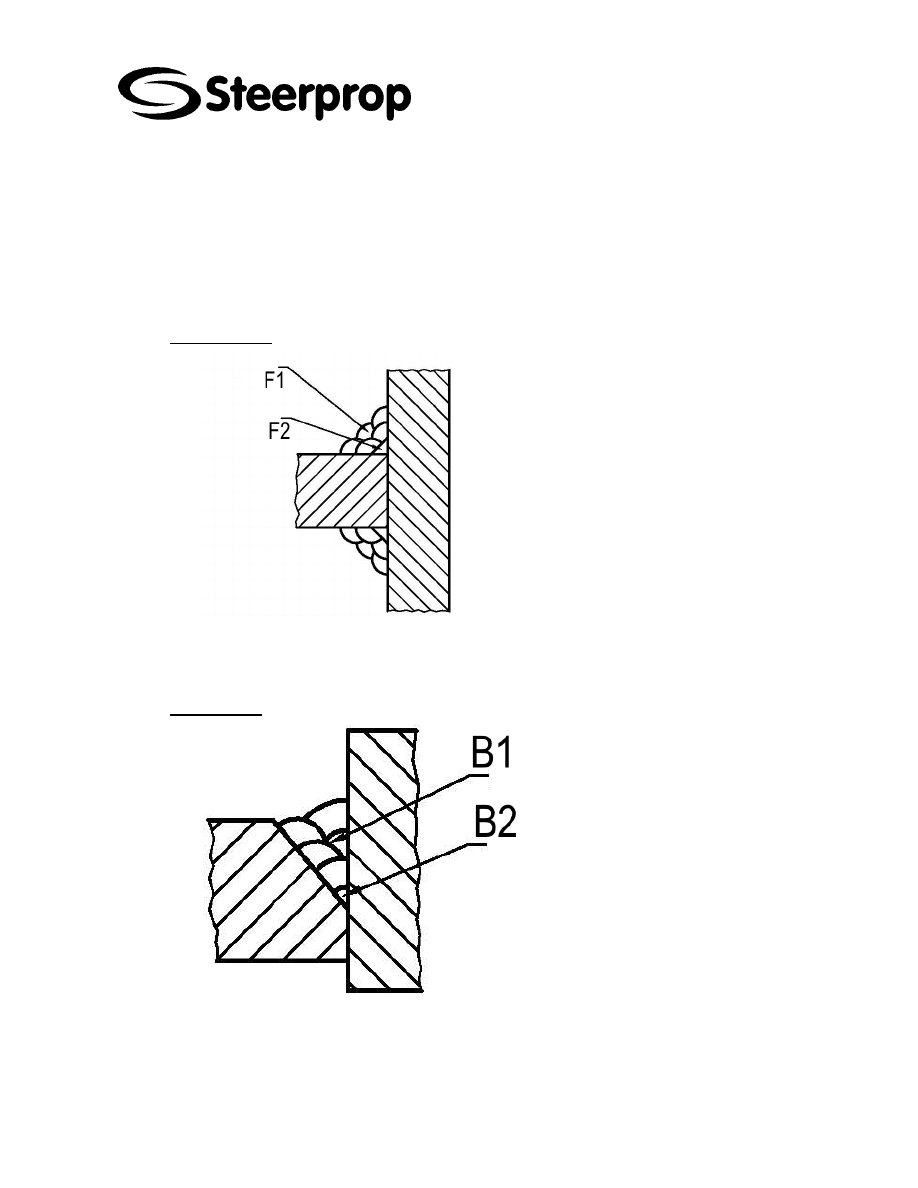
ELD DETAILS
If weld throat thickness exceeds 4 mm, multi-run welds must be used to minimize heat
generation and thus welding distortions.
Root run max. throat thickness 3 mm
Max. throat thickness of filling runs 4 mm
6.5.1 F
ILLET WELD
F1
F2
6.5.2 B
UTT WELD
B1 Filling
runs
B2 Root
run

C101566-B Page 20 of 67
26.01.2006
© The information contained in this document is the sole property of Steerprop Ltd. any reproduction or disclosure in part or whole without written permission is prohibited.
DOC-1017-1
7 I
NTERMEDIATE SHAFT
The intermediate shaft arrangement, dimensions and assembly instruction are given
GENERAL ARRANGEMENT (GA) drawing.
7.1 C
ARDAN SHAFT
See more and updated information from www.gwb-essen.de
GWB cardan shafts are delivered as complete units ready for installation. The shafts
are greased for operation. They are balanced and painted in accordance with the
technical information sheets.
The balance state of a cardan shaft must on no account be altered. An inadmissable
out-of-balance of a shaft may result in uneven running and premature wear of the joints
and the bearings of the units to which the cardan shaft is connected.
In extreme cases the cardan shaft could break and shaft components could be thrown
at speed from the vehicle or machine.
D
ANGER
OF
INJURY
! P
ROVIDE
A
SAFETY
GUARD
DEVICE
!
7.1.1 I
NSTALLATION
In order to guarantee the properties of the cardan shaft as described in the information
brochure they must not be altered from its as-delivered state.
W
HENEVER
PEOPLE
OR
MATERIAL
MIGHT
BE
ENDANGERED
BY
ROTATING
CARDAN
SHAFTS
,
THE
USER
MUST
PROVIDE
FOR
THE
CORRESPONDING
SAFETY
DEVICES
.
Suitable safety devices (e.g. catch bows, solid safety guards) must be provided to
prevent the parts of the shaft from being thrown around.
D
ANGER
TO
LIFE
!
Cardan shafts are elastic and flexural bodies. Their flexural vibration and their critical
bending speed must be calculated. The maximum permissible operating speed must
be sufficiently below the critical bending speed of the first order.
For the smooth running and safety of the shaft the n x ß value (speed x deflection
angle) of the relevant shaft size must not be exceeded.
The faces and the centering diameter of the shaft flanges and companion flanges must
be free of dust, grease or paint to guarantee a safe connection.
Be careful when handling the cardan shaft. Freely moving flange yokes may cause
INJURIES!
Check position of the yokes (1) of the
shaft. Observe the arrow markings (2).
They must be in alignment. The splines
are fitted and must not be exchanged or
distorted.
C101566-B Page 21 of 67
26.01.2006
© The information contained in this document is the sole property of Steerprop Ltd. any reproduction or disclosure in part or whole without written permission is prohibited.
DOC-1017-1
Before installation remove the transport retainer device, if present. In case of doubt
please contact the supplier.
Check the radial and radial runout as well as the spigot fit of the mounted flanges and
the connected units.
Do not turn the joints of the cardan shafts with assembly levers because this may
damage the grease nipples or relief values.
Use nuts and bolts of the prescribed quality (strength).
Only use nuts and bolts in accordance with the supplier's specification.
The bolts should be evenly tightened crosswise with a torque wrench.
When using cardan shafts without length compensation, one of the connecting units
must be flexible in order to be fitted over the flange pilot. Variations in lenght which
may be caused by temperature changes must be allowed for by a suitable connecting
bearing.
If cardan shafts with length compensation are used, the companion flanges must be
firmly fitted on the shafts of the connected units.
Cardan shafts that have been stored for more than 6 month must be relubricated
before use.
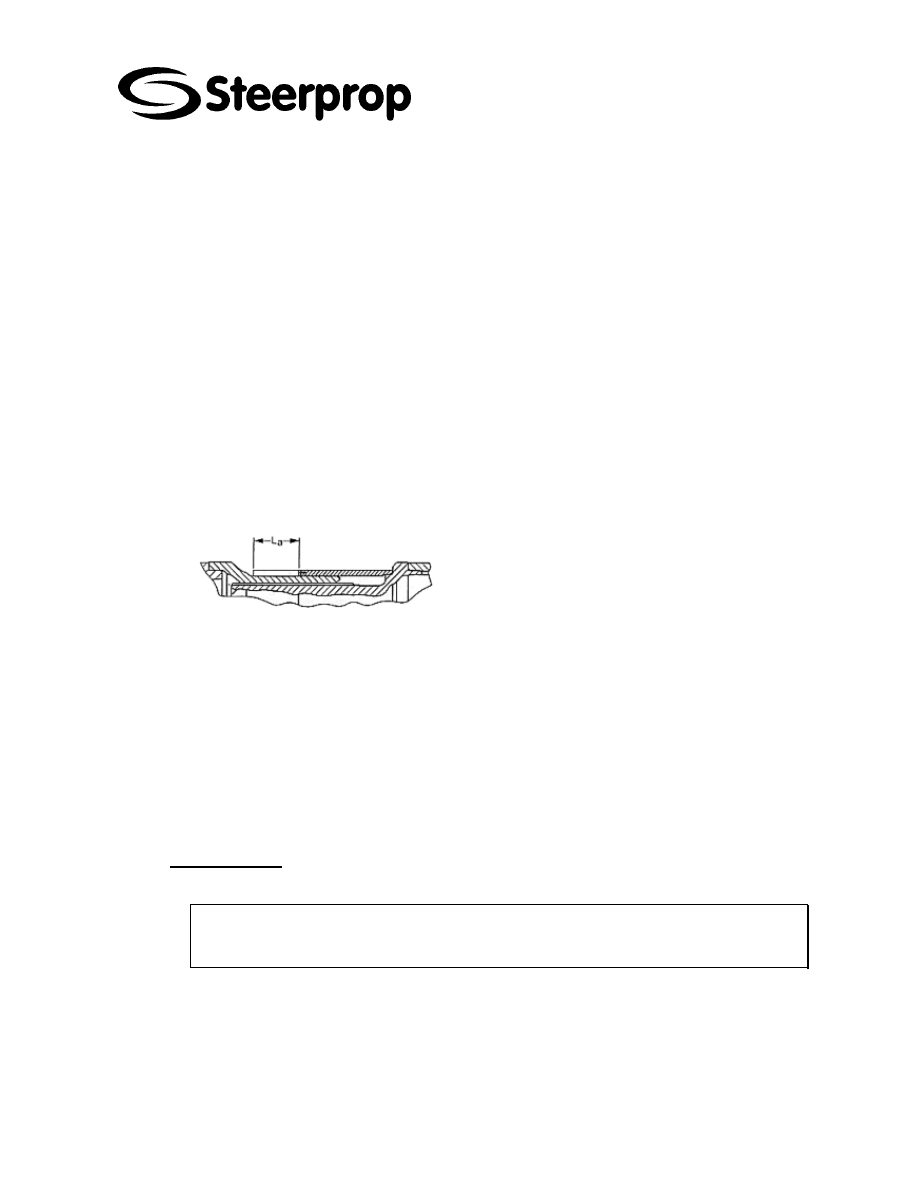
For spray-painting the cardan shaft, make sure
that the sliding range of the seal (length
compensation La) is covered.
For spray-painting the shaft we recommend our paint standards (Please ask for them).
Protect rilsan coated splines (sleeve muff or sleeve yoke) against heat solvents
mechanical damage
When cleaning cardan shafts, do not use aggressive chemical detergents or
pressurized water or steam jets because the seals may be damaged and dirt or water
may penetrate.
Cardan shafts can be used in a temperature range between -25°C (-13°F) and +80°C
(+176°F), up to +120°C (+248°F) but only for limited periods and not on a frequent
basis. Please contact us if the operating temperature deviates from these values.
7.1.2 D
ISASSEMBLY
Before disassembly protect the cardan shaft from spline separation.
S
ECURE THE CARDAN SHAFT AGAINST FALLING DOWN BEFORE PULLING IT OFF
THE COMPANION FLANGE
.
THE FLANGE YOKE MAY TILT
.
D
ANGER OF INJURY
!
Observe the directions for transport, storage and installation of cardan shafts.
C101566-B Page 22 of 67
26.01.2006
© The information contained in this document is the sole property of Steerprop Ltd. any reproduction or disclosure in part or whole without written permission is prohibited.
DOC-1017-1
7.1.3 F
LANGE BOLTINGS
The flange bolting set can be supplied by GWB on request.
The bolt length given in the tables (with assembly papers) are
only suitable if the dimension 2 x G corresponding to the
double the flange thickness G is not exceeded (see data
sheets). If longer bolts are used, check whether the bolts can
still be inserted from the joint side.
We recommended a bolting set consisting of:
Hexagon bolt with short threat similar to DIN 931/10.9 (shaft length greater
than flange thickness)
Self-locking nut, similar to DIN 980/934-10.
The bolts allow fitting
a) partially from the joint side, i.e. the recessed diameter c does not prevent the bolt
from turning;
b) from the companion flange side. We recommend designing the recessed diameter c
1
as locate the bolt head.
See tables for insertion of bolts.
All bolts must be tightened with the specified torque. The tightening torques T
a
given in
the table are based on a 90% (80% hirth-serration) utilization of the elastic limit and
apply to slightly oiled bolts.
Do not use molycote paste or any other grease on the bolts and nuts. In case of
corrosion protected bolts and nuts (eg. Dacromet 500). Please contact us.
Max. permissible tolerance of DIN 25202 class B.
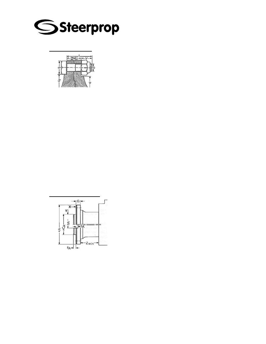
7.1.4 C
OMPANION FLANGES
In general, cardan shafts are connected to the driven units
by companion flanges. The companion flange material
must have a tensile strength of 750 N/mm².
The accurate running of a cardan shaft requires certain
tolerances for the axial and radial run-out.
The dimensions of the companion flanges correspond with those of the same size of
cardan shafts, except for the centring depth F
A
and the fit C
A
the depth of the keyway t
A
and the width b
A
. They can be taken from the following tables.
For better bolt locking we recommend designing the relief of the companion flange as a
bolt head surface and inserting the bolt from the companion flange side. In this case
the distance Z
min
must be met between the flange and the adjacent housing.
If it is not possible to insert the bolts from the companion flange side, we recommend
the use of stud bolts.

C101566-B Page 23 of 67
26.01.2006
© The information contained in this document is the sole property of Steerprop Ltd. any reproduction or disclosure in part or whole without written permission is prohibited.
DOC-1017-1
7.2 I
NTERMEDIATE SHAFT BEARINGS TYPE
SKF
SNL
See the more accurate and updated information from
www.skf.com
. This instruction is
a short version of SKF 5101 E- publication.
7.2.1 M
OUNTING
SNL housings together with SKF bearings are robust and operationally reliable bearing
arrangements, which have long lives. However, if they are to achieve their full potential
and not fail prematurely, they must be properly mounted. Incorrect procedures or
unsuitable tools can influence life negatively.
When mounting the housings it should be remembered that the housings are
asymmetrical internally and therefore the bearings are not always mounted in the
centre of the housing.
Vertical markings on the housing base end faces indicates the location of the centre of
the bearing seating.
7.2.1.1 M
OUNTING THE BEARING
The bearings can be mounted either on a tapered seating – normally for SNL housings
in the form of an adapter sleeve – or on a cylindrical seating. When a bearing is
correctly mounted on a sleeve there will be interference fits between the inner ring,
sleeve and shaft. The degree of interference is determined by how far the bearing is
driven up on the sleeve and either the internal clearance reduction or the axial drive-up
distance can be used as a measure. The clearance reduction in spherical roller
bearings can be measured using a feeler gauge, or the SKF drive-up method can be
used. Information will be sent on request.
For CARB bearings either the clearance reduction or the axial drive-up distance should
be measured. When using a feeler gauge to measure clearance reduction it is
important that the inner and outer rings of the bearing are not displaced with respect to
each other. The SKF drive-up method can also be applied.
Adapter sleeves with the designation OH ..
H in the product tables indicate that the sleeves are provided with the necessary ducts
to enable the bearings to be mounted using the oil injection method. Oil is supplied to
the nut side of the sleeve.
Bearings with cylindrical bore are normally mounted with an interference fit on the
shaft. Appropriate shaft tolerances should be selected (SKF General Catalogue). The
recommendations applying to spherical roller bearings also apply to CARB bearings.
Details of mounting tools as well as the SKF drive-up method can be found on the SKF
CD-ROM MP282 which will
be sent on request.
7.2.1.2 S
UPPORT SURFACE FOR HOUSING BASE
To guarantee long bearing service life it is recommended that the support surface for
the housing is finished to R
a
%
12,5 µm. The flatness (planicity) tolerance should be to
IT7. For moderate demands IT8 may be satisfactory.
C101566-B Page 24 of 67
26.01.2006
© The information contained in this document is the sole property of Steerprop Ltd. any reproduction or disclosure in part or whole without written permission is prohibited.
DOC-1017-1
7.2.1.3 D
OWEL PINS
SNL housings are designed for loads acting vertically to the housing base support. If
they are to be subjected to moderate or heavy loads acting parallel to the base support,
a stop should be provided, or the housing should be pinned to its support.
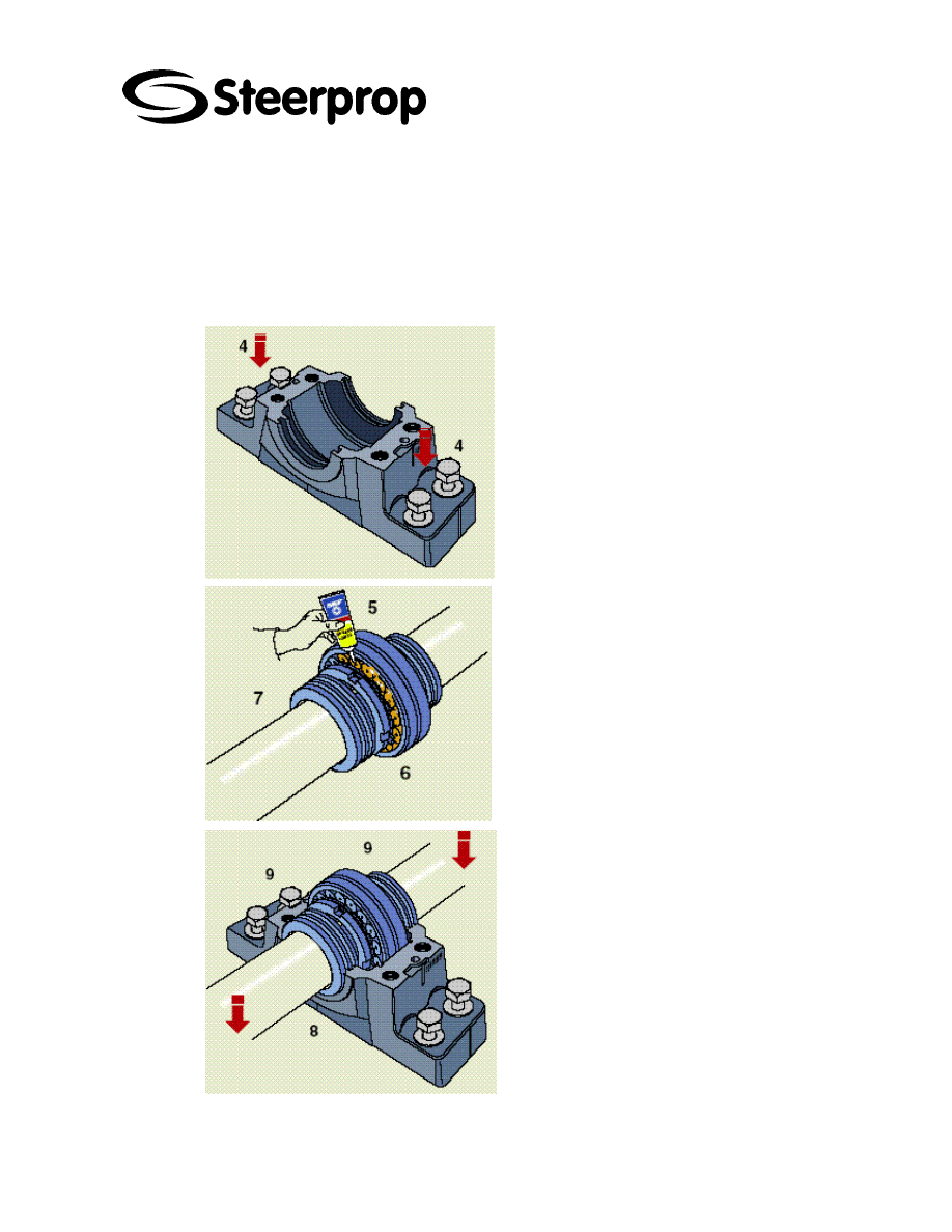
7.3 M
OUNTING
SNL
30
AND
SNL
31
HOUSINGS WITH LABYRINTH
SEALS
Before starting installation work, the following
instructions should be carefully read.
1.
Ensure that the environment is clean. Check
the dimensional and form accuracy of the shaft
seating.
2.
Check that the surface roughness of the
support surface R
a
%
12,5 µm. The flatness
(planicity) tolerance should be to IT7. For
moderate demands IT8 may be satisfactory.
3.
If the bearing is mounted on an adapter
sleeve, determine the position of the housing.
The grease nipple
arranged at one side of the housing cap (for
improved lubrication) should always be at the
side opposite to the sleeve nut. It is necessary
to consider the complete housing as the base
and cap will only fit together as supplied.
4.
Position the housing on the support surface.
Fit the attachment bolts but do not tighten
them.
5.
Mount the first labyrinth seal on the shaft in
the correct position.
6.
Mount the bearing on the shaft – either
directly on a stepped shaft or using an adapter
sleeve. Completely fill the bearing with grease.
The housing base should be filled with grease
up to the markings in each corner inside the
base.
7.
Mount the second labyrinth ring on the shaft
in the correct position. If the housing is to be
used at a shaft end, the second labyrinth ring is
omitted and an end cover inserted in the
housing base instead.
8.
Lay the shaft with bearing and labyrinth
ring(s) in the housing base.
9.
Put the locating ring(s) (when needed) at
each side of the bearing.
NB. Locating rings are only used for locating
C101566-B Page 25 of 67
26.01.2006
© The information contained in this document is the sole property of Steerprop Ltd. any reproduction or disclosure in part or whole without written permission is prohibited.
DOC-1017-1
bearing arrangements, except for CARB
bearings which, although always non-locating,
must always be mounted with locating rings.
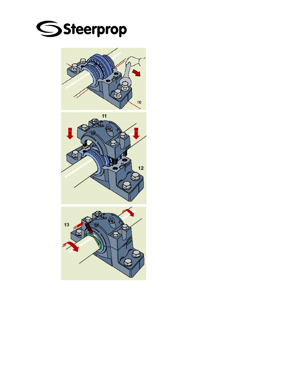
10.
Carefully align the housing base. Vertical
markings on the housing base ends and side
faces showing the bearing seating centre can
facilitate this. Then lightly tighten the
attachment bolts.
11.
The housing cap should be placed over
the base and the cap bolts (to join cap and
base) tightened to the torque
specified in GA.
The cap and base of one housing are not
interchangeable with those of other housings.
The cap and base should be checked to see
that they bear the same consecutive number.
12.
Fully tighten the attachment bolts in the
housing base. Recommended tightening
torques are given in GA.
13.
Finally insert the hollow O-ring cords of
synthetic rubber in the grooves in the labyrinth
rings. This can be done
using a screwdriver while turning the shaft.
C101566-B Page 26 of 67
26.01.2006
© The information contained in this document is the sole property of Steerprop Ltd. any reproduction or disclosure in part or whole without written permission is prohibited.
DOC-1017-1
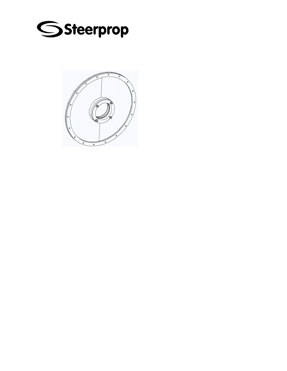
7.4 B
ULKHEAD SEAL
The sealing is self lubricating, but the sealing
tightening flange nuts should be kept in right
tightness as said below:
Check, that nuts are in right tightness. The
tightness is:
Tightened with fingers and ½ turns.
No locking adhesive

C101566-B Page 27 of 67
26.01.2006
© The information contained in this document is the sole property of Steerprop Ltd. any reproduction or disclosure in part or whole without written permission is prohibited.
DOC-1017-1
8 P
ROPULSOR METAL PART PAINTING INSTRUCTIONS
8.1 S
URFACE PRELIMINARY TREATMENT
All foreign matter with harmful affect to preliminary treatment and painting is to be
removed. All water based salts are to be removed with a dirt- and grease-removing
agent according to SFS-EN ISO 12944. The surfaces are pre treated according to
material, as follows:
Steel surfaces: Mill scale and corrosion is removed by blasting to tolerance Sa2½
(SFS-ISO 8501-1). The roughening of sheet metal increases the paint bonding to the
surface.
Priming:
TEKNOPLAST PRIMER 3 white .....................................................1 x 60
µm
8.2 P
ROPULSORS UPPER ASSEMBLY
(
SURFACES INSIDE SHIP
)
8.2.1 P
RIMED SURFACES PRELIMINARY TREATMENT
All foreign matter that has a harmful affect with painting (for example grease and salts)
is to be removed. The surfaces should be clean and dry. Old paint layers that have
exceeded the maximum coating time should be roughened. Damaged places are to be
primed according to the surface and maintenance painting requirements.
The schedule and place for priming is to be selected so that the surface is not
contaminated or wet before further treatment (SFS-EN ISO 12944, part 4).
Painting:
TEKNOPLAST PRIMER 3 gray ......................................................1 x 80
µm
TEKNOPLAST HS 150 RAL 6019 ..................................................1 x 80
µm
Total thickness of coat:
TEKNOPLAST PRIMER 3 white .......................................................... 60
µm
TEKNOPLAST PRIMER 3 gray ........................................................... 80
µm
TEKNOPLAST HS 150 RAL 6019 ....................................................... 80
µm
Total .......................................................................................... 220
µm

C101566-B Page 28 of 67
26.01.2006
© The information contained in this document is the sole property of Steerprop Ltd. any reproduction or disclosure in part or whole without written permission is prohibited.
DOC-1017-1
8.3 P
ROPULSORS LOWER ASSEMBLY
(
SUBMERGED SURFACES
)
8.3.1 P
RIMED SURFACES PRELIMINARY TREATMENT
All foreign matter that has a harmful affect with painting (for example grease and salts)
is to be removed. The surfaces should be clean and dry. Old paint layers that have
exceeded the maximum coating time should be roughened. Damaged places are to be
primed according to the surface and maintenance painting requirements.
The schedule and place for priming is to be selected so that the surface is not
contaminated or wet before further treatment (SFS-EN ISO 12944, part 4).
Painting:
INERTA 165 TM 102.....................................................................1 x 300
µm
Total thickness of coat:
TEKNOPLAST PRIMER 3 ................................................................... 60
µm
INERTA 165 TM 102.......................................................................... 300
µm
Total ................................................................................................... 360
µm
8.4 A
NTIFOULING PAINTING
Over coating of an INERTA 165 epoxy based paint layer has to be done in 24 hours. A
paint coat older than this must be roughened before further coats of paint are applied. If
painted with antifouling paint the procedure used is to be according to the antifouling
paint supplier.
8.5 S
ERVICE AND MAINTENANCE PAINTING
Service and maintenance painting have to do so that the total coat is built up like
instructed above.
Damaged places are to cleaned and roughened carefully. All foreign matter that has a
harmful affect with painting (for example grease and salts) is to be removed. The
surfaces should be clean and dry. The border between old new painting area should
grind smooth. No sharp edges.
8.6 C
ORROSION CONTROL
Cathode protection..............................................zinc or aluminum cathodes
It is not allowed to paint those cathodes.
There are cathodes:
Propulsor body
Nozzle
Bottom well
Propeller shaft seal (there is available a replacement kit)
Inside rope guard

C101566-B Page 29 of 67
26.01.2006
© The information contained in this document is the sole property of Steerprop Ltd. any reproduction or disclosure in part or whole without written permission is prohibited.
DOC-1017-1
9 A
DHESSIVES AND SEALANTS
9.1 T
HREAD LOCKS
9.1.1 S
CREW LOCKING
Loctite 243 general-purpose adhesive is used to lock screws, with the following
exceptions:
Stud bolt metal ends, Loctite 270 or 2701.
Adjusting screws, Loctite 222.
The screws of the outer ring of the slewing ring are leaved without locking
adhesive.
The lower assembly’s and slewing assembly’s cap nuts are locked with wire
by welding.
9.1.2 L
OCKING PLUGS AND HYDRAULIC COUPLINGS
Thread size R ¾” or smaller Loctite 542
Thread size R 1” or larger Loctite 577
9.1.3 M
ECHANICAL ANGLE INDICATORS
Lock the dial and scale screws with Loctite 542
9.1.4 P
ROXIMITY SENSORS
Lock the threads with Loctite 542
9.2 F
LANGE SEALANTS
Loctite 5910 is used as flange sealant.

C101566-B Page 30 of 67
26.01.2006
© The information contained in this document is the sole property of Steerprop Ltd. any reproduction or disclosure in part or whole without written permission is prohibited.
DOC-1017-1
10 P
IPING
10.1 I
NSTALLATION AND PIPING
You should follow the good approach of the servicing and assembly of hydraulic
systems.
You should take care of purity and cleanliness of piping and components and use right
materials and tools.
The final tightness of the system is achieved during the normal operation, when the
impact of the warn oil, vessel vibrations and play are become even.

C101566-B Page 31 of 67
26.01.2006
© The information contained in this document is the sole property of Steerprop Ltd. any reproduction or disclosure in part or whole without written permission is prohibited.
DOC-1017-1
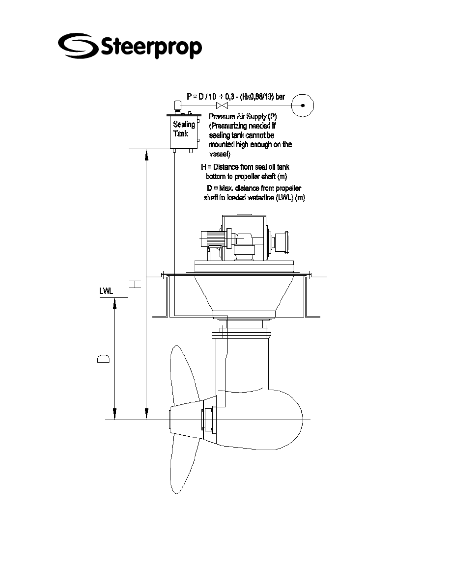
11 P
ROPULSOR SEAL OIL TANK INSTALLATION
11.1 P
ROPULSOR SEAL SYSTEM
The propeller shaft seal has a separate lubrication system equipped with a separate
seal oil tank.
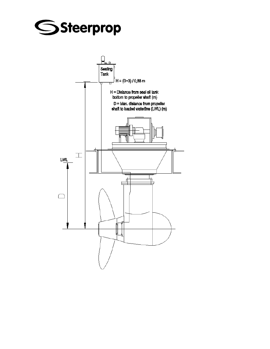
11.2 S
EAL OIL TANK
The system consists of a head tank with low and high level alarm for monitoring
steering tube and propeller shaft seal condition.
The seal oil tank is situated above the waterline and air pressure is adjusted so that the
oil pressure in the blocking chamber is 0.3 bar higher than the water pressure outside
the seal and the oil pressure inside the propulsion unit.
C101566-B Page 32 of 67
26.01.2006
© The information contained in this document is the sole property of Steerprop Ltd. any reproduction or disclosure in part or whole without written permission is prohibited.
DOC-1017-1
11.3 N
ON
-
PRESSURIZED SYSTEM
C101566-B Page 33 of 67
26.01.2006
© The information contained in this document is the sole property of Steerprop Ltd. any reproduction or disclosure in part or whole without written permission is prohibited.
DOC-1017-1
11.4 P
RESSURIZED SYSTEM

C101566-B Page 34 of 67
26.01.2006
© The information contained in this document is the sole property of Steerprop Ltd. any reproduction or disclosure in part or whole without written permission is prohibited.
DOC-1017-1
12 O
IL FILLING
12.1.1 OIL
PURITY
GRADE
The purity grade of the used oil should be at least according to standard 17/14 ISO
4406. The oils from suppliers do not normally fulfill the required purity grade. To avoid
the impurities from barrel or tank to get into the unit the oil is pumped, when filling the
propulsor, through a 10-micron fine filter. The propulsors filling connection/valve is
located at the fwd part of the upper assembly.
12.1.2 OIL
FILLING
The propulsor and sealing oil tank have to be filled with oil before the propulsor or ship
is lowered in water. In addition, the piping from the sealing oil tank to the propulsors
seal is filled and bleeding carefully before lowering to water.
12.1.3 FILLING
AND
BLEEDING
THE
PROPELLER
SHAFT
SEALING
The filler and purge caps are located on the seal frame. The locations of the caps are
shown on the seals drawing you can find in a separate manual concerning the propeller
shafts seals maintenance instructions.
The rope guards are removed when filling seals or when bleeding.
12.2 O
IL DRAINING AND PUMPING OUT
b
OIL
DRAINING
FOR DRAINING, THE PROPULSOR IS TURNED TO Z-
POSITION (THE PROPELLER SHAFT IS ALIGNED WITH
THE DRIVE SHAFT, PROPELLER BACKWARDS.
At the shipyard, the plug at the bottom of the lower assembly carries out
the oil draining. There is a valve in the plug that prevents the oil from
leaking out, when the plug is removed. For draining the oil, an adapter
M000222A opens the valve when screwed into z-position. A hose is
connected to the pipe so the oil drains into a waste oil container.
The oil can be drained also when the ship is not at the shipyard with a
circulation / draining pipe situated inside the unit.
b
PUMPING
THE
OIL
OUT
For emptying the unit the suction of the external pump (ship equipment)
will be connected to the filling / emptying connection (1 1/2" BSPP female)
with ball valve.
Oil is pumped until it starts sucking air. Then the oil level is low enough to
open the flange where the ball valve is attached and there is a pipe, which
goes to the lowest point of the propulsor visible.
Steerprop toolset includes an adapter M000222A, which can be screwed
to that connection and attached to the suction hose. Pumping can be
continued until the propulsor is empty of oil.

C101566-B Page 35 of 67
26.01.2006
© The information contained in this document is the sole property of Steerprop Ltd. any reproduction or disclosure in part or whole without written permission is prohibited.
DOC-1017-1
12.3 C
HECKING OIL QUANTITY
For checking oil quantity there are sight gauges on the oil control unit at the aft
part of the upper assembly to indicate minimum level and maximum level. The oil
quantity is checked when the propulsor is not running and oil is cold. When
checking the oil level you need to consider:
When the unit is running the oil level is lower and is not shown in sight
gauges. The lower level switch is monitoring the oil level.
When unit is warm from operation but not running, the oil level is above the
maximum level because of thermal expansion.

C101566-B Page 36 of 67
26.01.2006
© The information contained in this document is the sole property of Steerprop Ltd. any reproduction or disclosure in part or whole without written permission is prohibited.
DOC-1017-1
13 H
YDRAULIC SYSTEMS
13.1 G
ENERAL
13.1.1 L
ONG SERVICE LIFE AND FUNCTIONAL RELIABILITY OF HYDRAULIC SYSTEMS
AND THEIR COMPONENTS ARE DEPENDENT ON CORRECT HANDLING
Long service life and functional reliability of hydraulic systems come from all parts of
the system. All components, equipment and pipes should be delivered clean and well
protected against all dirt that prevails at workshops and sites.
All ports of hydraulic power units, valves, cylinders and hydraulic motors
should be properly plugged.
Plugs, caps or blind flanges should not be removed until absolutiy
necessary.
All pipes delivered to site must be free from scale, rust and pickling residue.
Ensure fault-free operation by taking note of:
The special installation and operating instructions for the system
In individual cases the special instructions
The technical data contained in the catalogue sheet
When selecting pipes, hoses and fittings / flanges, the correct pressure
rating has to be selected (wall thickness, material). Only cold drawn
seamless tube is to be used.
Do not use hemp and putty as sealing materials, as these can lead to
contamination and thus to malfunctions!
13.2 A
SSEMBLY
13.2.1 A
SSEMBLY PREPARATION
Ensure that the system is dean
13.2.1.1 F
OR THE ENVIRONMENT
Power units, pipe connections, components (e.g. pickling may be
necessary if a hot process has been carried out, e.g. welding, hot bending,
etc.), are to be kept dean, e.g. cleaned
13.2.1.2 F
OR THE PRESSURE FLUIDS
Watch out for contamination, dampness; contamination from the
environment must not be allowed to enter the tanks!
Fill oil tanks only via a filter preferably via system filters or portable filter
stations with fine filters.
Protective internal paint coatings, if used, must be resistant to the pressure
fluid to be used!
13.2.1.3 F
OR STOCK PARTS
Storage of parts which have not been filled or treated with anti-corrosion
fluid can lead to the build-up of resin. Dissolve the resin and renew the
lubricating film.
Check to see that all of the parts required for assembly are available!

C101566-B Page 37 of 67
26.01.2006
© The information contained in this document is the sole property of Steerprop Ltd. any reproduction or disclosure in part or whole without written permission is prohibited.
DOC-1017-1
Take note of any transport damage!
13.2.1.4 F
OR PUMPS
On pumps taken from stock, resin may have formed.
This must be removed by means of solvents. Then, the lubricating film must
be renewed. No special measures have to be taken for fire-resistant fluids.
13.2.2 C
ARRYING OUT ASSEMBLY
Make use of lifting facilities and transport equipment!
Do not use force. to minimise shearing forces and tension on pipelines and
components. The valve mounting surfaces must be flat. The fixing bolts
have to be evenly tightened to the stated torque.
Take care to ensure that the pipes are adequately fixed (pipe clamps)!
In order to avoid external leakage, take note of the installation instructions
of the pipe fittings manufacturer. We recommend the use of fittings with
flexible seals.
Make sure hose lines are correctly laid! Rubbing and abutting of the lines
must be avoided.
Availability of the correct pressure fluids
13.2.2.1 S
ELECTED ACCORDING TO SYSTEM REQUIREMENTS
,
PLEASE NOTE
:
Viscosity of the hydraulic fluid
Operating temperature range
Type of seals we don the components fitted
13.2.2.2 P
UMPS
Stress-free installation
In the case of prime movers, ensure that foundations are level
13.2.3 L
INES AND CONNECTIONS
13.2.3.1 S
UCTION LINES
Design and assemble suction lines according to the manufacturer’s
instructions.
Suction vacuum pressure or feed pressure are within the limits specified by
the manufacturer; filters and valves possibly installed must be taken into
account.
Take care that the suction lines are leak-free
The flow velocity in the suction line should not exceed 0.5 m/s.
The pipe ends should be cut at an angle of less than 45 degrees and
installed at a distance of at least 2.5 x the pipe diameter from the tank floor
in order to prevent the aspiration of deposits from the tank floor.
13.2.3.2 D
RAIN LINES
Use a sufficient nominal width in order to keep the backpressure in the
housing within the permissible limits.
When installing the line make sure that the housing is completely filled with
fluid, while taking care that a siphoning effect is avoided.
Pressureless return to the tank
Sufficient cooling and settling of the hydraulic fluid is achieved by directing
the hydraulic fluid to the tank wall.

C101566-B Page 38 of 67
26.01.2006
© The information contained in this document is the sole property of Steerprop Ltd. any reproduction or disclosure in part or whole without written permission is prohibited.
DOC-1017-1
Ensure a sufficient distance to temperature switches.
13.2.3.3 I
NSTALLATION INSTRUCTIONS
All lines have to be submerged at least 2.5 x the pipe diameter below the
lowest permissible fluid level, however, at least 100 mm in order to prevent
foaming.
Install the drain line higher than the suction line and take precautions that
the returned oil cannot be directly re-aspired.
The ends of the suction, return and drain lines must therefore be installed
with a distance of at least 200 mm from each other.
We recommend seamless precision steel pipes to DIN 2391 and releasable
pipe connections.
13.2.4 F
ILTERS
Whenever possible, use return line or pressure filters.
Use suction filters only in conjunction with vacuum pressure switches /
clogging indicators.
Depending on the pump type the required filter rating is 25 um to 40 um.
Recommendation: 10
µm filters prolong the service life under high load
conditions.
13.2.5 H
YDRAULIC FLUIDS
13.2.5.1 M
INERAL OILS
When using HL oils without wear-reducing additives, vane pumps (V3, V4,
PV7, PVV, PVQ) may only be operated at reduced pressure.
Oils containing polar additives (slide way oils) must not be used for pumps
with plain bearings, as the additives separate at 70 C and thus impair
cooling and lubrication of the bearings.
13.3 C
OMMISSIONING
When assembly has been carried out correctly, it is possible to proceed with
commissioning and functional testing.
13.3.1 P
REPARATIONS FOR A TRIAL RUN
Tank cleaned?
Pipelines deaned and correctly fitted?
Fittings, flanges, tightened?
Pipelines and components correctly connected in line with installation
drawings or circuit diagram? ...........................................................................
Is the accumulator filled with nitrogen? Nitrogen is to be filled until the pre-
charge pressure -- as stated in the circuit diagram, is reached. (On the fluid
side the system has to be at zero pressure’) It is recommended that the gas
pre-charge pressure is noted on the accumulator (e.g. sell-adhesive label)
and in the hydraulic circuit so that a compartory check may be made later if
required.
A
TTENTION
! O
NLY
USE
NITROGEN
AS
THE
PRE
-
CHARGE
GAS
! T
HE
ACCUMULATOR
MUST
COMPLY
WITH
THE
SAFETY
REGULATIONS
WHICH
APPLY
AT
THE
PLACE
OF
FINAL
USE
Are the drive motor and pump correctly assembled and aligned?

C101566-B Page 39 of 67
26.01.2006
© The information contained in this document is the sole property of Steerprop Ltd. any reproduction or disclosure in part or whole without written permission is prohibited.
DOC-1017-1
Is the drive motor correctly connected?
Does the filter comply with the required filter rating
Is the filter fitted in the correct direction of flow?
Has the specified pressure fluid been filled up to the maximum oil level?
A
S
THE
PRESSURE
FLUID
OFTEN
DOES
NOT
MEET
THE
REQUIRED
CLEANLINESS
,
FILLING
MUST
TAKE
PLACE
VIA
A
FILTER
. T
HE
ABSOLUTE
FILTER
RATING
OF
THE
FILLING
FILTER
SHOULD
BE
AT
LEAST
THAT
OF
THE
FILTER
WHICH
IS
FITTED
IN
THE
SYSTEM
.
13.3.1.1 E
LECTRICAL OPEN AND CLOSED
-
LOOP CONTROL ELEMENTS
Observe voltage and current values
13.3.1.2 D
IRECTION OF ROTATION OF DRIVE
/
DRIVEN SHAFTS
Observe directional arrow
Testing of a unit filled with hydraulic fluid:
Switching the unit briefly on and off prevents damage in the case of the
wrong direction of rotation.
13.3.1.3 F
ILLING
Pump types V3, V4, PV7, PVV, PVQ are self-priming, the houses need not
to be filled. Internal gear pumps have to be filled prior to commissioning!
For all other pumps, verify whether the housing must be filled.
13.3.2 S
TART
-
UP
Observe specific component instructions.
Set all valves, especially on the suction and supply side, to the free-flow
position.
Switch the motor briefly on and off several times in order to facilitate
bleeding. Only operate the pump under full load when it operates properly
and smoothly.
During initial start-up, bleed the pressure line to allow complete filling of the
pump.
Exceptions to this are pumps with automatic bleed valve.
When the system starts up, the fluid level in the tank must not fall below the
minimum suction level.
13.3.2.1 P
RESSURE LIMITATION
/
PRESSURE CONTROL
Always select the lowest settings for commissioning.
Carefully increase the pressure to the required values, but do not set to
unnecessarily high values.
If required, secure settings against unwanted adjustment.
13.3.2.2 T
EMPERATURE
Check the fluid temperature under normal operating conditions.
13.3.3 T
RIAL RUN
13.3.3.1 P
REPARATION FOR STARTING
For safety reasons only personnel from the machine manufacturer and
possibly maintenance and operating personnel should be present.

C101566-B Page 40 of 67
26.01.2006
© The information contained in this document is the sole property of Steerprop Ltd. any reproduction or disclosure in part or whole without written permission is prohibited.
DOC-1017-1
All pressure relief valves, pressure reducing valves and pump pressure
controllers are to be set to zero. The exception to this are TÜV set valves.
Are the isolator valves fully open!
Switch on briefly and check so see that the drive motors direction of rotation
matches that of the pump.
Check the position of the directional valves and, if necessary move them
into the required switched position.
Set the control valves to by pass.
Open the pump suction valves. If necessary, dependent on the design, fill
the pump housing with pressure fluid, to avoid the bearings and rotary
group components from running dry
If there is a pilot oil supply pump this should also be commissioned.
Start the pump, move it out of its zero position and listen for any noises.
Swivel the pump out a little. (approx. five (5) degrees) As far as possible
using the built-on controller otherwise operate with the full flow With
combustion engines they are to be run at the idle speed.
13.3.3.2 S
YSTEM BLEEDING
Bleed the system
Carefully loosen fittings (at high points in the system) or bleed screws.
When the escaping fluid is free of bubbles then the filling process is
complete. Re-tighten the fittings.
13.3.3.3 S
YSTEM FLUSHING
Before commissioning of hydraulic systems, it is necessary to flush out all
contamination in order to achieve long service life and trouble free function.
Cleanliness levels are specified by product manufacturer and should be
adheared to.
To carried out the flushing, using the system pumps, is generally
inadequate, as the flow velocities will be too low. Rushing procedures
require a proper flushing unit to obtain the correct velocities, temperatures
and pressures specifications.
Closed and semi-closed hydraulic systems must always be flushed with a
flushing unit.
b
P
REPARATION THE SYSTEM FOR FLUSHING
Before beginning with the flushing procedure, it is important to remember
that pumps, valves and actuators are bypassed using pipes, hoses or
flushing plates where possible.
Effective flushing is achieved if a turbulent flow is created. In straight and
smooth pipe the flow becomes turbulent if the Re > 4000 (Reynolds
number)
High flushing velocities and low viscosities increase the effect of flushing.
Recommended flushing temperature for mineral oils is 60 C. Minimum
viscosity however is determined by the flushing pumps. The flow velocity
should be at least twice the speed of normal operational speeds.
b
B
EFORE FLUSHING
.
Ensure the flushing unit is cleaned before starting. Flushing fluid must be
pumped trough a filter (5-10 ìm (3 ìm, âx = 100) into the tank of the flushing
unit and the function of all indicators must be verified (dogging indicators,
oil level switches and thermostats ) before start up. Filter elements

C101566-B Page 41 of 67
26.01.2006
© The information contained in this document is the sole property of Steerprop Ltd. any reproduction or disclosure in part or whole without written permission is prohibited.
DOC-1017-1
required, in accordance with oil cleanliness level which is to be obtained,
must be inserted into the flushing unit.
The piping system must be vented before starting of the flushing procedure.
b
F
LUSHING
Heat the fluid to the required temperature (viscosity).
With servo systems the servo valves are to be removed and replaced by
flushing plates or directional valves of the same nominal size. The actuators
are to be short circuited. During flushing the pressure fluid within the
hydraulic system should reach a temperature that is at least as high as the
subsequent operating temperature. The filter elements are to be replaced
as required.
Flush the system, if possible by short circuiting the actuators, until the filters
remain dean; Check the filters!
As a flushing time the following can be applied or until the required
cleaness class has been reached.
While flushing is in progress keep a dose watch on the dogging indicators
of the filters so that the elements can be changed at the right lime.
It is adviseable to reverse the direction of the flow after about an hour of
flushing, If changing of the flow direction is (in practice) impossible then
flushing must continue for at least 3-4 hours longer. When the clogging
indicators do not react after an hour, fluid samples should be taken to verify
particle count microscope examination for contamination with oppticle
particle counter). When it is possible to use an automatic particle counter
during the flushing process and the cleanliness of the returning fluid is
immediately known, then, when the required level of the cleanliness has
been achieved, flushing should be terminated.
If the used flushing fluid is not the required hydraulic fluid for the system.
The fluid must be drained completely from the hydraulic system.( Ensuring
the correct fluid is filtered before being placed into the system)
b
A
FTER FLUSHING
At the end all bypass pipings, hoses and flushing plates must be removed.
The hydraulic system must be restored to its former condition. Keeping
cleanliness in mind.
Check the system functions without load, if possible control by hand; Cold
test the electro hydraulic controls.
After the operating temperature has been reached, test the system under
load; slowly increase the pressure.
Check monitoring and measuring devices!
Check the housing temperature of the hydraulic pumps and motors
Listen for noises!
Check the oil level, if necessary top up!
Check the settings of the pressure relief valves by loading or braking the
system.
Check for leaks
Switch-off the drive
Tighten all fittings even if there is no evidence of leakage.
A
TTENTION
! O
NLY
TIGHTEN
WHEN
THE
SYSTEM
IS
NOT
UNDER
PRESSURE
!
Is the pipe fixing adequate even under changing pressure loads?
Are the fixing points correct?
Are the hoses so laid that they do not rub, also under pressure?
Check the pressure fluid level

C101566-B Page 42 of 67
26.01.2006
© The information contained in this document is the sole property of Steerprop Ltd. any reproduction or disclosure in part or whole without written permission is prohibited.
DOC-1017-1
Full functional test of the system. Compare the measured values with the
permissible or required data (pressure. speed, setting further control
components.)
Jerky movements indicate amongst other things, the presence of air in the
system. By briefly swivelling the pump in one or both directions with the
actuator in the loaded or braked condition, it is possible to eliminate certain
air pockets. The system is completely bled when all functions can be
carried out jerk-free and smoothly and there is no foaming on the surface of
the pressure fluid. In practice it has been found that foaming should have
ceased one hour after start-up.
Check the temperature
Switch-off the drive
Remove filter elements, off-line and main filters and inspect for residues.
Clean the filter elements or replace. Paper or glass fibre elements camot be
cleaned.
If further contamination is found then additional flushing is required in order
to prevent premature failure of the system components
All of the settings carried out should be documented in an acceptance
certificate.
b
D
OCUMENTS
All documentation from the flushing procedure must be put together Analysis of
cleanliness, description of flushing procedure, list of equipments used, personnel in
charge, etc.
13.3.4 T
HE MOST COMMON FAULTS OCCURING DURING COMMISSIONING
In conjunction with maintenance. commissioning is very decisive for the service life and
functional safety of the hydraulic system. That is why faults must, as far as possible. be
minimised during commissioning.
13.3.4.1 T
HE MOST COMMON FAULTS ARE
:
The fluid reservoir has not been checked.
The operating fluid was filed unfiltered.
The installation was not checked before commissioning (subsequent
conversion with loss of fluid!).
System components were not bled of air.
Pressure relief valves are set too close (slightly higher) to the working
pressure (switching pressure differentials not taken into account).
Hydraulic pump pressure controllers are set higher or to the same pressure
as the pressure relief valves.
The flushing time for servo systems was not adheared to.
Abnormal pump noises were not taken into account (cavitation, suction line
not air tight, too much air in the pressure fluid).
Shear loads on cylinder rods not taken into account (installation error!).
Hydraulic cylinders were not bled (seal damage!)
Limit switches adjusted too dose.
The pressure switch switching hysteresis was not taken into account during
setting up.
Hydraulic pump and hydraulic motor housings were not filled with pressure
fluid before commissioning.
The set values were not documented.
The adjustment spindles were not secured or sealed.
Unnecessary personnel were present at the system during commissioning

C101566-B Page 43 of 67
26.01.2006
© The information contained in this document is the sole property of Steerprop Ltd. any reproduction or disclosure in part or whole without written permission is prohibited.
DOC-1017-1
13.3.5 S
PECIAL OPERATIONS AFTER COMMISSIONING WITH THE FILTERS
During commissioning, in intervals of two to three hours and, if necessary
clean.
During the first week daily and if necessary clean.
13.3.6 S
PECIAL OPERATIONS AFTER COMMISSIONING WITH THE OIL LEVELS
Continuously during commissioning
For a short period after commissioning

C101566-B Page 44 of 67
26.01.2006
© The information contained in this document is the sole property of Steerprop Ltd. any reproduction or disclosure in part or whole without written permission is prohibited.
DOC-1017-1
14 P
ROPULSOR COOLING SYSTEM INSTALLATION
14.1 C
ONSTRUCTIONAL DIRECTIONS IN A PIPING DESIGN
.
Pay attention to the following points:
Level and square mounting possibility.
Bends in the piping have to be located at a distance of at least three times
the nominal diameter of the pipe from the inlet of the heat exchanger.
When a vaporizing cryogenic medium is used, the heat exchanger has to
be placed under an angle of 3° - 10°, in order for the vapor to be able to exit
the heat exchanger, helped by natural circulation.
Check if vent and drain connections are present in both circuits of the heat
exchanger (when not on the heat exchanger then make them in the piping).
Put a filter (with a permeability of 3 mm.) before the inlet of both circuits of
the heat exchanger.
Stress- and vibration free mounting possibility of the connections and the
supports (fit expansion bellows and/or silencer blocks when necessary).
Disassembling possibility of the tubebundle (and other parts like drain and
vent plugs).
Expansion possibility of lockable liquid circuits.
Danger of freezing of liquid circuits.
The design data of the heat exchanger on the the drawing. For instance
the flows: deviating from them can cause unacceptable high or low
velocities. A (temporary) lower flow is acceptable when caused by a control
system and a conditioned circuit is involved. Avoid standstill (unless the
heat exchanger is drained and flushed with fresh water).
When adding an inhibitor to one of the fluids in the heat exchanger, always
check whether this inhibitor can be harmful for the materials of the heat
exchanger (see specification sheet).
Make sure that in case of flow control (with conditioned circuits only) this is
done gradually (no ‘on-off-control’).
Although this will almost never occur in practice, Bloksma reserves the right
(according to TEMA RGP-RCB-2) to plug a maximum of 1% of the tubes.
Always check whether both fluids are compatible with the materials of the
heat exchanger; Bloksma chooses the materials judging on the fluids
specified by the customer, but is often not well informed about possible
contaminations, higher or lower than normal degrees of acidity and other for
the choice of materials important proprties.
Check whether the materials of the connecting piping are compatible with
the materials of the heat exchanger (when the materials of the bundle are,
from a corrosion point of view, weak in comparison with the materials of the
piping, the bundle will corrode faster than expected).
14.2 I
NSTALLATION AND START
-
UP
14.2.1 R
ECEIPT
At receipt check the packaging and the heat exchanger:
report any damage to supplier
compare the data on the nameplate, confirmation of the order and on the
drawing

C101566-B Page 45 of 67
26.01.2006
© The information contained in this document is the sole property of Steerprop Ltd. any reproduction or disclosure in part or whole without written permission is prohibited.
DOC-1017-1
check whether or not the correct instruction manual is present by
comparing the article number on the cover sheet with the article number of
the instruction manual on the confirmation of order
Always store the heat exchanger in a dry room, free of large temperature
changes. When the heat exchanger is not being put into operation
immediately after receipt, follow the storage instructions.
14.2.2 I
NSTALLATION
Warning: Beware of any rust preventive layers (see “Instructions for conservation”) that
might still be present in the heat exchanger before proceeding.
Remove all protective plugs and covers from the connecting flanges prior to
installation of the heat exchanger.
A 1- or 3-pass model (tubeside) has to be mounted in such a way that shell-
and tubeside will be in counterflow.
Check whether the positions of the vent and drain connections on the heat
exchanger correspond with the mounting position of the heat exchanger.
In models with body side wire connections, check to see if the couplings
with which the lines are fastened do not touch the bundle.
Mount the heat exchanger level and square on a flat surface in order for the
pipe connections to be made without forcing.
Do not weld anything to the heat exchanger.
Mount one support in a fixed position, while the other one is mounted in
such a way that it is able to slide in the direction of the longitudinal axis of
the heat exchanger. The heat exchanger will thus be able to expand under
thermal stress.
Before connecting piping to the heat exchanger flanges, make sure that the
gasket surface is clean and free from scratches and other defects. Always
use new gaskets, of the correct type and tighten the bolts crosswise.
Take care when lifting the heat exchanger. Use at least two hoops around
the shell of the heat exchanger for lifting purposes.
Check for the presence and correct positions of drain/vent connections in
both circuits.
Install the heat exchanger and the piping in such a manner that there is still
enough room to disassemble (part of) the heat exchanger (tubebundle,
drain plugs, etc.).
14.2.3 S
TART
-
UP
Do not exceed the design temperatures and design pressures as stated on the
nameplate and specification sheet. Avoid abrupt temperature fluctuations; these can
cause leaking of tube-to tubesheet or other connections.
Make sure that the cold medium circulation is established first, followed by
the gradual introduction of the hot medium.
Vent both circuits.
Vent both circuits again when the operating temperatures and pressures
are reached.
Check for leakage.
Do not deviate from the flows as stated on the specification sheet. Higher or lower
velocities can cause erosion or corrosion respectively. Avoid standstill: at non-
conditioned circuits this may cause corrosion. In case of standstill follow the
instructions for shut down periods. If the heat exchanger is equipped with anodic
protection (see specification sheet) you will have to inspect the anodes (or part that

C101566-B Page 46 of 67
26.01.2006
© The information contained in this document is the sole property of Steerprop Ltd. any reproduction or disclosure in part or whole without written permission is prohibited.
DOC-1017-1
functions as anode) when you are starting up the heat exchanger after a shut down
period.
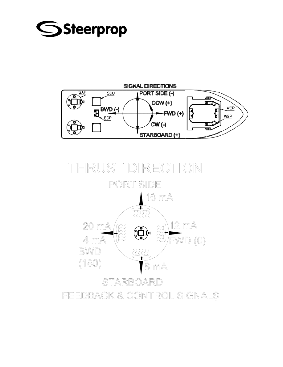
C101566-B Page 47 of 67
26.01.2006
© The information contained in this document is the sole property of Steerprop Ltd. any reproduction or disclosure in part or whole without written permission is prohibited.
DOC-1017-1
15 E
LECTRIC INSTALLATION
15.1 S
IGNAL DIRECTIONS
The 4…20 mA angle feedback transmitter values are increasing CCW. The zero (12
mA) can be set externally.
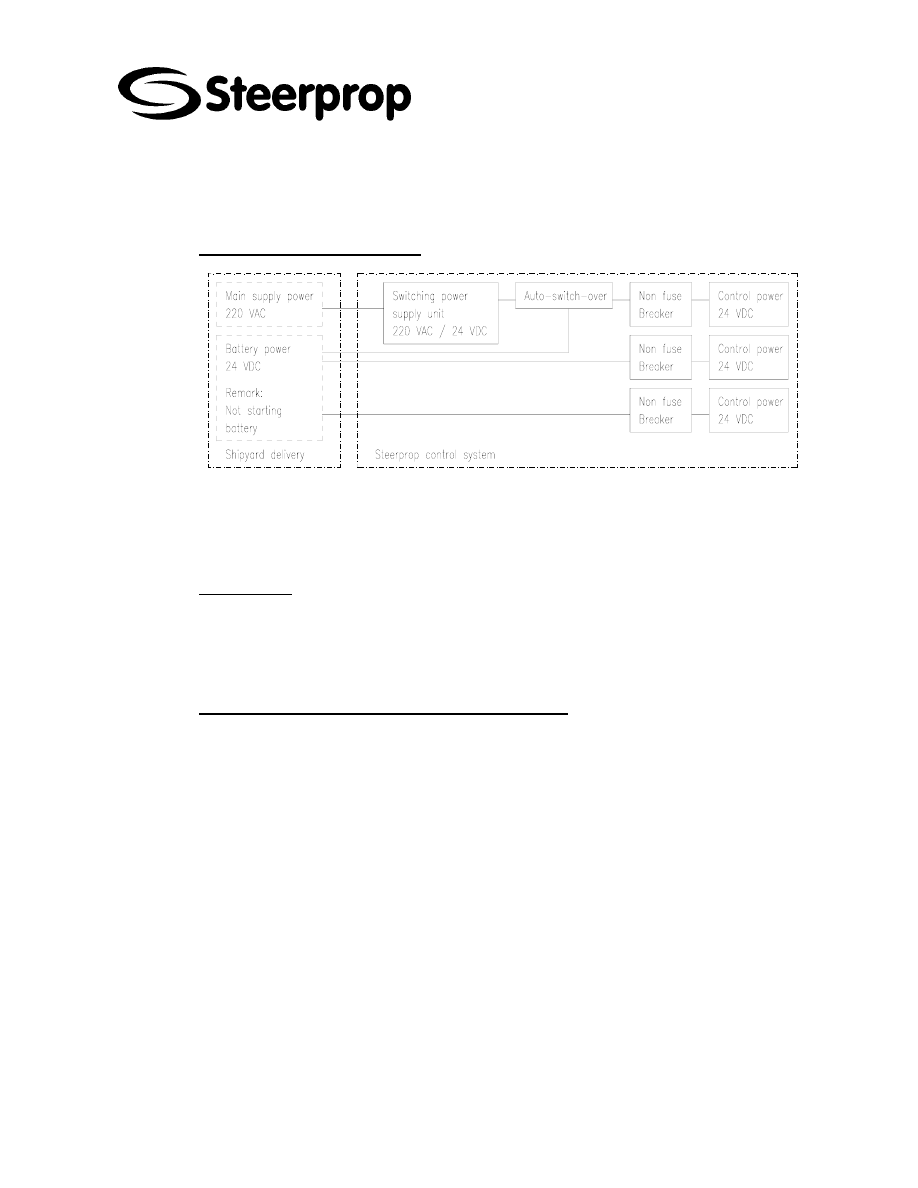
C101566-B Page 48 of 67
26.01.2006
© The information contained in this document is the sole property of Steerprop Ltd. any reproduction or disclosure in part or whole without written permission is prohibited.
DOC-1017-1
15.2 V
OLTAGE SUPPLY
15.2.1 C
ONTROL VOLTAGE SUPPLY
The Steerprop control voltage supply is redundant and straightforward system. The
main control system is supplied from single phase AC network and from a back-up
battery. The indication and back-up control systems are supplied from battery. The
battery should be separate from the engines starting batteries.
15.2.2 AC
SUPPLY
Permanent frequency variations ..........................................± 5 % of nominal
Permanent voltage variations....................................... + 6/- 10 % of nominal
Frequency transients (5 s duration) ...................................± 10 % of nominal
Voltage transients (1,5 s duration) .....................................± 20 % of nominal
15.2.3 24
VDC
SUPPLY FOR ELECTRIC AND CONTROL
15.2.3.1 P
OWER SUPPLY VARIATIONS FOR EQUIPMENT CONNECTED TO
D.C.
SYSTEMS
Voltage tolerance continuous ............................................ 21.6 … 26.4 VDC
Voltage transients cyclic variation .......................................± 5 % of nominal
Voltage ripple ....................................................................± 10 % of nominal
15.2.3.2 P
OWER SUPPLY VARIATIONS FOR EQUIPMENT CONNECTED TO BATTERY POWER
SUPPLY
When using low voltage battery supply, the charging equipment, batteries and cables
are to keep the voltage at equipment terminals within below defined tolerances of the
nominal voltage during charging and discharging. The battery is not allowed to connect
to engine starting systems.
Voltage tolerance .................................................................. 19.2 … 30 VDC
Voltage transients (up to 2 s duration) ..............................± 20 % of nominal
Provisions are to be made for preventing reverse current from the battery through the
charging device.

C101566-B Page 49 of 67
26.01.2006
© The information contained in this document is the sole property of Steerprop Ltd. any reproduction or disclosure in part or whole without written permission is prohibited.
DOC-1017-1
15.2.4 24
VDC
SUPPLY FOR INSTRUMENTS
(
ALARM TRANSDUCERS ETC
.)
15.2.4.1 P
OWER SUPPLY VARIATIONS FOR EQUIPMENT CONNECTED TO
D.C.
SYSTEMS
Voltage tolerance continuous ............................................ 21.6 … 26.4 VDC
Voltage transients cyclic variation .......................................± 5 % of nominal
Voltage ripple ....................................................................± 10 % of nominal
15.2.4.2 P
OWER SUPPLY VARIATIONS FOR EQUIPMENT CONNECTED TO BATTERY POWER
SUPPLY
When using low voltage battery supply, the charging equipment, batteries and cables
are to keep the voltage at equipment terminals within below defined tolerances of the
nominal voltage during charging and discharging. The battery is not allowed to connect
to engine starting systems.
Voltage tolerance .................................................................. 18 … 31.2 VDC
Voltage transients (up to 2 s duration) ..............................± 25 % of nominal
Provisions are to be made for preventing reverse current from the battery through the
charging device.
15.3 L
OCATIONS
15.3.1 C
ONTROL SPACE
Protection class for electric components................................................ IP 22
Ambient temperatures ...............................................+5°C to +45°C (+50°C)
15.3.2 M
ACHINERY SPACE
Protection class for electric components................................................ IP 44
Ambient temperatures ............................................................ +5°C to +55°C
15.3.3 O
UTDOOR SPACE
* Protection class for electric components ............................................. IP 56
* Ambient temperatures ........................................................ -25°C to +55°C
15.4 EMC
COMPATIBILITY FOR CONTROL EQUIPMENTS
To the test of the type approved components and systems has been included the
electromagnetic immunity and emission tests according relevant location of the
component in the vessel. The basic demand for components used at Steerprop control
system is CE-marking.
Also one complete Steerprop control unit has been tested for design verification
purposes.
15.5 E
NVIRONMENT
15.5.1 R
ELATIVE HUMIDITY
Relative humidity up to 95% +/-5 % at all relevant temperatures.

C101566-B Page 50 of 67
26.01.2006
© The information contained in this document is the sole property of Steerprop Ltd. any reproduction or disclosure in part or whole without written permission is prohibited.
DOC-1017-1
15.5.2 S
ALT CONTAMINITY
Salt-contaminated atmosphere up to 1 mg salt per m³ of air, at all relevant
temperatures and humidity conditions.
15.5.3 O
IL
Mist and droplets of fuel and lubricating oil. Oily fingers.
15.5.4 A
CCELERATION
Acceleration caused by the vessel's movement in waves. Peak acceleration ±1,0 g.
Period 5 to 10 seconds.
15.5.5 V
IBRATIONS
Frequency range 3 to 100 Hz.
Amplitude 1 mm (peak value) below 13,2 Hz.
Acceleration amplitude 0,7 g above 13,2 Hz.

C101566-B Page 51 of 67
26.01.2006
© The information contained in this document is the sole property of Steerprop Ltd. any reproduction or disclosure in part or whole without written permission is prohibited.
DOC-1017-1
16 C
ABLING
The total system is completed in the vessel, where the cabling is the important factor in
the EMC means. The cabling procedures are described in Steerprop manual.
16.1 C
ABLE TYPES AND NUMBERS
Cable code consists of three sections A-B-CCC, where A is the number of the
propulsor and B is cable type (table below) and CCC is three digit running number.
Basically smaller cable numbers are always nearer to the propulsor.
SECTION CODE
DESCRIPTION
A
0
Cable connected between propulsors
A
1
Cable belongs to propulsor 1
A
2
Cable belongs to propulsor 2
B A
Alarm
cable
B
AS
Alarm cable, screened, equipped with compact low impedance shield
B C
Control
cable
B
CC
CAN-BUS cable, cores twisted into pairs and pairs into layers and wrapped
with foil. Cable is screened, equipped with compact low impedance shield.
Characteristic impedance 120 Ohm.
B
CP
Control cable, cores twisted into pairs and pairs into layers and wrapped
with foil.Cable is screened, equipped with compact low impedance shield.
B
CS
Control cable, screened, equipped with compact low impedance shield
B
D
Data cable cores twisted into pairs and pairs into layers and wrapped with
foil.Cable is screened, equipped with compact low impedance shield (mainly
for RS 422 or equal).
B
I
Indication cable, can also be BUS cable
B
IC
CAN-BUS cable, cores twisted into pairs and pairs into layers and wrapped
with foil. Cable is screened, equipped with compact low impedance shield.
Characteristic impedance 120 Ohm.
B P
Power
cable
B
PF
Power cable, screened, equipped with compact low impedance shield.
Frequency converter cable. Distance from control and alarm cables 500
mm.
B
PS
Power cable, screened, equipped with compact low impedance shield
C
Running
number

C101566-B Page 52 of 67
26.01.2006
© The information contained in this document is the sole property of Steerprop Ltd. any reproduction or disclosure in part or whole without written permission is prohibited.
DOC-1017-1
16.2 24
VDC
CABLE POWER TABLE
Steerprop cabling list includes for cable calculation power or current information or
even needed cable diameter. Normally in 24 VDC circuits the current is so big, that it
has some influence for cable diameter. The cross section of the cable can be
calculated from known values of power and maximum voltage drop of cable.
For example if the minimum supply for Steerprop Control Unit (SCU) is 24 VDC 10 %
and the minimum voltage of device beyond the cable is 24 VDC 20 % then maximum
voltage drop of cable is 2.4 V.
The cable length is calculated at metres.
Diameter /mm2
Power
W
0,5 1 1,5
2,5 4 6 10 16 25 35
5
165 329 494
823
1317 1975 3291 5266 8229 11520 m
10
82 165 247
411
658 987 1646 2633 4114 5760 m
15
55 110 165
274
439 658 1097 1755 2743 3840 m
20
41 82
123
206
329 494 823 1317
2057
2880 m
25
33 66 99
165
263 395 658 1053
1646
2304 m
30
27 55 82
137
219 329 549 878 1371
1920 m
40
21 41 62
103
165 247 411 658 1029
1440 m
50
16 33 49 82 132 197 329 527 823 1152 m
60
14 27 41 69 110 165 274 439 686 960 m
70
12 24 35 59 94 141 235 376 588 823 m
80
10 21 31 51 82 123 206 329 514 720 m
90
9 18 27 46 73 110 183 293 457 640 m
100
8 16 25 41 66 99 165 263 411 576 m
125
7 13 20 33 53 79 132 211 329 461 m
150
5 11 16 27 44 66 110 176 274 384 m
175
5 9 14 24 38 56 94 150 235 329 m
200
4 8 12 21 33 49 82 132 206 288 m
225
4 7 11 18 29 44 73 117 183 256 m
250
3 7 10 16 26 39 66 105 165 230 m
275
3 6 9
15 24 36 60 96 150
209
m
300
3 5 8
14 22 33 55 88 137
192
m
350
2 5 7
12 19 28 47 75 118
165
m
400
2 4 6
10 16 25 41 66 103
144
m
450
2 4 5 9 15 22 37 59 91 128 m
500
2 3 5 8 13 20 33 53 82 115 m

C101566-B Page 53 of 67
26.01.2006
© The information contained in this document is the sole property of Steerprop Ltd. any reproduction or disclosure in part or whole without written permission is prohibited.
DOC-1017-1
16.3 AWG
DIMENSIONS
AWG DIAMETER AREA
RESISTANCE
NRO MM
MM2
OHM/KM
500 17,96 253
0,07
350 15,03 177
0,10
250 12,70 127
0,14
4/0 11,68 107,2
0,18
3/0 10,40 85,0
0,23
2/0 9,27
67,5
0,29
1/0 8,25
53,5
0,37
1 7,35 42,4
0,47
2 6,54 33,6
0,57
4 5,19 21,2
0,91
6 4,12 13,3
1,44
8 3,26 8,37
2,36
10 2,59 5,26
3,64
12 2,05 3,31
5,41
14 1,63 2,08
8,79
16 1,29 1,31
14,7
18 1,024 0,823
23,0
20 0,813 0,519
34,5
22 0,643 0,324
54,8
24 0,511 0,205
89,2
26 0,405 0,128
146
28 0,320 0,0804 232
30 0,255 0,0507 350
32 0,203 0,0324 578
34 0,160 0,0200 899
36 0,127 0,0127 1426
38 0,102 0,00811 2255
40 0,079 0,00487 3802
42 0,064 0,00317 5842
44 0,051 0,00203 9123
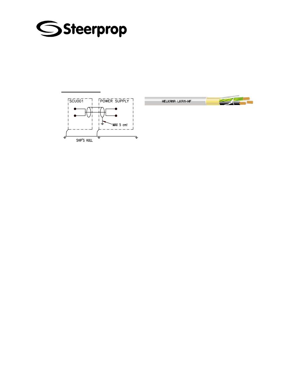
C101566-B Page 54 of 67
26.01.2006
© The information contained in this document is the sole property of Steerprop Ltd. any reproduction or disclosure in part or whole without written permission is prohibited.
DOC-1017-1
16.4 D
ESIGN AND CABLING WORK
The cabling diagrams are purposed for design, selection and installation of the cables
onboard.
16.4.1 P
OWER CABLES
PS TYPE:
The shield is connected at supplying end to the
ship’s hull.
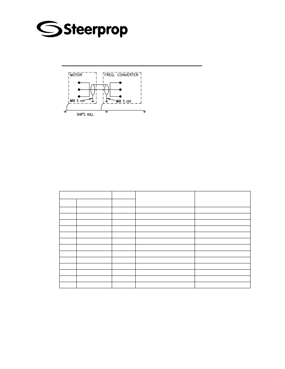
C101566-B Page 55 of 67
26.01.2006
© The information contained in this document is the sole property of Steerprop Ltd. any reproduction or disclosure in part or whole without written permission is prohibited.
DOC-1017-1
16.4.2 F
REQUENCY CONVERTER AND BRAKE RESISTOR CABLING
FREQUENCY CONVERTER
The cable between frequency converter and
motor should be equipped with compact
low-impedance shield and intended for the
specific mains voltage.
Cable marking is
3 + scr
3 = number of wires
Scr = low impedance screen
More detailed instruction from inverter
manufacturers instructions.
BRAKE RESISTOR CABLING
The connection cable to the brake resistor
is to be screened / armoured. Always
connect the screen / armouring in both
ends.
16.4.2.1 F
REQUENCY CONVERTER CABLE SELECTION
FREQUENCY CONVERTER
SUPPLY
SIZE
CURRENT / A
FUSE / A
MAINS AND MOTOR CABLE,
CU TYPE
GROUND CONNECTOR
9
7
10
3*1.5 + 1.5 mm2
2.5 mm2
12
9
16
3*2.5 + 2.5 mm2
2.5 mm2
16
12
20
3*4 + 4 mm2
10 mm2
22
16
25
3*6 + 6 mm2
10 mm2
31
22
35
3*10 + 10 mm2
10 mm2
38
31
50
3*10 + 10 mm2
35 mm2
45
38
50
3*10 + 10 mm2
35 mm2
61
45
63
3*16 + 16 mm2
35 mm2
72
61
80
3*16 + 16 mm2
70 mm2
87
72
100
3*35 + 16 mm2
70 mm2
105
87
125
3*50 + 25 mm2
70 mm2
140
105
160
3*70 + 35 mm2
95 mm2
163
140
200
3*95 + 50 mm2
95 mm2
16.4.2.2 F
EEDBACK CABLE FROM ELECTRIC MOTOR TO FREQUENCY CONVERTER
For encoder cables - the cables should be without splices - one piece from encoder to
drive - shielded, pair twisted cable, shield earthed at both ends - every splice creates a
source of possible interference.
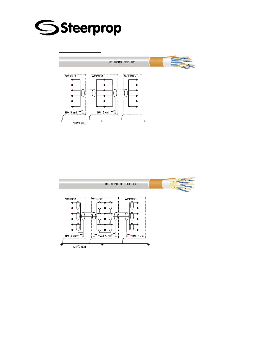
C101566-B Page 56 of 67
26.01.2006
© The information contained in this document is the sole property of Steerprop Ltd. any reproduction or disclosure in part or whole without written permission is prohibited.
DOC-1017-1
16.4.3 C
ONTROL CABLES
Screened cable equipped with compact low-
impedance shield. The shield is connected at
supplying end to the ground.
Normally the control cable minimum
dimensions are given by the society and
sometimes they demand more, than actually
needed.
Our recommendation for analogue control
cables is 0.75 mm2 due the connections.
Cable marking example in the cable list:
4 x 2 + scr
4 = 4 pairs
2 = pair
scr = cable has low impedance screen
So this cable has 4 x 2 = 8 wires
16.4.4 C
ONTROL CABLE WITH TWISTED PAIRS AND SCREEN
This cable type is used normally with
analogue signals. The cable screens are
connected at both ends to ground. The pair
shielding is connected to the ground only at
the supply end. Our recommendation for
analogue control cables is 0.5 mm2 or 0.75
mm2 (recommended) due the connections.
Cable marking example in the cable list:
4 x (2+1) + scr
4 = 4 twisted pairs
2 = pair
+1 = pair shield with ground connector
scr = cable has low impedance screen
So this cable has 4 x 2 = 8 wires
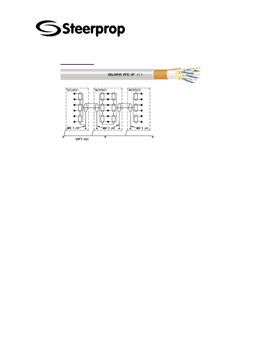
C101566-B Page 57 of 67
26.01.2006
© The information contained in this document is the sole property of Steerprop Ltd. any reproduction or disclosure in part or whole without written permission is prohibited.
DOC-1017-1
16.4.5 D
ATA CABLES
For serial data transmission is this cable
type used. The cable screens are
connected at both ends to ground. The pair
shielding is connected to the ground only at
the supply end. For RS422 cable should the
nominal impedance be ca 110...150 Ohm.
Our recommendation for data control cables
is 0.5 mm2.
Cable marking example in the cable list:
4 x (2+1) + scr
4 = 4 twisted pairs
2 = pair
+1 = pair shield with ground connector
scr = cable has low impedance screen
So this cable has 4 x 2 = 8 wires
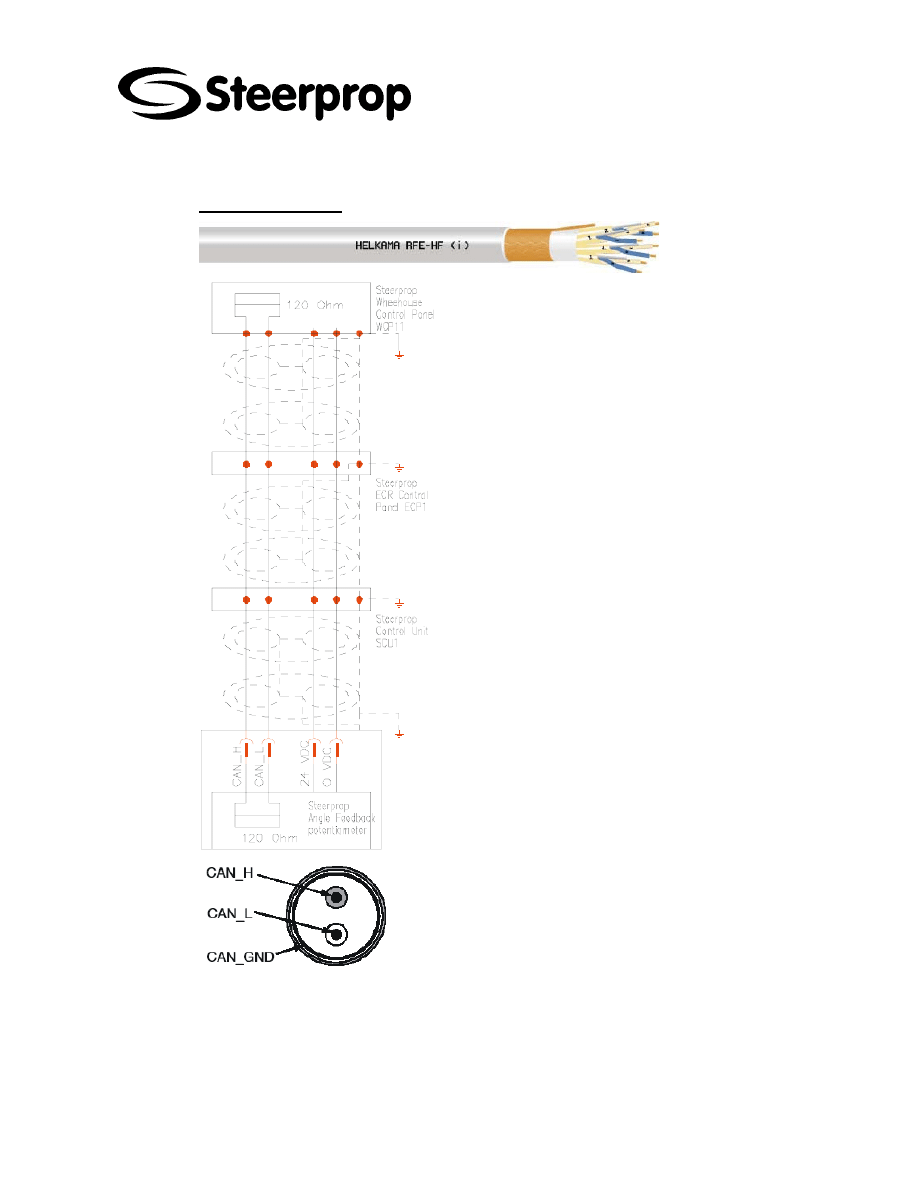
C101566-B Page 58 of 67
26.01.2006
© The information contained in this document is the sole property of Steerprop Ltd. any reproduction or disclosure in part or whole without written permission is prohibited.
DOC-1017-1
16.4.6 CAN
BUS CABLES
CAN (Controller Area Network) was
developed for the networking of
automobiles, but in the meantime being
used more and more in industrial
application. CAN is internationally
standardized according to ISO 11898. The
maximum length for the Bit-rate of 125 kBit
is 500 m used in marine applications.
¾
STRUCTURE RECOMMENDATION
Bare copper wire conductor
Cores twisted into pairs and pairs into
layers
Wrapping of plastic foil
Screen braiding of copper wire
Outer sheath
Peak voltage 250 V
Testing voltage 1500 V
Characteristic impedance 100....150
Ohm
Cable resistance < 40 mOhm/m
Cable diameter 0.5...0.6 mm2 or
AWG20.
¾
CABLE CONNECTION
Steerprop cabling does not have D-sub
connectors. The cables should be
connected to the normal connectors. The
CAN bus cable contains normally 5 wires (if
the voltage supply lines are going with the
same cable). The CAN-L, CAN-H and GnD
Wire start on one end of the total network, a
terminator of 120 Ohm terminator resistor is
connected between CAN-L and CAN-H.
The CAN BUS cable is one line going
through the system, normally without or
short T connections. The star connection is
not allowed. On the other end of the cable
again a resistor of 120 Ohm connected
between the CAN lines. The CAN BUS
cable has special demand of the 120 Ohm
characteristic impedance. The voltage
supply can be a normal control cable with
screen.

C101566-B Page 59 of 67
26.01.2006
© The information contained in this document is the sole property of Steerprop Ltd. any reproduction or disclosure in part or whole without written permission is prohibited.
DOC-1017-1
16.4.6.1 A
PPLICABLE
CAN
BUS CABLES
MAKER CODE
TYPE
SPECIFICATION
U.I.Lapp 2170
266
UNITRONIC
BUS CAN
1x2x0.5
U.I.Lapp 2170
267
UNITRONIC
BUS CAN
2x2x0.5
U.I.Lapp 2170
269
UNITRONIC
BUS CAN
1x2x0.75
U.I.Lapp 2170
270
UNITRONIC
BUS CAN
2x2x0.75
HelkamaBica
DAMA-HF
4x(2+1)x0.5
16.4.7 D
ISTANCE OF DIFFERENT TYPE OF CABLES
Different type of cables should be assembled apart from each other to avoid
electromagnetic interference (EMI). If different type of cables crosses each other there
should be 90 angle between cables.
CABLE TYPE
FROM POWER CABLES
FROM CONTROL CABLES
FROM HIGHLY EMI
GENERATING CABLES
Power cable
O,1 m
O,5 m
Control cable
0,1 m
0,5 m
Highly EMI
generating cable
0,5 m
O,5 m
16.5 I
NSTALLATION AND CONNECTIONS
16.5.1 P
ROTECTION PIPING WORK
If protection pipes or similar are used for cables they
should be assembled so that water and other liquid can
come out from pipe.
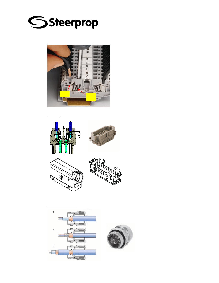
C101566-B Page 60 of 67
26.01.2006
© The information contained in this document is the sole property of Steerprop Ltd. any reproduction or disclosure in part or whole without written permission is prohibited.
DOC-1017-1
16.5.2 W
IRING AND TERMINALS
Bend
here
Hole
The internal wiring is wired-up to terminal strip or
equal. The terminal block for external cabling has
equipped with spring clamp type connection
elements, which are vibration tolerant construction.
It is possible to connect up to four wires to one
terminal except power terminals where are places
for two wires per terminal.
Connect only one wire per spring. To open the
terminal use screwdriver and put it in square hole
and bend it to open the terminal. When terminal is
open put the wire in circle hole and release the
spring by taking screwdriver away from terminal.
16.5.3 P
LUGS
The Steerprop propulsor and its auxiliary
systems like hydraulics are equipped
with Harting type of plugs.
16.5.4 C
ABLE GLANDS
There are no cable glands on electronic units except on
terminal boxes of propulsor and hydraulic power unit for
their internal wiring.
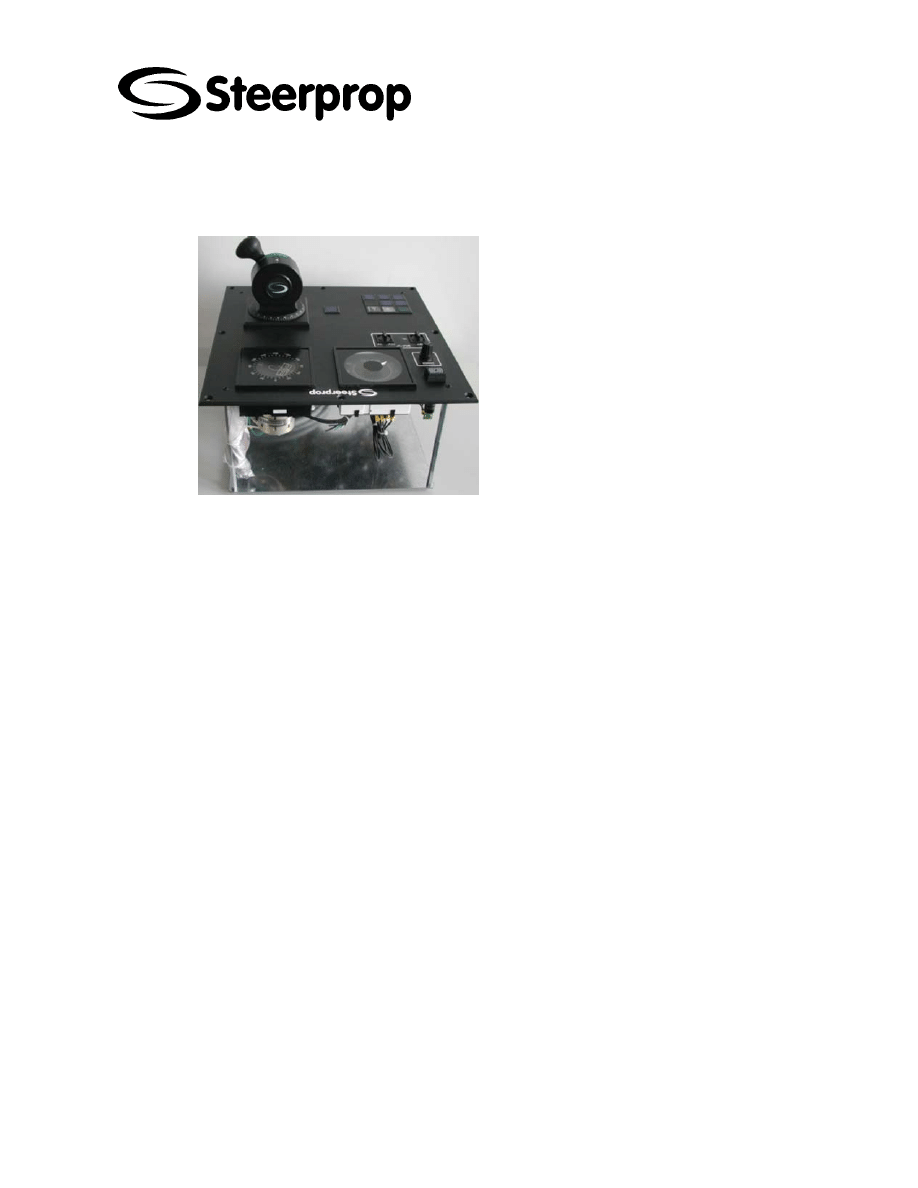
C101566-B Page 61 of 67
26.01.2006
© The information contained in this document is the sole property of Steerprop Ltd. any reproduction or disclosure in part or whole without written permission is prohibited.
DOC-1017-1
17 E
LECTRIC UNIT INSTALLATION
17.1 R
EMOTE CONTROL PANELS
¾
PROTECTION DURING INSTALLATION
Panels should be protected during assembly
work to avoid scratches and damages. Keep
them always in right position (levers, meters,
push buttons up). Do not use them as an
assembly plate or place for tools.
¾
CUTTING THE OPENINGS FOR
CONTROL PANEL TO THE CONTROL
CONSOLE
The dimension drawings include the cut-out
drawing. The panel should be protected under
cutting the hole to the console or panel. You
should be very careful, when you cut wooden
material. There is a risk, that the sawdust can
harm the operation of the control equipments.
¾
CLEANING
After assembly clean all sawdust, plastic dust,
etc. away. Do not use air pressure for cleaning
but some cleaning cloth, which is not getting
fluffy. The pressurized air can take up those
impurities inside of the control equipments.
¾
GROUNDING
The mounting rail must be connected to ground
potential. This is the only way to guarantee that
the integrated surge voltage protection
functions and that the shield of the bus
conductor makes contact effectively.
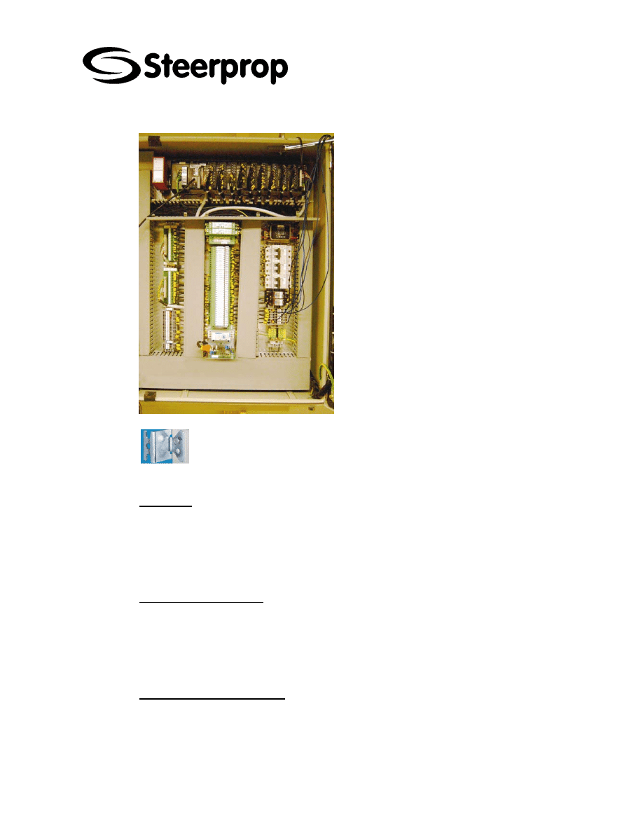
C101566-B Page 62 of 67
26.01.2006
© The information contained in this document is the sole property of Steerprop Ltd. any reproduction or disclosure in part or whole without written permission is prohibited.
DOC-1017-1
17.2 C
ONTROL UNITS
¾
ASSEMBLY DIRECTION
Assembly direction (top and bottom) is shown
on dimension / assembly drawing of unit.
¾
SUPPORT FRAME
When you design the support frame for control
units, take care of that those frames are stabile
and stiff enough to prevent extra vibrations and
shocks.
¾
WALL MOUNTING
Use units wall brackets for mounting the unit on
the wall. Do NOT drill any assembly holes
through units back! In any cases all kind of
drilling and similar work should be avoided
inside the unit. If you should use the internal
assembly holes of the control unit, do not drill
through the control unit. Make the fastening
holes to the bulkhead or equal first and fasten
after that. All units are designed for wall
assembly.
¾
ASSEMBLY BRACKETS
Never use assembly brackets for lifting. Lifting destroys them..
17.2.1 C
OOLING
For cooling there should be some free space around the electronic units. Normally the
dimension drawings of the motor controllers have also reservation for cooling space
around the controller. All heat producing equipments (diesel motors, boilers, etc.)
should be at least 1 m away from units and not under the units. Their cooling air outlet
should not blow against control unit.
17.2.2 V
IBRATION ABSORBER
Vibration absorber should be used if electronic unit is mounted near to machinery or
place where noticeable vibration might occur. Make sure that the mounting base for
unit is steady enough. When you select the vibration absorber, you should be careful,
that those vibration absorbers does not make the vibration amplitude bigger and
destroy the devices.
17.2.3 C
LEANLINESS AND PURITY
Keep always the control unit doors closed when you do not work with it to avoid
impurities to go inside of the control unit. If somebody is working near of the causing
impurities or equal, prevent these impurities go inside of the control units. All filters of
units should be replaced about 3 months after the commissioning
Try to avoid any oil mist to getting inside units. Keep the doors closed and/or put some
protection around the units.
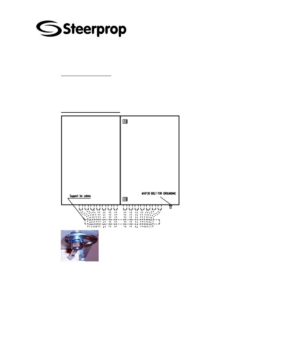
C101566-B Page 63 of 67
26.01.2006
© The information contained in this document is the sole property of Steerprop Ltd. any reproduction or disclosure in part or whole without written permission is prohibited.
DOC-1017-1
To keep the units clean the doors should be closed all the time when there is no work
to do with units. When assembly and connection works have done, all trash should
clean away from units. Use cleaning cloth, which is not getting fluffy.
17.2.4 C
ONDENSED WATER
To avoid condense keep the doors closed during assembly work. Also the temperature
should be steady and warm enough (>15 C). After assembly work when the control
voltage can be connected it is good to keep the voltage on all the time if the condition is
bad. Then the components stay at operating temperature and dry.
17.2.5 C
ONTROL UNIT CABLING
¾
CABLE GLANDS
There are NO cable glands on
electronic units. Cable glands
should be metal and correct size
to get tight connection to cable.
Also it is highly recommend to
use EMC glands where the
cable shield can be connected
to ground through gland.
¾
CABLING DIRECTION
All electronic units are designed
so that cables go to unit trough
bottom. Cables should be
supported near to unit.
¾
GROUNDING
The control units must always be grounded with an grounding conductor
connected to the grounding terminal.
¾
GROUNDING BOLT
All units are equipped with bolt for grounding. The bolt is under the box as
shown at picture.

C101566-B Page 64 of 67
26.01.2006
© The information contained in this document is the sole property of Steerprop Ltd. any reproduction or disclosure in part or whole without written permission is prohibited.
DOC-1017-1
17.3 F
REQUENCY CONVERTER
17.3.1 G
ROUND CONNECTIONS
The frequency converter must always be grounded
with an grounding conductor connected to the
grounding terminal.
The control units must always be grounded with an
grounding conductor connected to the grounding
terminal.
The earth fault protection inside the frequency
converter protects only the converter itself against
earth faults in the motor or the motor cable.
Due to the high capacitive currents present in the
frequency converter, fault current protective
switches may not function properly. If fault current
protective switches are used they must be tested
with the drive with earth fault currents that are
possible to arise in fault situations.
The mounting rail must be connected to ground
potential. This is the only way to guarantee that the
integrated surge voltage protection functions and
that the shield of the bus conductor makes contact
effectively.
¾
GROUNDING BAR
¾
GROUND CONNECTION, SMALLER UUNITS
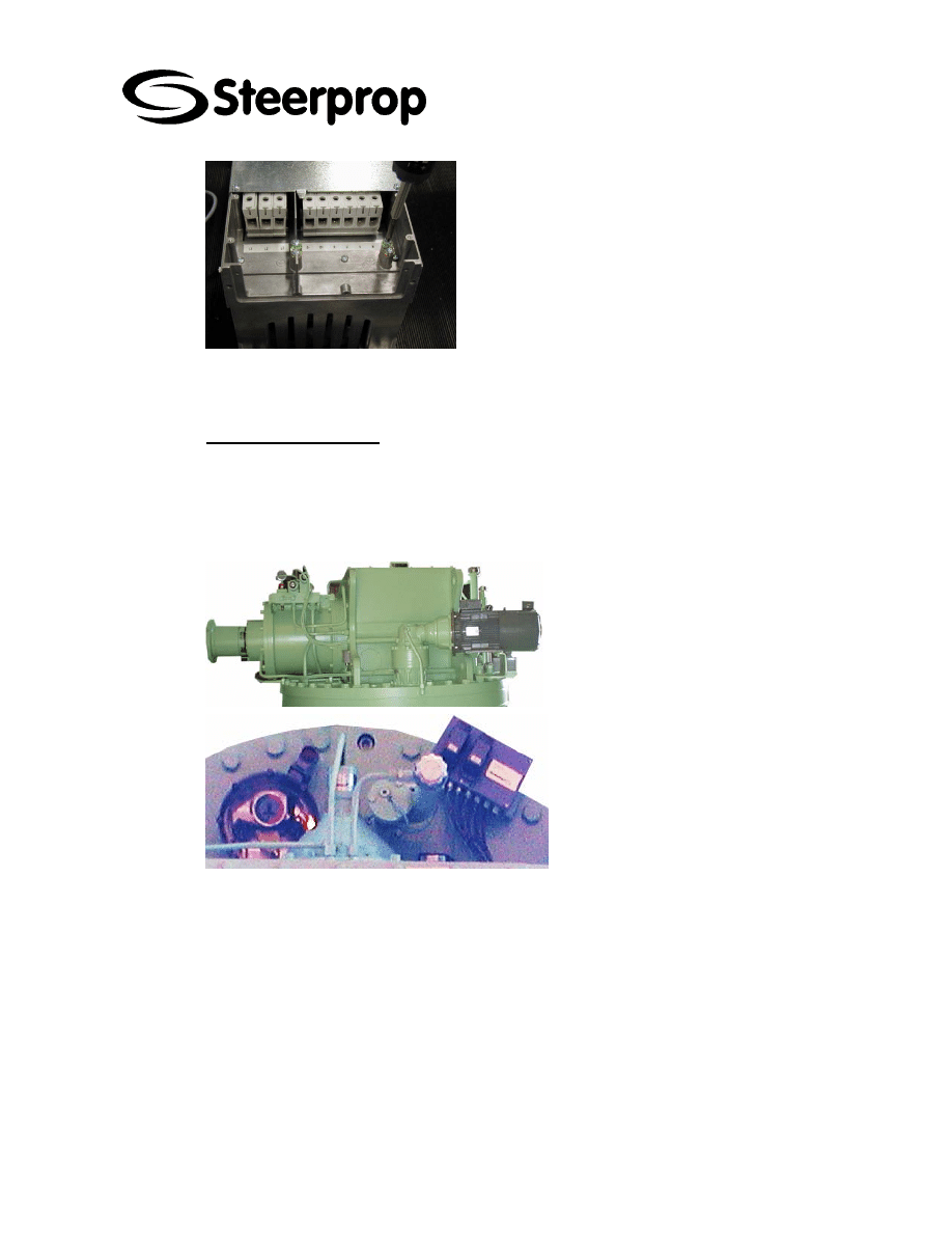
C101566-B Page 65 of 67
26.01.2006
© The information contained in this document is the sole property of Steerprop Ltd. any reproduction or disclosure in part or whole without written permission is prohibited.
DOC-1017-1
¾
GROUND CONNECTOR, BIGGER UNITS
17.3.2 V
IBRATION DAMPERS
We do not usually recommend the use of vibration dampers - they have a tendency to
increase vibration at the resonance frequency. If you want ot use dampers, use as stiff
a damper as possible - a rubber mat or equivalent.
17.4 P
ROPULSOR CABLING
Propulsor internal cabling is made to
connection box. For the external cabling
there is three plug connectors
¾
TRANSMITTER UNIT
for feedback cable is plug XP01
for indicator separate CAN-BUS
cable is plug XP05
¾
STEERPROP CONNECTION BOX
SCB
for alarms and indications is plug
XP02
for clutch control XP03
¾
GROUNDING
The housings of electric steering and
lubrication pumps should be
connected with an grounding
conductor connected to the
grounding terminal.
The propulsor should be connected
with an 25 mm2 grounding conductor
connected to the grounding terminal.
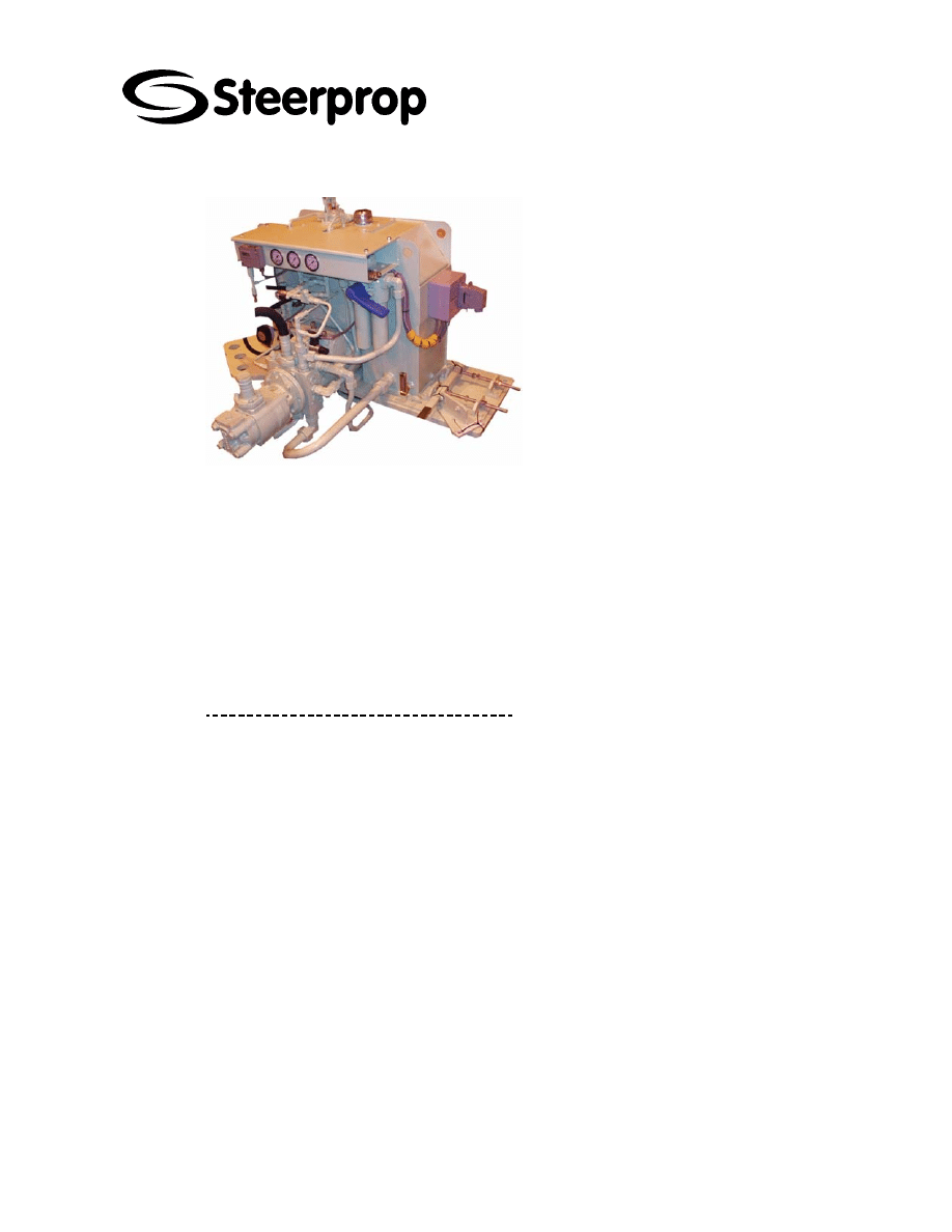
C101566-B Page 66 of 67
26.01.2006
© The information contained in this document is the sole property of Steerprop Ltd. any reproduction or disclosure in part or whole without written permission is prohibited.
DOC-1017-1
17.5 H
YDRAULIC POWER PACK CABLING
for controls and alarms is plug XP04.
17.6 P
OTENTIOMETERS AND SENSITIVE COMPONENTS
Potentiometers shouId be carefully handled by you bearing always in mind that
potentiometer is a kind of precision instrument.
Collision among products, drops onto desks or floor splashing of medicine and water
disclosure of direct rays of the sun and etc. cause breakage of terminal part
deformation of setting part, looseness of binding bands bend of shaft immersion inside
of corruption, raise of housing temperature and etc., which will further incur the second
and third failures and accidents.
b
M
OUNTING
,
R
EMOVING OF
P
OTENTIOMETERS
When wiring after mounted of the panel of potentiometer, we would kindly request you
to take your care of the following matters
into your account.
As for the potentiometers having a pilot part, it is necessary to drill the hole
for the pilot, and mount it without any play.
As for the potentiometers having anti-rotation pin on the panel, it is
necessary to drill the adequate hole for the pin and mount to put it in the
hole. At that time as well as when removing, please do not load over- force
on the housing in order to avoid some causes of failure such as twisting of
the housing, damage of the housing and an idling of the binding band.
In case of the bushing mount type potentiometers, it is absolute necessary
to keep the specified value of the fastening the mounting nut and do not
load over-force on fastening. When fastening with overloaded force, it may
cause a damage of screw thread and an increase of rotating torque.
When mounting the panel by screws, it is absolutely necessary to use the
screws in accordance with those specified in this catalogue, especially the
length of screws. If the length of screws is longer, it may damage the
resistive element inside and if the shorter, it may damage the screw
threads.
When mounting and/or removing a knob, gear, pulley and coupling on the
shaft, please duly take care to avoid over force (over 1 kg) on the shaft.
Especially, when removing, if you use a hammer to make a hitting and
striking, it may cause a failure inside.

C101566-B Page 67 of 67
26.01.2006
© The information contained in this document is the sole property of Steerprop Ltd. any reproduction or disclosure in part or whole without written permission is prohibited.
DOC-1017-1
b
T
ERMINAL WIRING
When wiring to the terminals, please duly note the following matters:
Wiring to the terminals has enough length is reserve and if not, an
excessive force to be caused by vibration, shock and etc. may lead a
damage of terminals part and disconnect inside connections.
When soldering to the terminals, it is absolute necessary to use a soldering
iron with below 60 W (iron part with below the temperature of 350 ºC)
applying within 3 seconds in order to avoid the solder into the housing
body. Moreover, when soldering, the solder may spray and drip and
therefore, please keep your face from such soldering process more than
25cm.
In order to remove the flux of soldering, please do not washing the whole
product and if a wash immerses into the housing, sliding noise and similar
problems may appear, which may make failures.
The strength of terminals is below 1 kgf in directions of pushing, pulling and
bending.
b
C
HECKING
When checking the resistance value of the output terminal of the potentiometer, please
do not use the analogue type ohm-meter but use the digital type ohm-meter.
When the wiper position sets near the ends, the analogue type ohm-meter may be
burnt out the resistive element and wiper.
When checking the insulation resistance di-electric strength with high voltage, please
duly note to do so in case of motor-potentiometer and components with a circuit board.
The motor we use has a withstand voltage of 100V and with a terminal of “GND” has a
setting the earth to the housing, of which facts please take into your account.
Wyszukiwarka
Podobne podstrony:
instalacja debiana
INSTALACJE TRYSKACZOWE I ZRASZACZOWE
Urządzenia i instalacje elektryczne w przestrzeniach zagrożonych wybuchem
Instalacje elektroenergetObl1
Projekt Instalacji deponowanie 2
Instalacje odgromowe
Wybrane elementy automatyki instalacyjnej
instalacje grzewczaet
monter instalacji gazowych 713[07] z2 03 u
8 Instalacja spalin wylotowych id
Installation instructions
ARTICLE SUSPENSION STRUT FRONT REPLACE INSTALL
Instalacja urządzeń grzewczych i wymienników ciepła
04 instalacja
więcej podobnych podstron