
ArcTechDig_P_R23 04.07.00 en
1 of 68
SOFTWARE
KR C...
ArcTechDigital 2.3
for power sources with program number control
Configuration
for KUKA.KR C 5.2, 5.3, 5.4, 5.5
Issued: 11 April 2006
Version: 00

2 of 68
ArcTechDig_P_R23 04.07.00 en
e
Copyright
KUKA Roboter GmbH
This documentation or excerpts therefrom may not be reproduced or disclosed to third parties without the express permission of the publishers.
Other functions not described in this documentation may be operable in the controller. The user has no claim to these functions, however, in
the case of a replacement or service work.
We have checked the content of this documentation for conformity with the hardware and software described. Nevertheless, discrepancies
cannot be precluded, for which reason we are not able to guarantee total conformity. The information in this documentation is checked on a
regular basis, however, and necessary corrections will be incorporated in subsequent editions.
Subject to technical alterations without an effect on the function.
PD Interleaf

3 of 68
ArcTechDig_P_R23 04.07.00 en
Contents
1
General
7
. . . . . . . . . . . . . . . . . . . . . . . . . . . . . . . . . . . . . . . . . . . . . . . . . . . . . . . . .
1.1
System requirements, Installation
8
. . . . . . . . . . . . . . . . . . . . . . . . . . . . . . . . . . . . . . . . . . . . . . . .
1.2
Overview of the configurable options
9
. . . . . . . . . . . . . . . . . . . . . . . . . . . . . . . . . . . . . . . . . . . . .
2
Description of the “ArcTechDigital” commands
11
. . . . . . . . . . . . . . . . . . . .
2.1
General
11
. . . . . . . . . . . . . . . . . . . . . . . . . . . . . . . . . . . . . . . . . . . . . . . . . . . . . . . . . . . . . . . . . . . . . . .
2.1.1
Keyswitch for program execution without welding
11
. . . . . . . . . . . . . . . . . . . . . . . . . . . . . . . . . . .
2.1.2
Program run mode “GO”
11
. . . . . . . . . . . . . . . . . . . . . . . . . . . . . . . . . . . . . . . . . . . . . . . . . . . . . . . .
2.1.3
Switching on the welding process
11
. . . . . . . . . . . . . . . . . . . . . . . . . . . . . . . . . . . . . . . . . . . . . . . .
2.2
Start welding -- ARC ON
11
. . . . . . . . . . . . . . . . . . . . . . . . . . . . . . . . . . . . . . . . . . . . . . . . . . . . . . . .
2.2.1
Schematic sequence diagram ARC ON
12
. . . . . . . . . . . . . . . . . . . . . . . . . . . . . . . . . . . . . . . . . . .
2.2.2
Signal diagram ARC_ON and ARC_SWI
13
. . . . . . . . . . . . . . . . . . . . . . . . . . . . . . . . . . . . . . . . . .
2.3
Welding and ending seams -- ARC OFF
13
. . . . . . . . . . . . . . . . . . . . . . . . . . . . . . . . . . . . . . . . . . .
2.3.1
Schematic sequence diagram ARC OFF
14
. . . . . . . . . . . . . . . . . . . . . . . . . . . . . . . . . . . . . . . . . .
2.3.2
Signal diagram ARC_OFF
15
. . . . . . . . . . . . . . . . . . . . . . . . . . . . . . . . . . . . . . . . . . . . . . . . . . . . . .
2.4
Welding a seam in several sections -- ARC SWITCH
15
. . . . . . . . . . . . . . . . . . . . . . . . . . . . . . . .
2.4.1
Schematic sequence diagram ARC SWITCH
16
. . . . . . . . . . . . . . . . . . . . . . . . . . . . . . . . . . . . . .
2.4.2
Signal diagram ARC_SWI
17
. . . . . . . . . . . . . . . . . . . . . . . . . . . . . . . . . . . . . . . . . . . . . . . . . . . . . . .
3
Programs of the ArcTechDigital package
19
. . . . . . . . . . . . . . . . . . . . . . . . . .
3.1
Program structure
19
. . . . . . . . . . . . . . . . . . . . . . . . . . . . . . . . . . . . . . . . . . . . . . . . . . . . . . . . . . . . . .
3.2
Overview of the “ArcTechDigital” files
20
. . . . . . . . . . . . . . . . . . . . . . . . . . . . . . . . . . . . . . . . . . . . .
4
ArcTechDigital -- basic settings
23
. . . . . . . . . . . . . . . . . . . . . . . . . . . . . . . . . . .
4.1
Activating the ARC 20 option
23
. . . . . . . . . . . . . . . . . . . . . . . . . . . . . . . . . . . . . . . . . . . . . . . . . . . .
4.2
Minimum configuration for power source interface
23
. . . . . . . . . . . . . . . . . . . . . . . . . . . . . . . . . .
4.3
Minimum configuration for program number control
25
. . . . . . . . . . . . . . . . . . . . . . . . . . . . . . . . .
4.3.1
Meaning of the variables
28
. . . . . . . . . . . . . . . . . . . . . . . . . . . . . . . . . . . . . . . . . . . . . . . . . . . . . . . .
5
Principles of the definable signal table
29
. . . . . . . . . . . . . . . . . . . . . . . . . . . .
5.1
Overview, definition
29
. . . . . . . . . . . . . . . . . . . . . . . . . . . . . . . . . . . . . . . . . . . . . . . . . . . . . . . . . . . .
5.1.1
Index tables for configuring physical outputs and inputs
29
. . . . . . . . . . . . . . . . . . . . . . . . . . . . .
5.1.2
Signal tables for digital outputs and inputs
29
. . . . . . . . . . . . . . . . . . . . . . . . . . . . . . . . . . . . . . . . .
5.2
Digital outputs
30
. . . . . . . . . . . . . . . . . . . . . . . . . . . . . . . . . . . . . . . . . . . . . . . . . . . . . . . . . . . . . . . . .
5.2.1
Index table for physical digital outputs
30
. . . . . . . . . . . . . . . . . . . . . . . . . . . . . . . . . . . . . . . . . . . .
5.2.2
Signal tables for digital outputs
31
. . . . . . . . . . . . . . . . . . . . . . . . . . . . . . . . . . . . . . . . . . . . . . . . . . .
5.2.2.1 Definition of the signal states
31
. . . . . . . . . . . . . . . . . . . . . . . . . . . . . . . . . . . . . . . . . . . . . . . . . . . .
5.3
Digital inputs
32
. . . . . . . . . . . . . . . . . . . . . . . . . . . . . . . . . . . . . . . . . . . . . . . . . . . . . . . . . . . . . . . . . .
5.3.1
Index table for physical digital inputs
32
. . . . . . . . . . . . . . . . . . . . . . . . . . . . . . . . . . . . . . . . . . . . . .
5.3.2
Signal tables for digital inputs
33
. . . . . . . . . . . . . . . . . . . . . . . . . . . . . . . . . . . . . . . . . . . . . . . . . . . .
6
Assignment of the signal grouping in normal operation
35
. . . . . . . . . . . .
6.1
Assignment of the outputs
35
. . . . . . . . . . . . . . . . . . . . . . . . . . . . . . . . . . . . . . . . . . . . . . . . . . . . . . .

ArcTechDigital 2.3
4 of 68
ArcTechDig_P_R23 04.07.00 en
6.1.1
Output group O_WELD_START [ ]
35
. . . . . . . . . . . . . . . . . . . . . . . . . . . . . . . . . . . . . . . . . . . . . . .
6.1.2
Output group O_ACK_START [ ]
36
. . . . . . . . . . . . . . . . . . . . . . . . . . . . . . . . . . . . . . . . . . . . . . . . .
6.1.3
Output group O_STROB_PGNO [ ]
37
. . . . . . . . . . . . . . . . . . . . . . . . . . . . . . . . . . . . . . . . . . . . . . .
6.1.4
Output group O_SEAM_END [ ]
37
. . . . . . . . . . . . . . . . . . . . . . . . . . . . . . . . . . . . . . . . . . . . . . . . .
6.1.5
Output group O_ACK_WELD_E[ ]
38
. . . . . . . . . . . . . . . . . . . . . . . . . . . . . . . . . . . . . . . . . . . . . . . .
6.2
Signal output groups for fault service function
39
. . . . . . . . . . . . . . . . . . . . . . . . . . . . . . . . . . . . . .
6.2.1
Output group O_FLT_ARC_ON [ ]
39
. . . . . . . . . . . . . . . . . . . . . . . . . . . . . . . . . . . . . . . . . . . . . . . .
6.2.2
Output group O_FLT_WELD [ ]
40
. . . . . . . . . . . . . . . . . . . . . . . . . . . . . . . . . . . . . . . . . . . . . . . . . .
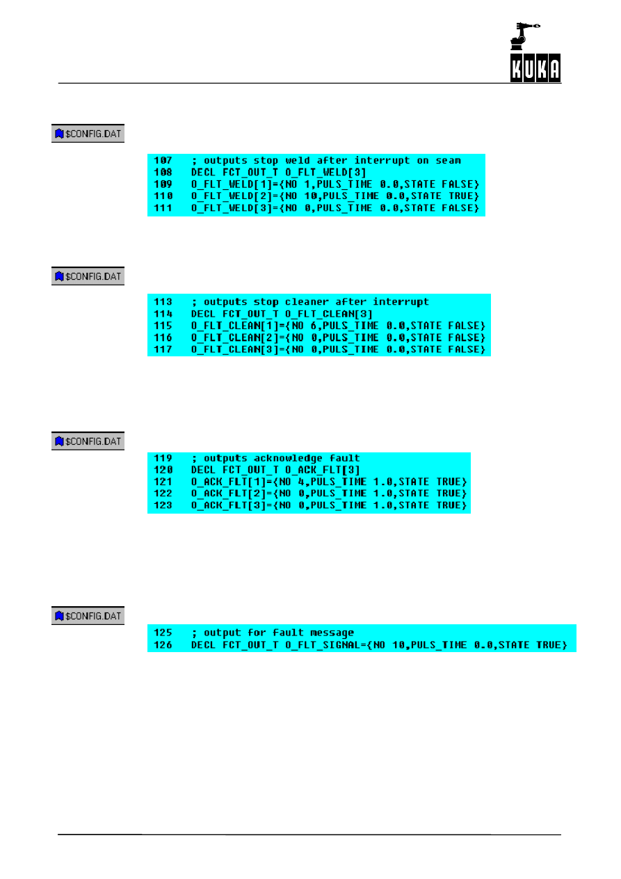
6.2.3
Output group O_FLT_CLEAN [ ]
41
. . . . . . . . . . . . . . . . . . . . . . . . . . . . . . . . . . . . . . . . . . . . . . . . .
6.2.4
Output group O_ACK_FLT [ ]
41
. . . . . . . . . . . . . . . . . . . . . . . . . . . . . . . . . . . . . . . . . . . . . . . . . . . .
6.3
Assignment of the inputs
42
. . . . . . . . . . . . . . . . . . . . . . . . . . . . . . . . . . . . . . . . . . . . . . . . . . . . . . . .
6.3.1
Input group I_WELD_COND [ ]
42
. . . . . . . . . . . . . . . . . . . . . . . . . . . . . . . . . . . . . . . . . . . . . . . . . .
6.3.2
Input group I_START_MOVE [ ]
43
. . . . . . . . . . . . . . . . . . . . . . . . . . . . . . . . . . . . . . . . . . . . . . . . . .
6.3.3
Input group I_WELD_END [ ]
43
. . . . . . . . . . . . . . . . . . . . . . . . . . . . . . . . . . . . . . . . . . . . . . . . . . . .
6.3.4
Input group I_WELD_FLT [ ]
44
. . . . . . . . . . . . . . . . . . . . . . . . . . . . . . . . . . . . . . . . . . . . . . . . . . . . .
6.3.5
Polling of the external keyswitch (Hot/Cold)
45
. . . . . . . . . . . . . . . . . . . . . . . . . . . . . . . . . . . . . . . .
6.3.6
Time_out when polling the inputs
45
. . . . . . . . . . . . . . . . . . . . . . . . . . . . . . . . . . . . . . . . . . . . . . . . .
7
Options for program number specification
47
. . . . . . . . . . . . . . . . . . . . . . . . .
7.1
Signal flow of the program numbers
47
. . . . . . . . . . . . . . . . . . . . . . . . . . . . . . . . . . . . . . . . . . . . . .
7.2
Setting -- parity bit
47
. . . . . . . . . . . . . . . . . . . . . . . . . . . . . . . . . . . . . . . . . . . . . . . . . . . . . . . . . . . . . .
7.3
Timing diagram – program number interface (a)
48
. . . . . . . . . . . . . . . . . . . . . . . . . . . . . . . . . . . .
8
Setting the restart options
49
. . . . . . . . . . . . . . . . . . . . . . . . . . . . . . . . . . . . . . . .
8.1
RESTART_OPTION
49
. . . . . . . . . . . . . . . . . . . . . . . . . . . . . . . . . . . . . . . . . . . . . . . . . . . . . . . . . . . .
8.1.1
Reaction to interpreter stop (STOP key)
49
. . . . . . . . . . . . . . . . . . . . . . . . . . . . . . . . . . . . . . . . . . .
8.2
Configuration in event of ignition faults
50
. . . . . . . . . . . . . . . . . . . . . . . . . . . . . . . . . . . . . . . . . . . .
8.2.1
Ignition repetition monitoring
50
. . . . . . . . . . . . . . . . . . . . . . . . . . . . . . . . . . . . . . . . . . . . . . . . . . . . .
8.3
Ignition fault message suppression option
50
. . . . . . . . . . . . . . . . . . . . . . . . . . . . . . . . . . . . . . . . .
9
Enumeration of the signal groups for fault service functions
51
. . . . . . . .
9.1
Types of faults and causes
51
. . . . . . . . . . . . . . . . . . . . . . . . . . . . . . . . . . . . . . . . . . . . . . . . . . . . . .
9.2
Ignition faults
51
. . . . . . . . . . . . . . . . . . . . . . . . . . . . . . . . . . . . . . . . . . . . . . . . . . . . . . . . . . . . . . . . . .
9.2.1
Signal output group O_FLT_ARC_ON[ ]
51
. . . . . . . . . . . . . . . . . . . . . . . . . . . . . . . . . . . . . . . . . . .
9.3
Welding faults and robot faults
51
. . . . . . . . . . . . . . . . . . . . . . . . . . . . . . . . . . . . . . . . . . . . . . . . . . .
9.3.1
Reaction to robot faults, EMERGENCY STOP and DRIVES OFF
51
. . . . . . . . . . . . . . . . . . . . .
9.3.2
Signal output group O_FLT_WELD[ ]
52
. . . . . . . . . . . . . . . . . . . . . . . . . . . . . . . . . . . . . . . . . . . . .
9.3.3
Signal output group O_FLT_CLEAN[ ]
52
. . . . . . . . . . . . . . . . . . . . . . . . . . . . . . . . . . . . . . . . . . . .
9.3.4
Signal output group O_ACK_FLT [ ]
52
. . . . . . . . . . . . . . . . . . . . . . . . . . . . . . . . . . . . . . . . . . . . . .
9.3.5
Signal O_FLT_SIGNAL
52
. . . . . . . . . . . . . . . . . . . . . . . . . . . . . . . . . . . . . . . . . . . . . . . . . . . . . . . . .
9.3.6
Signal APPL_RUN
53
. . . . . . . . . . . . . . . . . . . . . . . . . . . . . . . . . . . . . . . . . . . . . . . . . . . . . . . . . . . . .
9.4
Special feature IR_STOPMESS program
53
. . . . . . . . . . . . . . . . . . . . . . . . . . . . . . . . . . . . . . . . . .
9.4.1
Joint activation/deactivation routines
53
. . . . . . . . . . . . . . . . . . . . . . . . . . . . . . . . . . . . . . . . . . . . . .
9.5
Configurable fault service functions
54
. . . . . . . . . . . . . . . . . . . . . . . . . . . . . . . . . . . . . . . . . . . . . . .
9.5.1
Fault service functions defined by the user
54
. . . . . . . . . . . . . . . . . . . . . . . . . . . . . . . . . . . . . . . .
10
Further options
55
. . . . . . . . . . . . . . . . . . . . . . . . . . . . . . . . . . . . . . . . . . . . . . . . . .
10.1
Program test in manual mode
55
. . . . . . . . . . . . . . . . . . . . . . . . . . . . . . . . . . . . . . . . . . . . . . . . . . .

5 of 68
ArcTechDig_P_R23 04.07.00 en
10.2
Ignition fault message suppression option
55
. . . . . . . . . . . . . . . . . . . . . . . . . . . . . . . . . . . . . . . . .
10.3
Seam monitoring delay option
55
. . . . . . . . . . . . . . . . . . . . . . . . . . . . . . . . . . . . . . . . . . . . . . . . . . .
11
Mechanical weaving
56
. . . . . . . . . . . . . . . . . . . . . . . . . . . . . . . . . . . . . . . . . . . . . .
11.1
Block selection response
56
. . . . . . . . . . . . . . . . . . . . . . . . . . . . . . . . . . . . . . . . . . . . . . . . . . . . . . . .
11.2
Weave patterns
57
. . . . . . . . . . . . . . . . . . . . . . . . . . . . . . . . . . . . . . . . . . . . . . . . . . . . . . . . . . . . . . . .
11.2.1
Two--dimensional weaving
59
. . . . . . . . . . . . . . . . . . . . . . . . . . . . . . . . . . . . . . . . . . . . . . . . . . . . . .
11.2.2
Creating the “Spiral” weave pattern
59
. . . . . . . . . . . . . . . . . . . . . . . . . . . . . . . . . . . . . . . . . . . . . . .
11.2.3
“Figure--of--eight” weave pattern
61
. . . . . . . . . . . . . . . . . . . . . . . . . . . . . . . . . . . . . . . . . . . . . . . . .
11.2.4
Changing and creating patterns for mechanical weaving
62
. . . . . . . . . . . . . . . . . . . . . . . . . . . . .
11.2.4.1 Changing existing weave patterns
62
. . . . . . . . . . . . . . . . . . . . . . . . . . . . . . . . . . . . . . . . . . . . . . . .
11.2.4.2 Creating your own weave patterns
63
. . . . . . . . . . . . . . . . . . . . . . . . . . . . . . . . . . . . . . . . . . . . . . .
11.2.5
Notes on mechanical weaving
64
. . . . . . . . . . . . . . . . . . . . . . . . . . . . . . . . . . . . . . . . . . . . . . . . . . .
12
Error messages / troubleshooting
65
. . . . . . . . . . . . . . . . . . . . . . . . . . . . . . . . .
12.1
Message groups
65
. . . . . . . . . . . . . . . . . . . . . . . . . . . . . . . . . . . . . . . . . . . . . . . . . . . . . . . . . . . . . . .
12.2
Message time
65
. . . . . . . . . . . . . . . . . . . . . . . . . . . . . . . . . . . . . . . . . . . . . . . . . . . . . . . . . . . . . . . . .
12.3
Message number
65
. . . . . . . . . . . . . . . . . . . . . . . . . . . . . . . . . . . . . . . . . . . . . . . . . . . . . . . . . . . . . .
12.4
Originator
66
. . . . . . . . . . . . . . . . . . . . . . . . . . . . . . . . . . . . . . . . . . . . . . . . . . . . . . . . . . . . . . . . . . . . .
12.5
Message text
66
. . . . . . . . . . . . . . . . . . . . . . . . . . . . . . . . . . . . . . . . . . . . . . . . . . . . . . . . . . . . . . . . . .
12.6
List of error messages
66
. . . . . . . . . . . . . . . . . . . . . . . . . . . . . . . . . . . . . . . . . . . . . . . . . . . . . . . . . .

ArcTechDigital 2.3
6 of 68
ArcTechDig_P_R23 04.07.00 en

1
General
7 of 68
ArcTechDig_P_R23 04.07.00 en
1
General
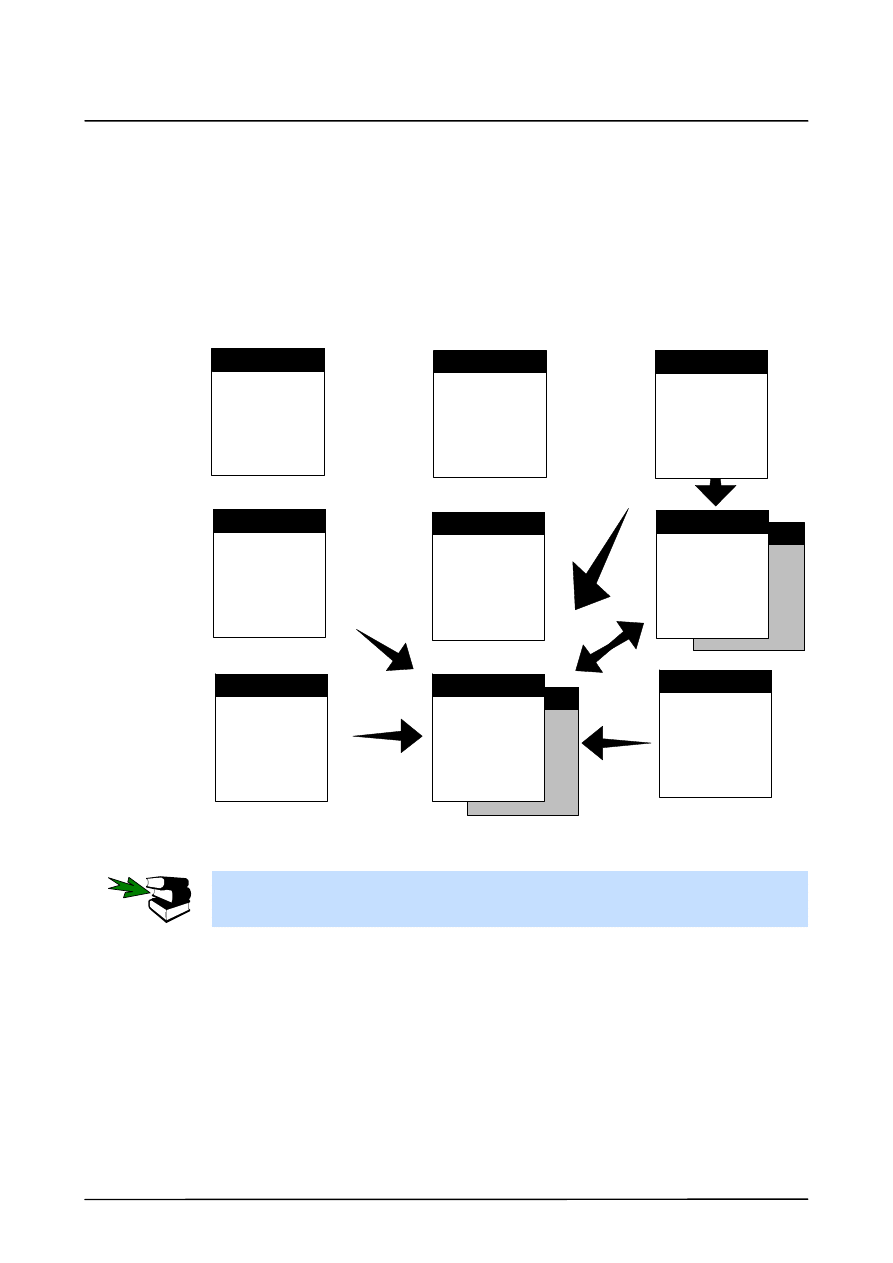
In the development of a welding robot that is easy and safe to use, top priority was given to
the optimized adaptation of the operator interface and the interfacing capability to welding
equipment with program number control, as well as uncomplicated handling of the
ArcTechDigital technology package.
This is intended to allow the trouble--free operation, parameter and hardware configuration
and programming of arc welding applications. The entire range of KRL commands are
available to you at the expert level. Configuration requires sufficient knowledge of the KRL
programming language.
ArcTechDigital features:
G
Menu--guided creation of programs at the user level.
G
Simple operation using application--specific softkeys and menus.
G
Prepared programs and subroutines.
G
Adaptation to the peripheral equipment and configurable options of the digital outputs.
G
Simple setting of variables, entries in files and parameter lists.
G
Use of the function generators for two--dimensional mechanical weaving as well as the
possibility of configuring your own weave patterns.
G
Adaptation to various welding controllers with program number control and their diffe-
rent coding systems.
G
Various routines used for ignition faults and monitoring of the number of ignition at-
tempts.
G
Restart options in case of faults.
This documentation has been created as a supplement to the documentation [Arc Welding,
ArcTechDigital -- Operation] for the user group Expert. In addition to fundamental
descriptions accompanied by schematic sequence diagrams and screenshots of application
tests, information on standard routines as well as specific “ArcTechDigital” applications have
also been provided. This is intended to make parameter and hardware configuration and the
programming of arc welding applications easier.
In the development of a welding robot that is easy and safe to use, top priority was given to
the optimized adaptation of the operator interface and the interfacing capability to welding
equipment with program number control, as well as uncomplicated handling of the
“ArcTechDigital” technology package.
The entire range of KRL commands are available to you at the expert level. This requires
sufficient knowledge of the KRL programming language.
The “ARC Tech 20” commands “ARC ON”, “ARC OFF” and “ARC SWITCH” are described
in Chapter 2. Among other things, information is provided on variable settings, entries
required in files, and parameter lists.
Chapter 3 provides information on the programs and files contained in the ArcTechDigital
package. Information and notes on “ArcTechDigital”--specific basic settings are provided in
Chapter 4.
Chapter 5 explains adaptation to the peripheral equipment. The configuration of the digital
input and output groups is dealt with in Chapter 6.
The transfer of program numbers is explained in Chapter 7. Chapter 8 contains information
on the restart options.
Chapter 9 finally deals with fault situations and fault service functions. Types of faults that
can occur during the ignition and welding processes, their possible causes and appropriate
corrective measures are described.
Further ArcTechDigital settings can be found in Chapter 10.
ArcTechDigital 2.3
8 of 68
ArcTechDig_P_R23 04.07.00 en
The mechanical weaving option included in the “ArcTechDigital” technology package is
described in Chapter 11. There you will find fundamental information on the mode of
operation of the function generators, two--dimensional mechanical weaving, and the
configuration of weave patterns. Examples are used to show you how to change existing
patterns and how to create your own patterns.
Chapter 12 contains a list of error messages along with their causes, effects and remedial
action.
1.1
System requirements, Installation
The Software ArcTechDigital can be used with the following KRC--Software:
-- KR C2, KR C2ed05
-- Software Rel. 5.2, 5.3, 5.4, 5.5
From system software version 5.1 onwards, technology packages are offered
exclusively as ad--on software modules. These are available on CD--ROM.
The installation, uninstallation, reinstallation and update of technology packages
are described in detail in the documentation
[Installation/Uninstallation/Update of Tech Packages].

1
General (continued)
9 of 68
ArcTechDig_P_R23 04.07.00 en
1.2
Overview of the configurable options
The ArcTechDigital technology package also provides a range of options in addition to the
basic configuration:
G
Adaptation to various welding controllers with program number control and their different
coding systems.
G
Various routines used for ignition faults and monitoring of the number of ignition attempts.
G
Re--ignition after faults.
G
Restart options in case of faults in the seam.
G
Configurable user--specific strategies and routines in case of faults.
G
Selection of several defined patterns for mechanical weaving as well as the possibility of
programming your own weave patterns.
Most options are stored in variables that are defined in the files “$CONFIG.DAT” and
“A20.DAT”.
Fundamental information on operator control as well as the menu--guided creation of
programs at user level is provided in the documentation [Arc Welding, ArcTechDigital --
Operation].

ArcTechDigital 2.3
10 of 68
ArcTechDig_P_R23 04.07.00 en
2
Description of the “ArcTechDigital” commands
11 of 68
ArcTechDig_P_R23 04.07.00 en
2
Description of the “ArcTechDigital” commands
2.1
General
The general ArcTechDigital commands are described in this chapter. Softkey assignments
and their meaning. Explanations of the main terms ARC ON, ARC SWI and ARC OFF with
sequence diagrams and signal diagrams.
2.1.1
Keyswitch for program execution without welding
If the keyswitch function has been configured, the appropriate status must be active
(“I_ENB_W_EXT.STATE” TRUE or FALSE according to the configuration). Otherwise weld-
ing is not possible.
2.1.2
Program run mode “GO”
Welding is only possible in the program run mode “GO”. “MSTEP” and “ISTEP” do not allow
the program to run properly. More detailed information on selecting program run modes can
be found in the chapter [Executing and stopping programs].
2.1.3
Switching on the welding process
After the computer runs up, (hot) welding is always deactivated, as is indicated by the welding
torch being struck through on the left--hand status key bar. In order to be able to weld, this
status key must be switched to the “HOT” position corresponding to the symbol shown on
the left.
2.2
Start welding -- ARC ON
The command “ARC ON” contains the parameters for moving the welding torch (type of
motion, velocity, etc.) from the home position to the start point of the seam, the start
parameters (start delay) and the program number.
While the “ARC ON” program phase is being executed, the system scans the peripheral
signal “I_WELD_COND” to check whether the welding controller is ready. When the welding
torch reaches the ignition position, arc ignition is enabled by means of the signal
“O_WELD_START[ ]”.
When the arc has been struck, the welding power source supplies the signal
“I_START_MOVE[ ]”, as a result of which the robot starts to move in accordance with the
programmed path and velocity. The signal “O_ACK_START[ ]” informs the welding controller
that the robot is moving.
The movement from the home position to the start point of the seam can be executed as a
“PTP”, “LIN” or “CIRC” motion.
Approximation is not possible for ARC ON; the torch is stopped exactly at the start of
the seam.
ArcTechDigital 2.3
12 of 68
ArcTechDig_P_R23 04.07.00 en
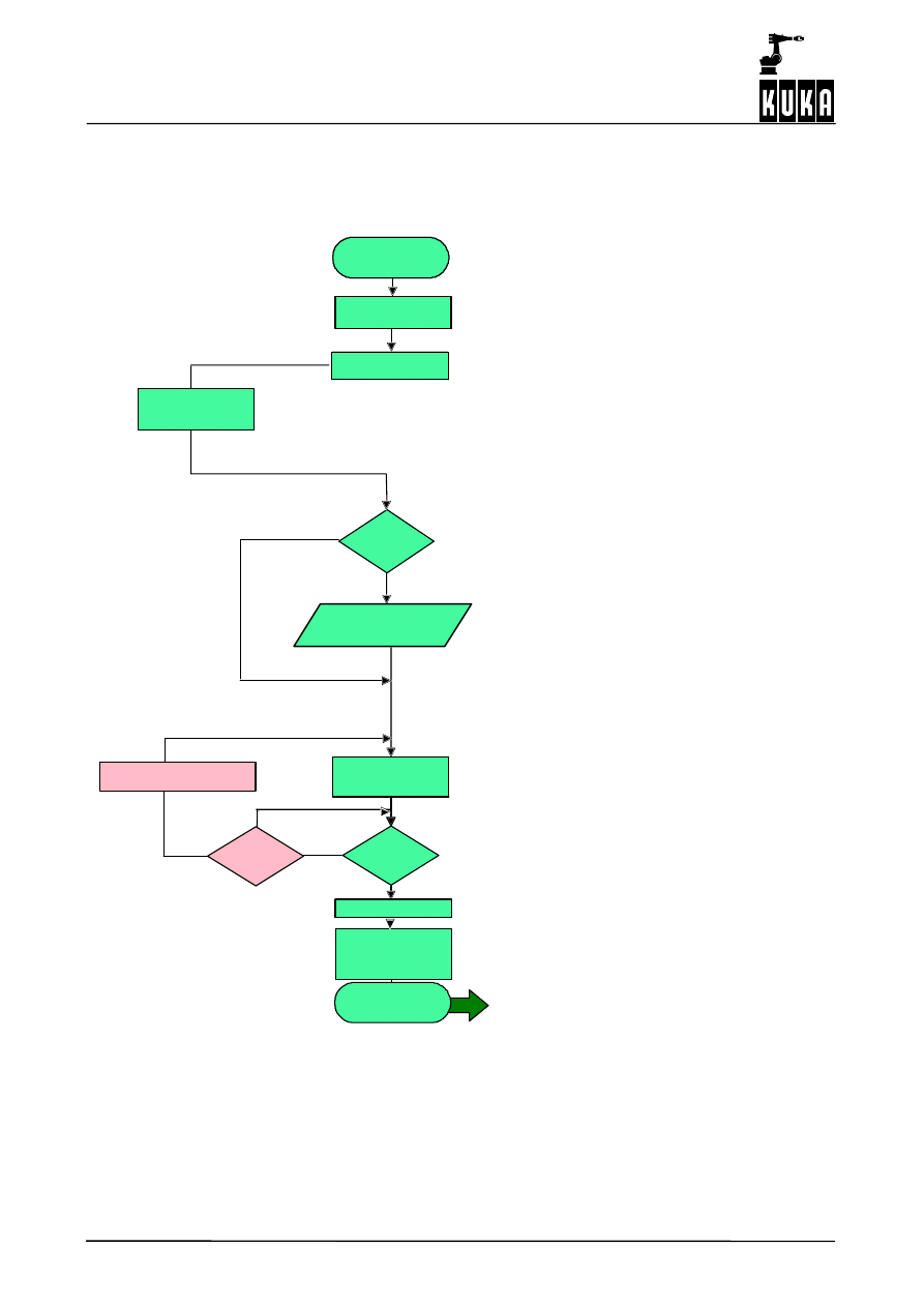
2.2.1
Schematic sequence diagram ARC ON
For the purposes of simplicity, not all options are illustrated.
Initialization
Weld start
Current
flowing
Ignition fault message
Activation of
monitoring
system
End
ARC ON
ARC ON
N
Y
Process continued with the next ARC OFF
or ARC SWITCH command
Prg_ON_MODE
< > 0
I_WELD_COND[ ]
O_WELD_START[ ]
I_START_MOVE[ ]
O_ACK_START[ ]
Standby
test
(Option polled)
I_ENB_W_EXT [ ]
Positioning motion
to ignition position
Synchronization
Timeout
Y
(Poll to see if power source ready)
(Keyswitch polled)
(Weld ON softkey)
Ignition program
number output
2
Description of the “ArcTechDigital” commands (continued)
13 of 68
ArcTechDig_P_R23 04.07.00 en
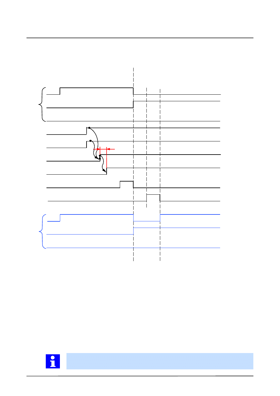
2.2.2
Signal diagram ARC_ON and ARC_SWI
ARC_ON
ARC_SWI
P0
P1
P2
I_WELD_COND [ ]
I_ENB_W_EXT [ ]
O_WELD_START [ ]
I_START_MOVE [ ]
(O_ACK_START [ ] )
O_STROB_PGNO
Ignition
time
if PRG_ON_MODE<> 0
Prog. no. = 1
Prog. no. = 2
P0’
P1’
P2’
PR
G
_SW
I_
MO
D
E
=
2
Prog. no. = 1
Prog. no. = 2
Prog. no. = 3
PR
G
_SW
I_
MO
D
E
=
1
2.3
Welding and ending seams -- ARC OFF
The welding command “ARC OFF” contains the program number for the power source, the
motion parameters and, if relevant, the mechanical weaving parameters used for a single
seam from a weld start (ARC ON) to the end of the seam, and also parameters for crater
filling. A single seam therefore requires at least two commands, namely “ARC ON” and “ARC
SWITCH”.
If a seam consists of several seam sections with different motion and/or weld parameters,
the command “ARC OFF” is used for the last seam section.
Motions from the ignition point (ARC ON), or in case of several seam sections from the target
point of the last section of an “ARC SWITCH” command to the end point of the seam, can
be “LIN” or “CIRC” motions.
Approximate positioning to the next motion block is not possible with “ARC OFF”; the
motion concludes with the exact positioning at the target point (end of the seam).
ArcTechDigital 2.3
14 of 68
ArcTechDig_P_R23 04.07.00 en
2.3.1
Schematic sequence diagram ARC OFF
End
ARC OFF
ARC OFF
Current off
I_WELD_END[ ]
O_SEAM_END[ ]
Positioning motion to
the end point with
weld velocity of the
ARC_OFF command
O_STROB_PGNO[ ]
Program number output
Program number
transfer
Cancel weld start
signal at end
position
Y
N
O_ACK_WELD_E[ ]
Synchronization
2
Description of the “ArcTechDigital” commands (continued)
15 of 68
ArcTechDig_P_R23 04.07.00 en
2.3.2
Signal diagram ARC_OFF
ARC_SWI
ARC_OFF
P0
P1
P2
Prog. no. = 6
PRG_SWI_MODE = 1
Prog. no. = 5
O_STROB_PGN0 [ ]
O_SEAM_END [ ]
I_WELD_END [ ]
Crater time
+
Burnback time
+
Gas postflow time
P0’
P1’
P2’
Prog. no. = 5
O_ACK_WELD_E[ ]
PR
G
_SWI_
M
O
D
E
=
2
PR
G
_SWI_
M
O
D
E
=
1
2.4
Welding a seam in several sections -- ARC SWITCH
The command “ARC” (shown as “ARC SWITCH” in the menu) is used between the
commands “ARC ON” and “ARC OFF” when the seam is divided into several sections with
different motion and/or weld parameters.
ARC SWITCH contains the program number, the motion parameters for the current section
of the seam, and also the parameters for the weld velocity and the mechanical weaving for
the current section of the seam.
In the interest of efficient operations, approximate positioning should be used for motions
in “ARC SWITCH” commands if exact positioning between individual seam sections is not
absolutely essential.
ArcTechDigital 2.3
16 of 68
ArcTechDig_P_R23 04.07.00 en
2.4.1
Schematic sequence diagram ARC SWITCH
Positioning motion to
the end point with
weld velocity of the
ARC_SWI command
End
ARC SWITCH
ARC SWITCH
O_STROB_PGNO[ ]
Program number output
Program number
transfer
Process continued with the next ARC OFF
or ARC SWITCH command
2
Description of the “ArcTechDigital” commands (continued)
17 of 68
ArcTechDig_P_R23 04.07.00 en
2.4.2
Signal diagram ARC_SWI
ARC_ON
ARC_SWI
P0
P1
P2
I_WELD_COND [ ]
I_ENB_W_EXT [ ]
O_WELD_START [ ]
I_START_MOVE [ ]
(O_ACK_START [ ] )
O_STROB_PGNO
Ignition
time
if PRG_ON_MODE<> 0
Prog. no. = 1
Prog. no. = 2
PRG_SWI_MODE = 1
P0’
P1’
P2’
PR
G
_SW
I_
MO
D
E
=
2
Prog. no. = 1
Prog. no. = 2
Prog. no. = 3
PR
G
_SW
I_
MO
D
E
=
1

ArcTechDigital 2.3
18 of 68
ArcTechDig_P_R23 04.07.00 en
3
Programs of the ArcTechDigital package
19 of 68
ArcTechDig_P_R23 04.07.00 en
3
Programs of the ArcTechDigital package
3.1
Program structure
In the following block diagram the program structure of the KR C1 robot controller is shown
in the “Welding robot” configuration.
The interface to the welding controller is implemented in the form of a configurable “hand-
shake”. Settings for analog outputs as well as digital outputs and inputs are defined in the
file “$Config.dat”.
.dat
.dat
Cell.src
$Config.dat.
A20.src
IR_Stopm.src
Flt_serv_d.src
P00.src
Weav_def_d.src
Bas.src
Sps.sub
Switch--off
routine
after an
interpreter stop
A20
GLOBALS
Global and
application
data
Autom./Ext.
organization
program
General
handling
of robot faults
Functions
for
robot
motion
Functions for
Autom./Ext.
Handshake
Check Home
User--
definable
fault
service
functions
Definition and
parameters
for
mechanical
weaving
Functions
for
arc
welding
Information about the hardware periphery of the robot controller can be found in the
[Operating Handbook], chapter “Connector panel / Peripheral interfaces” and in the
[Periphery] handbook.

ArcTechDigital 2.3
20 of 68
ArcTechDig_P_R23 04.07.00 en
3.2
Overview of the “ArcTechDigital” files
The files listed below are included in the “ArcTechDigital” package. To assist you in finding
relevant information, you will always see the symbols shown on the left with their file names
throughout this documentation wherever the corresponding file or parts of it are described.
$Config.dat
Contains data specific to ArcTechDigital within the section
;FOLD ARCTECHDIGITAL GLOBALS
;
FOLD Structures and Definitions
...
;
ENDFOLD (Structures and Definitions)
;
FOLD Main Options
...
;
ENDFOLD (Main Options)
;
FOLD ArcTech Outputs
...
;
ENDFOLD (ArcTech Outputs)
;
FOLD ArcTech Inputs
...
;
ENDFOLD (ArcTech Inputs)
;
FOLD Default Datasets
...
;
ENDFOLD (Default Datasets)
;
FOLD Statuskey Variables
...
;
ENDFOLD (Statuskey Variables)
;
FOLD Peripheral Output groups
;
outputs weld start
...
;
outputs acknowledge start move
...
;
strobe program number
...
;
outputs weld end
...
;
outputs acknowledge weld_end
...
;
outputs fault while arc on
...
;
outputs stop weld after interrupt on seam
...
;
outputs stop cleaner after interrupt
...
;
outputs acknowledge fault
...
;
output for fault message
...
;
Wirefeed control
...
;
ENDFOLD (Peripheral Output groups)
3
Programs of the ArcTechDigital package (continued)
21 of 68
ArcTechDig_P_R23 04.07.00 en
;
FOLD Peripheral Input groups
;
inputs as condition befor weld can start
...
;
inputs start moving
...
;
inputs weld is ended
...
;
Counter for Interrupt definition
...
;
inputs telling faults while welding
...
;
input for external enable weld
...
;
ENDFOLD (Peripheral Input groups)
;
FOLD Internal System States
...
;
ENDFOLD (Internal System States)
;ENDFOLD (ARCTECHDIGITAL GLOBALS)
For additional entries, the section User--defined Variables
in the file “$CONFIG.DAT” is available.
A20.src
Main program for arc welding with “ArcTechDigital”.
A20.dat
Local data list for the program “A20.SRC”.
Flt_serv_d.src
Program for fault strategies defined by the user, including ignition faults.
Fault service function (additional START error).
Flt_serv_d.dat
Contains local data list for the program “FLT_SERV.SRC”.
Weav_def_d.src Definition of the patterns for mechanical weaving.
You will see the following symbols at various points in this documentation; they indicate
whether manual changes are permitted in the section of a file being described.
Within the section / block shown, the changes or entries described must be made.
Within the section / block shown, no changes or entries may be made.

ArcTechDigital 2.3
22 of 68
ArcTechDig_P_R23 04.07.00 en
4
ArcTechDigital -- basic settings
23 of 68
ArcTechDig_P_R23 04.07.00 en
4
ArcTechDigital -- basic settings
4.1
Activating the ARC 20 option
You must make, or check, the basic settings described below for operation with
“ARC Tech 20”.
The “ARC20” option must always be activated (TRUE) when executing ArcTechDigital
applications. At the same time it must be ensured that the variable “A10_OPTION” is inactive
(DISABLED).
Corresponding entries using the menu function “Monitor -- Variable -- Single”
Variable
Value for ArcTechDigital
Characteristics
ARC20
TRUE
(default)
ArcTechDigital applications
ARC20
FALSE
Normal, except ArcTechDigital
4.2
Minimum configuration for power source interface
Signals for basic signal traffic are located in the configuration file.
Digital outputs
Fold ArcTech Outputs in “$Config.dat”
Digital outputs
Configure physical output
$Config.dat
ArcTechDigital 2.3
24 of 68
ArcTechDig_P_R23 04.07.00 en
Digitale Eingänge
Fold ArcTech Inputs in “$Config.dat”
Digital inputs
Configure physical input
4
ArcTechDigital -- basic settings (continued)
25 of 68
ArcTechDig_P_R23 04.07.00 en
4.3
Minimum configuration for program number control
ArcTechDigital permits a variety of coding systems for program numbers for the purpose of
ensuring compatibility with the various welding controllers that are used.
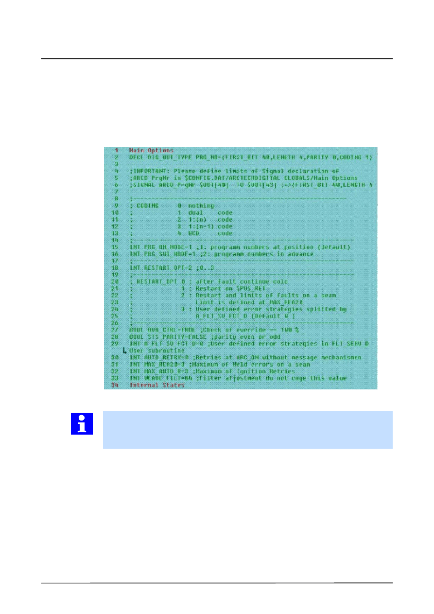
Some Folds from the file ”A20.dat” (in the directory “...\R1\TP\ArcTechDigital”):
Fold Main Options in “A20.dat”
Info
The signal declaration “SIGNAL ARCD_ProgNr $OUT[from] TO $OUT[to]” must corres-
pond to the signal declaration of$Config.dat. If they do not correspond, the program
number output will not function.
A20.dat
ArcTechDigital 2.3
26 of 68
ArcTechDig_P_R23 04.07.00 en
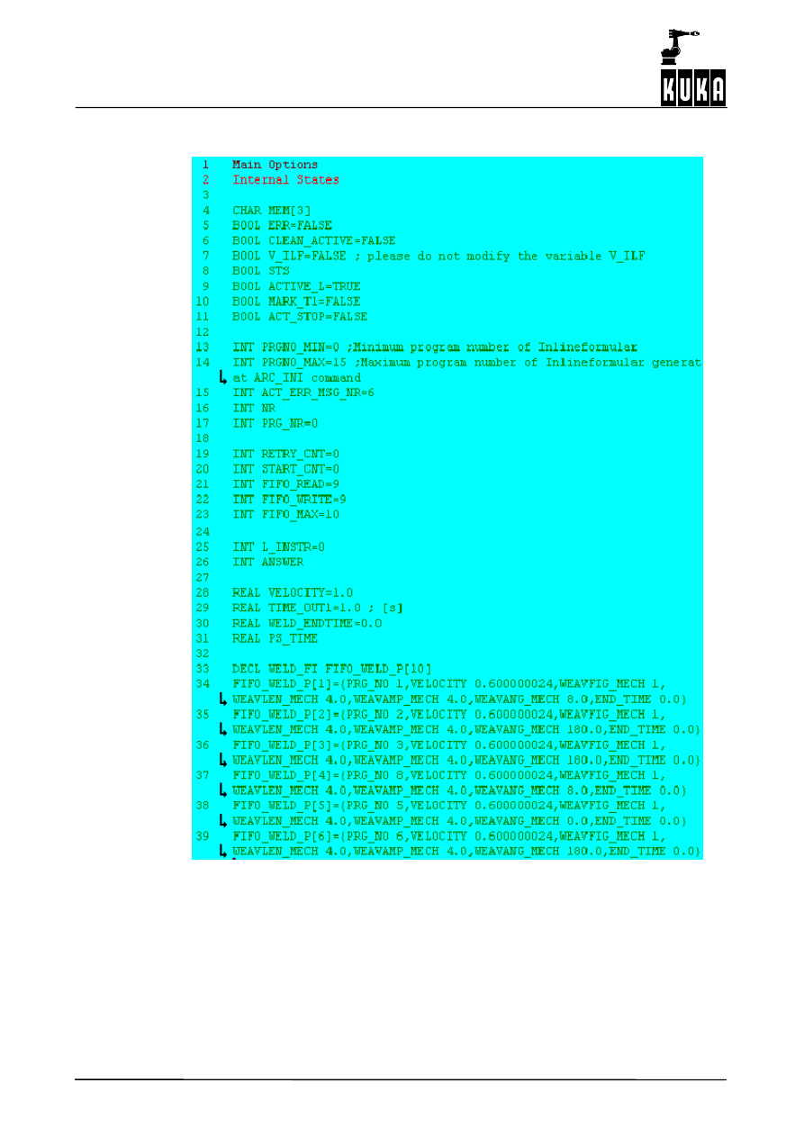
Fold Internal States in “A20.dat”
4
ArcTechDigital -- basic settings (continued)
27 of 68
ArcTechDig_P_R23 04.07.00 en
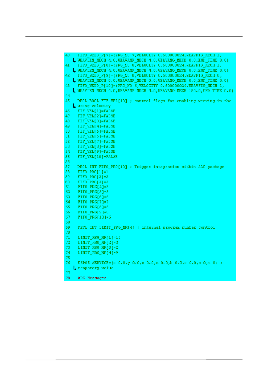
Fold Internal States in “A20.dat” (Fortsetzung)
ArcTechDigital 2.3
28 of 68
ArcTechDig_P_R23 04.07.00 en
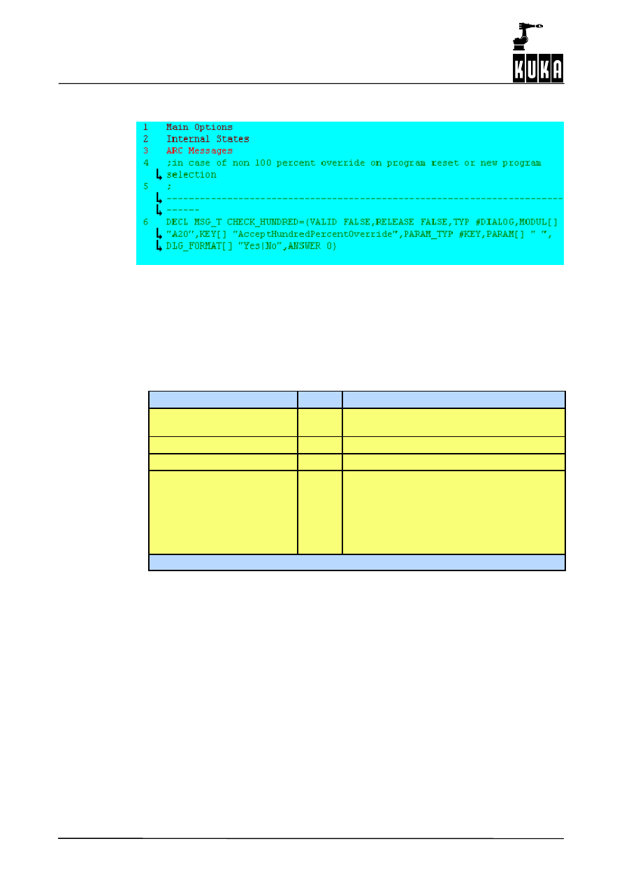
Fold ARC Messages in “A20.dat”
4.3.1
Meaning of the variables
Corresponding entry using the menu function “Monitor” → “Variable” → “Single”:
Variable
Type
Characteristics
PRG_NO.FIRST_BIT
INT
Represents the physical output number of the
first bit. Default = 0
PRG_NO.LENGTH
INT
Specification of the number of bits. Default = 4
PRG_NO.PARITY
INT
Output number for the parity bit.
PRG_NO.CODING
INT
Coding of the program numbers.
-- Coding 1
= dual
-- Coding 2
= 1 of n
-- Coding 3
= 1 of (n--1)<
-- Coding 4
= BCD code
Default = 1

5
Principles of the definable signal table
29 of 68
ArcTechDig_P_R23 04.07.00 en
5
Principles of the definable signal table
This section describes the definition of the “ArcTechDigital” peripheral interfaces, their spe-
cific adaptation as well as configurable options:
5.1
Overview, definition
5.1.1
Index tables for configuring physical outputs and inputs
For the purpose of configuring the physical outputs and inputs, two index tables are provided
in the block “FOLD A20” in the file “$Config.dat”.
G
Digital outputs
Digital control signals from the robot controller to the
(DIGITAL OUTPUTS)
welding controller -- e.g. “Weld start”, “Gas manual”;
G
Digital inputs
Digital control signals from the welding controller to the
(DIGITAL INPUTS)
robot controller -- e.g. “Arc struck”, “Weld end”.
In these index tables the assignment of the physical outputs and inputs is defined and refer-
ences are made to the corresponding signal tables of the controller. This has the advantage
that if the terminal assignments for the periphery are changed, it is merely necessary to alter
the index tables accordingly.
5.1.2
Signal tables for digital outputs and inputs
The interface concepts are variable. Configuring peripheral outputs and inputs by means of
signal tables (so--called “triple groups”) allows processes to run synchronously. The capabil-
ity of setting or scanning several signals makes it possible for various welding controllers to
be adapted and the timing to be optimized.
Signal names of a group beginning with “O_...” designate digital outputs, and those with “I_...”
designate digital inputs.
These options are stored in variables that are defined in the file $CONFIG.DAT, FOLD A20
GLOBALS. Settings are stored in this file. You can use the edit function to set or change the
values of the variables in “$CONFIG.DAT”.
In addition, menu--prompted viewing and alteration of the variable values is also possible.
.
For this purpose, a list can be opened in the status window by means of the menu “Monitor
-- Variable -- Single”.
.
The current value is shown when the variable name is entered. You
change this value by entering a new value in the field “New value”.
A syntax check is not performed (for example, MIN and MAX values) when entries are
made with the menu function “Monitor -- Variable -- Single” or when the file is edited.
Further information on the ARC 20 signal tables contained in “$CONFIG.DAT” is provided
in the descriptions of the various welding commands (ARC ON, ARC OFF, ARC SWITCH)
in Section 3.
$Config.dat
$Config.dat
ArcTechDigital 2.3
30 of 68
ArcTechDig_P_R23 04.07.00 en
5.2
Digital outputs
5.2.1
Index table for physical digital outputs
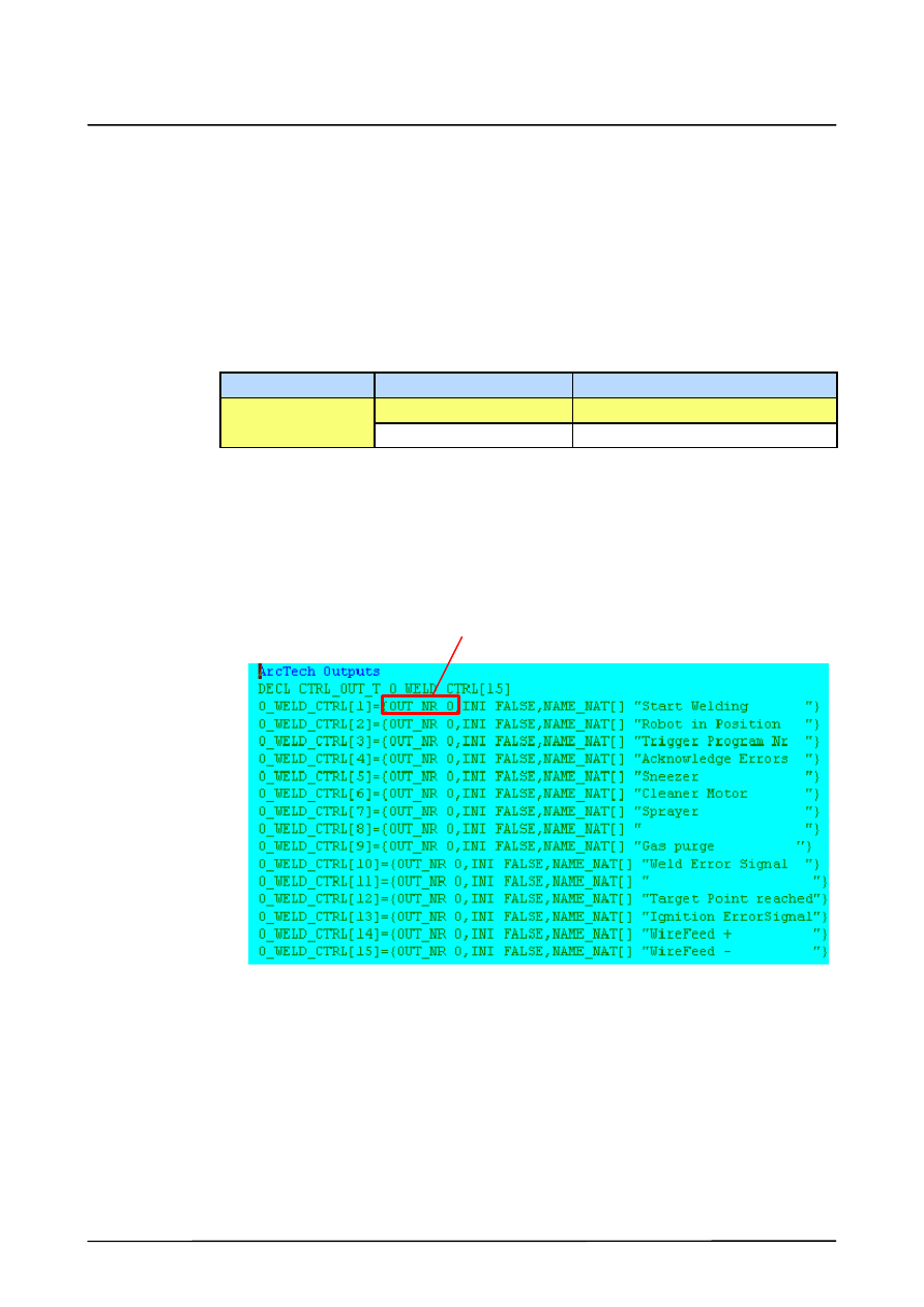
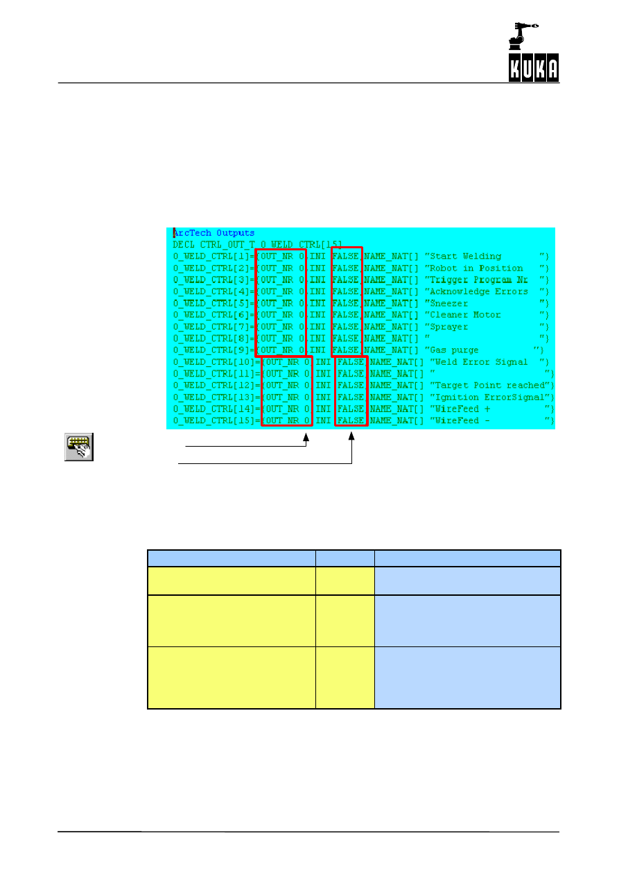
Altogether 15 digital outputs (O_WELD_CTRL[1] ... [O_WELD_CTRL[15]) are available;
their physical assignment (OUT_NR n) is freely definable.
Fold ArcTech Outputs in “$Config.dat”
Comment (signal name)
Physical outputs
State at initialization
Example of corresponding entries using the menu function “Monitor -- Variable -- Single”:
Variable
Type
Characteristics
O_WELD_CTRL[1].OUT_NR
INT
Assignment of the physical output,
e.g. “10” (default: 0)
O_WELD_CTRL[1].INI
BOOL
State at initialization
(default: FALSE)
FALSE = LOW
TRUE = HIGH
O_WELD_CTRL[1].NAME_NAT[ ]
STRING
20 characters between “ ”; please
note that if the string is changed, any
characters not overwritten (possibly
because they are not visible in the
window) will be retained.
All “O_WELD_CTRL[1].OUT_NR” array elements are set to “0” at the factory, meaning they
are inactive. The element “INI” defines the state to which the respective physical output
“OUT_NR” is to be set on initialization. The value “FALSE” sets the output to “LOW”, the
value “TRUE” to “HIGH”.
The “NAME_NAT[ ]” entries (signal name) are comments with a string length of 20 characters
between the quotation marks (“...”) whose content may be altered (while retaining the string
length!).
5
Principles of the definable signal table (continued)
31 of 68
ArcTechDig_P_R23 04.07.00 en
If you make any changes to the comments (signal name) “NAME_NAT” directly in the
file “$CONFIG.DAT” please ensure that the length of the string between the quotation
marks (“ ”) is exactly 20 characters long; use blanks if required.
If you use the menu function “Monitor -- Variable -- Single” to make changes, an error
message is displayed if the string exceeds 20 characters.
The following example shows the assignment of the physical outputs and the signal states
after initialization.
O_WELD_CTRL[1]={OUT_NR 10,INI FALSE,NAME_NAT[] “...”}
Output 10
DIGITAL OUTPUTS
Index table
INI
LOW
HIGH
WELD START
Array “O_WELD_CTRL[n] INI” contains the initial value when the INIT routine is running
before reaching the block coincidence movement.
5.2.2
Signal tables for digital outputs
5.2.2.1 Definition of the signal states
Up to three outputs can be controlled and for each of these outputs the following parameters
can be defined.
Output parameters
Characteristics
{NO 0,PULS_TIME 0.0,STATE TRUE}
Index disabled (ignored)
{NO 1,PULS_TIME 0.0,STATE TRUE}
Index NO 1 (refers to field 1 of the index
table “O_WELD_CTRL[1]”) with static
HIGH signal
{NO 2,PULS_TIME 0.0,STATE FALSE}
Index NO 2 (refers to field 2 of the index
table “O_WELD_CTRL[2]”) with static
LOW signal
{NO 3,PULS_TIME 1.0,STATE TRUE}
Index NO 3 (refers to field 3 of the index
table “O_WELD_CTRL[3]”) with HIGH
pulse (length: 1 s)
If “NO” is set to “0” (zero), the index is deactivated and is ignored during execution of
the program.
ArcTechDigital 2.3
32 of 68
ArcTechDig_P_R23 04.07.00 en
5.3
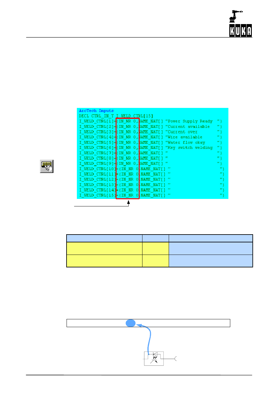
Digital inputs
5.3.1
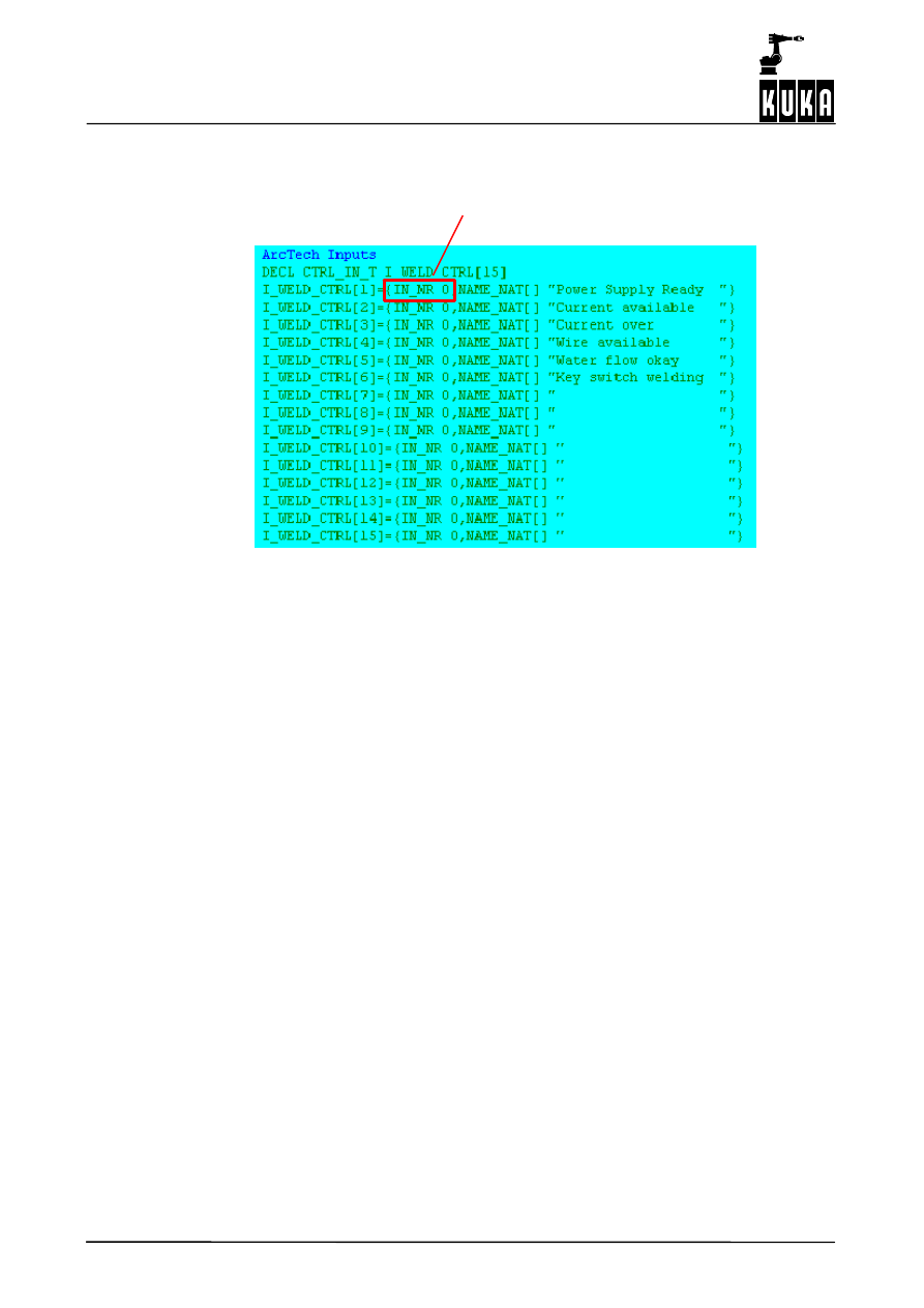
Index table for physical digital inputs
Altogether 15 digital inputs (I_WELD_CTRL[1] ... I_WELD_CTRL[15]) are available; their
physical assignment (IN_NRn) is freely definable. All “IN_NR” array elements are set to “0”
at the factory, meaning they are inactive. For the purpose of assigning the physical inputs,
you can enter their corresponding numbers in the index table “DIGITAL INPUTS” of the file
“$CONFIG.DAT”:
Fold ArcTech Inputs in “$Config.dat”
Comment (signal name)
Physical inputs
Example of corresponding entries using the menu function “Monitor -- Variable -- Single”:
Variable
Type
Characteristics
I_WELD_CTRL[1].IN_NR
INT
Assignment of the physical input,
e.g. “2” (default: 0)
I_WELD_CTRL[1].NAME_NAT[ ]
STRING
20 characters between “ ”; any char-
acters not overwritten will be retained.
All “IN_NR” array elements are set to “0” at the factory, meaning they are inactive. The
“NAME_NAT[ ]” entries (signal name) are comments with a string length of 20 characters
between the quotation marks (”...”) whose content may be altered while retaining the
string length. Also see the note in Section 5.2.1.
The following example illustrates the assignment of the physical inputs. “I_WELD_CTRL[1]”
is assigned to physical input no. 2.
I_WELD_CTRL[1]={IN_NR 2,NAME_NAT[] “WELD SOURCE READY”}
DIGITAL INPUTS
Input 2
Signals to:
IN_NR 0 = input disabled
Index table “DIGITAL INPUTS” ($CONFIG.DAT, FOLD A20 GLOBALS)
5
Principles of the definable signal table (continued)
33 of 68
ArcTechDig_P_R23 04.07.00 en
5.3.2
Signal tables for digital inputs
Up to three inputs can be scanned. The following states can be checked for each of these
inputs:
Input parameter
Characteristics
{NO 0,STATE TRUE}
NO 0: input disabled (ignored)
{NO 1,STATE TRUE}
A HIGH signal is awaited at the physical input
referring to field 1 of the index table
“I_WELD_CTRL[ ]”.
{NO 2,STATE FALSE}
A LOW signal is awaited at the physical input
referring to field 2 of the index table
“I_WELD_CTRL[ ]”.
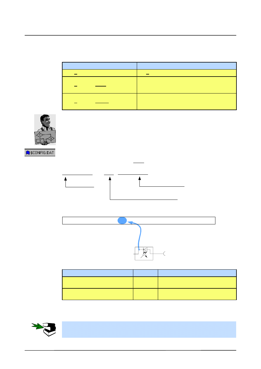
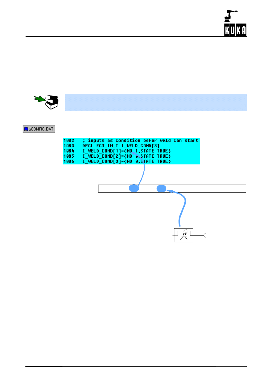
The following example shows a signal table from the file “$CONFIG.DAT” for a digital input.
The element “I_WELD_COND[1].NO” with the value “2” refers to array 2 of the index table
“DIGITAL INPUTS” (I_WELD_CTRL[15]) and thus to the physical input configured in it (see
Section 5.3).
The element “STATE” specifies the awaited state, in this case “TRUE”.
; inputs as condition before weld can start
DECL FCT_IN_T I_WELD_COND[3]
I_WELD_COND[1]={NO 1,STATE TRUE}
I_WELD_COND[2]={NO 0,STATE FALSE}
I_WELD_COND[3]={NO 0,STATE FALSE}
Signal name
Status (TRUE = HIGH)
Index for addressing
in index table “I_WELD_CTRL[1 ]”
I_WELD_CTRL[1]={IN_NR 2,NAME_NAT[] “WELD SOURCE READY”}
DIGITAL INPUTS
Input 2
Signals to:
IN_NR 0 = Input disabled
Index table “DIGITAL INPUTS” ($CONFIG.DAT, FOLD A20 GLOBALS)
Example of corresponding entries using the menu function “Monitor -- Variable -- Single”:
Variable
Type
Characteristics
I_WELD_COND[1].NO
INT
Assignment of the physical input,
e.g. “2” (default: 0)
I_WELD_COND[1].STATE
BOOL
Awaited state
Default: FALSE
Two other input signals are defined in this example as the second and third conditions that
have to be met before welding can be started.
Information on the definition of the terms “index table” and “signal table” can be found in
Section 6.1.

ArcTechDigital 2.3
34 of 68
ArcTechDig_P_R23 04.07.00 en
6
Assignment of the signal grouping in normal operation
35 of 68
ArcTechDig_P_R23 04.07.00 en
6
Assignment of the signal grouping in normal operation
The signal tables provide the capability of defining up to three signals, i.e. of activating up
to three different physical outputs with different signal levels by means of one event.
There is of course no practical application for this setting; this example is merely intended
to illustrate that the reason for missing or incorrect peripheral signals can be an incorrect
value assignment. In such cases, it is therefore advisable to check the setting of the
variables before looking for faults in the hardware.
6.1
Assignment of the outputs
The blocks with a gray background show the pre--configuration and do not normally need to
be changed.
See also Section 4.2 Minimum configuration for power source interface.
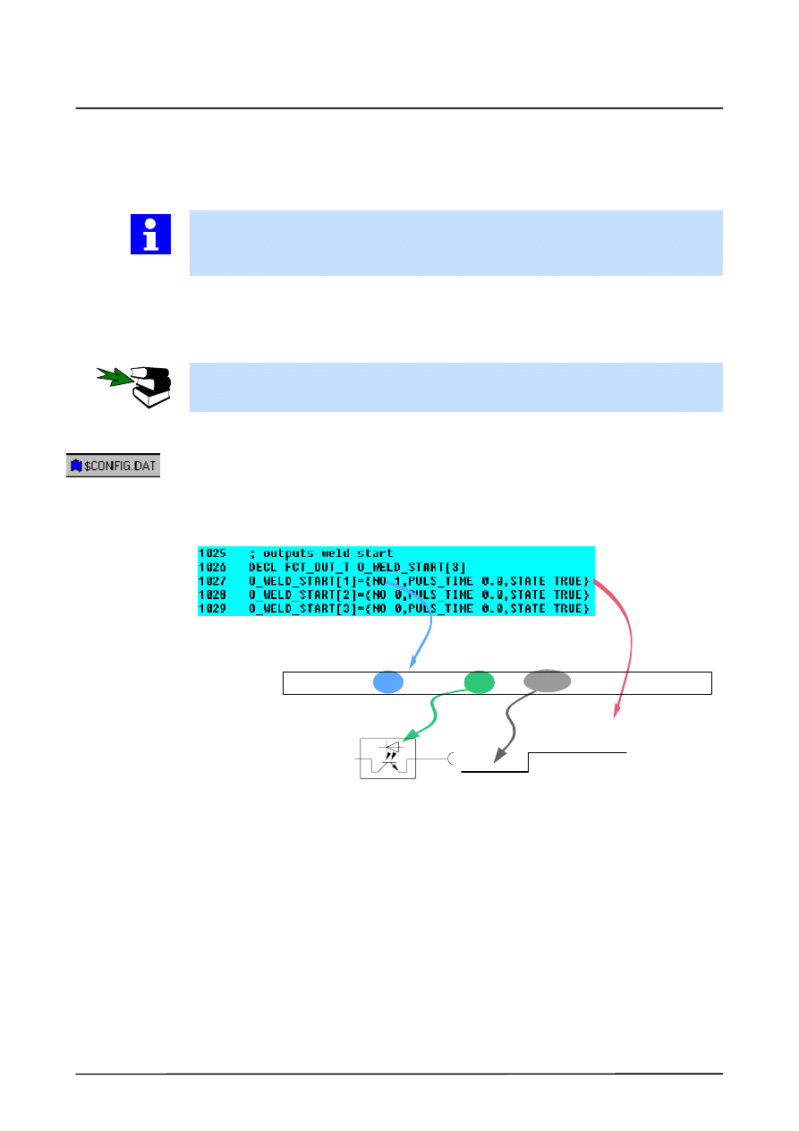
6.1.1
Output group O_WELD_START [ ]
The “Weld Start” signal should be assigned to physical output 10. The signal level should be
LOW at initialization and statically HIGH at the start of welding.
In the index table “Digital Outputs”, the designation (NAME_NAT) “Weld Start” and “INI” =
FALSE are already entered in the first line “O_WELD_CONTROL[1]”. Assign the value “10”
to the variable “OUT_NR”.
O_WELD_CTRL[1]={OUT_NR 10,INI FALSE,NAME_NAT[] “...”}
Output 10
DIGITAL OUTPUTS
Index table
INI
LOW
HIGH
WELD START
In the signal table “outputs weld start”, assign the value “1” to the variable “NO” in the first
line “O_WELD_START[1]”. The signal level should be static, so enter the value “0.0” for
“PULS_TIME”.
The element “PULSE_TIME” allows the programming of pulse times, if they are not overwrit-
ten by the current programming by means of inline forms or parameter lists. An output can
be static (PULSE_TIME 0.0) or be output in the form of a pulse, in which case the pulse dura-
tion is programmed in seconds. For example, “PULSE_TIME 0.3” corresponds to a pulse
duration of 0.3 seconds.
ArcTechDigital 2.3
36 of 68
ArcTechDig_P_R23 04.07.00 en
Entries made using the menu function “Monitor -- Variable -- Single”:
Variable
Type
Characteristics
O_WELD_START[1].NO
INT
Assignment to element in index table,
e.g. “1” (default: 0)
O_WELD_START[1].PULS_TIME
REAL Pulse duration in seconds
Default: 0.0 (static)
O_WELD_START[1].STATE
BOOL Active state
Default: FALSE
6.1.2
Output group O_ACK_START [ ]
The “O_ACK_START[ ]” signal informs the welding controller that the robot has started to
move. Assign the value “11” to the variable “OUT_NR” and set “INI” = TRUE.
Output 11
DIGITAL OUTPUTS
Index table
INI
LOW
HIGH
ACK START
O_WELD_CTRL[2]={OUT_NR 11,INI FALSE,NAME_NAT[] “...”}
Please note that “PULS_TIME” and “STATE” must be configured accordingly because
the signal is not otherwise reset.
Example:
O_ACK_WELD_E[1]={NO 12, PULS_TIME 0.5,STATE TRUE}
6
Assignment of the signal grouping in normal operation (continued)
37 of 68
ArcTechDig_P_R23 04.07.00 en
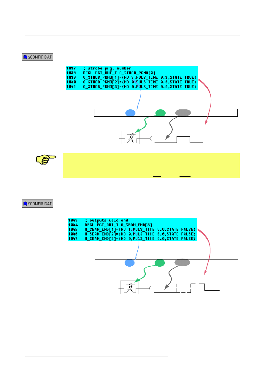
6.1.3
Output group O_STROB_PGNO [ ]
The “TRIGGER PROGRAM NO.” signal to the welding controller defines the validity of the
program number. Assign the value “12” to the variable “OUT_NR”.
STROB_PGNO
Output 12
DIGITAL OUTPUTS
Index table
INI
LOW
HIGH
O_WELD_CTRL[3]={OUT_NR 12,INI FALSE,NAME_NAT[] “...”}
Please note that “PULS_TIME” and “STATE” must be configured accordingly because
the signal is not otherwise reset.
Example:
O_STROB_PGNO[1]={NO 3, PULS_TIME 0.3,STATE TRUE}
6.1.4
Output group O_SEAM_END [ ]
End of seam reached, crater filling can begin -- O_SEAM_END[ ]. Assign the value “10” to
the variable “OUT_NR”.
The configured signal cancels the WELD_START signal following the ARC_OFF command.
Output 10
DIGITAL OUTPUTS
Index table
INI
LOW
HIGH
O_WELD_CTRL[1]={OUT_NR 10,INI FALSE,NAME_NAT[] “...”}
ARC_ON
ArcTechDigital 2.3
38 of 68
ArcTechDig_P_R23 04.07.00 en
6.1.5
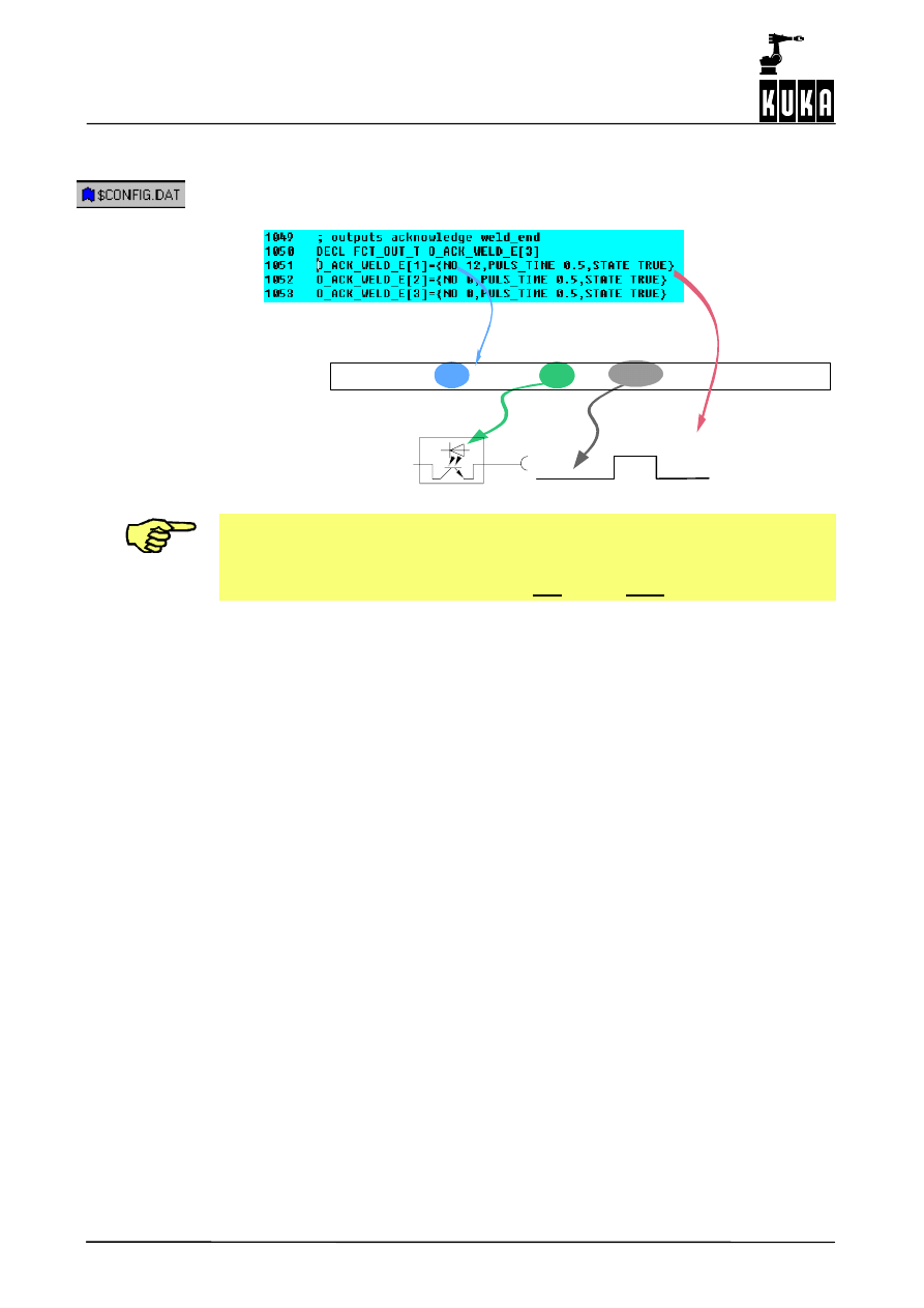
Output group O_ACK_WELD_E[ ]
Activated when the weld is finished and the crater has been filled, this output signal enables
the program to be continued. Assign the value “14” to the variable “OUT_NR”.
Output 14
DIGITAL OUTPUTS
Index table
INI
LOW
HIGH
O_WELD_CTRL[12]={OUT_NR 14,INI FALSE,NAME_NAT[] “...”}
ACK_WELD_E
Please note that “PULS_TIME” and “STATE” must be configured accordingly because
the signal is not otherwise reset.
Example:
O_ACK_WELD_E[1]={NO 12,PULS_TIME 0.5,STATE TRUE}
6
Assignment of the signal grouping in normal operation (continued)
39 of 68
ArcTechDig_P_R23 04.07.00 en
6.2
Signal output groups for fault service function
6.2.1
Output group O_FLT_ARC_ON [ ]
This output signal group means that a fault occurred during the ARC_ON command. An igni-
tion fault output is set and, at the same time, the “WELD_START” signal is cancelled. Assign
the value “15” or “10” to the variable “OUT_NR”.
Output 10
Index table
INI
LOW
HIGH
O_WELD_CTRL[1]={OUT_NR 10,INI FALSE,NAME_NAT[] “...”}
FLT_ARC_ON
Output 15
DIGITAL OUTPUTS
INI
LOW
HIGH
O_WELD_CTRL[13]={OUT_NR 15,INI FALSE,NAME_NAT[] “...”}
ARC_ON
DIGITAL OUTPUTS
Index table
ArcTechDigital 2.3
40 of 68
ArcTechDig_P_R23 04.07.00 en
6.2.2
Output group O_FLT_WELD [ ]
This output signal switches the welding off and sets an error message for the PLC. Assign
the value “10” or “13” to the variable “OUT_NR”.
Output 10
DIGITAL OUTPUTS
Index table
INI
LOW
HIGH
O_WELD_CTRL[1]={OUT_NR 10,INI FALSE,NAME_NAT[] “...”}
FLT_WELD
Output 13
Index table
INI
O_WELD_CTRL[10]={OUT_NR 13,INI FALSE,NAME_NAT[] “...”}
DIGITAL OUTPUTS
HIGH
LOW
6
Assignment of the signal grouping in normal operation (continued)
41 of 68
ArcTechDig_P_R23 04.07.00 en
6.2.3
Output group O_FLT_CLEAN [ ]
These output signals are used to reset the outputs for torch cleaning. Assign the value “9”
to the variable “OUT_NR”.
Output 9
DIGITAL OUTPUTS
Index table
INI
LOW
HIGH
O_WELD_CTRL[6]={OUT_NR 9,INI FALSE,NAME_NAT[] “...”}
FLT_CLEAN
6.2.4
Output group O_ACK_FLT [ ]
These output signals are used to acknowledge error states. Assign the value “8” to the vari-
able “OUT_NR”.
Output 8
DIGITAL OUTPUTS
Index table
INI
LOW
HIGH
O_WELD_CTRL[4]={OUT_NR 8,INI FALSE,NAME_NAT[] “...”}
ACK_FLT
Please note that “PULS_TIME” and “STATE” must be configured accordingly because
the signal is not otherwise reset.
Example:
O_ACK_FLT[1]={NO 4,PULS_TIME 1.0,STATE TRUE}
ArcTechDigital 2.3
42 of 68
ArcTechDig_P_R23 04.07.00 en
6.3
Assignment of the inputs
The signal tables provide the capability of assigning up to three input signals to a condition.
References to the index table “Digital Inputs” can of course also be made from other signal
tables. If several conditions must be met, accordingly more signals must be configured. The
inputs are polled using logical ANDing.
The signal input groups with a gray background represent the pre--configuration from V2.3
onwards and do not normally need to be adapted.
See also Section 4.2 Minimum configuration for power source interface.
6.3.1
Input group I_WELD_COND [ ]
A precondition for welding is a successful check that the peripheral interface signal “WELD-
ING SOURCE READY” is set. The signal table for “I_WELD_COND[ ]” reads as follows:
Signals awaited
at:
Input 1
HIGH signal
DIGITAL INPUTS
Index table
I_WELD_CTRL[1]={IN_NR 1,NAME_NAT[] “...”}
6
Assignment of the signal grouping in normal operation (continued)
43 of 68
ArcTechDig_P_R23 04.07.00 en
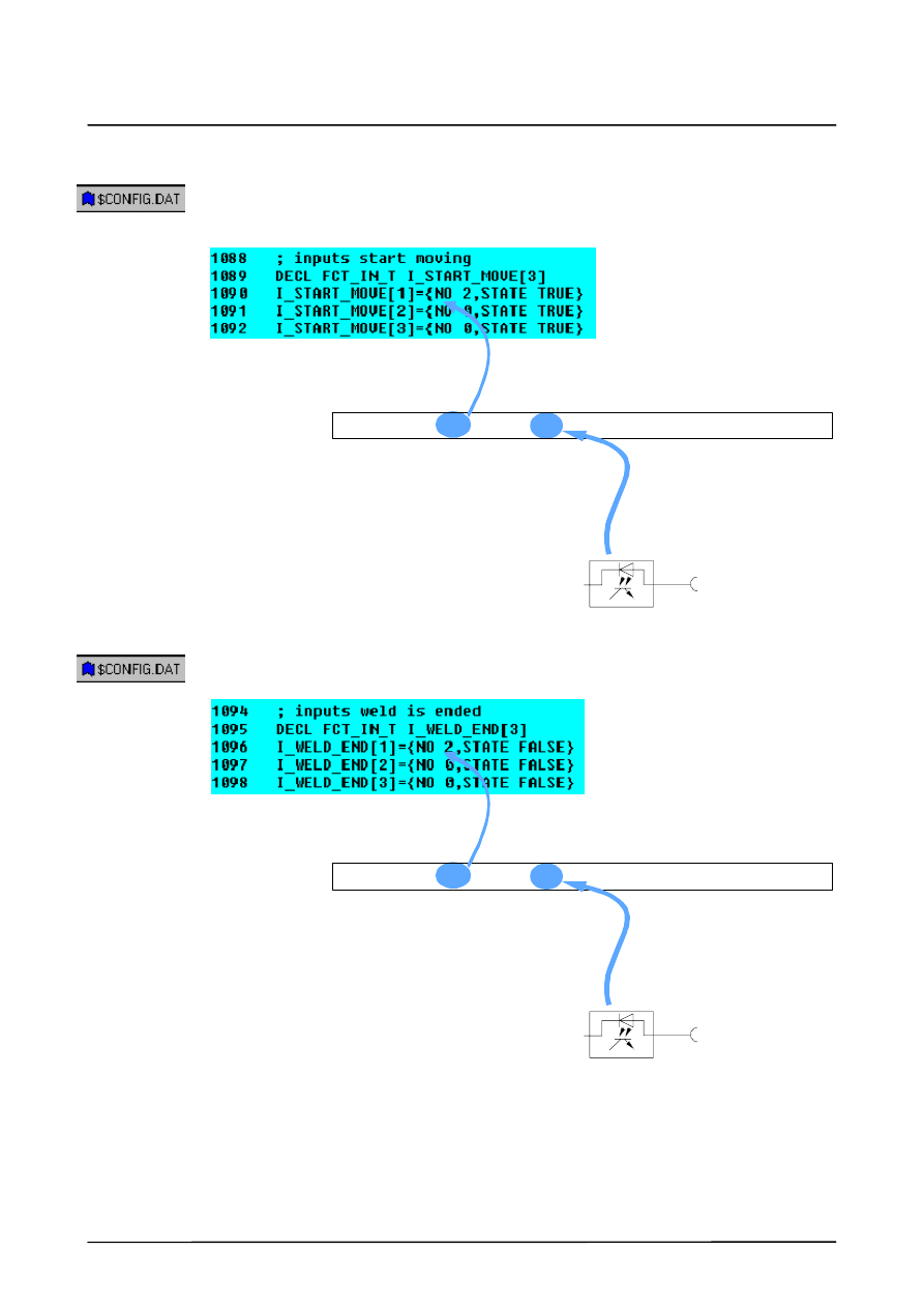
6.3.2
Input group I_START_MOVE [ ]
After successful ignition the welding source supplies the “ARC STRUCK” signal. This signal
is a precondition for the robot to start moving along the path, i.e. for continuation of the
process. The corresponding signal table for “I_START_MOVE[ ]” is as follows:
DIGITAL INPUTS
Index table
I_WELD_CTRL[2]={IN_NR 3,NAME_NAT[] “...”}
Signals awaited
at:
Input 3
HIGH signal
6.3.3
Input group I_WELD_END [ ]
The “WELD END” signal is issued on completion of welding and end crater filling. The
corresponding signal table for “I_WELD_END[ ]” is as follows:
DIGITAL INPUTS
Index table
I_WELD_CTRL[2]={IN_NR 2,NAME_NAT[] “...”}
Signals awaited
at:
Input 2
LOW signal
ArcTechDigital 2.3
44 of 68
ArcTechDig_P_R23 04.07.00 en
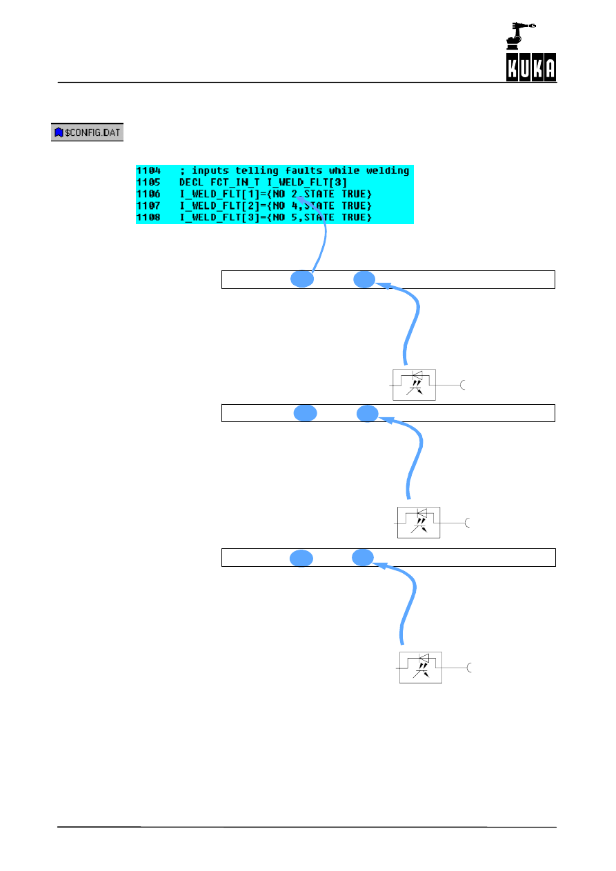
6.3.4
Input group I_WELD_FLT [ ]
The current welding process (ARC OFF, ARC SWITCH) is monitored, the welding controller
supplying a signal in the event of a welding fault or malfunction occurring. The corresponding
signal table for “I_WELD_FLT[ ]” is as follows:
DIGITAL INPUTS
Index table
I_WELD_CTRL[2]={IN_NR 3,NAME_NAT[] “...”}
I_WELD_FLT[2] and [3] generally monitor the
following: shielding gas, cooling or wire feed.
I_WELD_FLT[1] generally monitors the current
flow.
DIGITAL INPUTS
Index table
I_WELD_CTRL[4]={IN_NR 4,NAME_NAT[] “...”}
DIGITAL INPUTS
Index table
I_WELD_CTRL[5]={IN_NR 5,NAME_NAT[] “...”}
Signals awaited
at:
Input 3
HIGH signal
Signals awaited
at:
Input 4
HIGH signal
Signals awaited
at:
Input 5
HIGH signal
6
Assignment of the signal grouping in normal operation (continued)
45 of 68
ArcTechDig_P_R23 04.07.00 en
6.3.5
Polling of the external keyswitch (Hot/Cold)
This keyswitch is used for executing programs without “hot” welding and can only be config-
ured if the welding system is equipped accordingly.
For this purpose, configuration of the physical input in the index table “DIGITAL INPUTS”
(see Section 5.3) is required, as too is the reference to this input in the section “input for exter-
nal enable weld” of the $CONFIG.DAT file.
; input for external enable weld
DECL FCT_IN_T I_ENB_W_EXT={NO 6,STATE TRUE}
Corresponding entry using the menu function “Monitor -- Variable -- Single”:
Variable
Type
Characteristics
I_ENB_W_EXT.NO
INT
Reference to the physical input in the index
table “DIGITAL INPUTS” I_WELD_CTRL[ ].
Default: “6”
I_ENB_W_EXT.STATE
BOOL Default: TRUE
I_WELD_CTRL[6] = {IN_NR 7........}
This entry must be made
6.3.6
Time_out when polling the inputs
The wait time for digital input signals is limited by the variable
; time out while waiting (until fault message)
REAL TIME_OUT1=3.0 ; [s]
After this configurable wait time, the program is stopped and a corresponding error message
is displayed in the message window.
Entries made using the menu function “Monitor -- Variable -- Single”:
Variable
Type
Characteristics
TIME_OUT1
REAL Wait time in seconds, default = 3s
If you receive the message “Object not found” (no. 2047) while viewing or modifying
variables in the file “A20.DAT”, you must set the value of the variable $DATAPATH[] to
“/R1/A20” (the “ ” characters are part of the string).
A20.DAT

ArcTechDigital 2.3
46 of 68
ArcTechDig_P_R23 04.07.00 en
7
Options for program number specification
47 of 68
ArcTechDig_P_R23 04.07.00 en
7
Options for program number specification
7.1
Signal flow of the program numbers
Variable
Type Characteristics
PRG_ON_MODE
INT
Function for ARC ON.
-- PRG_ON_MODE=1: The program number is
set when the point is
reached.
-- PRG_ON_MODE=2: The program number is
set before the point is
reached,
during the
advance run.
Default: 1
PRG_SWI_MODE
INT
Function for ARC SWITCH.
-- PRG_SWI_MODE=1: The program number is
set when the point is
reached.
-- PRG_SWI_MODE=2: The program number is
set before the point is
reached,
during the
advance run.
Default: 1
PRGNO_MIN
INT
Defines the smallest program number.
Default: 0
PRGNO_MAX
INT
Defines the largest program number. *)
Default: 15 corresponding to
PRG_NO.LENGTH = 4
PRGNO
INT
Current program number
PRG_ON_MODE and PRG_SWI_MODE are normally identical.
If PRG_ON_MODE=0, no O_ACK_START[ ] group is set.
7.2
Setting -- parity bit
Parity 0 = default
n = output number
⇒ positive ⇒ “even”
⇒ negative ⇒ “odd”
A20.DAT
ArcTechDigital 2.3
48 of 68
ArcTechDig_P_R23 04.07.00 en
7.3
Timing diagram – program number interface (a)
ARC_O
N
ARC_S
W
I
ARC_S
W
I
ARC_O
F
F
O
_AC
K_
WEL
D
._
E
[]
O
_AC
K_
ST
AR
T
[]
O
_STR
O
B
_PG
N
O
[]
P
rog.
no.
=
4
P
rog.
no.
=
3
P0
P1
P2
P0
P1
P2
PR
G
_SWI_
M
O
D
E
=1
D
ef
ault
P
rog.
=
2
P
rog.
=
3
P
rog.
=
4
P
ro
g.
=
2
fo
r
S
GL
PR
G
_SWI_
M
O
D
E
=
2
ARC_S
W
I
P
ro
g.
=
3
fo
r
S
GL
but
pr
og.
no.
3
is
alr
eady
se
t!
but
pr
og.
no.
4
is
alr
eady
se
t!
P
rogr
am
num
be
r
h
ands
ha
ke
P
rog.
no.
=
2
8
Setting the restart options
49 of 68
ArcTechDig_P_R23 04.07.00 en
8
Setting the restart options
8.1
RESTART_OPTION
Possible reactions to welding faults on the seam are defined by means of the variable
“RESTART_OPT”.
; Variables:
INT RESTART_OPT=1
Default: 1 (range 0 -- 3)
Corresponding entries using the menu function “Monitor -- Variable -- Single” and charac-
teristics:
Variable
Value
Characteristics -- Remedial action
0
In the event of control or welding faults, the seam is
completed without welding after a restart.
1
After welding has been interrupted, the robot repositions
the torch to the point of interruption. Welding is subse-
quently restarted.
If welding is interrupted by pressing the STOP key (inter-
preter stop), the program cannot be restarted.
Remedy: release the Start key after releasing the enab-
ling switch.
RESTART_OPT
2
The same function as with “RESTART_OPT=1”, with the
restriction that the number of permissible welding inter-
ruptions is limited to a maximum value.
This maximum value is defined in the variable
“MAX_REA20”. If this value is exceeded, the seam is
completed without welding and a corresponding
message is generated.
The value specified in “MAX_REA20” (default = 3) is valid
for the entire seam between the commands ARC ON and
ARC OFF.
3
One or more user--defined fault service functions can be
specified. Occurrence of a fault triggers a branch to the
program “FLT_SERV.SRC”. Users can define their own
fault service functions in this program.
8.1.1
Reaction to interpreter stop (STOP key)
Pressing the STOP key triggers an interpreter stop. The welding process and torch cleaning
station are switched off by the constantly--running parallel program “SPS.SUB”. Welding is
not restarted when the Start key on the KCP is pressed.
A20.DAT
ArcTechDigital 2.3
50 of 68
ArcTechDig_P_R23 04.07.00 en
8.2
Configuration in event of ignition faults
8.2.1
Ignition repetition monitoring
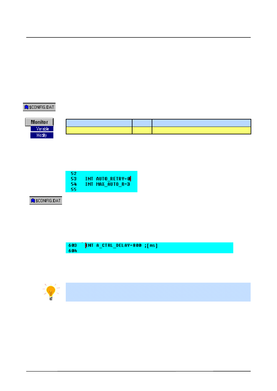
The following variables are available for repeat ignition attempts on a seam:
The number of permissible restart attempts is programmed with the variable
“MAX_AUTO_R”, and the maximum number of welding faults per seam before an error
message is generated is programmed with “MAX_REA20”.
; Variables:
INT MAX_AUTO_R=3
Maximum number of ignition attempts
Corresponding entries using the menu function “Monitor -- Variable -- Single”:
Variable
Value
Meaning for repeat ignition attempts
MAX_AUTO_R
3 (default)
Maximum number of restart attempts
8.3
Ignition fault message suppression option
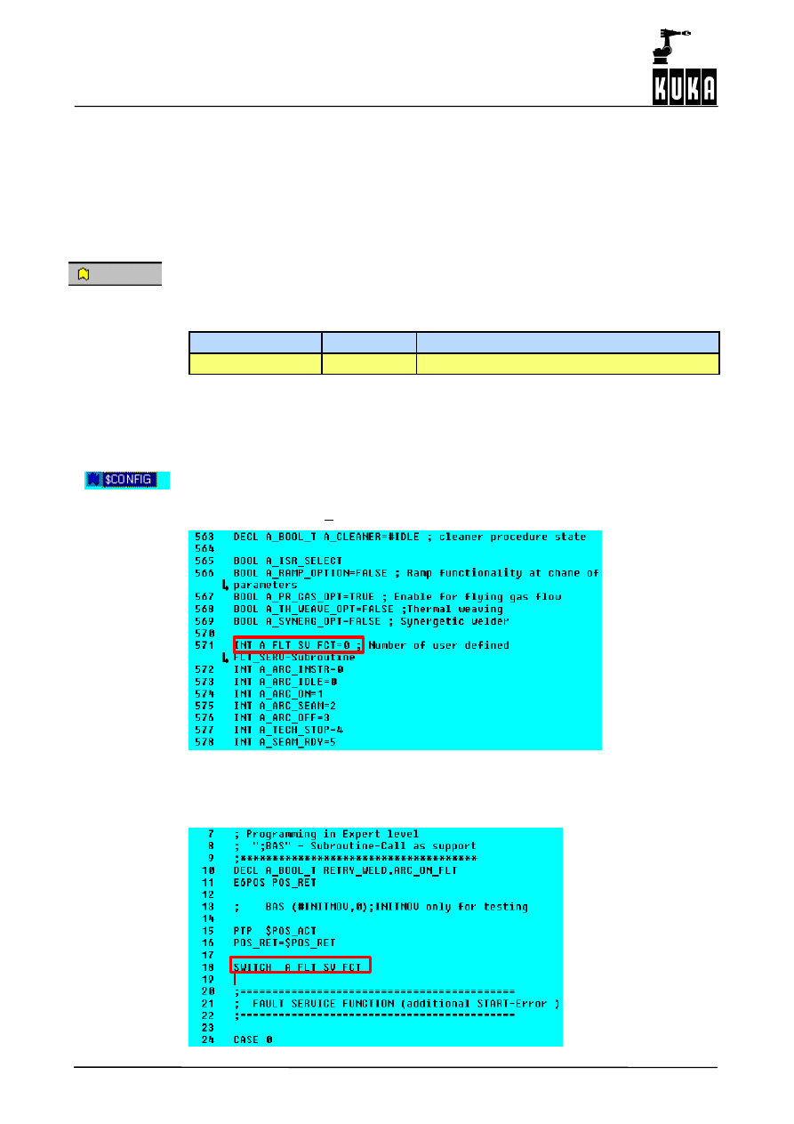
The file “FLT_SERV.SRC” contains a fault service function with the designation “CASE 0”
as well as five other examples (CASE 1 ... 5) that can be freely configured.
The selection of the fault service subroutine to be used is made in the file “$CONFIG.DAT”
by means of the variable “A_FLT_SV_FCT” (default setting: 0):
INT A_FLT_SV_FCT=0 ; Number of user defined FLT_SERV-Subroutine
The entry “A_FLT_SV_FCT=0” corresponds to the subroutine “CASE 0” in the file
“FLT_SERV.SRC”. This procedure is suitable, for instance, for cutting through insulating
oxide layers (for example during aluminum welding) when the wire contacts the workpiece
in order to allow a fault--free ignition process in a restart.
A20.DAT
9
Enumeration of the signal groups for fault service functions
51 of 68
ArcTechDig_P_R23 04.07.00 en
9
Enumeration of the signal groups for fault service functions
If a welding or robot fault occurs during ignition or welding, the process is interrupted. Due
to the variety of causes and types of faults, different fault service subroutines are required.
In addition to the standard measures included in the technology package, the user can
configure his own fault service subroutines tailored to specific requirements.
The descriptions and information in this chapter require the error--free installation, commis-
sioning and configuration of the robot and the hardware and software of the robot controller,
the proper functioning of all peripheral equipment (welding controller, bus systems, etc.)
according to their specifications, and correct programming and parameter settings.
9.1
Types of faults and causes
A distinction is made between application--specific seam faults caused by peripheral
equipment (ignition faults, path faults), and faults attributable to the robot controller
(e.g. IR_STOPMESS faults).
The possible causes of faults may be, for example:
G
Ignition and seam faults resulting from unreliable operating states of the torch and/or
welding equipment;
G
Ignition and seam faults resulting from workpiece characteristics (e.g. oxidation);
G
Media faults (e.g. shielding gas, welding wire, cooling);
G
Controller faults (e.g. IR_STOPMESS faults, EMERGENCY STOP actuation);
G
Operator control function “Interpreter STOP”.
9.2
Ignition faults
9.2.1
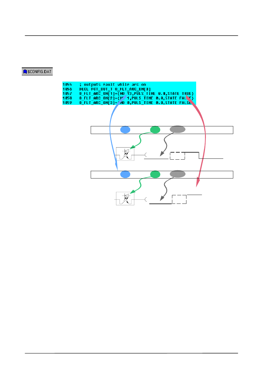
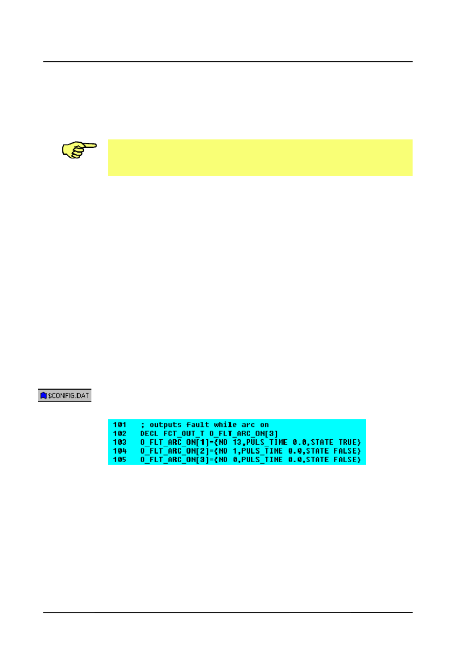
Signal output group O_FLT_ARC_ON[ ]
If the “Arc struck” signal (I_START_MOVE[ ]) is missing after a weld start, welding is
switched off and an ignition fault signal is set. The following signal table is used for this
purpose:
9.3
Welding faults and robot faults
9.3.1
Reaction to robot faults, EMERGENCY STOP and DRIVES OFF
The EMERGENCY STOP and DRIVES OFF states are monitored by means of the system
variable “$STOPMESS”. Normally “$STOPMESS=FALSE”. In the case of “$STOP-
MESS=TRUE”, an interrupt call is made within A20.SRC for the programs “IR_STOPMESS”
or “TECH_STOP1”.
When this state occurs, the welding process or torch cleaning station is switched off. For this
purpose, the corresponding outputs must be defined in the signal tables “O_FLT_WELD[ ]”
and “O_FLT_CLEAN[ ]”. See also Sections 9.3.2 and 9.3.3.
ArcTechDigital 2.3
52 of 68
ArcTechDig_P_R23 04.07.00 en
9.3.2
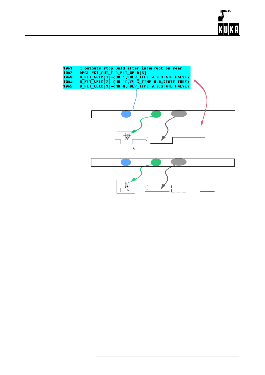
Signal output group O_FLT_WELD[ ]
Welding is stopped if a seam error is detected or an interrupt function is triggered. The signal
table for this reads as follows:
9.3.3
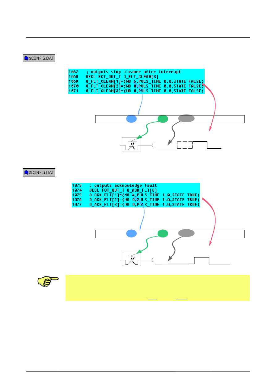
Signal output group O_FLT_CLEAN[ ]
The torch cleaning process is switched off if interrupt functions are triggered. The following
signal table must be taken into account with regard to the torch cleaning device:
9.3.4
Signal output group O_ACK_FLT [ ]
These output signals are used to reset the outputs for torch cleaning.
The ignition fault output can additionally be reset here.
O_ACK_FLT[2] = {NO 13,PULS_TIME 0.0,STATE FALSE}
9.3.5
Signal O_FLT_SIGNAL
This output signal is reset when the corresponding fault has been acknowledged. This refer-
ence manages general fault signals to the PLC.
9
Enumeration of the signal groups for fault service functions (continued)
53 of 68
ArcTechDig_P_R23 04.07.00 en
9.3.6
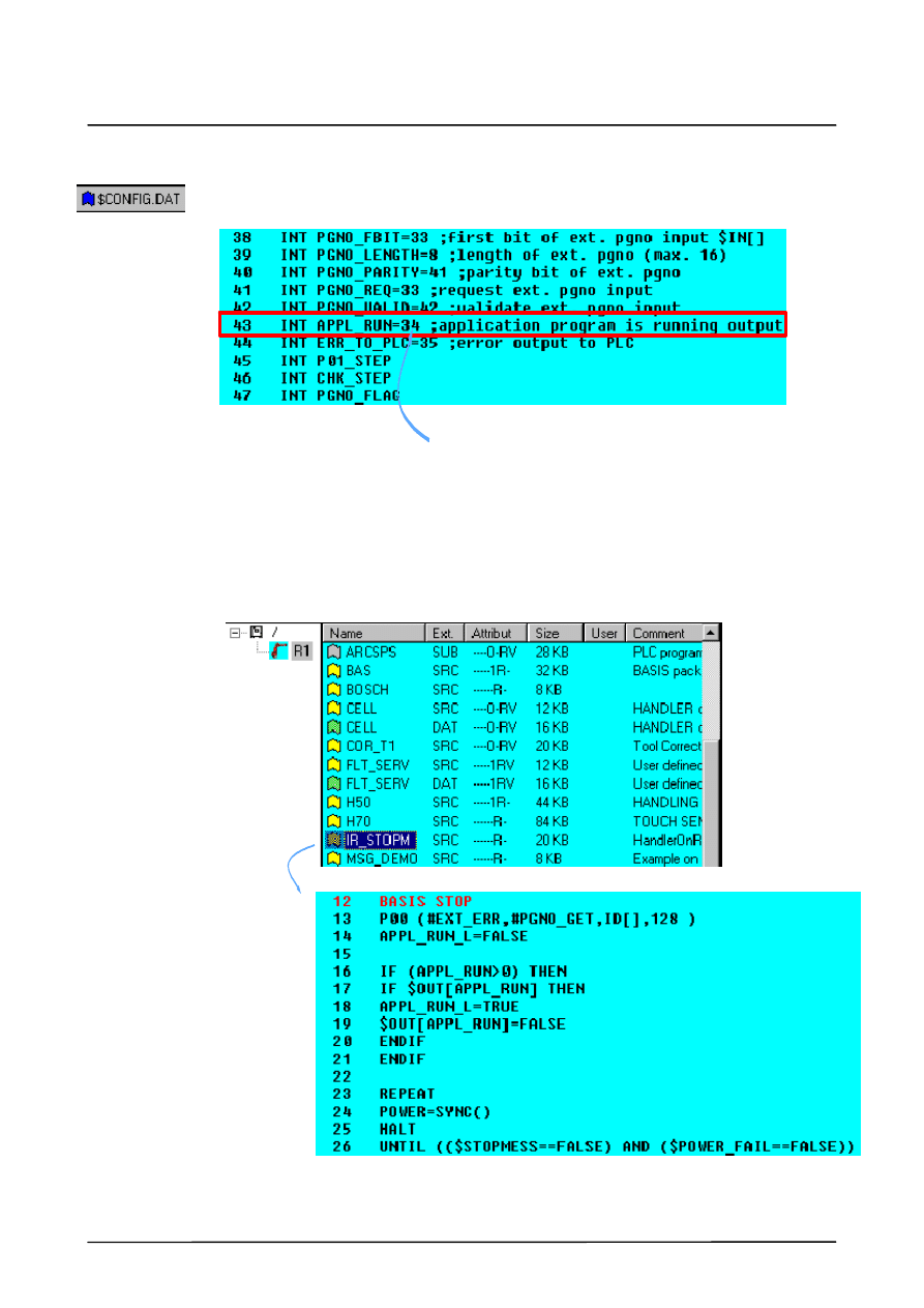
Signal APPL_RUN
This output signal is defined and configured in the Fold AUTOEXT Globals. The signal state
is managed exclusively in the IR_STROPMESS program.
Default $OUT [34]
9.4
Special feature IR_STOPMESS program
9.4.1
Joint activation/deactivation routines
All technologies are deactivated. The interrupt program is subsequently located in the Fold
BASIS_STOP in the IR_STOPM.SRC file.
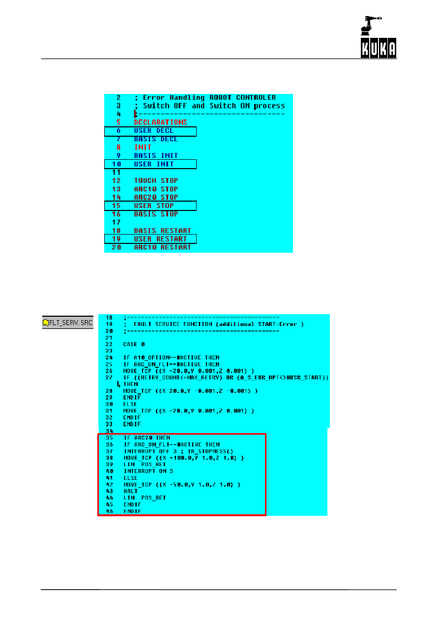
ArcTechDigital 2.3
54 of 68
ArcTechDig_P_R23 04.07.00 en
Once the causes have been eliminated, the technologies are switched back on again one
after the other.
The user must integrate his applications into the
USER blocks in order to avoid impairing other
technologies.
Opened Folds:
9.5
Configurable fault service functions
9.5.1
Fault service functions defined by the user
If ignition is not successful, the
welding torch is moved back by
X=100 mm.
Program continuation: the torch is
moved back by X=50 mm.
Torch is returned to its start position.
10
Further options
55 of 68
ArcTechDig_P_R23 04.07.00 en
10
Further options
10.1
Program test in manual mode
For testing programs in manual mode “T1” under real welding conditions, the variable
“PROC_IN_T1” (default value = FALSE) in the block
;FOLD BAS GLOBALS
;%{E}%V2.3.0,%MKUKATPBASIS,%CGLOBALS,%VGLOBALS,%P
in the file “$CONFIG.DAT” can be set to TRUE.
BOOL PROC_IN_T1=FALSE
Corresponding entry using the menu function “Monitor -- Variable -- Modify”:
Variable
Type
Characteristics
PROC_IN_T1
BOOL Default: FALSE
If a hot welding attempt is made with the setting FALSE, the message “Welding in operation
mode T1 impossible!” appears in the message window.
10.2
Ignition fault message suppression option
Default = 0
The ignition fault messages are suppressed if the condition START_CNT< MAX_AUTO_R
is met and AUTO_RETRY = 1.
If AUTO_RETRY = 0, an error message appears in the message window after every ignition
fault.
10.3
Seam monitoring delay option
A_CTRL_DELAY= 800 [ms] means that the seam monitoring begins after a delay of 800 ms.
This command can be used to optimize the ignition process reliability and always force an
active edge for the seam fault monitoring interrupt. Monitoring is carried out using $TIMER[1]
and $CYCFLAG[3].
This time can be increased if ignition faults occur too often following an unstable ignition
process.

ArcTechDigital 2.3
56 of 68
ArcTechDig_P_R23 04.07.00 en
11
Mechanical weaving
Mechanical weaving is used, for example, to compensate for tolerances or to bridge gaps
in a seam. The torch moves across the seam in this instance and the weave oscillation is
thus superposed on the seam motion. It is also possible to rotate the torch in relation to the
plane of the weld (direction of welding).
Mechanical weaving is executed in the coordinate system “TTS” (tool--based technological
system). In this way, the weaving function is independent of the position of the torch in
relation to the seam and of the torch angle, and irrespective of whether welding is by the
“pushing” or “dragging” technique.
11.1
Block selection response
If a block selection is made to a motion command other than ARC_SWI or ARC_OFF,
mechanical weaving is switched off. In the event of a weld command, the corresponding weld
data set with its weave parameters is taken into consideration. This ensures the continuous
monitoring of the torch motion to the component when moving in Test mode.
11
Mechanical weaving (continued)
57 of 68
ArcTechDig_P_R23 04.07.00 en
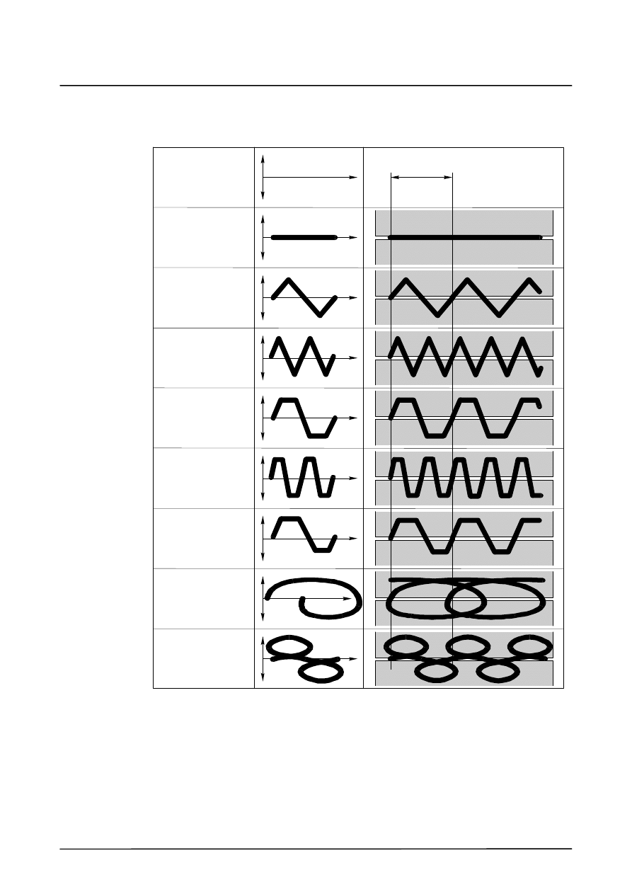
11.2
Weave patterns
The following weave patterns are included in the ArcTechDigital package:
No weaving
(No Weave)
(Triangle)
Triangular
double frequency
(Dbl Triangle)
(Sgl Trapec)
double frequency
(Dbl Trapec)
unsymmetrical
(Uns Trapec)
(Spiral)
(Double 8)
Weave length
Lateral deflection
(amplitude)
Direction of welding
s
s
Trapezoidal
weaving
Trapezoidal
weaving
weaving
Triangular
weaving
Trapezoidal
weaving
Spiral weaving
Figure--of--eight
weaving
ArcTechDigital 2.3
58 of 68
ArcTechDig_P_R23 04.07.00 en
These weave patterns are defined in the file “Weav_def_d.src”.
DEF
WEAV_DEF (GENERATOR :IN,FIGUR :IN )
...
CASE 1 ;triangle
Triangular weaving (SGL_TRI)
CASE 2 ;double triangle
Triangular weaving,
double frequency (DBL_TRI)
CASE 3 ;trapezoid
Trapezoidal weaving (SGL_TRP)
CASE 4 ;double trapezoid
Trapezoidal weaving,
double frequency (DBL_TRP)
CASE 5 ;unsymmetrical trapezoid
Trapezoidal weaving, unsymmetrical
(UNSYM_TRP)
CASE 6 ;spiral
Spiral weaving (SPIRAL)
CASE 7 ;eight
Figure--of--eight weaving (DBL_8)
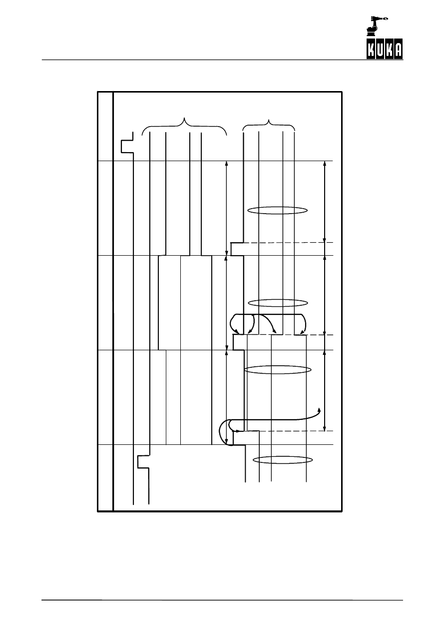
The “Triangle” weave pattern (SGL_TRI) is described in the following example; on the left
is the entry taken from the file “Weav_def_d.src”, and on the right is the assignment to the
individual control points (1 ... 4) with the corresponding X and Y values.
1
--1
0.0
0.25
0.5
0.75
1.0 X
Y
2
1
=
n
3
4
Weav_def_d.src
SWITCH
FIGUR
CASE 1 ;triangle
IF FG_NR1>0 THEN
$TECH[FG_NR1].FCT.ORDER=1
$TECH[FG_NR1].FCT.CPNUM=4
$TECH[FG_NR1].FCT.CPS1.X1=0.0
$TECH[FG_NR1].FCT.CPS1.Y1=0.0
$TECH[FG_NR1].FCT.CPS1.X2=0.25
$TECH[FG_NR1].FCT.CPS1.Y2=1.0
$TECH[FG_NR1].FCT.CPS1.X3=0.75
$TECH[FG_NR1].FCT.CPS1.Y3=-1.0
$TECH[FG_NR1].FCT.CPS1.X4=1.0
$TECH[FG_NR1].FCT.CPS1.Y4=0.0
ENDIF
control points (CPNUM)
The value for X can be between 0.0 and 1.0. Xn=1.0 corresponds to the weave length entered
in the W--parameter list 2 (Mechanical Weaving), i.e. the length over which a pattern is
executed.
The value for Y can be between --1.0 and 1.0. Yn=1.0 corresponds to the lateral deflection
(weave amplitude -- zero to peak) entered in the W--parameter list 2 (Mechanical Weaving).
The weave length X, the lateral deflection Y and the angle of the torch in relation to the
welding plane (weave angle) can be programmed for each weave pattern in the
W--parameter list 2 “Mechanical Weaving” with menu prompting.
Additional information on menu--guided programming can be found in the documentation
[Arc Welding, ArcTechDigital -- Operation].
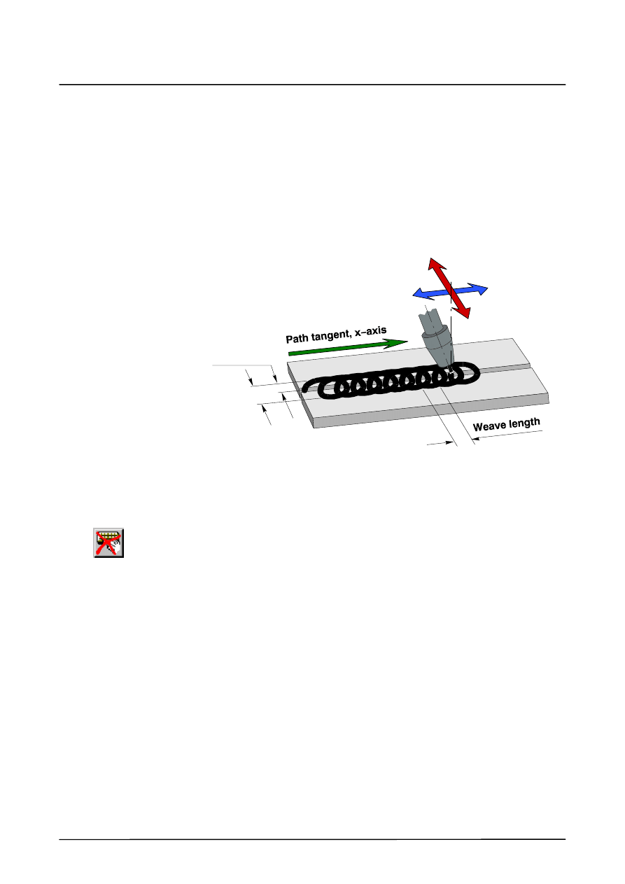
11
Mechanical weaving (continued)
59 of 68
ArcTechDig_P_R23 04.07.00 en
11.2.1 Two--dimensional weaving
Weave patterns such as triangular and trapezoidal patterns result from the lateral deflection
of the torch during motion along the seam. Complex patterns are possible by means of a
second function generator that causes the torch to weave in the welding direction (X--axis).
Two practical functions (for thin sheet welding, for example), namely spiral weaving and
figure--of--eight weaving, are already included in the technology package. You can also
develop your own patterns. The following diagram illustrates the mode of operation of the
function generator using the example of spiral weaving.
(--Y’)
(Y’)
(--Y)
(Y)
Lateral deflection (amplitude) 1)
Deflection in direction of path 2)
Lateral
deflection
(amplitude) 1)
Weave width
Torch
1) Lateral deflection (amplitude) = half weave width
2) Deflection in direction of path= ¦ weave length
$TECH[FG_NR1].FCT.CPS1.Xn=x (0.0 ... 1.0)
$TECH[FG_NR1].FCT.CPS1.Yn=x (0.0 ... 1.0)
Weav_def_d.src
$TECH[FG_NR2].FCT.CPS1.Xn=x (0.0 ... 1.0)
$TECH[FG_NR2].FCT.CPS1.Yn=x (0.0 ... 1.0)
The ratio of the deflection in the welding direction (...FCTCTRL.SCALE_IN) to the weave
length (A.WEAVLEN_MECH) is 1:1. The lateral deflection (...FCTRL.SCALE_OUT)
corresponds to the value set for half the weave width (A.WEAVAMP_MECH).
$TECH[N].FCTCTRL.SCALE_IN=1
$TECH[N].FCTCTRL.SCALE_OUT=1
The “Weave amplitude” value is defined as “zero to peak”, i.e. it corresponds to half the
weave width (peak to peak).
The magnitude of the deflection in the welding direction (...FCTCTRL.SCALE_IN) in relation
to the weave length (W.WEAVLEN_MECH) is set in the file “A20.SRC” at a ratio of 1:1. The
lateral deflection (...FCTRL.SCALE_OUT) corresponds to the value set for the half weave
width (W.WEAVAMP_MECH).
11.2.2 Creating the “Spiral” weave pattern
The following illustration depicts the development of the “Spiral” weave pattern. As a result
of the superposition of a lateral weave motion “sin(x)” with an orthogonally--acting weave
motion of the same frequency in the welding direction “cos(x)”, the torch describes a motion
in the form of a circle (with the same amplitude) or of an ellipse (with different amplitudes).
The spiral form results because the torch is moved by the amount of the weave length (from
X=0 to X=1) during one period (360
˚) in the direction of welding.
A20.src
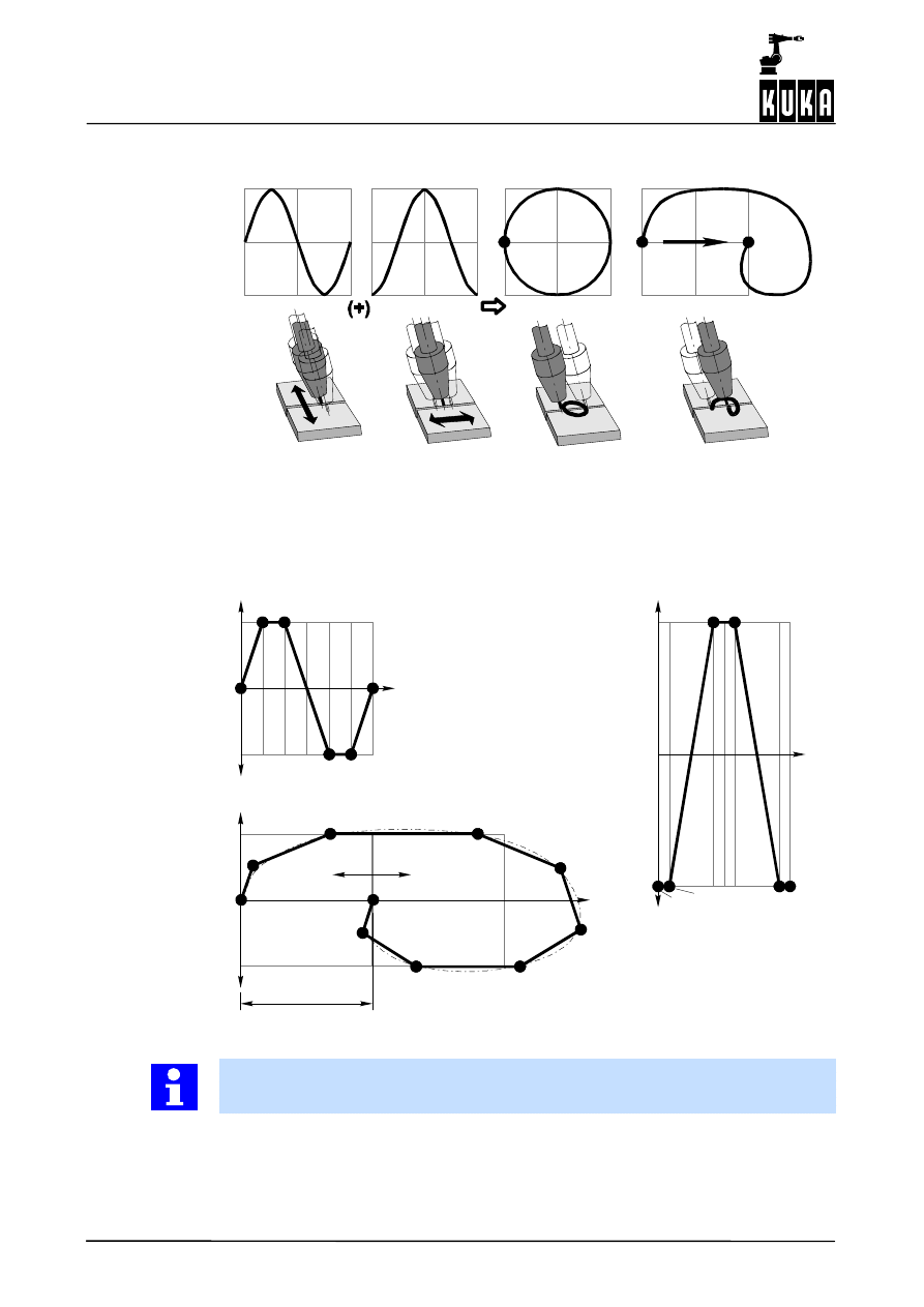
ArcTechDigital 2.3
60 of 68
ArcTechDig_P_R23 04.07.00 en
sin(x)
cos(x)
0
1
0
1
Superposition of cosine on sine
With path
motion
Without path
motion
Welding direction
The following diagram shows the curve shapes of the function generators derived from the
sine function. This is approximately a sine for the lateral deflection (”$TECH[FG_NR1]...”)
and a cosine for the deflection in the direction of the path (”$TECH[FG_NR2]...”). The corre-
sponding control point parameters are stored under “CASE 6 ;spiral” in the file
“Weav_def_d.src”. The figure of a spiral results from the superpositioning of these two mo-
tions.
1’ 2’
3’
4’
5’ 6’
--1
1
Y
0
X
1,0
Y
0
1
2 3
4 5
6
--1
1
X
1,0
1
1’
2’
3
2
6, 6’
3’
4’
5
5’
4
--1
1
Y
0
X
(--Y’)
(Y’)
Deflection in
direction of path
Lateral deflection (amplitude)
Resultant: spiral
Weave length
$TECH[FG_NR1]...
(X 1 ... 6; Y 1 ... 6)
$TECH[FG_NR2]...
(X 1 ... 6; Y 1 ... 6)
The control points for the “Spiral” weave pattern are defined in the file “Weav_def_d.src”.
The parameters for the lateral deflection are stored in the first block (...NR1...).
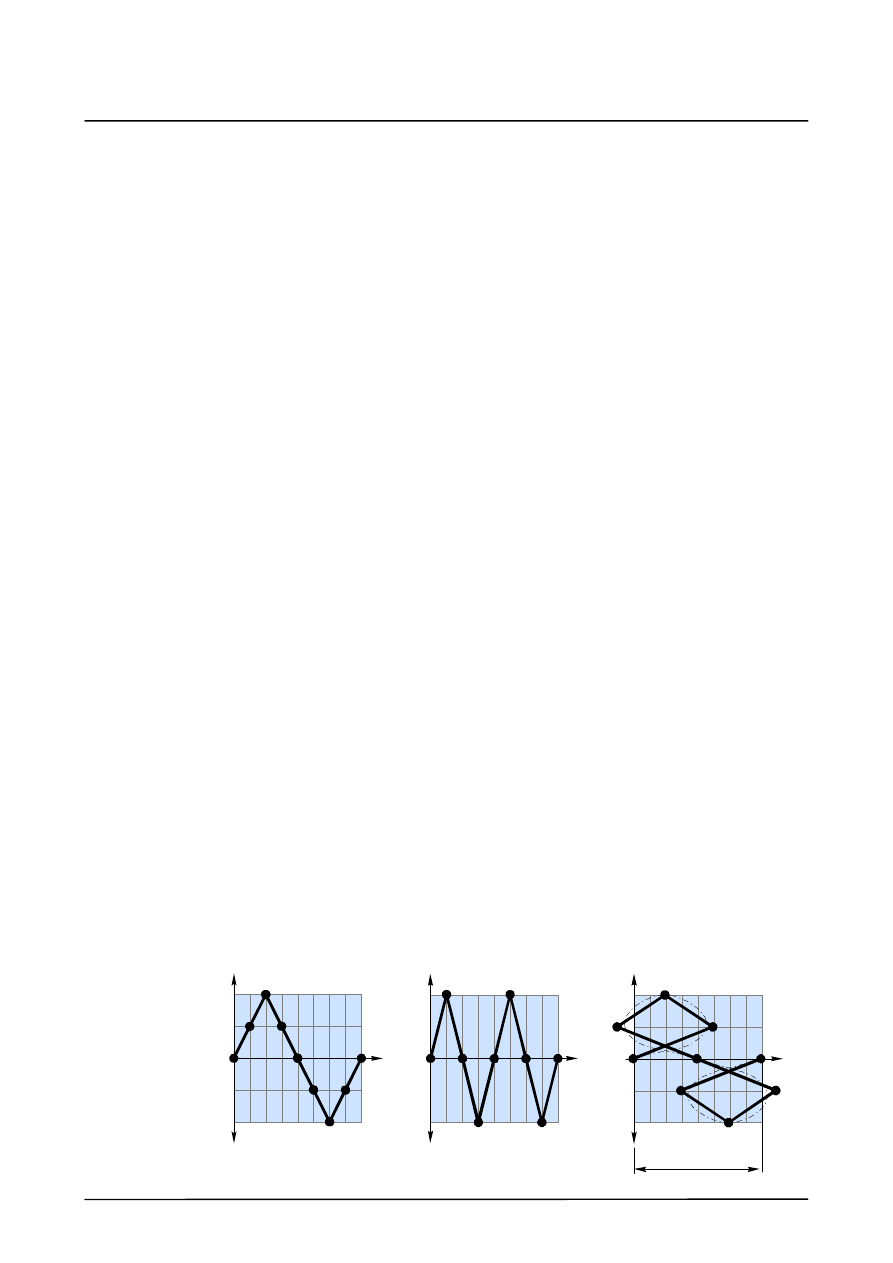
11
Mechanical weaving (continued)
61 of 68
ArcTechDig_P_R23 04.07.00 en
CASE 6 ;spiral
IF FG_NR1>0 THEN
$TECH[FG_NR1].FCT.ORDER=1
$TECH[FG_NR1].FCT.CPNUM=6
$TECH[FG_NR1].FCT.CPS1.X1=0.0
$TECH[FG_NR1].FCT.CPS1.Y1=0.0
$TECH[FG_NR1].FCT.CPS1.X2=0.166666
$TECH[FG_NR1].FCT.CPS1.Y2=1.0
$TECH[FG_NR1].FCT.CPS1.X3=0.333333
$TECH[FG_NR1].FCT.CPS1.Y3=1.0
$TECH[FG_NR1].FCT.CPS1.X4=0.666666
$TECH[FG_NR1].FCT.CPS1.Y4=-1.0
$TECH[FG_NR1].FCT.CPS1.X5=0.833333
$TECH[FG_NR1].FCT.CPS1.Y5=-1.0
$TECH[FG_NR1].FCT.CPS1.X6=1.0
$TECH[FG_NR1].FCT.CPS1.Y6=0.0
ENDIF
The second block (A_FG_MECH2...) contains the parameters for the deflection in the direc-
tion of the path.
IF FG_NR2>0 THEN
$TECH[FG_NR2].FCT.ORDER=1
$TECH[FG_NR2].FCT.CPNUM=6
$TECH[FG_NR2].FCT.CPS1.X1=0.0
$TECH[FG_NR2].FCT.CPS1.Y1=-1.0
$TECH[FG_NR2].FCT.CPS1.X2=0.083333
$TECH[FG_NR2].FCT.CPS1.Y2=-1.0
$TECH[FG_NR2].FCT.CPS1.X3=0.416666
$TECH[FG_NR2].FCT.CPS1.Y3=1.0
$TECH[FG_NR2].FCT.CPS1.X4=0.58
$TECH[FG_NR2].FCT.CPS1.Y4=1.0
$TECH[FG_NR2].FCT.CPS1.X5=0.916666
$TECH[FG_NR2].FCT.CPS1.Y5=-1.0
$TECH[FG_NR2].FCT.CPS1.X6=1.0
$TECH[FG_NR2].FCT.CPS1.Y6=-1.0
ENDIF
11.2.3 “Figure--of--eight” weave pattern
An additional weave pattern, an asymmetrical “figure--of--eight”, is defined in the file
“Weav_def_d.src” under the designation “CASE 7 ;eight”. This pattern results from the
superposition of a lateral weave motion with an orthogonally--acting weave motion in the
direction of welding with double frequency.
0 1
--0,5
0,5
Y
Y
0
X
--1
1
X
--1
1
Y
0
X
2
3
4
5
6
7
8
9
1
2
3
4
5
6
7
8
9
1
2
3
4
5
6
7
8
9
$TECH[FG_NR1]...
(X 1 ... 6; Y 1 ... 6)
$TECH[FG_NR2]...
(X 1 ... 6; Y 1 ... 6)
Lateral deflection
(amplitude)
Deflection in
direction of path
Resultant: “eight”
Weave length
Weav_def_d.src
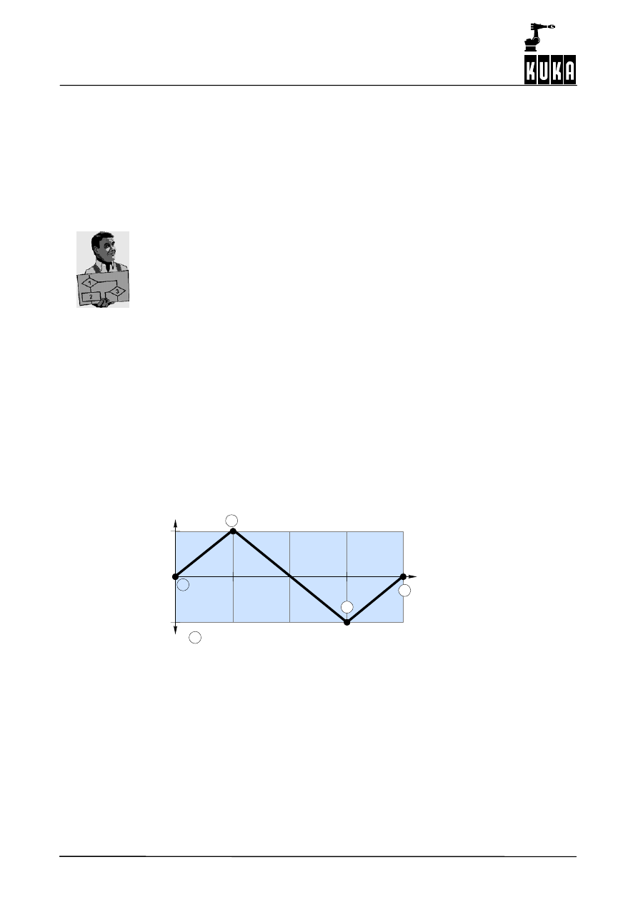
ArcTechDigital 2.3
62 of 68
ArcTechDig_P_R23 04.07.00 en
11.2.4 Changing and creating patterns for mechanical weaving
The weave patterns defined by the manufacturer can be changed by the user, and new
patterns can be created.
11.2.4.1 Changing existing weave patterns
You can adapt the weave patterns defined in the file “Weav_def_d.src” to your own require-
ments by changing the number of control points and their parameters.
You want to shift the “Triangle” pattern -- contained in the file “Weav_def_d.src” -- by 180
˚
in the phase angle.
The settings for the “Triangle” weave pattern are contained in the file “Weav_def_d.src”.
CASE 1 ;triangle
IF FG_NR1>0 THEN
$TECH[FG_NR1].FCT.ORDER=1
$TECH[FG_NR1].FCT.CPNUM=4
$TECH[FG_NR1].FCT.CPS1.X1=0.0
$TECH[FG_NR1].FCT.CPS1.Y1=0.0
$TECH[FG_NR1].FCT.CPS1.X2=0.25
$TECH[FG_NR1].FCT.CPS1.Y2=1.0
$TECH[FG_NR1].FCT.CPS1.X3=0.75
$TECH[FG_NR1].FCT.CPS1.Y3=-1.0
$TECH[FG_NR1].FCT.CPS1.X4=1.0
$TECH[FG_NR1].FCT.CPS1.Y4=0.0
ENDIF
Represented graphically:
1
--1
0.0
0.25
0.5
0.75
1.0
X
Y
2
1
=
n
3
4
control points (CPNUM)
In order to achieve a phase shift of 180
˚, it is merely necessary to change the parameters
for control points Y2 and Y3. The required changes have been made in the following list and
are underlined for ready identification.
Weav_def_d.src
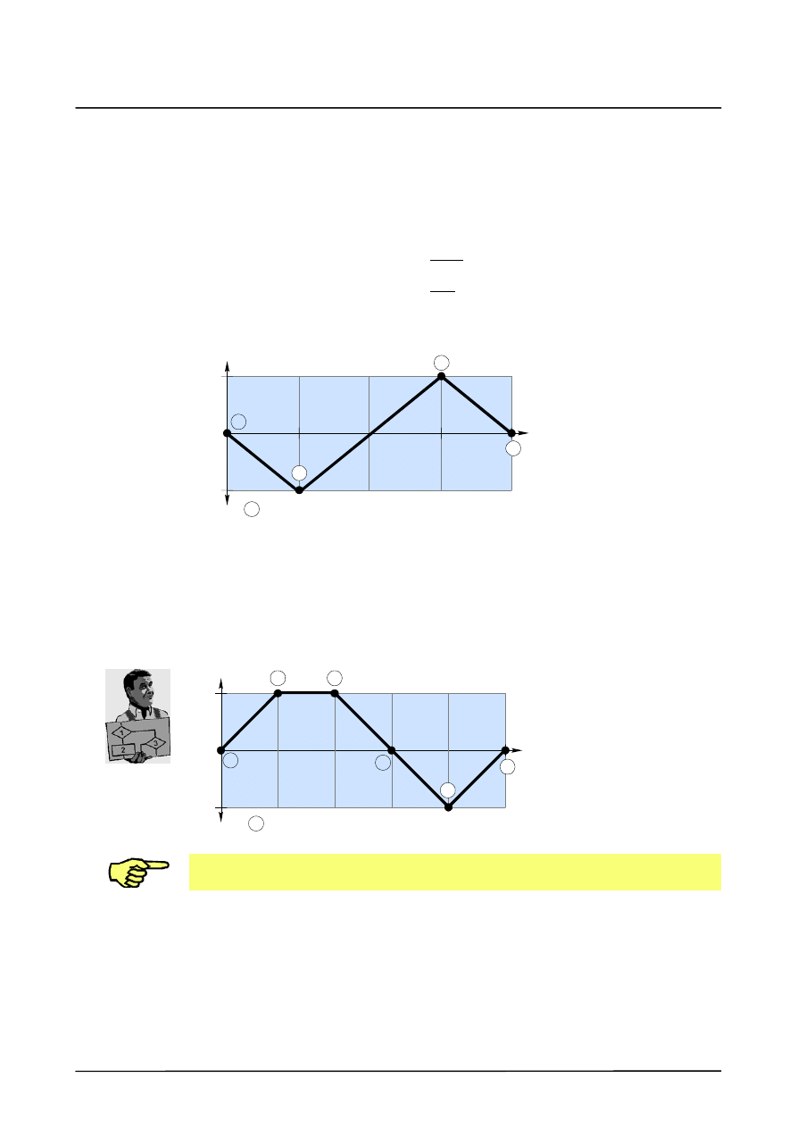
11
Mechanical weaving (continued)
63 of 68
ArcTechDig_P_R23 04.07.00 en
CASE 1 ;triangle (phi = 180 degrees)
IF FG_NR1>0 THEN
$TECH[FG_NR1].FCT.ORDER=1
$TECH[FG_NR1].FCT.CPNUM=4
$TECH[FG_NR1].FCT.CPS1.X1=0.0
$TECH[FG_NR1].FCT.CPS1.Y1=0.0
$TECH[FG_NR1].FCT.CPS1.X2=0.25
$TECH[FG_NR1].FCT.CPS1.Y2=-1.0
$TECH[FG_NR1].FCT.CPS1.X3=0.75
$TECH[FG_NR1].FCT.CPS1.Y3=1.0
$TECH[FG_NR1].FCT.CPS1.X4=1.0
$TECH[FG_NR1].FCT.CPS1.Y4=0.0
ENDIF
1
--1
0.0
0.25
0.5
0.75
1.0
X
Y
1
=
n
3
4
2
control points (CPNUM)
11.2.4.2 Creating your own weave patterns
The following example shows the practical approach for creating your own weave patterns.
A weave pattern is to be created as a combination of a trapezoid and a triangle.
It is recommendable to start by drawing the desired pattern. A range from 0.0 to 1.0 for the
path “X” covered within a period and 1 for the lateral deflection “Y” are predefined.
1
--1
0.0
0.4
X
Y
3
2
=
n
4
1
5
6
0.6
0.2
0.8
1.0
control points (CPNUM)
The first value for X must be 0 (zero) and the last value must be 1. Multiple X values that
are identical cannot be used.
The number of control points determined (CPNUM) as well as the X and Y values can be
entered, for example, in the block “CASE 8 ;default as minimums and flag for beginning” of
the file “Weav_def_d.src”, as shown in the following.
Weav_def_d.src
ArcTechDigital 2.3
64 of 68
ArcTechDig_P_R23 04.07.00 en
CASE 8 ;Trapez - Dreieck
$TECH[A_FG_MECH1].FCT.ORDER=1
$TECH[FG_NR1].FCT.CPNUM=6
Number of control points
$TECH[FG_NR1].FCT.CPS1.X1=.0
Value X for control point 1
$TECH[FG_NR1].FCT.CPS1.Y1=.0
Value X for control point 1
$TECH[FG_NR1].FCT.CPS1.X2=.2
Value X for control point 2
$TECH[FG_NR1].FCT.CPS1.Y2=1.0
Value Y for control point 2
$TECH[FG_NR1].FCT.CPS1.X3=.4
...
$TECH[FG_NR1].FCT.CPS1.Y3=1.0
...
$TECH[FG_NR1].FCT.CPS1.X4=.6
$TECH[FG_NR1].FCT.CPS1.Y4=.0
$TECH[FG_NR1].FCT.CPS1.X5=.8
$TECH[FG_NR1].FCT.CPS1.Y5=-1.0
$TECH[FG_NR1].FCT.CPS1.X6=1.0
$TECH[FG_NR1].FCT.CPS1.Y6=.0
ENDIF
11.2.5 Notes on mechanical weaving
The quality of a seam welded with mechanical weaving is influenced by a variety of physical
and mechanical factors, such as the mechanical play in the gears, axis torsion, robot
position, path tangent, etc. In addition, interdependencies with the interpolation cycle as well
as the set robot--specific $Filter value also exist.
The weave motion is superposed on the path motion. In case of weave patterns such as
“Trapezoid” or “Spiral”, this leads to an irregular welding speed during a period. This can vary
between the set path velocity and a multiple of it, depending on the relation of the weave
length (frequency) to the lateral deflection (amplitude).
The maximum weave frequency for mechanical weaving is – depending on the robot type
concerned – influenced by several factors, for example by the resonant frequency of the
“robot/tool” mechanical unit. Weave frequencies of up to 3 Hz (corresponding, for example,
to a weave length of 3.33 mm at a travel speed of 0.6 m/min) are possible without causing
problems according to previous experience.
With higher weave frequencies, undesirable effects are liable to result in certain conditions
(depending on the tool design and/or tool orientation). With weave frequencies > 3 Hz, the
motion characteristics of the robot should therefore be individually tested in each case.
Weav_def_d.src
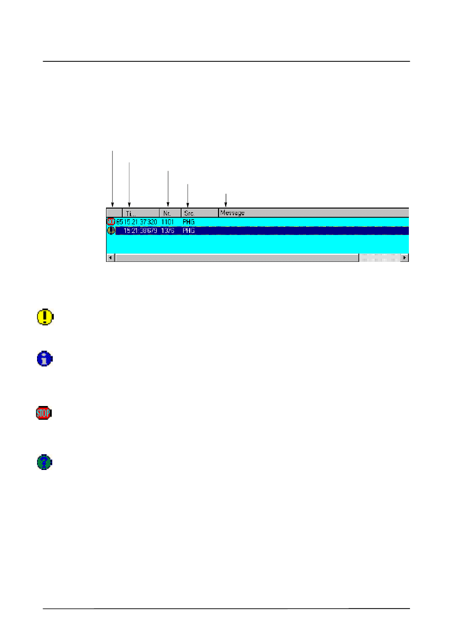
12
Error messages / troubleshooting
65 of 68
ArcTechDig_P_R23 04.07.00 en
12
Error messages / troubleshooting
Messages of all categories are displayed in the message window. These can be either
informative messages that do not need to be acknowledged or messages that have to be
acknowledged.
A message consists of the following items of information, for example:
Message group
Message time
Message number
Originator
Message text
ACTIVE COMMANDS INHIBITED
COMMAND ACCELERATION EXCEEDED A2
12.1
Message groups
Hint messages
provide the operator with explanatory information, for example, if an illegal key has been
pressed.
Operational messages
signal the status of the system that has led to a control reaction, e.g. Emergency Stop. The
message is cleared once its cause has been eliminated. In some cases, a secondary signal
that has to be acknowledged is set for reasons of safety.
Acknowledgement messages
indicate a situation that must in all instances be recognized and acknowledged with the
acknowledge key. They are often a consequence of a status (operational) message. An
acknowledgement message stops a movement or prevents further operation.
Dialog messages
require confirmation by the operator (“Yes” or “No” softkeys). The message is cleared after
it has been confirmed.
12.2
Message time
The message time indicates the time at which the message was generated.
12.3
Message number
With the aid of the message number, the corresponding cause, effect and remedy can quickly
be located in the list of error messages.

ArcTechDigital 2.3
66 of 68
ArcTechDig_P_R23 04.07.00 en
12.4
Originator
The origin of the error is indicated in this field. In the case of ArcTechDigital, the entry is
TPA20.
12.5
Message text
The text of the error message is shown here.
12.6
List of error messages
To make it easier to find error messages in the following list, the message number is shown
first, unlike on the display. By referring to this message number, it is possible to obtain further
information on an error and the appropriate remedial action. This information is subdivided
into:
Message text
is the actual text of the error message as displayed.
Cause
gives a detailed description of the cause of the error.
Monitor
indicates when the conditions for generation of the message are checked.
Effect
describes how the controller reacts to the error.
Remedy
describes what action the user can take to eliminate the error.
12 Error messages / troubleshooting (continued)
67 of 68
ArcTechDig_P_R23 04.07.00 en
1
Message text
Option bit ARC20 not set
Cause
-- ARC20 = FALSE
Monitor
-- In ARC ON command
Effect
-- Endless loop always with this message
Remedy
-- Set ARC20 to TRUE, stop and restart Submit interpreter, data backup
2
Message text
Submit is not running
Cause
-- Submit interpreter has been stopped, etc.
Monitor
-- In ARC ON command
Effect
-- Endless loop always with this message
Remedy
-- Restart Submit interpreter
3
Message text
Wrong submit routine selected
Cause
-- No SPS.SUB submit program running while ARC20=TRUE
Monitor
-- During initialization of A20_INIT commands
Effect
-- Endless loop with this message, as deactivation not otherwise
possible in event of interpreter stop
Remedy
-- $PRO_I_O[ ] = “R1/SPS ( )”
4
Message text
Weld controller not ready
Cause
-- The inputs configured in the signal input group I_WELD_COND [ ]
are missing when welding is activated
-- Position of the keyswitch (incorrect status for welding)
Monitor
-- In ARC ON command
Effect
-- Endless loop with this message
Remedy
-- Move the keyswitch to the correct position
-- Switch on power source (I_WELD_COND [ ])
5
Message text
Ignition failure, no arc
Cause
-- Configured signals not returned to input group I_START_MOVE [ ]
Current flow not established
Power source sends this output too late or not at all
Weld current connections broken
Monitor
-- ARC_ON command
Effect
-- Ignition process is cancelled and restarted, once message
acknowledged, in accordance with configured option and number of
ignition attempts set
Remedy
-- For test purposes or start--up, the I_START_MOVE [ ] condition may
be deactivated
ArcTechDigital 2.3
68 of 68
ArcTechDig_P_R23 04.07.00 en
6
Message text
Continue without welding
Cause
-- Too many ignition attempts; too many seam faults or interruption
with RESTART_OPT = 0 (continue “Cold”)
Monitor
-- In ARC ON command
Effect
-- Seam not welded
Remedy
-- Clean ignition position and make new block selection to ARC_ON
position
7
Message text
Switch off welding
Cause
-- Power source does not switch welding off or does so too late
-- Incorrect configuration
-- Incorrect burnback parameters
Monitor
-- In ARC OFF command
Effect
-- Single message for user
Remedy
-- Optimization of the burnback parameters
8
Message text
Weld controller fault
Cause
-- Periphery error: robot waiting for the inputs expected in
I_WELD_FLT [ ]. Normally configured as current flow “Gas present”,
coolant monitoring
-- Configuration error (OK state configured)
Monitor
-- Continuous between ignition process and ARC_OFF command if
welding
Effect
-- Welding is switched off; weld process is restarted, once message
acknowledged, depending on RESTART_OPTION
Remedy
-- Complete the configuration
Reconnect gas, water, etc. or check respective sensor
9
Message text
Welding in operation mode T1 impossible!
Cause
-- T1 mode and PROC_IN_T1 = FALSE
Monitor
-- In advance run section of ARC ON command
Effect
-- Program remains in this loop after message acknowledged
Remedy
-- Set the above variable to TRUE ($config.dat)
1

Index
Index -- i
Zeichen
$CONFIG.DAT, 29
$Config.dat, 19, 20
$STOPMESS, 51
A
A.WEAVAMP_MECH, 59
A.WEAVLEN_MECH, 59
A_FLT_SV_FCT, 50
A10.SRC, 59
A20.dat, 21
A20.src, 21
Activating, 23
Adaptation to the periphery, 29
ARC OFF, 13, 14
ARC ON, 11, 12
ARC SWITCH, 15, 16
ARC20, 23
B
Basic settings, 23
Block selection response, 56
C
Changing existing weave patterns, 62
Control points (CPNUM), 58
Coordinate system ”TTS”, 56
Crater filling, 37
Creating your own weave patterns, 63
D
DIGITAL INPUTS, 32
Digital inputs, 29
Digital inputs (physical), 32
Digital outputs, 23, 29
Digital outputs (physical), 30
Digitale Eingänge, 24
DRIVES OFF, 51
E
EMERGENCY STOP, 51
External keyswitch, 45
F
FAULT SERVICE FUNCTION, 50
Fault service functions, 54
Fault situations and fault service functions, 51
Figure--of--eight weave pattern, 61
Figure--of--eight weaving, 57
Files for ”ARC Tech 20”, 20
Flt_serv_d.dat, 21
Flt_serv_d.src, 21
Fold ARC Messages in A20.dat, 28
Fold ArcTech Inputs in $Config.dat, 24, 32
Fold ArcTech Outputs in $Config.dat, 23, 30
Fold Internal States in A20.dat, 26, 27
Fold Main Options in A20.dat, 25
I
I_ENB_W_EXT.NO, 45
I_ENB_W_EXT.STATE, 45
I_WELD_CTRL[ ], 32
Ignition faults, 51
Ignition repetition, 50
IN_NR, 32
Index table for physical digital inputs, 32
Index table for physical digital outputs, 30
Index tables, 29
Input group I_START_MOVE [ ], 43
Input group I_WELD_COND [ ], 42
Input group I_WELD_END [ ], 43
Input group I_WELD_FLT [ ], 44
Installation, 8
Interpreter stop (STOP key), 49
IR_STOPMESS program, 53
L
Lateral deflection (weave amplitude), 58
M
MAX_AUTO_R, 50
Maximum weave frequency, 64
Mechanical weaving, 56
Minimum configuration, 23, 25
Motion characteristics of the robot, 64
N
NAME_NAT[ ], 30, 32
Notes on mechanical weaving, 64
O

Index
Index -- ii
O_SEAM_END[ ], 37
O_WELD_CTRL[ ], 30
OUT_NR, 30
Output group O_ACK_FLT [ ], 41
Output group O_ACK_START [ ], 36
Output group O_ACK_WELD_E[ ], 38
Output group O_FLT_ARC_ON [ ], 39
Output group O_FLT_CLEAN [ ], 41
Output group O_FLT_WELD [ ], 40
Output group O_SEAM_END [ ], 37
Output group O_STROB_PGNO [ ], 37
Output group O_WELD_START [ ], 35
P
Power source interface, 23
PRG_NO.CODING, 28
PRG_NO.FIRST_BIT, 28
PRG_NO.LENGTH, 28
PRG_NO.PARITY, 28
PRG_ON_MODE, 47
PRG_SWI_MODE, 47
PRGNO_MAX, 47
PRGNO_MIN, 47
PROC_IN_T1, 55
Program number control, 25
Program number specification, 47
Program run mode ”GO”, 11
Program structure, 19
Program test, 55
PULS_TIME, 31
R
Resonant frequency, 64
RESTART_OPT, 49
RESTART_OPTION, 49
S
Schematic sequence diagram ARC OFF, 14
Schematic sequence diagram ARC ON, 12
Schematic sequence diagram ARC SWITCH,
16
Seam error, 52
Signal APPL_RUN, 53
Signal diagram ARC_OFF, 15
Signal diagram ARC_ON, 13
Signal diagram ARC_SWI, 17
Signal flow of the program numbers, 47
Signal grouping in normal operation, 35
Signal O_FLT_SIGNAL, 52
Signal output group O_ACK_FLT [ ], 52
Signal output group O_FLT_CLEAN[ ], 52
Signal output groups for fault service function,
39
Signal tables for digital inputs, 33
Signal tables for digital outputs, 31
Signal tables for digital outputs and inputs, 29
Spiral weave pattern, 59
Spiral weaving, 57
Start welding -- ARC ON, 11
STATE, 31
STOP key, 49
Switching on the welding process, 11
System requirements, 8
T
Time_out, 45
Timing diagram, 48
Trapezoidal weaving, 57
Triangular weaving, 57
Triple groups, 29
Two--dimensional weaving, 59
Types of faults, 51
W
WEAV_DEF.SRC, 58, 62
Weav_def_d.src, 21
Weave length, 58
Weave patterns, 57
Weave patterns, changing of, 62
Weave patterns, creating of, 63
Weaving, 56
Weaving, two--dimensional, 59
Welding a seam in several sections -- ARC
SWITCH, 15
Welding and ending seams -- ARC OFF, 13
Document Outline
- General
- Description of the “ArcTechDigital” commands
- Programs of the ArcTechDigital package
- ArcTechDigital -- basic settings
- Principles of the definable signal table
- Assignment of the signal grouping in normal operation
- Options for program number specification
- Setting the restart options
- Enumeration of the signal groups for fault service functions
- Further options
- Mechanical weaving
- Error messages / troubleshooting
Wyszukiwarka
Podobne podstrony:
FG Update Service Pro EN 1232 3702 3
Instrukce pro platby v RUB EN
Mechanika Plynow Lab, Sitka Pro Nieznany
Budzik Versa wielkość karty kredytowej instrukcja EN
G2 4 PW EN wn Rys 01
Manual Acer TravelMate 2430 US EN
Ćwiczenie 01 EN DI
eci en
BVSOI 3 001 E en
A Biegus projektowanie konctrukcji stalowych wg PN EN 1993 1 1 cz 1
Flavon Active dopping EN
5817 PN EN ISO IV 2007
Pisownia ę ą en em om
Corel Paint Shop Pro X Obrobka zdjec cyfrowych cwiczenia
NS2 lab 4 4 7 en Configure Cisco IOS IPSec using Pre Shared Keys
PN EN 1990 2004 AC Podstawy projektowania konstrukcji poprawka
EN w9 wspolpraca z siecia
więcej podobnych podstron