
LOKALNE SIECI
KOMPUTEROWE
Specyficzne rozwiązania dla sieci LAN
(100VGAnyLAN, IsoEthernet)
100VG-AnyLAN
100VG-AnyLAN was developed by HP as an alternative to CSMA/CD
for newer time-sensitive applications, such as multimedia.
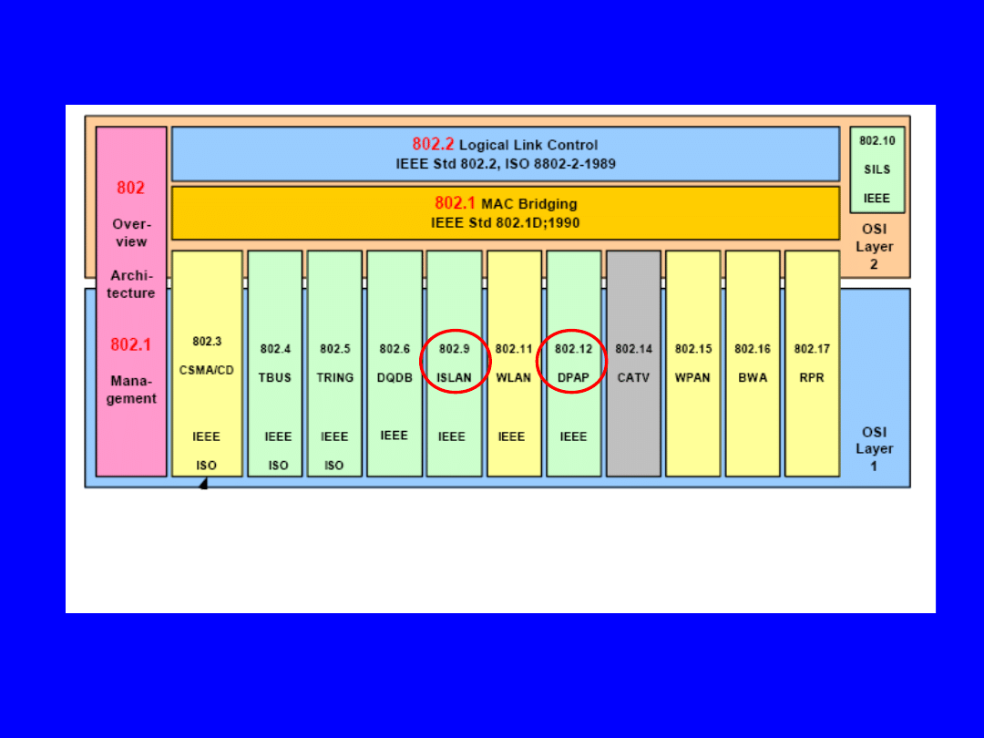
The access method is based on
Demand Prioryty Access Method
and was designed for Ethernet and 16-Mbps Token Ring.
100VG-AnyLAN supports the following cable types:
• 4-pair Category 3 UTP
• 2-pair Category 4 or 5 UTP
• Fiber optic
IEEE 802.12 100VG-AnyLAN standard specifies
the link-distance limitations
,
hub-configuration limitations, and maximum network-distance limitations.
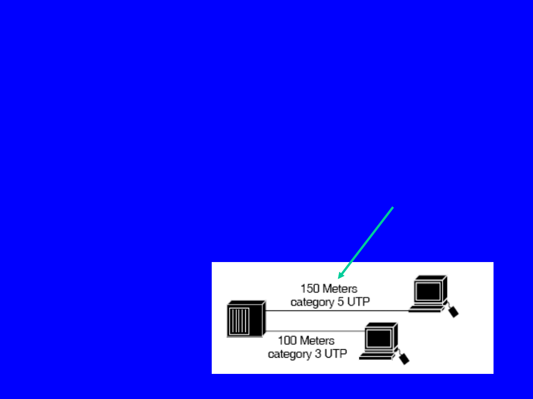
Link distances from node to hub are 100 meters (Category 3 UTP)
or 150 meters (Category 5 UTP).
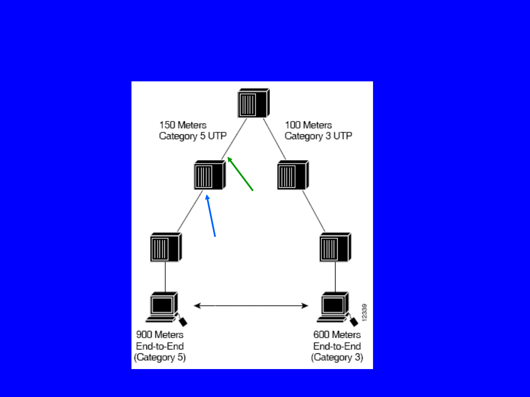
100VG-AnyLAN hubs are arranged hierarchically.
Each hub has at least one
uplink port
, and every other port can be a
downlink port
.
Uplink port
Downlink port
100VG-AnyLAN
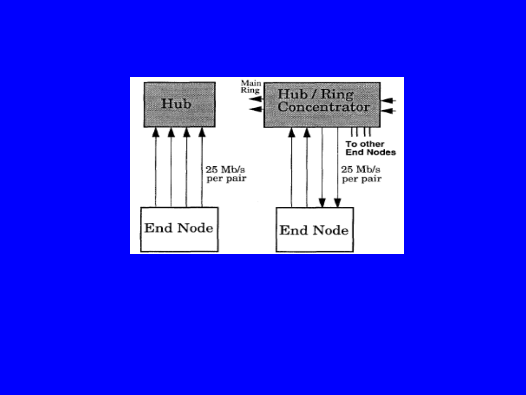
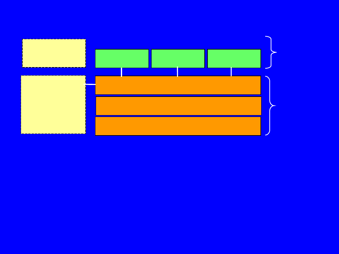
100VG-AnyLAN Operation
Half Duplex Operation
Full Duplex Operation
(e.g. Ring Network)
25 Mb/s per pair
gives 100 Mb/s
25 Mb/s per pair
gives only 50 Mb/s
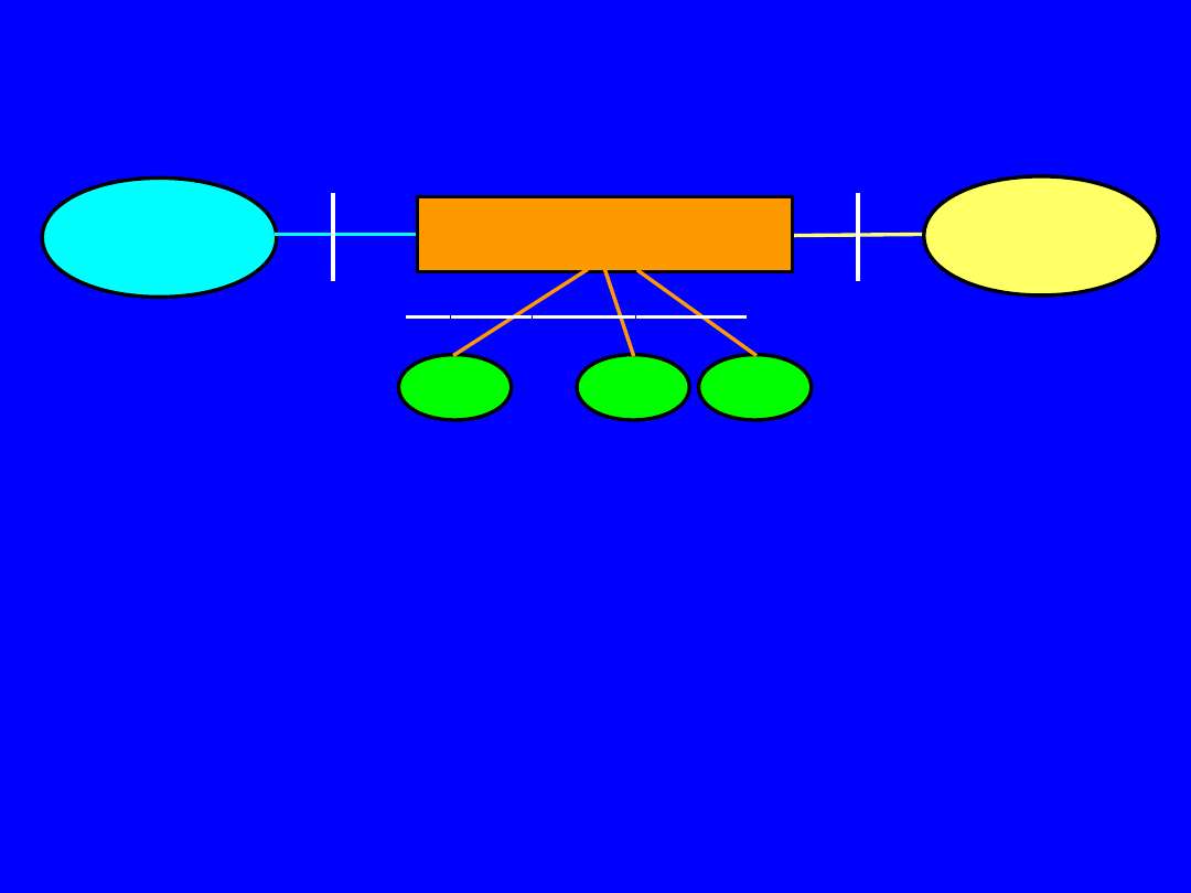
100VG-AnyLAN - Demand Priority Link Protocol
Demand Priority uses a small number of control signals:
- four control signals sent from Hub to End Node,
- four control signals sent from End Node to Hub.
In a 4-pair UTP link, the control signals are implemented as low
frequency tones.
Each of two pairs transmits one of two possible low frequency
tones,
giving four control signals in each direction.
The link has 3 states:
1. Hub is sending a frame at 100 Mb/s to End Node
2. End Node is sending a frame at 100 Mb/s to Hub
3. Hub and End Node are exchanging control signals.
1. 25 Mb/s data
on 4 pairs
2. 25 Mb/s data
on 4 pairs
3. Control signal tones
in both directions
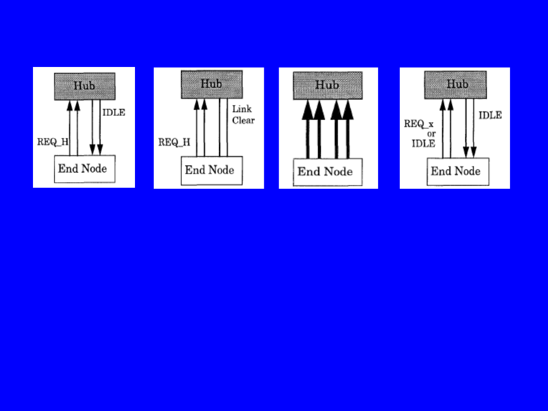
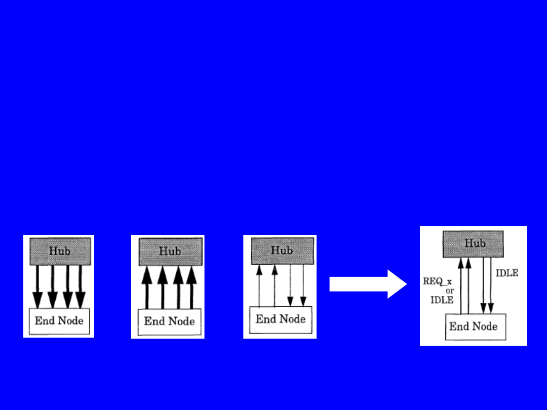
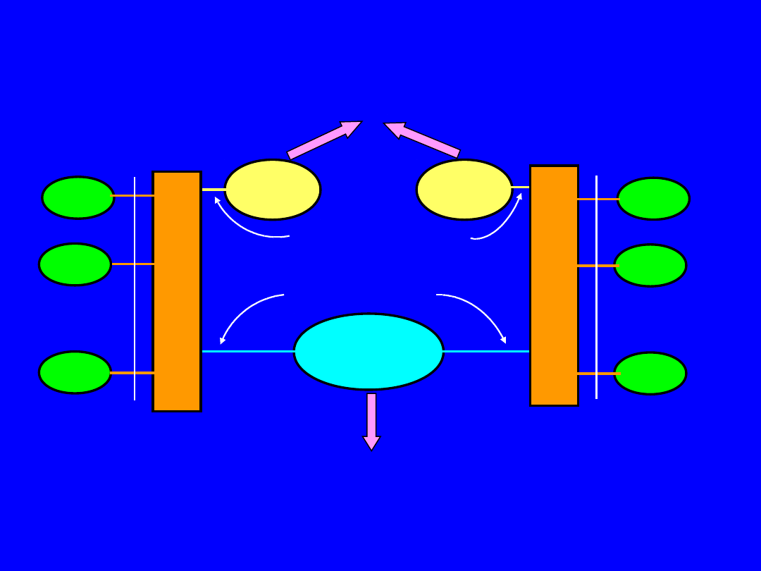
100VG-AnyLAN - Demand Priority Link Protocol
A. Link Protocol Sequence of the End Node
transmitting frame
1. End Node
sends Request
2. Hub clears
link
3. Frame
transmitted at
25 Mbps per pair
4. Control
signals resume
(1) When End Node has a frame to send, it sends up a control signal REQ-H
(High Priority Request)
or REQ-N (Normal Priority Request) to the Hub.
(2) When the Hub decides to select this particular End Node, it stops actively
sending the control signal
on 2 pairs, in effect it clears the link to the End Node.
(3) When the End Node senses that there is no signal on the link, it realises
that it has been selected
to transmit by the Hub. It can transmit immediately on 4 pairs.
(4) When the frame is finished, the Hub will send IDLE,
and the End Node will send REQ-H or REQ-N (depending on the priority
level of further frames
to be transmitted) or IDLE (if there are no such frames).
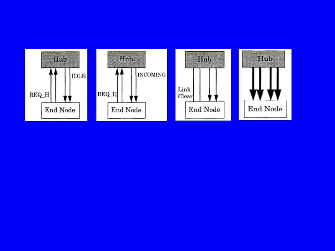
100VG-AnyLAN - Demand Priority Link Protocol
B. Link Protocol Sequence of the End Node
receiving frame
1. Hub and End
Node exchange
control signals
2. Hub sends
INCOMING
3. End Node
clears link
4. Frame
transmitted
at 25 Mbps per pair
(1) The Hub and End Node are exchanging control signals.
(2) The Hub is expecting to receive a frame from some other
End Node.
It sends INCOMING to the End Node.
(3) A short time later, the End Node clears the link.
(4) The link is now clear, so the Hub is able to start sending the
frame on all 4 pairs.
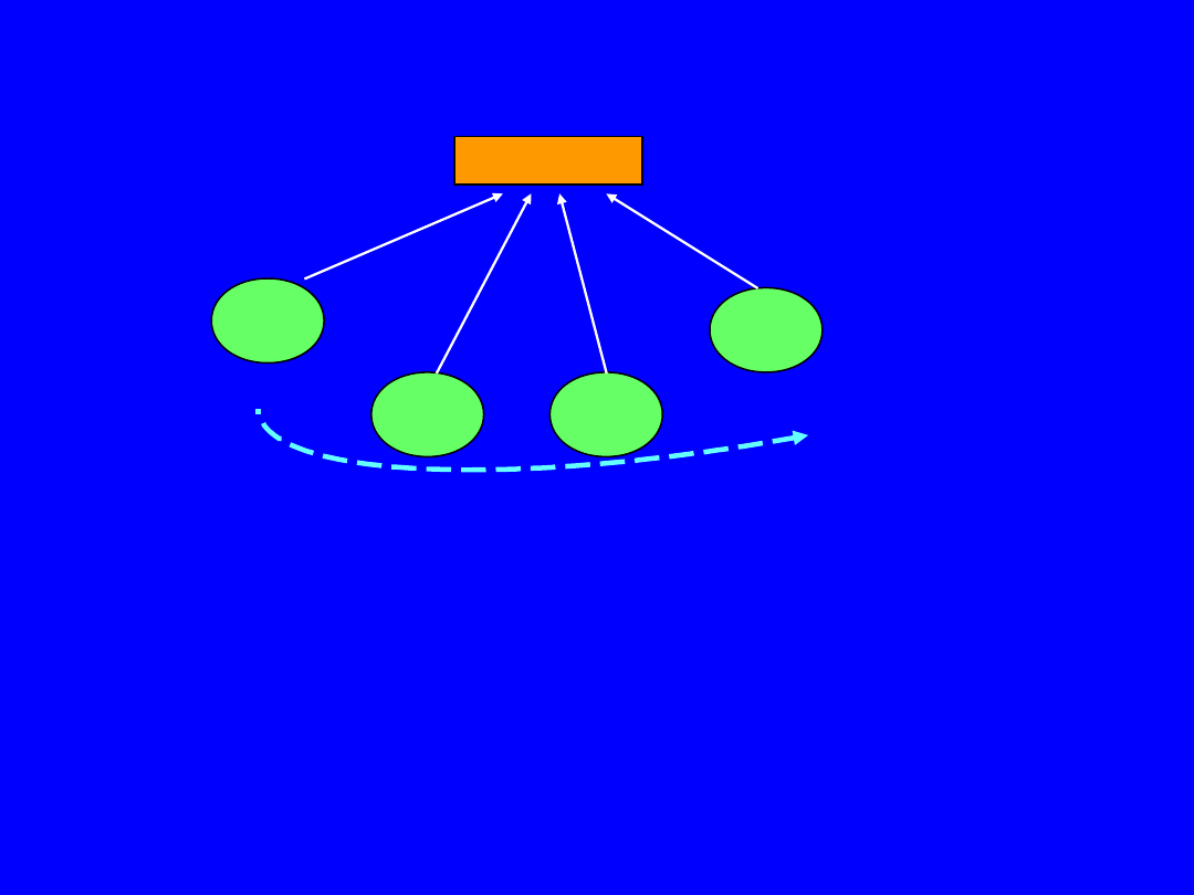
100 VG Any LAN – Round Robin
Demand Priority uses a 2-priority
Round Robin.
The Hub services High Priority Requests before
any Normal Priority Requests are serviced: 1, 3, 2, 4
Hub A
Node 1
Node 2
Node 3
Node 4
REQ_H
REQ_N
REQ_H
REQ_N
Round Robin
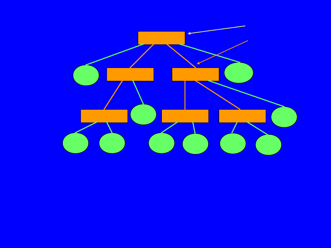
100 VG Any LAN - Cascading of Hubs
The each Demand Priority Hubs have a port acting as
a Cascade port,
which
is connected to the Hub in the next level up.
Each of the Hubs are identical.
A Hub knows that it is
the Root Hub
by the fact that it has no communication
through its Cascade Port.
If all of the Nodes have frames to transmit at the same priority level,
then the order of transmitting frames is the same sequence:
Node 1, then Node 2, Node 3, then Node 4, … up Node 10.
Root Hub
Hub A
Hub D
Hub B
Hub C
Hub E
Hub F
Node3
Node4
Node1
0
Node1
Node2
Node5 Node6
Node7
Node8
Node9
Cascade port
Level III
Level II
Level I

What is Isochronous Ethernet (IsoEthernet)?
When an IsoEthernet-equipped sends Ethernet data traffic,
data goes from the IsoHub/Switch to Ethernet hub
and is handled like all other Ethernet transmissions.
When an IsoEthernet-equipment sends isochronous traffic (e.g. voice, video),
IsoHub/Switch sends data to either a PBX
or to a Time-division Multiplexer (TDM) via E-1 or ISDN PRI/PRA trunk.
The bandwidth, required for a specific video/audio call is allocated end-to-end.
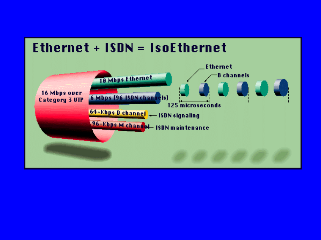
IsoEthernet provides a way to bring both
Ethernet and ISDN
services.
IsoEthernet is an enhancement of Ethernet (10Base-T) that includes:
- 6.144 Mbps isochronous data service
- 10 Mbps Ethernet packet service.

Isochronous Ethernet complies to a lot of standards from ITU and IEEE:
ITU-T recommendation H.320 service over N-ISDN networks
ITU-T recommendation H.322 (H32Z.1) modified H.320 for LANs
which provide the same QOS as that of N-ISDN
ITU-T recommendation H.221 protocol layer, does multiplexing and demultiplexing
ITU-T recommendation G.711/G.722/G.728 audio compression algorithm
ITU-T recommendation H.261 video compression algorithm
ITU-T recommendation H.230/231 and H.242/243 in-band signalling
for exchanging commands and capabilities
ITU-T recommendation T.120 protocols which include support
for file transfers, conference control, etc.
ITU Q.93.i network layer ITU Q.921 data link layer
IEEE 802.9 Integrated Services LAN committee specification IEEE 802.9a
defined the physical Layer of Isochronous Ethernet
IEEE 802.3 Carrier Sense Multiple Access Collision Detection (CSMA/CD) specification
ITU LAPD ISDN-D channel specification
The standards family for IsoEthernet
A multimedia service using IsoEthernet
as the integrated services LAN.
A typical IsoEthernet configuration includes a set of Multimedia End Stations (MM ES)
connected to an Access Unit (AU) in a star configuration.
The network side of the AU offers connections to both ISDN and 10Base-T LAN.
Each end station can simultaneously access:
- ISDN (up to 6.144 Mbps for isochronous traffic using)
- 10Base-T LAN (10 Mbps packet traffic) services
ISD
N
LAN
IsoEthernet AU
MM ES
MM ES MM ES
…
PRI
10Base-T
IsoEthernet Interface (16,144 Mbps)
Voice, video and data services
MM ES – Multimedia End Station
IsoEthemet network configuration
ISD
N
LAN
LAN
Isochronous traffic
Synchr./Asynchr. traffic
MM ES
MM ES
MM ES
…
Is
o
E
th
e
rn
e
t
A
U
Is
o
E
th
e
rn
e
t
A
U
MM ES
MM ES
MM ES
…
IsoEthernet
interface
IsoEthernet
interface
MAN, WAN
MAN, WAN
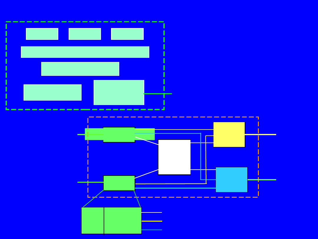
Multimedia End Station and Acces Unit architecture
Video
Audio
Data
IsoEthernet
interface
to IsoEthernet AU
Management
Operational system
H.261/ H.320, T120, …
MM ES
AU
Port #1
Port #N
Packet
switch
Isochr.
switch /
mux.
…
ISDN
LAN
Control
MM ES
MM ES
PMA H-Mux
D, M channel
P channel
C channels
H.261 - video compression algorithm
H.320 - service over N-ISDN networks
T.120 - support for file transfer,
conference control, etc.
IsoEthernet – OSI Model
Physical Layer:
-
HMUX (Hybrid Multiplexing) data from P, C, D and
M – channels,
- PS (Physical Signalling) to 4B/5B coding data,
- PMD (Physical Medium Dependent).
Physical Layer
Link Layer
Management
Sub-Layer Plane
(M-channel)
Management
Layer Plane
Ethernet
P- channel
D – channel /
LAPD
C - channels
HMUX
PS
PMD
…
…
Start P B
B
P
D
D
M
M
…
…
Start P B
B
P
D
D
M
M
…
…
Start P B
B
P
D
D
M
M
0
125
25
0
Time
[s]
Bytes
1
2
3
4
251 252 253 254 255 256
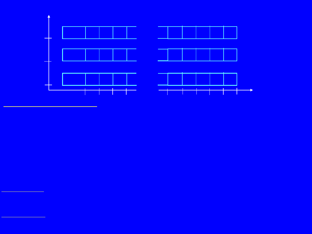
IsoEthernet Frame
Start of Frame Channel:
It carries the start of TDM frame synchronization pattern, which allows the
remote station to detect
the beginning of the TDM frame. It also allows Phase Lock Loops (PLLs) at
the remote end
to synchronize to the incoming frame.
P-channel:
A half or full-duplex 10 Mbps 10BASE-T transport channel for packet traffic.
It obeys the CSMA/CD protocol and is compatible to regular Ethernet.
C-channel:
A full-duplex isochronous circuit-switched channel which offers a multiple of 64 kbps (B-channel) service.
B-channels are provisioned in the same manner as N-ISDN B-channels.
D-channel:
A full-duplex 64 kbps packet channel which is used for transporting call
control and supplementary
Services such as conferencing, call hold, transfer for the C-channel.
M-channel:
A full-duplex 96 kbps channel which transports physical layer control
and status informations
to the remote end of the link.
IsoEthernet – type of channels
The multiple channels are provided through the use of Time Division Multiplexing (TDM).
The information stream is comprised of a continuous sequence of 125 sec (8 KHz)
TDM frames. Each frame consists of up to 256 bytes of information.

10BASE-
T
mode
Muliservice mode
All – isochronous
mode
B /
frame
Data rate
B /
frame
Data rate
P -
channel
10 Mbps
156,5
10 Mbps
-
-
C -
channels
-
96
6,144
Mbps
248
15,872
Mbps
D -
channel
-
1
64 kbps
1
64 kbps
M -
channel
-
1,5
96 kbps
1,5
96 kbps
Overhead
-
1
80 kbps
5,5
352 kbps
Total
-
256
16,384
Mbps
256
16,384
Mbps
Modes of Operation
10BASE-T mode:
The Isochronous Ethernet is fully compatible to to 10Base-T Ethernet. No
TDM frame, no channels.
Multi-service mode:
Both packet and isochronous services are provided. A single 10 Mbps P-channel is dedicated
to the packet traffic, a 6.144 Mbps C-channel (96 B-channels), handles the isochronous services.
A 64 kbps D-channel is used for signalling and a 96 kbps M-channel for maintenance.
Each TDM frame starts with the Start of Frame Channel, which operates at 64 kbps.
All-isochronous mode:
The complete bandwidth is used for circuit-switched isochronous services.
A 15,872 Mbps C-channel (248 B-channels), 64 kbps D-channel, 96 kbps M-channel
and 64 kbps Start of Frame Channel. This mode utilizes the 8 KHz based TDM frame format.
Document Outline
- Slide 1
- Slide 2
- Slide 3
- Slide 4
- Slide 5
- Slide 6
- Slide 7
- Slide 8
- Slide 9
- Slide 10
- Slide 11
- Slide 12
- Slide 13
- Slide 14
- Slide 15
- Slide 16
- Slide 17
- Slide 18
- Slide 19
Wyszukiwarka
Podobne podstrony:
Wirtualne sieci LAN
w8 VLAN oraz IP w sieciach LAN
urzadzenia sieci lan wan
05 LAN Protokol IPid 5733 ppt
Bezpieczeństwo bezprzewodowych sieci LAN
5.1.13 Sieć klient-serwer, 5.1 Okablowanie sieci LAN
lan pracy taktyka - maskowanie, Taktyka
SPRAWKO LSK
,sieci komputerowe,Okablowanie sieci LAN i WAN
projekt sieci LAN z dostępem do Internetu
05 KARTY SIECIOWE SPRZĘTOWE SERCE SIECI LAN
plan pracy-działanie dr lsk na punkcie lsk, wojskowe, Chemiczne
Łan
Instrukcja instalacji sterownika LAN
G LAN ok
harmonogram LSK 2011
cosinus utk 115 karty rozszerzen modem lan tv
Udostępnianie Internetu na drugi komputer w sieci LAN
więcej podobnych podstron