
Technical drawing – Autocad
I,
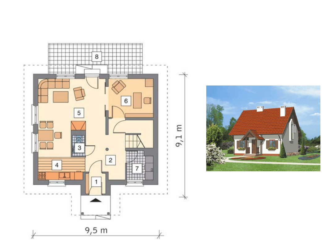
1. GROUND FLOOR PLAN
Joanna Fiszer, Anna Tofiluk.
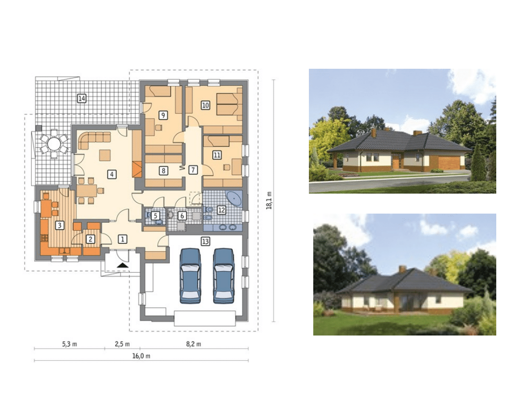
STARTING DATA.
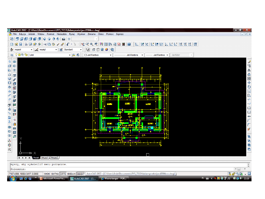
DURING WORKING WITH AUTOCAD
2007.
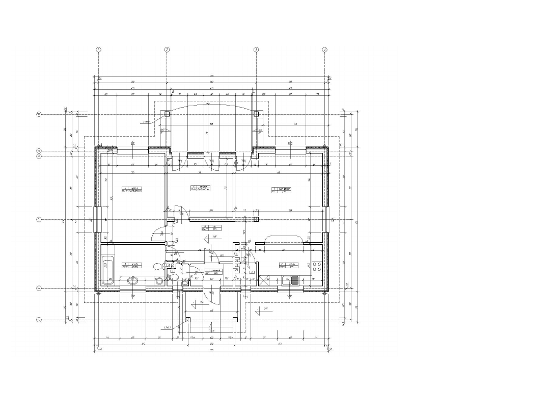
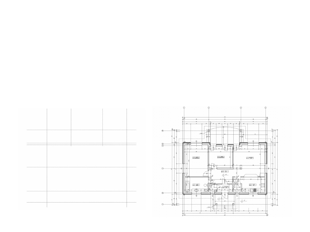
FINAL RESULT.
GROUND PLAN (SCALE 1:100)
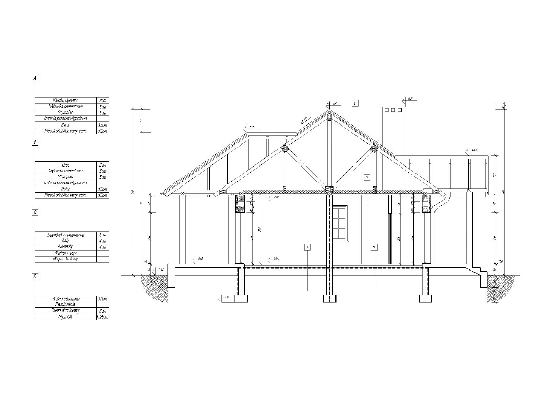
FINAL RESULT.
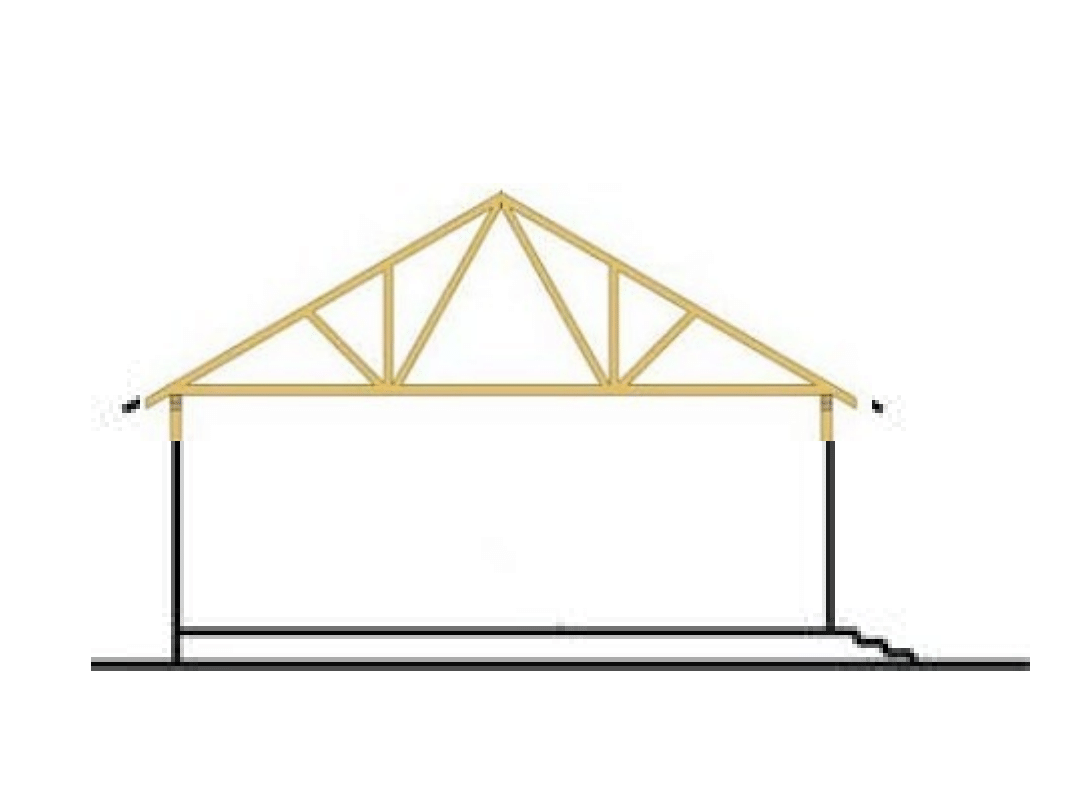
CROSS SECTION (SCALE 1:50)
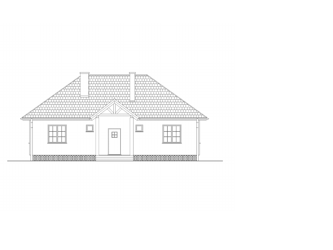
FRONT ELEVATION (SCALE 1:50)
FINAL RESULT.
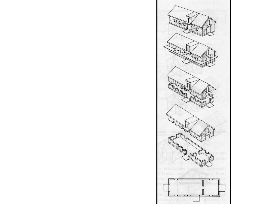
GROUND FLOOR PLAN
–
Horizontal section
through the house on
the ~1,00 m level above
the floor level.
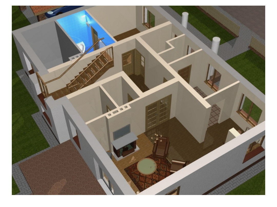
Walls:
• internal walls
• external walls (cavity wall or
double leaf wall, load bearing
wall + heat insulation)

Walls:
• load-bearing walls
• walls supporting the weight above,
including a ceiling and second floor or
roof
• all external walls + 1 or 2 (?)
internal, load-bearing part 25cm +
12cm styrofoam (heat insulation)
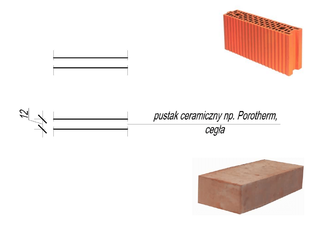
• partition walls, nonbearing walls
• internal walls supporting no load
other than their own weight, they are
present merely to separate space into
multiple rooms
• 12cm.
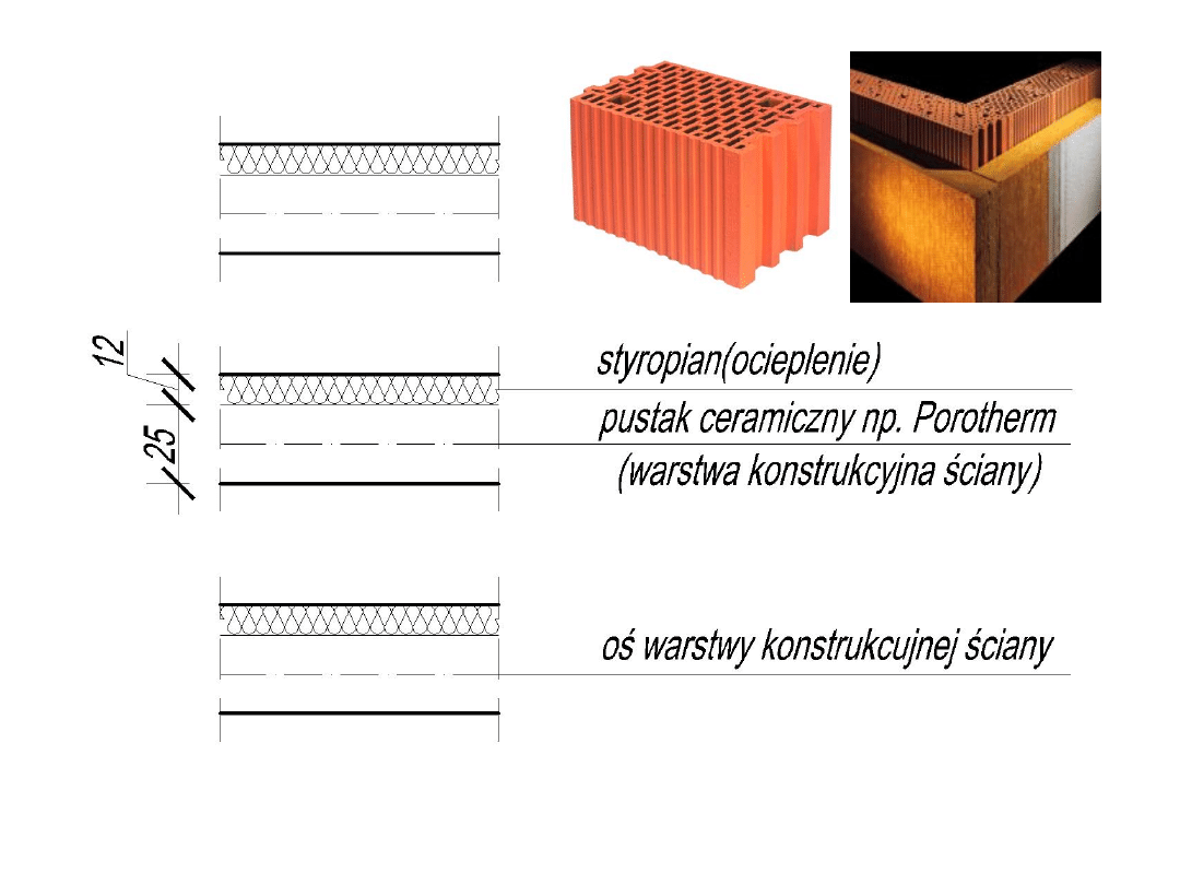
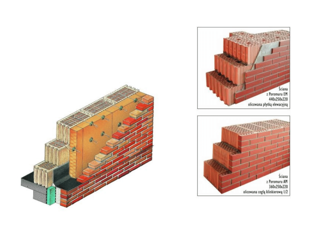
EXTERNAL LOAD-BEARING WALL
AXIS (only in load-bearing
wall)
Porotherm clay blocks
(load-bearing part of the
wall)
Heat insulation
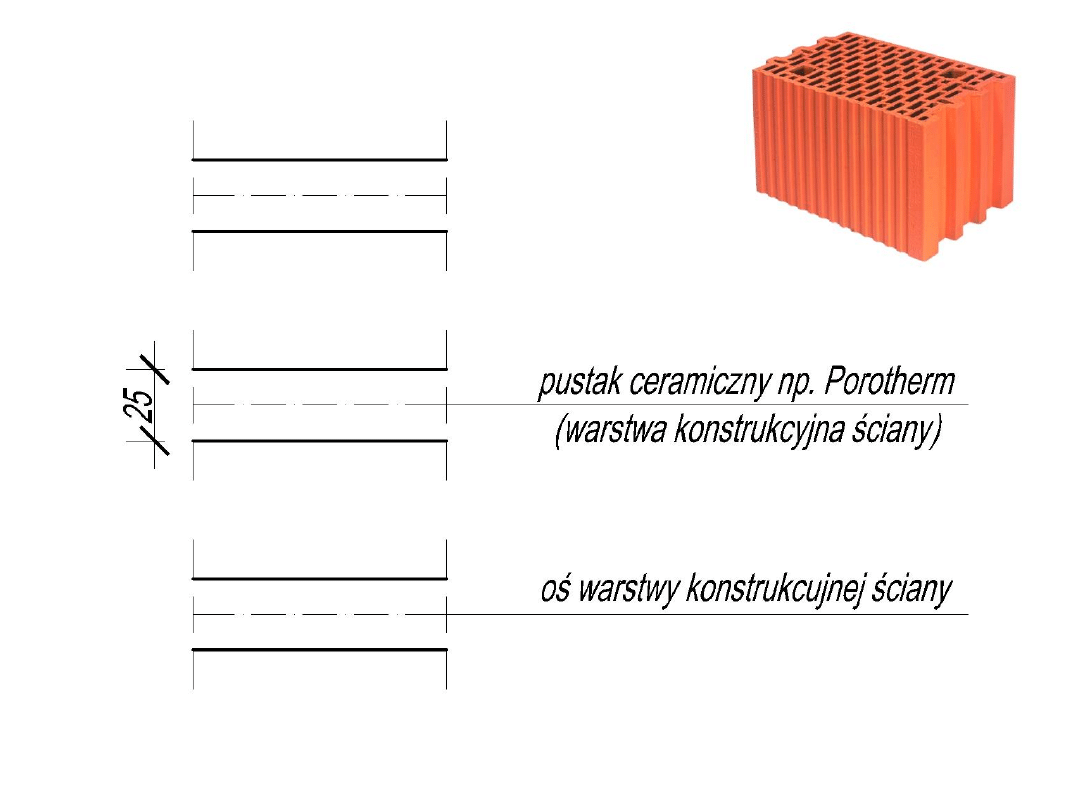
INTERNAL LOAD-BEARING WALL
Porotherm clay blocks
(load-bearing part of the
wall)
AXIS (only in load-bearing
wall)
Porotherm clay blocks,
bricks
PARTITION WALL

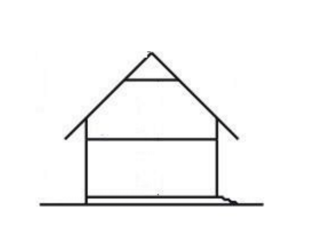
WHICH WALLS ARE LOAD-
BEARING, WHICH ONES ARE
PARTITION WALLS?
It depends on what we got above (if
it’s ceiling or roof structure)
• If ceiling – distance between axises in
load-bearing walls shoul be max.
7,20m – maximum allowable span
• If wooden truss – max. 12m
• If ceiling – distance between axises in load-
bearing walls shoul be max. 7,20m –
maximum allowable span
• If wooden truss – max. 12m
FIRS STEP OF DRAFTING GROUND FLOOR PLAN
IS
DRAWING LOAD-BEARING WALLS’ AXISES
„BUILDING UNIT” = 30cm
Distance between axises in load-bearing walls should be
divisible by 30cm.
- 1,20; 1,50; 1,80; 2,10......5,40......6,00.....7,20
EXAMPLE
Document Outline
- Technical drawing – Autocad I, 1. GROUND FLOOR PLAN
- STARTING DATA.
- DURING WORKING WITH AUTOCAD 2007.
- FINAL RESULT.
- Slide 5
- Slide 6
- Slide 7
- Slide 8
- Slide 9
- Slide 10
- Slide 11
- Slide 12
- Slide 13
- Slide 14
- Slide 15
- Slide 16
- Slide 17
- Slide 18
Wyszukiwarka
Podobne podstrony:
Rysunek techniczny Autocad3 gosia
Rysunek techniczny Autocad1
Rysunek techniczny Autocad2EN
Rysunek techniczny Autocad3
Rysunek techniczny Autocad2
Rysunek techniczny Autocad5
Rysunek techniczny Autocad1ROZSZERZONY
Rysunek techniczny Autocad3EN
Rysunek techniczny Autocad1
Rysunek techniczny Autocad6
Rysunek techniczny Autocad4
Rysunek techniczny 4
więcej podobnych podstron