
imnot50 & suite412
1
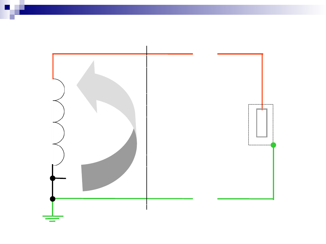
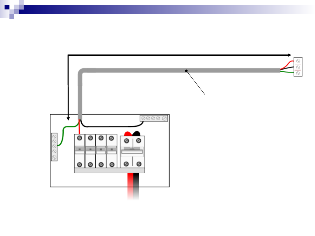
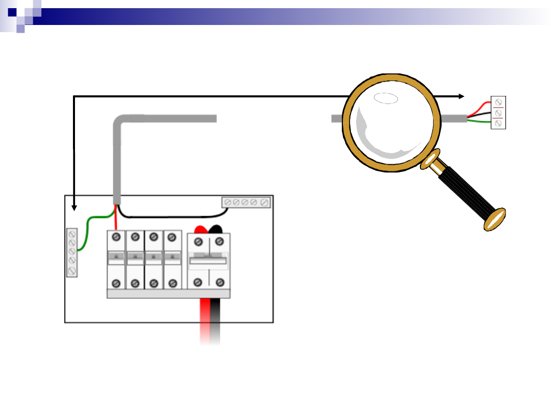
Earthing
Earthing
Calculati
Calculati
ons
ons
imnot50 & suite412
2
Ze
Ze
R
1
R
2
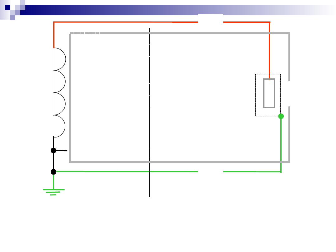
imnot50 & suite412
3
Z
Z
e
R
1
R
2
Z
s
Total Impedance
Total Impedance
Zs = Ze + (R
Zs = Ze + (R
1
1
+R
+R
2
2
)
)

imnot50 & suite412
4
Where:
Ze is the external earth fault
loop impedance
()
Typical values based on a
100A service are:

imnot50 & suite412
5
TN-S system
0.8
0.8
TN-C-S system
0.35
0.35

imnot50 & suite412
6
R1
R1
The resistance of the final
The resistance of the final
circuit phase conductor
circuit phase conductor
R2
R2
The resistance of the final
The resistance of the final
circuit protective conductor
circuit protective conductor
Unit of measurement, the
Unit of measurement, the

imnot50 & suite412
7
Indirect shock calculations
Indirect shock calculations
A circuit is wired in pvc/pvc 70C sheath with
copper
conductors having phase and cpc sizes of
2.5/1.0mm
2
respectively.
The length of circuit is 30 metres and
protection
is by a 20A BS 88 cartridge fuse.
If the value of Ze = 0.7 and disconnection
is to occur
within 0.4 seconds check for indirect shock
protection.
imnot50 & suite412
8
Length of final circuit 30 metres
2.5/1.0mm
2.5/1.0mm
2
2
70
70
C sheath
C sheath
imnot50 & suite412
9
Cross-sectional area
(mm
2)
Resistance/metre
or (R1+R2)/metre
m/m
)
)
Phase
conduct
or
Protecti
ve
conduct
or
Copper
Aluminiu
m
1
1
1.5
1.5
2.5
2.5
2.5
2.5
4
-
1
-
1.5
-
1
1.5
2.5
-
18.10
36.20
12.10
24.2
7.41
25.51
19.51
14.82
4.61
TABLE 1A
TABLE 1A
(Page 107 Guidance Notes 3)
(Page 107 Guidance Notes 3)
Values of resistance for copper and aluminium
Values of resistance for copper and aluminium
conductors and of R1 + R2 at 20ºC in m
conductors and of R1 + R2 at 20ºC in m
/metre
/metre
25.5
1m
25.5
1m
per
met
re
per
met
re
imnot50 & suite412
10
Tot
al R
1 +
R2
=
76
5.3
m
at 2
0C
els
ius
30 metres
30 metres
25.51m
25.51m
per
per
metre
metre
Total R1 + R2 = 25.51 m x 30 metres = 765.3 m
imnot50 & suite412
11
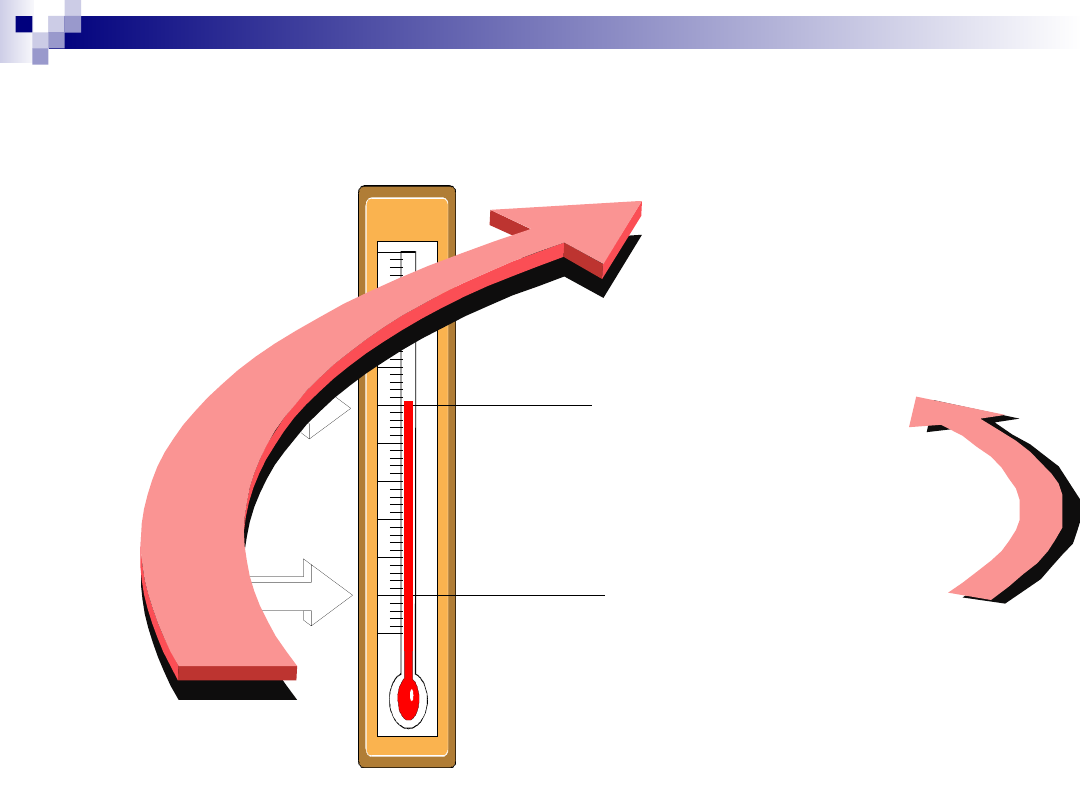
Ambient temperature
Ambient temperature
Heat generated by
Heat generated by
current flow
current flow
Heat produced by
Heat produced by
other circuit conductors
other circuit conductors
Electrical resistance
Electrical resistance
increases with
increases with
temperature rise
temperature rise
imnot50 & suite412
12
20
20
C
C
70
70
C
C
R1 + R2 @ 20C
Multiplied by 1.2 gives
R1 + R2 @ 70C
Increase of resistance with temperature
Increase of resistance with temperature
Remember! Resistance
increases with
temperature rise
imnot50 & suite412
13
Conductor
Conductor
installation
installation
Conductor
Conductor
insulation
insulation
70
70
C
C
pvc
pvc
85
85
C
C
rubber
rubber
90
90
C
C
thermosetting
thermosetting
Not incorporated in a
Not incorporated in a
cable and not bunched
cable and not bunched
- notes 1,3
- notes 1,3
1.04
1.04
1.04
1.04
1.04
1.04
Incorporated in a cable
Incorporated in a cable
or bunched - note 2, 3
or bunched - note 2, 3
1.2
1.2
1.26
1.26
1.28
1.28
Table 1C
Table 1C
(Page 109 Guidance Notes 3)
(Page 109 Guidance Notes 3)
Conductor temperature factors
Conductor temperature factors

imnot50 & suite412
14
Value of R1 + R2 calculated at
Value of R1 + R2 calculated at
20
20
C
C
To allow for temperature rise
To allow for temperature rise
multiply
multiply
by
by
1.2
1.2
Therefore 765.3 m
Therefore 765.3 m
x 1.2 =
x 1.2 =
918.36 m
918.36 m
Convert to ohms (
Convert to ohms (
) = 918.36
) = 918.36
m
m
/1000
/1000
0.918
0.918

imnot50 & suite412
15
Calculating Zs
Calculating Zs
Corrected value of R1+R2
Corrected value of R1+R2
=
=
0.918
0.918
Zs = Ze + (R1 + R2) = 0.7 + 0.918
Zs = Ze + (R1 + R2) = 0.7 + 0.918
=
=
1.618
1.618

imnot50 & suite412
16
Comparing Results
Comparing Results

imnot50 & suite412
17
The calculated value of
The calculated value of
total
total
impedance Zs must not be
impedance Zs must not be
greater than tabulated
greater than tabulated
values in
values in
BS 7671
BS 7671

imnot50 & suite412
18
Maximum permitted values
Maximum permitted values
of Zs
of Zs
41b1 - maximum values of Z
41b1 - maximum values of Z
s
s
for fuses
for fuses
where disconnection is to be within 0.4
where disconnection is to be within 0.4
seconds
seconds
41b2 - maximum values of Z
41b2 - maximum values of Z
s
s
for circuit
for circuit
breakers
breakers
41d - maximum values of Z
41d - maximum values of Z
s
s
for fuses
for fuses
where disconnection is to be within 5.0
where disconnection is to be within 5.0
seconds
seconds

imnot50 & suite412
19
Where to find maximum values of Zs
Where to find maximum values of Zs
Tables 41b1 -
Tables 41b1 -
page 41
page 41
Tables 41b2 -
Tables 41b2 -
page 42
page 42
Tables 41d -
Tables 41d -
page 44
page 44
B
S
B
S
7
6
7
1
7
6
7
1

imnot50 & suite412
20
Table 41 B1
Table 41 B1
(a) General purpose (gG) fuses to BS 88 Parts 2 and 6
(a) General purpose (gG) fuses to BS 88 Parts 2 and 6
Rating 6
Rating 6
10
10
16
16
20
20
25
25
32
32
(amperes
(amperes
)
)
Zs (ohms) 8.89 5.33 2.82 1.85 1.50 1.09
Zs (ohms) 8.89 5.33 2.82 1.85 1.50 1.09
Extract only - Not full table
Extract only - Not full table
Values of Zs for 0.4 seconds disconnection
Values of Zs for 0.4 seconds disconnection

imnot50 & suite412
21
Calculating Zs
Calculating Zs
Corrected value of R1+R2 =
Corrected value of R1+R2 =
0.918
0.918
Zs = Ze + (R1 + R2) = 0.7 + 0.918 =
Zs = Ze + (R1 + R2) = 0.7 + 0.918 =
1.618
1.618
To allow disconnection to be achieved
To allow disconnection to be achieved
within 0.4 seconds the calculated value
within 0.4 seconds the calculated value
must be within the tabulated value
must be within the tabulated value
Tabulated value
Tabulated value
1.85
1.85
Therefore circuit complies
Therefore circuit complies
Greater Than
Greater Than

imnot50 & suite412
22
Disconnection
Disconnection
times
times

imnot50 & suite412
23
Rooms containing a bath tub or shower
Rooms containing a bath tub or shower
0.4 seconds
0.4 seconds
imnot50 & suite412
24
Fixed equipment within the main
Fixed equipment within the main
equipotential zone
equipotential zone
5.0 seconds
5.0 seconds

imnot50 & suite412
25
Fixed equipment outside the main equipotential zone
Fixed equipment outside the main equipotential zone
0.4 Seconds

imnot50 & suite412
26
Socket outlet circuits feeding equipment
located within the main earthed
equipotential zone
0.4 Seconds

imnot50 & suite412
27
Socket outlet circuits feeding portable
equipment intended to be used outside
of the main earthed equipotential zone
Rcd Protected
Document Outline
- Slide 1
- Slide 2
- Slide 3
- Slide 4
- Slide 5
- Slide 6
- Slide 7
- Slide 8
- Slide 9
- Slide 10
- Slide 11
- Slide 12
- Slide 13
- Slide 14
- Slide 15
- Slide 16
- Slide 17
- Slide 18
- Slide 19
- Slide 20
- Slide 21
- Slide 22
- Slide 23
- Slide 24
- Slide 25
- Slide 26
- Slide 27
Wyszukiwarka
Podobne podstrony:
WEEK 7 Earthing Arrangments
advanced calculate perimeter worksheet
Six Week Programme
1 0 Get A Girlfriend In A Week
Ch18 Stress Calculations
PCB track calculation
Multivariable Calculus, cal14
Multivariable Calculus, cal6
Multivariable Calculus, cal19
Dni tygodnia FLASH?YS week
Calculating a Due?te
Turn Off TV Week
1 2 1 Girlfriend in A Week Checklists
Multivariable Calculus, cal2
what is your?vourite?y of the week
04 AC 14 Calculation Guide
Multivariable Calculus, cal16
Popper Two Autonomous Axiom Systems for the Calculus of Probabilities
więcej podobnych podstron