CONSTRUCTION
6 8 • O C T O B E R 2 0 0 6 • E L E C T R O N I C S F O R Y O U
W W W . E F Y M A G . C O M
C
M
Y
K
SUNIL KUMAR
K.S. SANKAR
DIGITAL THERMOMETER-
CUM-CONTROLLER
T
his standalone digital thermom-
eter controls the temperature of
a device according to its re-
quirement. It also displays the tem-
perature on four 7-segment displays
in the range of –55 to +125°C. At the
heart of the circuit is the
microcontroller AT89S8252, which con-
trols all its functions. IC DS1821 is used
as temperature sensor.
IC DS1821
Dallas Semiconductor’s IC DS1821 is
one-degree precision temperature
sensor in a 3-pin pack like a transistor
with single-wire communication
protocol. It can operate as a standalone
thermostat with user-programmable
trip-points (set-point) or as an 8-bit
temperature sensor with a single-wire
digital interface. The open-drain DQ
pin functions as the output for
thermostat operation and as the data
input/output (I/O) pin for single-wire
communications. The single-wire
interface lets user access the non-
volatile memory (EEPROM)
thermostat trip-point registers (TH and
TL), status/configuration register and
temperature register.
When configured as standalone
thermostat, temperature conversions
start immediately at power-on. In this
mode, the DQ pin becomes active
when the temperature of IC DS1821
exceeds the limit programmed into
the TH register, and remains active
until the temperature drops below the
limit programmed into the TL register.
The DS1821 uses Dallas’ exclusive
single-wire bus protocol that imple-
ments bus communica-
tion with one control sig-
nal. This system is ex-
plained in detail in single-
wire bus system section
of the datasheet included in this
month’s EFY-CD.
Temperature sensor
functionality
The core functionality of IC DS1821 is
its proprietary direct-to-digital tem-
perature sensing, which provides 8-bit
(1°C increment) centigrade tempera-
ture readings over the range of –55°C
to +125°C.
This circuit measures the tempera-
ture by counting the number of clock
cycles generated by an oscillator with
a low temperature coefficient during a
gate period determined by a high-tem-
perature-coefficient oscillator.
The low-temperature-coefficient
counter is preset with a base count that
corresponds to –55°C. If the counter
reaches ‘0’ before the gate period is
over, the temperature register, which
is preset to –55°C, is incremented by
one degree, and the counter is again
preset with a starting value determined
by the internal slope accumulator cir-
cuitry of DS1821. The preset counter
value is unique for every temperature
increment and compensates for the
non-linear behaviour of the oscillators
over temperature.
At this time, the counter is clocked
again until it reaches ‘0.’ If the gate
period is not over when the counter
reaches ‘0,’ the temperature register is
incremented again. This process of pre-
setting the counter, counting down to
‘0,’ and incrementing the temperature
register is repeated until the counter
takes less time to reach ‘0’ than the
duration of the gate period of the high-
temperature-coefficient oscillator.
When this iterative process is com-
plete, the value in the temperature reg-
ister will indicate the centigrade tem-
perature of the device.
Operating modes
The DS1821 has two operating modes:
single-wire mode and thermostat
mode. The power-on operating mode
is determined by the user-program-
mable T/R¯ bit in the status/configu-
ration register: if T/R¯ = 0 the device
works in single-wire mode, and if T/
R¯ = 1 the device works in thermostat
mode. The T/R¯ bit is stored in the
non-volatile memory (EEPROM), so it
will retain its value when the device is
powered down.
Single-wire mode.
The DS1821 is
supplied by the manufacturer in
PARTS LIST
Semiconductors:
IC1
- AT89S8252
microcontroller
IC2, IC3
- CD4511 7-segment driver
IC4
- CD4050 non-inverting
buffer
IC5
- DS1821 temperature
sensor
IC6
- 7805 5V regulator
T1
- 2N2222 npn transistor
D1-D5
- 1N4007 rectifier diode
DIS1-DIS4
- Common-cathode,
7-segment display
LED1, LED2
- 5mm light-emitting
diode
Resistors (all ¼-watt, ±5% carbon):
R1-R4
- 10-kilo-ohm
R5-R23,
R25-R28
- 330-ohm
R24
- 5-kilo-ohm
R29
- 1-kilo-ohm
Capacitors:
C1
- 1000µF, 25V electrolytic
C2
- 0.1µF ceramic disk
C3
- 10µF, 16V electrolytic
C4, C5
- 22pF ceramic disk
Miscellaneous:
X1
- 230V primary to 7.5V,
300mA secondary
transformer
S1-S4
- Push-to-on switch
S5
- On/off switch
RL1
- 6V, 150-ohm, 1C/O relay
Configuration Register
DONE
1
NVB
THF*
THL*
T/R
—
*
POL*
1SHOT*
*Store in EEPROM
CONSTRUCTION
7 0 • O C T O B E R 2 0 0 6 • E L E C T R O N I C S F O R Y O U
W W W . E F Y M A G . C O M
C
M
Y
K
single-wire mode (T/
R¯=0). In this mode, the
DQ pin of the DS1821 is
configured as a single-
wire port for communi-
cation with a micropro-
cessor using the proto-
cols described in the
single-wire bus system
section of the datasheet.
These communications
can include reading and
writing the high and low
thermostat trip-point
registers (TH and TL)
and the configuration
register, and reading the
temperature, counter
and slope accumulator
registers. Also in this
mode, the control unit
can initiate and stop
temperature measure-
ments as described in the
operation-measuring
temperature section of
the datasheet.
The TH and TL reg-
isters and certain bits
(THF, TLF, T/R¯, POL
and 1SHOT) in the sta-
tus/configuration regis-
ter are stored in the non-
volatile EEPROM
memory, so these will re-
tain data when the de-
vice is powered down.
This allows these regis-
ters to be
preprogrammed when
the DS1821 is to be used
as a standalone thermo-
stat.
Writing to these non-
volatile registers can take
up to 10 ms. To avoid
data corruption, no write
action to the non-volatile
memory should be initi-
ated while a write to the
non-volatile memory is
in progress. Non-volatile
write status can be moni-
tored by reading the
NVB bit in the status/
configuration register:
If NVB=1, a write to
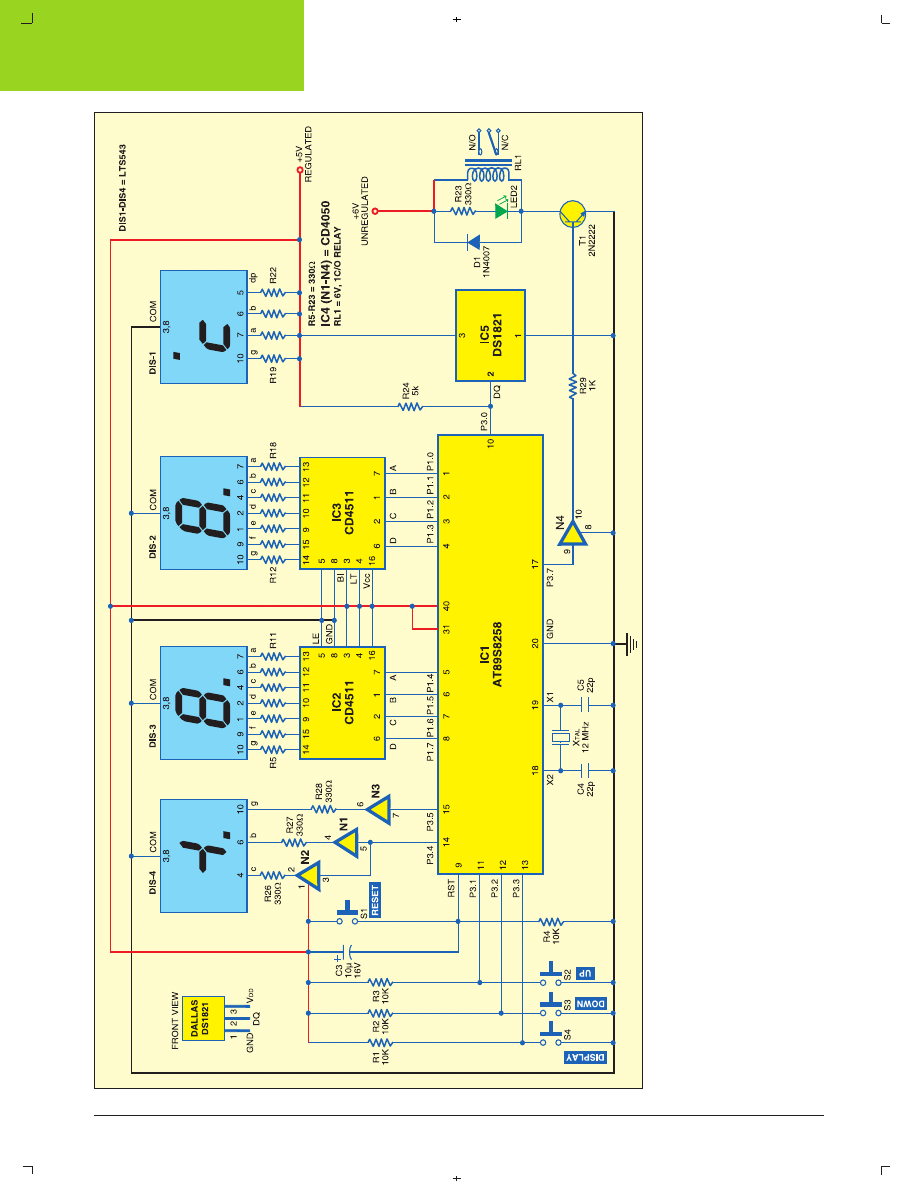
Fig. 1: Circuit of digital thermometer-cum-controller
CONSTRUCTION
7 2 • O C T O B E R 2 0 0 6 • E L E C T R O N I C S F O R Y O U
W W W . E F Y M A G . C O M
C
M
Y
K
EEPROM memory is in progress.
If NVB=0, the non-volatile memory
is in idle state.
Circuit description
Fig. 1 shows the circuit of the tempera-
ture controller using Dallas DS1821.
Microcontroller AT89S8252 is inter-
faced to DS1821 temperature sensor,
three 7-segment displays and relay
RL1. Port P1 of IC1 is used to output
the data on the segment display. Ports
P1.0 through P1.3 and ports P1.4
through P1.7 are connected to IC3 and
IC4, respectively. ICs CD4511 (IC3 and
IC4) receive the BCD data and pro-
vide the compatible code for 7-segment
displays DIS2 and DIS3.
Port pins P3.4 and P3.5 are used
for ‘b,’ ‘c’ and ‘g’ segments of DIS4
through buffers N1, N2 and N3, re-
spectively. Segments ‘b’ and ‘c’ become
active when temperature goes above
99°C. Segment ‘g’ becomes active
when temperature goes below 0°C.
This indicates ‘–’ sign for negative tem-
perature. DIS1 is used in reverse di-
rection for indication of °C. Segments
‘a,’ ‘b,’ ‘g’ and ‘dp’ (decimal point) are
made permanently high with resistors
R19 through R22 to indicate °C.
Port pins P3.1 through P3.3 of IC1
are connected to S2, S3, and S4 switches
for Up, Down and Display, respectively.
These pins are pulled high through a
10-kilo-ohm resistor. Switches S1
through S3 are used for setting/chang-
ing the temperature. When the set tem-
perature is exceeded, the relay con-
nected to port 3.7 through a transistor
is latched on. Switch S1 is used as a
reset switch. Power-on reset is achieved
by capacitor C3 and resistor R4.
Port pin P3.0 of IC1 receives the
data from temperature sensor DS1821.
Pin 17 (P3.7) of IC1 is connected to the
base of transistor T1 through buffer
N4. The signal from port pin P3.7
drives relay RL1. Diode D1 is used as
a free-wheeling diode and LED2 is
used for relay-on indication. The de-
vice is connected through contacts of
RL1. Resistors R5 through R22 limit
the current through the 7-segment dis-
play. A 12MHz crystal is used for
microcontroller clock.
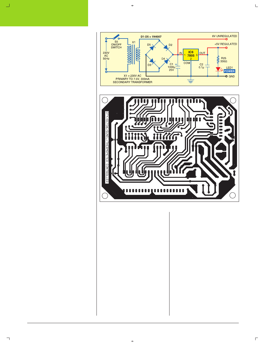
Fig. 2
shows the circuit of power
supply. The AC mains is stepped
down by transformer X1 to
deliver a secondary output of 7.5V at
300 mA. The transformer output is
rectified by a full-wave bridge recti-
fier comprising diodes D2 through D5,
filtered by capacitor C1 and regulated
by IC6. Capacitor C2 bypasses any
ripple present in the regulated out-
put. Regulated 5V is used for circuit
operation and unregulated 6V is used
for relay.
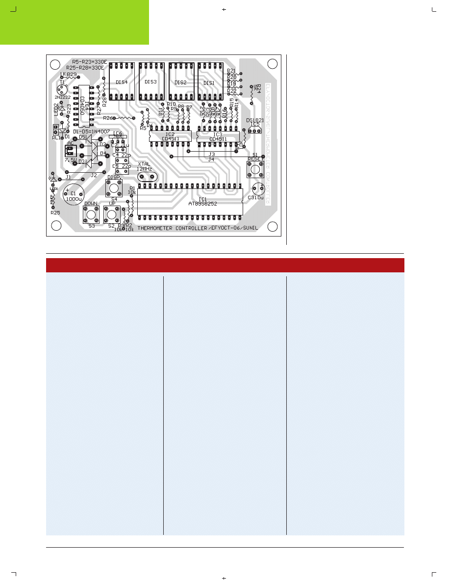
An actual-size, single-side PCB
for temperature controller (Fig. 1)
including its power supply (Fig. 2)
is shown in Fig. 3 and its component
layout in Fig. 4.
The software
The software for the temperature con-
troller is compiled using Bascom51
version. The demo version of Bascom-
8051 is available on website
‘www.mcselec.com/download_8051.
htm.’
First, define the crystal speed and
include the header file for
microcontroller. Initialise all ports to
‘0.’ Timer-0 is used as an internal
counter and increments a variable ev-
ery second. This is used here for timing
delays. Pin P3.0 of the microcontroller
is configured for single-wire commu-
nication. Normal state of DQ pin
(single-wire bus) of DS1821 is high.
Through DQ, the device gets its power
and performs the tasks.
When the microcontroller watches
something happen with single-wire
bus, it issues a reset command. Then
DQ goes low for some time. This re-
sets the device and it sends a pres-
Fig. 2: Power supply
Fig. 3: Actual-size, single-side PCB layout for digital thermometer-cum-controller
CONSTRUCTION
7 4 • O C T O B E R 2 0 0 6 • E L E C T R O N I C S F O R Y O U
W W W . E F Y M A G . C O M
C
M
Y
K
ence pulse and then listens
to the microcontroller. All communi-
cation on the single-wire bus is
initiatised by the microcontroller, and
issued by time slots of active-low on
a normally-high DQ line, issued by
the device, which is sending at the
moment. The internal capacitor of the
device meets its power needs during
the low time.
Declare the variables as bits, bytes
and words. Define the various
port pins and where they are con-
nected. Set the maximum temperature
to ‘40’ as default. Subroutines ‘dispset’
and ‘disptemp’ are used for
display preset and real temperature,
respectively. The source program is
well commented for easy understand-
ing.
EFY note.
Source program,
datasheet and all relevant files are in-
cluded in this month’s EFY-CD.
' tempr.bas 22-8-06
' ds-1821 chip with 12 mhz xtal
' by K.S.Sankar www.mostek.biz for EFY Magazine
' written in embedded basis- Bascom-51
' Language downloaded from http://
www.mcselec.com holland
' p3.0 =data wire
' 1 wire communication with Dallas temperature sen-
sor DS1821
' small PR35 Package, 3 pin , see data sheet for more
details
' Temperatures are in degres when >-1 , <125
' for temperature <0 , 256 - tempdegree will give
' from -55 to -1
' count range
' - - - - - - - - - - -0+++++++++++++
' -55 -54 -3 -2 -1 0 1 2 3 ...125
'201 202 253 254 255 0 1 2 3 ...125
' port p1-yellow
' = two 7seg display thru two 4511 bcd-7decoder ics
' port-p3 blue
' p3.0= 1 wire interface
' p3.1= increase set value
' p3.2= decrease set value
' p3.3= display set value
' p3.4= '1' for hundreds
' p3.5= '-' minus segment for negative
' p3.7= relay out
'define xtal speed
$crystal = 12000000
$regfile = "89s8252.dat"
'select chip used
P1 = 0
P0 = 0
P2 = 0
P3 = 0
'all ports off
P3 = &B01001110
' input port high for switches
' declare function used
Declare Sub Fn7seg(_i As Byte)
TEMPR.BAS
Dim _i As Byte
Config Timer0 = Timer , Gate = Internal , Mode = 2
'Timer0 use timer 0
'Gate = Internal no external interrupt
'Mode = 2 8 bit auto reload
' set t0 internal interrupt 4000 times a sec with 12mhz
xtal
On Timer0 Timer_0_overflow_int
Load Timer0 , 250
Priority Set Timer0
Enable Interrupts
Enable Timer0
' do not start timer0 here
Config 1wire = P3.0
'use P3.0 for 1 wire communication
Dim Sec_count As Byte
Dim Clock_word As Word
Dim I As Byte , J As Byte
Dim Tempdegree As Byte , Stat_buf As Byte ,
Disp_temp As Byte
Dim Settemp As Byte , Set_disp_temp As Byte
Dim Set_mode As Bit
Dim Ans As Byte
Dim Comp_temp As Byte , Comp_set As Byte
Relay_out Alias P3.7
Sw_set_up Alias P3.1
Sw_set_down Alias P3.2
Sw_set_disp Alias P3.3
Sw_in_port Alias P3
Display_port Alias P1
' set default max temperature for relay to activate
Settemp = 40
Set_mode = 0
Begin:
1wreset
1wwrite &H0C
' write status
1wwrite &B01000010
' continue convertion
1wreset
1wwrite &HEE
' start conversion
1wreset
1wwrite &HAA
' get temperature
Tempdegree = 1wread()
1wreset
Gosub Disptemp
'-----------------
Rem check if set keys pressed
' if pressed stay in set loop for 3 seconds
' after inactivity and display will be in flicker mode
Ans = &B01001110 And Sw_in_port
If Ans <> &B01001110 Then
' some input key pressed
Start Timer0
Sec_count = 0
Set_mode = 1
Begin2:
While 1 = 1
If Sec_count >= 3 Then
Set_mode = 0
Exit While
End If
If Sw_set_up = 0 Then
Sec_count = 0
Settemp = Settemp + 1
' - - - - - - - - - - -0+++++++++++++
' -55 -54 -3 -2 -1 0 1 2 3 ...125
'201 202 253 254 255 0 1 2 3 ...125
' plus range
If Settemp <= 200 Then
If Settemp >= 125 Then
Settemp = 125
' limit + reached
End If
End If
End If
'-----------------
If Sw_set_down = 0 Then
Sec_count = 0
Settemp = Settemp - 1
' - - - - - - - - - - -0+++++++++++++
' -55 -54 -3 -2 -1 0 1 2 3 ...125
Fig. 4: Component layout for the PCB in Fig. 3

CONSTRUCTION
7 6 • O C T O B E R 2 0 0 6 • E L E C T R O N I C S F O R Y O U
W W W . E F Y M A G . C O M
C
M
Y
K
'201 202 253 254 255 0 1 2 3 ...125
If Settemp < 201 Then
If Settemp >= 200 Then
Settemp = 201
' (-55 degrees)
' limt exceeded
End If
End If
'-----------------
End If
If Sw_set_disp = 0 Then
Sec_count = 0
End If
'-----------------
Gosub Dispset
Wend
Stop Timer0
End If
' - - - - - - - - - - -0+++++++++++++
' -55 -54 -3 -2 -1 0 1 2 3 ...125
'201 202 253 254 255 0 1 2 3 ...125
' check if real temperature is higher than set value
' add 55 to both sides to avoid negative errors for
comparison
' byte variable does not support (-) values
Comp_temp = Tempdegree + 55
Comp_set = Settemp + 55
''''If Tempdegree >= Settemp Then
If Comp_temp >= Comp_set Then
Relay_out = 1
'relay on
Else
Relay_out = 0
'relay off
End If
Goto Begin
' -==-=-=-=-=-=-=- subroutines below-----
Disptemp:
Disp_temp = Tempdegree
Rem display real temperature
' display on 7 seg
P3.4 = 0
P3.5 = 0
' - - - - - - - - - - -0+++++++++++++
' -55 -54 -3 -2 -1 0 1 2 3 ...125
'201 202 253 254 255 0 1 2 3 ...125
If Tempdegree >= 100 Then
If Tempdegree <= 125 Then
Disp_temp = Tempdegree - 100
P3.4 = 1
' switch on hundred segment b/c
End If
End If
If Tempdegree >= 201 Then
Disp_temp = 256 - Tempdegree
P3.5 = 1
' switch on minus [-] segment g
End If
Call Fn7seg(disp_temp)
Return
'--------------------------------
Dispset:
Rem display preset temperature
Set_disp_temp = Settemp
P3.4 = 0
P3.5 = 0
' - - - - - - - - - - -0+++++++++++++
' -55 -54 -3 -2 -1 0 1 2 3 ...125
'201 202 253 254 255 0 1 2 3 ...125
If Settemp >= 100 Then
If Settemp <= 125 Then
Set_disp_temp = Settemp - 100
P3.4 = 1
' switch on hundred segment b/c
End If
End If
If Settemp >= 200 Then
Set_disp_temp = 256 - Settemp
P3.5 = 1
' switch on minus [-] segment g
End If
Set_mode = 1
Call Fn7seg(set_disp_temp)
Waitms 50
Return
'=-=-=-=-=-= function below---- - -- -
Sub Fn7seg(_i As Byte)
Dim _ans As Byte
' display on two 7 seg
_ans = Makebcd(_i)
Display_port = _ans
If Set_mode = 1 Then
' if in set mode make display flicker
Display_port = 255
' blankout the display
Waitms 10
' turn it on again
Display_port = _ans
Waitms 10
End If
End Sub
' interrupt subroutine -----------------
Timer_0_overflow_int:
' program comes here 4000 times a sec
' with a 12mhz xtal
Incr Clock_word
If Clock_word > 4000 Then
Clock_word = 0
Incr Sec_count
End If
Return
End
' prog size = 914 bytes
' end of program
Wyszukiwarka
Podobne podstrony:
efy fm proof article
NLP for Beginners An Idiot Proof Guide to Neuro Linguistic Programming
DS1821 3
Pambuccian A Methodologically Pure Proof of a Convex Geometry Problem
Pohlers Infinitary Proof Theory (1999)
Greene Proof Positive
proof that properly anticipated prices fluctuate randomly
DS1821
Proof 6000 PL 00 02 Selection
The Disproof and proof of Everything
fot proof
Proof of God by Kurt Gödel
Proof of student status
Felice Primeau Devine Good Proof Grammar
proof
NLP for Beginners An Idiot Proof Guide to Neuro Linguistic Programming
DS1821 3
Pambuccian A Methodologically Pure Proof of a Convex Geometry Problem
więcej podobnych podstron