
EMISSION CONTROL SYSTEMS
TABLE OF CONTENTS
page
page
ON-BOARD DIAGNOSTICS . . . . . . . . . . . . . . . . . . . 1
EVAPORATIVE EMISSION CONTROLS . . . . . . . . . 23
ON-BOARD DIAGNOSTICS
TABLE OF CONTENTS
page
page
DESCRIPTION AND OPERATION
EMISSION SYSTEM. . . . . . . . . . . . . . . . . . . . . . . . 1
MALFUNCTION INDICATOR LAMP (MIL) . . . . . . . . 2
STATE DISPLAY TEST MODE . . . . . . . . . . . . . . . . 2
CIRCUIT ACTUATION TEST MODE . . . . . . . . . . . . 2
DIAGNOSTIC TROUBLE CODES . . . . . . . . . . . . . . 2
DIAGNOSTIC TROUBLE CODE
DESCRIPTIONS . . . . . . . . . . . . . . . . . . . . . . . . . 3
TASK MANAGER . . . . . . . . . . . . . . . . . . . . . . . . . 16
MONITORED SYSTEMS. . . . . . . . . . . . . . . . . . . . 19
TRIP DEFINITION . . . . . . . . . . . . . . . . . . . . . . . . 21
COMPONENT MONITORS . . . . . . . . . . . . . . . . . . 21
NON-MONITORED CIRCUITS . . . . . . . . . . . . . . . 22
HIGH AND LOW LIMITS . . . . . . . . . . . . . . . . . . . . 22
LOAD VALUE . . . . . . . . . . . . . . . . . . . . . . . . . . . . 22
DESCRIPTION AND OPERATION
EMISSION SYSTEM
OPERATION
The Powertrain Control Module (PCM) monitors
many different circuits in the fuel injection, ignition,
emission and engine systems. If the PCM senses a
problem with a monitored circuit often enough to
indicate an actual problem, it stores a Diagnostic
Trouble Code (DTC) in the PCM’s memory. If the
code applies to a non-emissions related component or
system, and the problem is repaired or ceases to
exist, the PCM cancels the code after 40 warm-up
cycles. Diagnostic trouble codes that affect vehicle
emissions illuminate the Malfunction Indicator Lamp
(MIL). The MIL is displayed as an engine icon on the
instrument panel. Refer to Malfunction Indicator
Lamp (MIL) in this section.
Certain criteria must be met before the PCM
stores a DTC in memory. The criteria may be a spe-
cific range of engine RPM, engine temperature,
and/or input voltage to the PCM.
The PCM might not store a DTC for a monitored
circuit even though a malfunction has occurred. This
may happen because one of the DTC criteria for the
circuit has not been met. For example, assume the
diagnostic trouble code criteria requires the PCM to
monitor the circuit only when the engine operates
between 750 and 2000 RPM. Suppose the sensor’s
output circuit shorts to ground when engine operates
above 2400 RPM (resulting in 0 volt input to the
PCM). Because the condition happens at an engine
speed above the maximum threshold (2000 rpm), the
PCM will not store a DTC.
There are several operating conditions for which
the PCM monitors and sets DTC’s. Refer to Moni-
tored Systems, Components, and Non-Monitored Cir-
cuits in this section.
Technicians must retrieve stored DTC’s by connect-
ing the DRB scan tool (or an equivalent scan tool) to
the 16–way data link connector (Fig. 1).
NOTE: Various diagnostic procedures may actually
cause a diagnostic monitor to set a DTC. For
instance, pulling a spark plug wire to perform a
spark test may set the misfire code. When a repair
is completed and verified, connect the DRB scan
tool to the 16–way data link connector to erase all
DTC’s and extinguish the MIL.
XJ
EMISSION CONTROL SYSTEMS
25 - 1
MALFUNCTION INDICATOR LAMP (MIL)
DESCRIPTION
The Malfunction Indicator Lamp (MIL) is located
on the instrument panel. It is displayed as an engine
icon (graphic).
OPERATION
As a functional test, the MIL illuminates at key-on
before engine cranking. Whenever the Powertrain
Control Module (PCM) sets a Diagnostic Trouble
Code (DTC) that affects vehicle emissions, it illumi-
nates the MIL. If a problem is detected, the PCM
sends a message to the instrument cluster to illumi-
nate the lamp. The PCM illuminates the MIL only
for DTC’s that affect vehicle emissions. There are
some monitors that may take two consecutive trips,
with a detected fault, before the MIL is illuminated.
The MIL stays on continuously when the PCM has
entered a Limp-In mode or identified a failed emis-
sion component. Refer to the Diagnostic Trouble Code
charts in this group for emission related codes.
Also, the MIL either flashes or illuminates contin-
uously when the PCM detects active engine misfire.
Refer to Misfire Monitoring in this section.
Additionally, the PCM may reset (turn off) the MIL
when one of the following occur:
• PCM does not detect the malfunction for 3 con-
secutive trips (except misfire and Fuel system Moni-
tors).
• PCM does not detect a malfunction while per-
forming three successive engine misfire or fuel sys-
tem tests. The PCM performs these tests while the
engine is operating within
6 375 RPM of and within
10 % of the load of the operating condition at which
the malfunction was first detected.
STATE DISPLAY TEST MODE
OPERATION
The switch inputs to the Powertrain Control Mod-
ule (PCM) have two recognized states; HIGH and
LOW. For this reason, the PCM cannot recognize the
difference between a selected switch position versus
an open circuit, a short circuit, or a defective switch.
If the State Display screen shows the change from
HIGH to LOW or LOW to HIGH, assume the entire
switch circuit to the PCM functions properly. Connect
the DRB scan tool to the data link connector and
access the state display screen. Then access either
State Display Inputs and Outputs or State Display
Sensors.
CIRCUIT ACTUATION TEST MODE
OPERATION
The Circuit Actuation Test Mode checks for proper
operation of output circuits or devices the Powertrain
Control Module (PCM) may not internally recognize.
The PCM attempts to activate these outputs and
allow an observer to verify proper operation. Most of
the tests provide an audible or visual indication of
device operation (click of relay contacts, fuel spray,
etc.). Except for intermittent conditions, if a device
functions properly during testing, assume the device,
its associated wiring, and driver circuit work cor-
rectly. Connect the DRB scan tool to the data link
connector and access the Actuators screen.
DIAGNOSTIC TROUBLE CODES
OPERATION
A Diagnostic Trouble Code (DTC) indicates that the
Powertrain Control Module (PCM) has recognized an
abnormal condition in the system.
DTC’s are the results of a system or circuit
failure, but do not directly identify the failed
component or components.
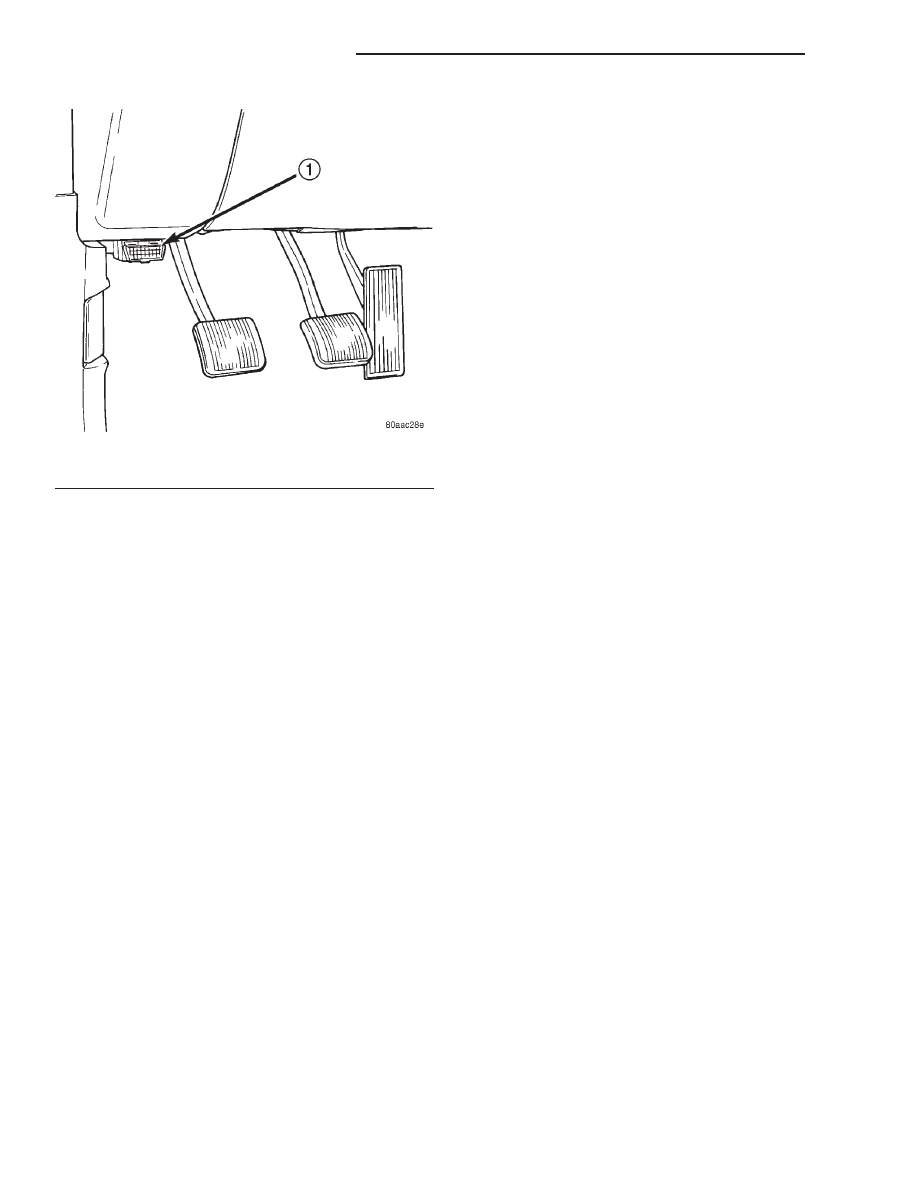
Technicians must retrieve stored DTC’s by connect-
ing the DRB III scan tool (or an equivalent scan tool)
to the 16–way data link connector. This connector is
located on the lower edge of the instrument panel
near the steering column.
OBTAINING DTC’s
WARNING: APPLY
PARKING
BRAKE
AND/OR
BLOCK WHEELS BEFORE PERFORMING ANY TEST
ON AN OPERATING ENGINE.
Fig. 1 Data Link (Diagnostic) Connector Location
1 – 16–WAY DATA LINK CONNECTOR
25 - 2
EMISSION CONTROL SYSTEMS
XJ
DESCRIPTION AND OPERATION (Continued)
(1) Connect the DRB scan tool to data link (diag-
nostic) connector.
(2) Turn the ignition switch on, access Read Fault
Screen. Record all the DTC’s shown on the DRB scan
tool.
(3) To erase DTC’s, use the Erase Trouble Code
data screen on the DRB scan tool.
NOTE: For a list of DTC’s, refer to the following
charts.
DIAGNOSTIC TROUBLE CODE DESCRIPTIONS
(M)
Malfunction Indicator Lamp (MIL) illuminated during engine operation if this DTC was
recorded (depending if required by CARB and/or EPA). MIL is displayed as an engine icon on
instrument panel.
(G)
Generator lamp illuminated
Generic Scan
Tool P-Code
DRB Scan Tool Display
Brief Description of DTC
P0030 (M)
1/1 O2 Sensor Heater Relay Circuit
Problem detected in oxygen sensor heater relay circuit.
P0036 (M)
1/2 O2 Sensor Heater Relay Circuit
Problem detected in oxygen sensor heater relay circuit.
P0106
Barometric Pressure Out of Range
MAP sensor input voltage out of an acceptable range
detected during reading of barometric pressure at key-on.
P0107 (M)
Map Sensor Voltage Too Low
MAP sensor input below minimum acceptable voltage.
P0108 (M)
Map Sensor Voltage Too High
MAP sensor input above maximum acceptable voltage.
P0112 (M)
Intake Air Temp Sensor Voltage Low
Intake air (charge) temperature sensor input below the
minimum acceptable voltage.
P0113 (M)
Intake Air Temp Sensor Voltage High
Intake air (charge) temperature sensor input above the
maximum acceptable voltage.
P0116
A rationatilty error has been detected in the coolant temp
sensor.
P0117 (M)
ECT Sensor Voltage Too Low
Engine coolant temperature sensor input below the
minimum acceptable voltage.
P0118 (M)
ECT Sensor Voltage Too High
Engine coolant temperature sensor input above the
maximum acceptable voltage.
P0121 (M)
TPS Voltage Does Not Agree With
MAP
TPS signal does not correlate to MAP sensor signal.
P0121 (M)
Accelerator Position Sensor (APPS)
Signal Voltage Too Low
APPS voltage input below the minimum acceptable
voltage.
P0122 (M)
Throttle Position Sensor Voltage Low
Throttle position sensor input below the acceptable
voltage range.
P0122 (M)
Accelerator Position Sensor (APPS)
Signal Voltage Too Low
APPS voltage input below the minimum acceptable
voltage.
P0123 (M)
Throttle Position Sensor Voltage
High
Throttle position sensor input above the maximum
acceptable voltage.
P0123 (M)
Accelerator Position Sensor (APPS)
Signal Voltage Too High
APPS voltage input above the maximum acceptable
voltage.
P0125 (M)
Closed Loop Temp Not Reached
Time to enter Closed Loop Operation (Fuel Control) is
excessive.
P0125 (M)
Engine is Cold Too Long
Engine does not reach operating temperature.
P0130 (M)
1/1 O2 Sensor Heater Circuit
Malfunction
Oxygen sensor heater element malfunction.
XJ
EMISSION CONTROL SYSTEMS
25 - 3
DESCRIPTION AND OPERATION (Continued)

(M)
Malfunction Indicator Lamp (MIL) illuminated during engine operation if this DTC was
recorded (depending if required by CARB and/or EPA). MIL is displayed as an engine icon on
instrument panel.
P0131 (M)
1/1 O2 Sensor Shorted To Ground
Oxygen sensor input voltage maintained below normal
operating range.
P0132 (M)
1/1 O2 Sensor Shorted To Voltage
Oxygen sensor input voltage maintained above normal
operating range.
P0133 (M)
1/1 O2 Sensor Slow Response
Oxygen sensor response slower than minimum required
switching frequency.
P0134 (M)
1/1 O2 Sensor Stays at Center
Neither rich or lean condition is detected from the oxygen
sensor input.
P0135 (M)
1/1 O2 Sensor Heater Failure
Oxygen sensor heater element malfunction.
P0136 (M)
1/2 O2 Sensor Heater Circuit
Malfunction
Oxygen sensor heater element malfunction.
P0137 (M)
1/2 O2 Sensor Shorted To Ground
Oxygen sensor input voltage maintained below normal
operating range.
P0138 (M)
1/2 O2 Sensor Shorted To Voltage
Oxygen sensor input voltage maintained above normal
operating range.
P0139 (M)
1/2 O2 Sensor Slow Response
Oxygen sensor response not as expected.
P0140 (M)
1/2 O2 Sensor Stays at Center
Neither rich or lean condition is detected from the oxygen
sensor.
P0141 (M)
1/2 O2 Sensor Heater Failure
Oxygen sensor heater element malfunction.
P0143 (M)
1/3 O2 Sensor Shorted To Ground
Oxygen sensor input voltage maintained below normal
operating range.
P0144 (M)
1/3 O2 Sensor Shorted To Voltage
Oxygen sensor input voltage maintained above normal
operating range.
P0145 (M)
1/3 O2 Sensor Slow Response
Oxygen sensor response slower than minimum required
switching frequency.
P0146 (M)
1/3 O2 Sensor Stays at Center
Neither rich or lean condition is detected from the oxygen
sensor.
P0147 (M)
1/3 O2 Sensor Heater Failure
Oxygen sensor heater element malfunction.
P0151 (M)
2/1 O2 Sensor Shorted To Ground
Oxygen sensor input voltage maintained below normal
operating range.
P0152 (M)
2/1 O2 Sensor Shorted To Voltage
Oxygen sensor input voltage sustained above normal
operating range.
P0153 (M)
2/1 O2 Sensor Slow Response
Oxygen sensor response slower than minimum required
switching frequency.
P0154 (M)
2/1 O2 Sensor Stays at Center
Neither rich or lean condition is detected from the oxygen
sensor.
P0155 (M)
2/1 O2 Sensor Heater Failure
Oxygen sensor heater element malfunction.
P0157 (M)
2/2 O2 Sensor Shorted To Ground
Oxygen sensor input voltage maintained below normal
operating range.
P0158 (M)
2/2 O2 Sensor Shorted To Voltage
Oxygen sensor input voltage maintained above normal
operating range.
P0159
2/2 O2 Sensor Slow Response
Oxygen sensor response slower than minimum required
switching frequency.
P0160 (M)
2/2 O2 Sensor Stays at Center
Neither rich or lean condition is detected from the oxygen
sensor.
25 - 4
EMISSION CONTROL SYSTEMS
XJ
DESCRIPTION AND OPERATION (Continued)

(M)
Malfunction Indicator Lamp (MIL) illuminated during engine operation if this DTC was
recorded (depending if required by CARB and/or EPA). MIL is displayed as an engine icon on
instrument panel.
P0161 (M)
2/2 O2 Sensor Heater Failure
Oxygen sensor heater element malfunction.
P0168
Decreased Engine Performance Due
To High Injection Pump Fuel Temp
Fuel temperature is above the engine protection limit.
Engine power will be derated.
P0171 (M)
1/1 Fuel System Lean
A lean air/fuel mixture has been indicated by an
abnormally rich correction factor.
P0172 (M)
1/1 Fuel System Rich
A rich air/fuel mixture has been indicated by an
abnormally lean correction factor.
P0174 (M)
2/1 Fuel System Lean
A lean air/fuel mixture has been indicated by an
abnormally rich correction factor.
P0175 (M)
2/1 Fuel System Rich
A rich air/fuel mixture has been indicated by an
abnormally lean correction factor.
P0176
Loss of Flex Fuel Calibration Signal
No calibration voltage present from flex fuel sensor.
P0177
Water In Fuel
Excess water found in fuel by water-in-fuel sensor.
P0178
Flex Fuel Sensor Volts Too Low
Flex fuel sensor input below minimum acceptable voltage.
P0178
Water In Fuel Sensor Voltage Too
Low
Loss of water-in-fuel circuit or sensor.
P0179
Flex Fuel Sensor Volts Too High
Flex fuel sensor input above maximum acceptable
voltage.
P0181
Fuel Injection Pump Failure
Low power, engine derated, or engine stops.
P0182 (M)
CNG Temp Sensor Voltage Too Low
Compressed natural gas temperature sensor voltage
below acceptable voltage.
P0183 (M)
CNG Temp Sensor Voltage Too High
Compressed natural gas temperature sensor voltage
above acceptable voltage.
P0201 (M)
Injector #1 Control Circuit
An open or shorted condition detected in control circuit for
injector #1 or the INJ 1 injector bank.
P0202 (M)
Injector #2 Control Circuit
An open or shorted condition detected in control circuit for
injector #2 or the INJ 2 injector bank.
P0203 (M)
Injector #3 Control Circuit
An open or shorted condition detected in control circuit for
injector #3 or the INJ 3 injector bank.
P0204 (M)
Injector #4 Control Circuit
Injector #4 or INJ 4 injector bank output driver stage does
not respond properly to the control signal.
P0205 (M)
Injector #5 Control Circuit
Injector #5 output driver stage does not respond properly
to the control signal.
P0206 (M)
Injector #6 Control Circuit
Injector #6 output driver stage does not respond properly
to the control signal.
P0207 (M)
Injector #7 Control Circuit
Injector #7 output driver stage does not respond properly
to the control signal.
P0208 (M)
Injector #8 Control Circuit
Injector #8 output driver stage does not respond properly
to the control signal.
P0209 (M)
Injector #9 Control Circuit
Injector #9 output driver stage does not respond properly
to the control signal.
P0210 (M)
Injector #10 Control Circuit
Injector #10 output driver stage does not respond properly
to the control signal.
P0215
Fuel Injection Pump Control Circuit
Failure in fuel pump relay control circuit.
XJ
EMISSION CONTROL SYSTEMS
25 - 5
DESCRIPTION AND OPERATION (Continued)

(M)
Malfunction Indicator Lamp (MIL) illuminated during engine operation if this DTC was
recorded (depending if required by CARB and/or EPA). MIL is displayed as an engine icon on
instrument panel.
P0216 (M)
Fuel Injection Pump Timing Failure
High fuel supply restriction, low fuel pressure or possible
wrong or incorrectly installed pump keyway.
P0217
Decreased Engine Performance Due
To Engine Overheat Condition
Engine overheating. ECM will derate engine performance.
P0219
Crankshaft Position Sensor
Overspeed Signal
Engine has exceeded rpm limits.
P0222 (M)
Idle Validation Signals Both Low
Problem detected with idle validation circuits within APPS.
P0223 (M)
Idle Validation Signals Both High
(Above 5 Volts)
Problem detected with idle validation circuits within APPS.
P0230
Transfer Pump (Lift Pump) Circuit
Out of Range
Problem detected in fuel transfer pump circuits.
P0232
Fuel Shutoff Signal Voltage Too High
Fuel shut-off signal voltage too high from ECM to fuel
injection pump.
P0234 (M)
Turbo Boost Limit Exceeded
Problem detected in turbocharger wastegate.
P0236 (M)
Map Sensor Too High Too Long
Problem detected in turbocharger wastegate.
P0237 (M)
Map Sensor Voltage Too Low
MAP sensor voltage input below the minimum acceptable
voltage.
P0238 (M)
Map Sensor Voltage Too High
MAP sensor voltage input above the maximum
acceptable voltage.
P0251 (M)
Fuel Inj. Pump Mech. Failure Fuel
Valve Feedback Circuit
Problem sensed with fuel circuit internal to fuel injection
pump.
P0253 (M)
Fuel Injection Pump Fuel Valve
Open Circuit
Problem sensed with fuel circuit internal to fuel injection
pump.
P0254
Fuel Injection Pump Fuel Valve
Current Too High
Problem caused by internal fuel injection pump failure.
P0300 (M)
Multiple Cylinder Mis-fire
Misfire detected in multiple cylinders.
P0301 (M)
CYLINDER #1 MISFIRE
Misfire detected in cylinder #1.
P0302 (M)
CYLINDER #2 MISFIRE
Misfire detected in cylinder #2.
P0303 (M)
CYLINDER #3 MISFIRE
Misfire detected in cylinder #3.
P0304 (M)
CYLINDER #4 MISFIRE
Misfire detected in cylinder #4.
P0305 (M)
CYLINDER #5 MISFIRE
Misfire detected in cylinder #5.
P0306 (M)
CYLINDER #6 MISFIRE
Misfire detected in cylinder #6.
P0307 (M)
CYLINDER #7 MISFIRE
Misfire detected in cylinder #7
P0308 (M)
CYLINDER #8 MISFIRE
Misfire detected in cylinder #8.
P0309 (M)
CYLINDER #9 MISFIRE
Misfire detected in cylinder #9.
P0310 (M)
CYLINDER #10 MISFIRE
Misfire detected in cylinder #10.
P0320 (M)
No Crank Referance Signal at PCM
No reference signal (crankshaft position sensor) detected
during engine cranking.
P0320 (M)
No RPM Signal to PCM (Crankshaft
Position Sensor Signal to JTEC)
A CKP signal has not been detected at the PCM.
P0325
Knock Sensor #1 Circuit
Knock sensor (#1) signal above or below minimum
acceptable threshold voltage at particular engine speeds.
25 - 6
EMISSION CONTROL SYSTEMS
XJ
DESCRIPTION AND OPERATION (Continued)

(M)
Malfunction Indicator Lamp (MIL) illuminated during engine operation if this DTC was
recorded (depending if required by CARB and/or EPA). MIL is displayed as an engine icon on
instrument panel.
P0330
Knock Sensor #2 Circuit
Knock sensor (#2) signal above or below minimum
acceptable threshold voltage at particular engine speeds.
P0336 (M)
Crankshaft Position (CKP) Sensor
Signal
Problem with voltage signal from CKP.
P0340 (M)
No Cam Signal At PCM
No fuel sync
P0341 (M)
Camshaft Position (CMP) Sensor
Signal
Problem with voltage signal from CMP.
P0350
Ignition Coil Draws Too Much
Current
A coil (1-5) is drawing too much current.
P0351 (M)
Ignition Coil # 1 Primary Circuit
Peak primary circuit current not achieved with maximum
dwell time.
P0352 (M)
Ignition Coil # 2 Primary Circuit
Peak primary circuit current not achieved with maximum
dwell time.
P0353 (M)
Ignition Coil # 3 Primary Circuit
Peak primary circuit current not achieved with maximum
dwell time.
P0354 (M)
Ignition Coil # 4 Primary Circuit
Peak primary circuit current not achieved with maximum
dwell time (High Impedance).
P0355 (M)
Ignition Coil # 5 Primary Circuit
Peak primary circuit current not achieved with maximum
dwell time (High Impedance).
P0356 (M)
Ignition Coil # 6 Primary Circuit
Peak primary circuit current not achieved with maximum
dwell time (high impedance).
P0357 (M)
Ignition Coil # 7 Primary Circuit
Peak primary circuit current not achieved with maximum
dwell time (high impedance).
P0358 (M)
Ignition Coil # 8 Primary Circuit
Peak primary circuit current not achieved with maximum
dwell time (high impedance).
P0370
Fuel Injection Pump Speed/Position
Sensor Sig Lost
Problem caused by internal fuel injection pump failure.
P0380 (M)
Intake Air Heater Relay #1 Control
Circuit
Problem detected in #1 air heater solenoid/relay circuit
(not heater element)
P0381 (M)
Wait To Start Lamp Inoperative
Problem detected in wait-to-start bulb circuit.
P0382 (M)
Intake Air Heater Relay #2 Control
Circuit
Problem detected in #2 air heater solenoid/relay circuit
(not heater element)
P0387
Crankshaft Position Sensor Supply
Voltage Too Low
CKP sensor voltage input below the minimum acceptable
voltage.
P0388
Crankshaft Position Sensor Supply
Voltage Too High
CKP sensor voltage input above the maximum acceptable
voltage.
P0401
EGR System Failure
Required change in air/fuel ration not detected during
diagnostic test.
P0403
EGR Solenoid Circuit
An open or shorted condition detected in the EGR
solenoid control circuit.
P0404
EGR Position Sensor Rationality
EGR position sensor signal does not correlate to EGR
duty cycle.
P0405
EGR Position Sensor Volts Too Low
EGR position sensor input below the acceptable voltage
range.
XJ
EMISSION CONTROL SYSTEMS
25 - 7
DESCRIPTION AND OPERATION (Continued)

(M)
Malfunction Indicator Lamp (MIL) illuminated during engine operation if this DTC was
recorded (depending if required by CARB and/or EPA). MIL is displayed as an engine icon on
instrument panel.
P0406
EGR Position Sensor Volts Too High
EGR position sensor input above the acceptable voltage
range.
P0412
Secondary Air Solenoid Circuit
An open or shorted condition detected in the secondary
air (air switching/aspirator) solenoid control circuit.
P0420 (M)
1/1 Catalytic Converter Efficiency
Catalyst 1/1 efficiency below required level.
P0432 (M)
1/2 Catalytic Converter Efficiency
Catalyst 2/1 efficiency below required level.
P0441 (M)
Evap Purge Flow Monitor
Insufficient or excessive vapor flow detected during
evaporative emission system operation.
P0442 (M)
Evap Leak Monitor Medium Leak
Detected
A small leak has been detected in the evaporative
system.
P0443 (M)
Evap Purge Solenoid Circuit
An open or shorted condition detected in the EVAP purge
solenoid control circuit.
P0455 (M)
Evap Leak Monitor Large Leak
Detected
A large leak has been detected in the evaporative system.
P0456 (M)
Evap Leak Monitor Small Leak
Detected
Leak has been detected in the evaporative system.
P0460
Fuel Level Unit No Change Over
Miles
During low fuel
P0460
Fuel Level Unit No Change Over
Miles
Fuel level sending unit voltage does not change for more
than 40 miles.
P0462
Fuel Level Sending Unit Volts Too
Low
Fuel level sensor input below acceptable voltage.
P0462 (M)
Fuel Level Sending Unit Volts Too
Low
Open circuit between PCM and fuel gauge sending unit.
P0463
Fuel Level Sending Unit Volts Too
High
Fuel level sensor input above acceptable voltage.
P0463 (M)
Fuel Level Sending Unit Volts Too
High
Circuit shorted to voltage between PCM and fuel gauge
sending unit.
P0500 (M)
No Vehicle Speed Sensor Signal
No vehicle speed sensor signal detected during road load
conditions.
P0500 (M)
No Vehicle Speed Sensor Signal
A vehicle speed signal was not detected.
P0505 (M)
Idle Air Control Motor Circuits
SBEC II
P0522
Oil Pressure Voltage Too Low
Oil pressure sending unit (sensor) voltage input below the
minimum acceptable voltage.
P0523
Oil Pressure Voltage Too High
Oil pressure sending unit (sensor) voltage input above the
maximum acceptable voltage.
P0524
Oil Pressure Too Low
Engine oil pressure is low. Engine power derated.
P0545
A/C Clutch Relay Circuit
Problem detected in air conditioning clutch relay control
circuit.
P0551
Power Steering Switch Failure
Incorrect input state detected for the power steering
switch circuit. PL: High pressure seen at high speed.
P0562
Charging System Voltage Too Low
Supply voltage sensed at ECM too low.
P0563
Charging System Voltage Too High
Supply voltage sensed at ECM too high.
25 - 8
EMISSION CONTROL SYSTEMS
XJ
DESCRIPTION AND OPERATION (Continued)

(M)
Malfunction Indicator Lamp (MIL) illuminated during engine operation if this DTC was
recorded (depending if required by CARB and/or EPA). MIL is displayed as an engine icon on
instrument panel.
P0600
PCM Failure SPI Communications
No communication detected between co-processors in the
control module.
P0601 (M)
Internal Controller Failure
Internal control module fault condition (check sum)
detected.
P0602 (M)
ECM Fueling Calibration Error
ECM Internal fault condition detected.
P0604
RAM Check Failure
Transmission control module RAM self test fault detected.
-Aisin transmission
P0605
ROM Check Falure
Transmission control module ROM self test fault detected
-Aisin transmission
P0606 (M)
ECM Failure
ECM Internal fault condition detected.
P0615
Starter Relay Control Circuit
An open or shorted condition detected in the starter relay
control circuit.
P0622 (G)
Generator Field Not Switching
Properly
An open or shorted condition detected in the generator
field control circuit.
P0645
A/C Clutch Relay Circuit
An open or shorted condition detected in the A/C clutch
relay control circuit.
P0700
EATX Controller DTC Present
This SBEC III or JTEC DTC indicates that the EATX or
Aisin controller has an active fault and has illuminated the
MIL via a CCD (EATX) or SCI (Aisin) message. The
specific fault must be acquired from the EATX via CCD or
from the Aisin via ISO-9141.
P0703
Brake Switch Stuck Pressed or
Released
Incorrect input state detected in the brake switch circuit.
(Changed from P1595)
P0711 (M)
Trans Temp Sensor, No Temp Rise
After Start
Relationship between the transmission temperature and
overdrive operation and/or TCC operation indicates a
failure of the Transmission Temperature Sensor. OBD II
Rationality. Was MIL code 37.
P0712
Trans Temp Sensor Voltage Too Low
Transmission fluid temperature sensor input below
acceptable voltage. Was MIL code 37.
P0712 (M)
Trans Temp Sensor Voltage Too Low
Voltage less than 1.55 volts (4-speed auto. trans. only).
P0713
Trans Temp Sensor Voltage Too
High
Transmission fluid temperature sensor input above
acceptable voltage. Was MIL code 37.
P0713 (M)
Trans Temp Sensor Voltage Too
High
Voltage greater than 3.76 volts (4-speed auto. trans.
only).
P0720 (M)
Low Output SPD Sensor RPM,
Above 15 MPH
The relationship between the Output Shaft Speed Sensor
and vehicle speed is not within acceptable limits.
P0720 (M)
Low Output Spd Sensor RPM Above
15 mph
Output shaft speed is less than 60 rpm with vehicle speed
above 15 mph (4-speed auto. trans. only).
P0740 (M)
Torq Con Clu, No RPM Drop at
Lockup
Relationship between engine and vehicle speeds
indicated failure of torque convertor clutch lock-up system
(TCC/PTU solenoid)
P0743 (M)
Torque Converter Clutch Solenoid/
Trans Relay Circuits
An open or shorted condition detected in the torque
converter clutch (part throttle unlock) solenoid control
circuit. Shift solenoid C electrical fault - Aisin transmission
XJ
EMISSION CONTROL SYSTEMS
25 - 9
DESCRIPTION AND OPERATION (Continued)

(M)
Malfunction Indicator Lamp (MIL) illuminated during engine operation if this DTC was
recorded (depending if required by CARB and/or EPA). MIL is displayed as an engine icon on
instrument panel.
P0743 (M)
Torque Converter Clutch Solenoid/
Trans Relay Circuits
An open or shorted condition detected in the torque
converter part throttle unlock solenoid control circuit (3 or
4-speed auto. trans. only).
P0748 (M)
Governor Pressur Sol Control/Trans
Relay Circuits
An open or shorted condition detected in the Governor
Pressure Solenoid circuit or Trans Relay Circuit in JTEC
RE transmissions.
P0748 (M)
Governor Pressure Sol Control/Trans
Relay Circuits
An open or shorted condition detected in the governor
pressure solenoid or relay circuits (4-speed auto. trans.
only).
P0751 (M)
O/D Switch Pressed (Lo) More Than
5 Minutes
Overdrive override switch input is in a prolonged
depressed state.
P0751 (M)
O/D Switch Pressed (LO) More Than
5 Min
Overdrive Off switch input too low for more than 5
minutes (4-speed auto. trans. only).
P0753 (M)
Trans 3-4 Shift Sol/Trans Relay
Circuits
An open or shorted condition detected in the overdrive
solenoid control circuit or Trans Relay Circuit in JTEC RE
transmissions. Was MIL code 45.
P0753 (M)
Trans 3-4 Shift Sol/Trans Relay
Circuits
An open or shorted condition detected in the transmission
2-4 shift solenoid circuit (4-speed auto. trans. only).
P0756
AW4 Shift Sol B (2-3) Functional
Failure
Shift solenoid B (2-3) functional fault - Aisin transmission
P0783 (M)
3-4 Shift Sol, No RPM Drop at
Lockup
The overdrive solenoid is unable to engage the gear
change from 3rd gear to the overdrive gear.
P0801
Reverse Gear Lockout Circuit Open
or Short
An open or shorted condition detected in the transmission
reverse gear lock-out solenoid control circuit.
P0830
Clutch Depressed Switch Circuit
Problem detected in clutch switch circuit.
P0833
Clutch Released Switch Circuit
Problem detected in clutch switch circuit.
P1110
Decrease Engine Performance Due
To High Intake Air Temperature
Intake manifold air temperature is above the engine
protection limit. Engine power will be derated.
P1180
Decreased Engine Performance Due
To High Injection Pump Fuel Temp
Fuel temperature is above the engine protection limit.
Engine power will be derated.
P1195 (M)
1/1 O2 Sensor Slow During Catalyst
Monitor
A slow switching oxygen sensor has been detected in
bank 1/1 during catalyst monitor test. (Also see SCI DTC
$66) (was P0133)
P1196 (M)
2/1 O2 Sensor Slow During Catalyst
Monitor
A slow switching oxygen sensor has been detected in
bank 2/1 during catalyst monitor test. (Also see SCI DTC
$7A) (was P0153)
P1197
1/2 O2 Sensor Slow During Catalyst
Monitor
A slow switching oxygen sensor has been detected in
bank 1/2 during catalyst monitor test. (Also see SCI DTC
$68) (was P0139)
P1198
Radiator Temperature Sensor Volts
Too High
Radiator coolant temperature sensor input above the
maximum acceptable voltage.
P1199
Radiator Temperature Sensor Volts
Too Low
Radiator coolant temperature sensor input below the
minimum acceptable voltage.
P1281
Engine is Cold Too Long
Engine coolant temperature remains below normal
operating temperatures during vehicle travel (Thermostat).
25 - 10
EMISSION CONTROL SYSTEMS
XJ
DESCRIPTION AND OPERATION (Continued)

(M)
Malfunction Indicator Lamp (MIL) illuminated during engine operation if this DTC was
recorded (depending if required by CARB and/or EPA). MIL is displayed as an engine icon on
instrument panel.
P1282
Fuel Pump Relay Control Circuit
An open or shorted condition detected in the fuel pump
relay control circuit.
P1283
Idle Select Signal Invalid
ECM or fuel injection pump module internal fault condition
detected.
P1284 (M)
Fuel Injection Pump Battery Voltage
Out-Of-Range
Fuel injection pump module internal fault condition
detected. Engine power will be derated.
P1285 (M)
Fuel Injection Pump Controller
Always On
Fuel injection pump module relay circuit failure detected.
Engine power will be derated.
P1286
Accelerator Position Sensor (APPS)
Supply Voltage Too High
High voltage detected at APPS.
P1287
Fuel Injection Pump Controller
Supply Voltage Low
ECM or fuel injection pump module internal fault condition
detected. Engine power will be derated.
P1288
Intake Manifold Short Runner
Solenoid Circuit
An open or shorted condition detected in the short runner
tuning valve circuit.
P1289
Manifold Tune Valve Solenoid Circuit
An open or shorted condition detected in the manifold
tuning valve solenoid control circuit.
P1290
CNG Fuel System Pressure Too
High
Compressed natural gas system pressure above normal
operating range.
P1291
No Temp Rise Seen From Intake
Heaters
Energizing Heated Air Intake does not change intake air
temperature sensor an acceptable amount.
P1291 (M)
No Temperature Rise Seen From
Intake Air Heaters
Problem detected in intake manifold air heating system.
P1292
CNG Pressure Sensor Voltage Too
High
Compressed natural gas pressure sensor reading above
acceptable voltage.
P1293
CNG Pressure Sensor Voltage Too
Low
Compressed natural gas pressure sensor reading below
acceptable voltage.
P1294 (M)
Target Idle Not Reached
Target RPM not achieved during drive idle condition.
Possible vacuum leak or IAC (AIS) lost steps.
P1295 (M)
No 5 Volts to TP Sensor
Loss of a 5 volt feed to the Throttle Position Sensor has
been detected.
P1295 (M)
Accelerator Position Sensor (APPS)
Supply Voltage Too Low
APPS supply voltage input below the minimum
acceptable voltage.
P1296
No 5 Volts to MAP Sensor
Loss of a 5 volt feed to the MAP Sensor has been
detected.
P1297 (M)
No Change in MAP From Start To
Run
No difference is recognized between the MAP reading at
engine idle and the stored barometric pressure reading.
P1298
Lean Operation at Wide Open
Throttle
A prolonged lean condition is detected during Wide Open
Throttle
P1299
Vacuum Leak Found (IAC Fully
Seated)
MAP Sensor signal does not correlate to Throttle Position
Sensor signal. Possible vacuum leak.
P1388
Auto Shutdown Relay Control Circuit
An open or shorted condition detected in the ASD or CNG
shutoff relay control ckt.
P1388
Auto Shutdown Relay Control Circuit
An open or shorted condition detected in the auto
shutdown relay circuit.
XJ
EMISSION CONTROL SYSTEMS
25 - 11
DESCRIPTION AND OPERATION (Continued)

(M)
Malfunction Indicator Lamp (MIL) illuminated during engine operation if this DTC was
recorded (depending if required by CARB and/or EPA). MIL is displayed as an engine icon on
instrument panel.
P1389
No ASD Relay Output Voltage At
PCM
No Z1 or Z2 voltage sensed when the auto shutdown
relay is energized.
P1389 (M)
No ASD Relay Output Voltage at
PCM
An open condition detected In the ASD relay output
circuit.
P1390
Timing Belt Skipped 1 Tooth or More
Relationship between Cam and Crank signals not correct
P1391 (M)
Intermittent Loss of CMP or CKP
Loss of the Cam Position Sensor or Crank Position
sensor has occurred. For PL 2.0L
P1398 (M)
Mis-Fire Adaptive Numerator at Limit
PCM is unable to learn the Crank Sensor’s signal in
preparation for Misfire Diagnostics. Probable defective
Crank Sensor
P1399
Wait To Start Lamp Cicuit
An open or shorted condition detected in the Wait to Start
Lamp circuit.
P1403
No 5V to EGR Sens
Loss of 5v feed to the EGR position sensor.
P01475
Aux 5 Volt Supply Voltage High
Sensor supply voltage for ECM sensors is too high.
P1476
Too Little Secondary Air
Insufficient flow of secondary air injection detected during
aspirator test (was P0411)
P1477
Too Much Secondary Air
Excessive flow of secondary air injection detected during
aspirator test (was P0411).
P1478
Battery Temp Sensor Volts Out of
Limit
Internal temperature sensor input voltage out of an
acceptable range.
P1479
Transmission Fan Relay Circuit
An open or shorted condition detected in the transmission
fan relay circuit.
P1480
PCV Solenoid Circuit
An open or shorted condition detected in the PCV
solenoid circuit.
P1481
EATX RPM Pulse Perf
EATX RPM pulse generator signal for misfire detection
does not correlate with expected value.
P1482
Catalyst Temperature Sensor Circuit
Shorted Low
Catalyst temperature sensor circuit shorted low.
P1483
Catalyst Temperature Sensor Circuit
Shorted High.
Catalyst temperature sensor circuit shorted high.
P1484
Catalytic Converter Overheat
Detected
A catalyst overheat condition has been detected by the
catalyst temperature sensor.
P1485
Air Injection Solenoid Circuit
An open or shorted condition detected in the air assist
solenoid circuit.
P1486
Evap Leak Monitor Pinched Hose
Found
LDP has detected a pinched hose in the evaporative hose
system.
P1487
Hi Speed Rad Fan CTRL Relay
Circuit
An open or shorted condition detected in the control
circuit of the #2 high speed radiator fan control relay.
P1488
Auxiliary 5 Volt Supply Output Too
Low
Auxiliary 5 volt sensor feed is sensed to be below an
acceptable limit.
P1488
5 Volt Supply Voltage Low
Sensor supply voltage for ECM sensors is too low.
P1489
High Speed Fan CTRL Relay Circuit
An open or shorted condition detected in the control
circuit of the high speed radiator fan control relay.
P1490
Low Speed Fan CTRL Relay Circuit
An open or shorted condition detected in control circuit of
the low speed radiator fan control relay.
25 - 12
EMISSION CONTROL SYSTEMS
XJ
DESCRIPTION AND OPERATION (Continued)

(M)
Malfunction Indicator Lamp (MIL) illuminated during engine operation if this DTC was
recorded (depending if required by CARB and/or EPA). MIL is displayed as an engine icon on
instrument panel.
P1491
Rad Fan Control Relay Circuit
An open or shorted condition detected in the radiator fan
control relay control circuit. This includes PWM solid state
relays.
P1492
Ambient/Batt Temp Sen Volts Too
High
External temperature sensor input above acceptable
voltage.
P1492 (M)
Ambient/Batt Temp Sensor Volts Too
High
Battery temperature sensor input voltage above an
acceptable range.
P1493 (M)
Ambient/Batt Temp Sen Volts Too
Low
External temperature sensor input below acceptable
voltage.
P1493 (M)
Ambient/Batt Temp Sen Volts Too
Low
Battery temperature sensor input voltage below an
acceptable range.
P1494 (M)
Leak Detection Pump Sw or
Mechanical Fault
Incorrect input state detected for the Leak Detection
Pump (LDP) pressure switch.
P1495
Leak Detection Pump Solenoid
Circuit
An open or shorted condition detected in the Leak
Detection Pump (LDP) solenoid circuit.
P1496
5 Volt Supply, Output Too Low
5 volt sensor feed is sensed to be below an acceptable
limit. ( less than 4v for 4 sec )
P1498
High Speed Rad Fan Ground CTRL
Rly Circuit
An open or shorted condition detected in the control
circuit of the #3 high speed radiator fan control relay.
P1594 (G)
Charging System Voltage Too High
Battery voltage sense input above target charging voltage
during engine operation.
P1594
Charging System Voltage Too High
Battery voltage sense input above target charging voltage
during engine operation.
P1595
Speed Control Solenoid Circuits
An open or shorted condition detected in either of the
speed control vacuum or vent solenoid control circuits.
P1595
Speed Control Solenoid Circuits
An open or shorted condition detected in the speed
control vacuum or vent solenoid circuits.
P1596
Speed Control Switch Always High
Speed control switch input above maximum acceptable
voltage.
P1597
Speed Control Switch Always Low
Speed control switch input below minimum acceptable
voltage.
P1597
Speed Control Switch Always Low
Speed control switch input below the minimum acceptable
voltage.
P1598
A/C Pressure Sensor Volts Too High
A/C pressure sensor input above maximum acceptable
voltage.
P1598
A/C Sensor Input Hi
Problem detected in air conditioning electrical circuit.
P1599
A/C Pressure Sensor Volts Too Low
A/C pressure sensor input below minimum acceptable
voltage.
P1599
A/C Sensor Input Lo
Problem detected in air conditioning electrical circuit.
P1680
Clutch Released Switch Circuit
Problem detected in clutch switch electrical circuit.
P1681
No I/P Cluster CCD/J1850
Messages Received
No CCD/J1850 messages received from the cluster
control module.
XJ
EMISSION CONTROL SYSTEMS
25 - 13
DESCRIPTION AND OPERATION (Continued)

(M)
Malfunction Indicator Lamp (MIL) illuminated during engine operation if this DTC was
recorded (depending if required by CARB and/or EPA). MIL is displayed as an engine icon on
instrument panel.
P1682 (G)
Charging System Voltage Too Low
Battery voltage sense input below target charging voltage
during engine operation and no significant change in
voltage detected during active test of generator output
circuit.
P1682
Charging System Voltage Too Low
Charging system output voltage low.
P1683
SPD CTRL PWR Relay; or S/C 12v
Driver CKT
An open or shorted condition detected in the speed
control servo power control circuit.
P1683
Spd ctrl pwr rly, or s/c 12v driver
circuit
An open or shorted condition detected in the speed
control servo power control circuit.
P1684
Batt Loss in 50 Star
The battery has been disconnected within the last 50
starts
P1685
SKIM Invalid Key
The engine controler has received an invalid key from the
SKIM.
P1686
No SKIM BUS Messages Received
No CCD/J1850 messages received from the Smart Key
Immobilizer Module (SKIM).
P1687
No MIC BUS Message
No CCD/J1850 messages received from the Mechanical
Instrument Cluster (MIC) module.
P1688 (M)
Internal Fuel Injection Pump
Controller Failure
Internal problem within the fuel injection pump. Low
power, engine derated, or engine stops.
P1689 (M)
No Communication Between ECM
and Injection Pump Module
Data link circuit failure between ECM and fuel injection
pump. Low power, engine derated, or engine stops.
P1690 (M)
Fuel Injection Pump CKP Sensor
Does Not Agree With ECM CKP
Sensor
Problem in fuel sync signal. Possible injection pump
timing problem. Low power, engine derated, or engine
stops.
P1691
Fuel Injection Pump Controller
Calibration Error
Internal fuel injection pump failure. Low power, engine
derated, or engine stops.
P1692
DTC Set In ECM
A “Companion DTC” was set in both the ECM and PCM.
P1693 (M)
DTC Detected in Companion Module
A fault has been generated in the companion engine
control module.
P1693 (M)
DTC Detected in PCM/ECM or DTC
Detected in ECM
A “Companion DTC” was set in both the ECM and PCM.
P1694
Fault In Companion Module
No CCD/J1850 messages received from the powertrain
control module-Aisin transmission
P1694 (M)
No CCD Messages received from
ECM
Bus communication failure to PCM.
P1695
No CCD/J1850 Message From Body
Control Module
No CCD/J1850 messages received from the body control
module.
P1696
PCM Failure EEPROM Write Denied
Unsuccessful attempt to write to an EEPROM location by
the control module.
P1697
PCM Failure SRI Mile Not Stored
Unsuccessful attempt to update Service Reminder
Indicator (SRI or EMR) mileage in the control module
EEPROM.
P1698
No CCD/J1850 Message From TCM
No CCD/J1850 messages received from the electronic
transmission control module (EATX) or the Aisin
transmission controller.
25 - 14
EMISSION CONTROL SYSTEMS
XJ
DESCRIPTION AND OPERATION (Continued)

(M)
Malfunction Indicator Lamp (MIL) illuminated during engine operation if this DTC was
recorded (depending if required by CARB and/or EPA). MIL is displayed as an engine icon on
instrument panel.
P1698
No CCD Messages received from
PCM
Bus communication failure to PCM. A “Companion DTC”
was set in both the ECM and PCM.
P1719
Skip Shift Solenoid Circuit
An open or shorted condition detected in the transmission
2-3 gear lock-out solenoid control circuit.
P1740
TCC or OD Sol Perf
A rationality error has been detected in either the TCC
solenoid or overdrive solenoid systems.
P1740 (M)
TCC OR O/D Solenoid Performance
Problem detected in transmission convertor clutch and/or
overdrive circuits (diesel engine with 4-speed auto. trans.
only).
P1756 (M)
GOV Press Not Equal to Target @
15-20 PSI
The requested pressure and the actual pressure are not
within a tolerance band for the Governor Control System
which is used to regulate governor pressure to control
shifts for 1st, 2nd, and 3rd gear. (Mid Pressure
Malfunction)
P1756 (M)
Governor Pressure Not Equal to
Target @ 15-20 PSI
Governor sensor input not between 10 and 25 psi when
requested (4-speed auto. trans. only).
P1757
GOV Press Not Equal to Target @
15-20 PSI
The requested pressure and the actual pressure are not
within a tolerance band for the Governor Control System
which is used to regulate governor pressure to control
shifts for 1st, 2nd, and 3rd gear (Zero Pressure
Malfunction)
P1757 (M)
Governor Pressure Above 3 PSI In
Gear With 0 MPH
Governor pressure greater than 3 psi when requested to
be 0 psi (4-speed auto. trans. only).
P1762 (M)
Gov Press Sen Offset Volts Too Lo
or High
The Governor Pressure Sensor input is greater than a
calibration limit or is less than a calibration limit for 3
consecutive park/neutral calibrations.
P1762 (M)
Governor Press Sen Offset Volts Too
Low or High
Sensor input greater or less than calibration for 3
consecutive Neutral/Park occurrences (4-speed auto.
trans. only).
P1763
Governor Pressure Sensor Volts Too
Hi
The Governor Pressure Sensor input is above an
acceptable voltage level.
P1763 (M)
Governor Pressure Sensor Volts Too
HI
Voltage greater than 4.89 volts (4-speed auto. trans.
only).
P1764 (M)
Governor Pressure Sensor Volts Too
Low
The Governor Pressure Sensor input is below an
acceptable voltage level.
P1764 (M)
Governor Pressure Sensor Volts Too
Low
Voltage less than.10 volts (4-speed auto. trans. only).
P1765 (M)
Trans 12 Volt Supply Relay CTRL
Circuit
An open or shorted condition is detected in the
Transmission Relay control circuit. This relay supplies
power to the TCC
P1765 (M)
Trans 12 Volt Supply Relay Ctrl
Circuit
Current state of solenoid output port is different than
expected (4-speed auto. trans. only).
P1899 (M)
P/N Switch Stuck in Park or in Gear
Incorrect input state detected for the Park/Neutral switch.
P1899 (M)
P/N Switch Stuck in Park or in Gear
Incorrect input state detected for the Park/Neutral switch
(3 or 4-speed auto. trans. only).
XJ
EMISSION CONTROL SYSTEMS
25 - 15
DESCRIPTION AND OPERATION (Continued)

TASK MANAGER
DESCRIPTION
The PCM is responsible for efficiently coordinating
the operation of all the emissions-related compo-
nents. The PCM is also responsible for determining if
the diagnostic systems are operating properly. The
software designed to carry out these responsibilities
is call the ’Task Manager’.
OPERATION
The Task Manager determines which tests happen
when and which functions occur when. Many of the
diagnostic steps required by OBD II must be per-
formed under specific operating conditions. The Task
Manager software organizes and prioritizes the diag-
nostic procedures. The job of the Task Manager is to
determine if conditions are appropriate for tests to be
run, monitor the parameters for a trip for each test,
and record the results of the test. Following are the
responsibilities of the Task Manager software:
• Test Sequence
• MIL Illumination
• Diagnostic Trouble Codes (DTCs)
• Trip Indicator
• Freeze Frame Data Storage
• Similar Conditions Window
Test Sequence
In many instances, emissions systems must fail
diagnostic tests more than once before the PCM illu-
minates the MIL. These tests are know as ’two trip
monitors.’ Other tests that turn the MIL lamp on
after a single failure are known as ’one trip moni-
tors.’ A trip is defined as ’start the vehicle and oper-
ate it to meet the criteria necessary to run the given
monitor.’
Many of the diagnostic tests must be performed
under certain operating conditions. However, there
are times when tests cannot be run because another
test is in progress (conflict), another test has failed
(pending) or the Task Manager has set a fault that
may cause a failure of the test (suspend).
• Pending
Under some situations the Task Manager will not
run a monitor if the MIL is illuminated and a fault is
stored from another monitor. In these situations, the
Task Manager postpones monitors pending resolu-
tion of the original fault. The Task Manager does not
run the test until the problem is remedied.
For example, when the MIL is illuminated for an
Oxygen Sensor fault, the Task Manager does not run
the Catalyst Monitor until the Oxygen Sensor fault is
remedied. Since the Catalyst Monitor is based on sig-
nals from the Oxygen Sensor, running the test would
produce inaccurate results.
• Conflict
There are situations when the Task Manager does
not run a test if another monitor is in progress. In
these situations, the effects of another monitor run-
ning could result in an erroneous failure. If this con-
flict is present, the monitor is not run until the
conflicting condition passes. Most likely the monitor
will run later after the conflicting monitor has
passed.
For example, if the Fuel System Monitor is in
progress, the Task Manager does not run the EGR
Monitor. Since both tests monitor changes in air/fuel
ratio and adaptive fuel compensation, the monitors
will conflict with each other.
• Suspend
Occasionally the Task Manager may not allow a two
trip fault to mature. The Task Manager will sus-
pend the maturing of a fault if a condition exists
that may induce an erroneous failure. This prevents
illuminating the MIL for the wrong fault and allows
more precis diagnosis.
For example, if the PCM is storing a one trip fault
for the Oxygen Sensor and the EGR monitor, the
Task Manager may still run the EGR Monitor but
will suspend the results until the Oxygen Sensor
Monitor either passes or fails. At that point the Task
Manager can determine if the EGR system is actu-
ally failing or if an Oxygen Sensor is failing.
MIL Illumination
The PCM Task Manager carries out the illumina-
tion of the MIL. The Task Manager triggers MIL illu-
mination upon test failure, depending on monitor
failure criteria.
The Task Manager Screen shows both a Requested
MIL state and an Actual MIL state. When the MIL is
illuminated upon completion of a test for a third trip,
the Requested MIL state changes to OFF. However,
the MIL remains illuminated until the next key
cycle. (On some vehicles, the MIL will actually turn
OFF during the third key cycle) During the key cycle
for the third good trip, the Requested MIL state is
OFF, while the Actual MILL state is ON. After the
next key cycle, the MIL is not illuminated and both
MIL states read OFF.
Diagnostic Trouble Codes (DTCs)
With OBD II, different DTC faults have different
priorities according to regulations. As a result, the
priorities determine MIL illumination and DTC era-
sure. DTCs are entered according to individual prior-
ity. DTCs with a higher priority overwrite lower
priority DTCs.
Priorities
• Priority 0 —Non-emissions related trouble codes
25 - 16
EMISSION CONTROL SYSTEMS
XJ
DESCRIPTION AND OPERATION (Continued)

• Priority 1 — One trip failure of a two trip fault
for non-fuel system and non-misfire.
• Priority 2 — One trip failure of a two trip fault
for fuel system (rich/lean) or misfire.
• Priority 3 — Two trip failure for a non-fuel sys-
tem and non-misfire or matured one trip comprehen-
sive component fault.
• Priority 4 — Two trip failure or matured fault
for fuel system (rich/lean) and misfire or one trip cat-
alyst damaging misfire.
Non-emissions related failures have no priority.
One trip failures of two trip faults have low priority.
Two trip failures or matured faults have higher pri-
ority. One and two trip failures of fuel system and
misfire monitor take precedence over non-fuel system
and non-misfire failures.
DTC Self Erasure
With one trip components or systems, the MIL is
illuminated upon test failure and DTCs are stored.
Two trip monitors are components requiring failure
in two consecutive trips for MIL illumination. Upon
failure of the first test, the Task Manager enters a
maturing code. If the component fails the test for a
second time the code matures and a DTC is set.
After three good trips the MIL is extinguished and
the Task Manager automatically switches the trip
counter to a warm-up cycle counter. DTCs are auto-
matically erased following 40 warm-up cycles if the
component does not fail again.
For misfire and fuel system monitors, the compo-
nent must pass the test under a Similar Conditions
Window in order to record a good trip. A Similar Con-
ditions Window is when engine RPM is within
6375
RPM and load is within
610% of when the fault
occurred.
NOTE: It is important to understand that a compo-
nent does not have to fail under a similar window of
operation to mature. It must pass the test under a
Similar Conditions Window when it failed to record
a Good Trip for DTC erasure for misfire and fuel
system monitors.
DTCs can be erased anytime with a DRB III. Eras-
ing the DTC with the DRB III erases all OBD II
information. The DRB III automatically displays a
warning that erasing the DTC will also erase all
OBD II monitor data. This includes all counter infor-
mation for warm-up cycles, trips and Freeze Frame.
Trip Indicator
The Trip is essential for running monitors and
extinguishing the MIL. In OBD II terms, a trip is a
set of vehicle operating conditions that must be met
for a specific monitor to run. All trips begin with a
key cycle.
Good Trip
The Good Trip counters are as follows:
• Specific Good Trip
• Fuel System Good Trip
• Misfire Good Trip
• Alternate Good Trip (appears as a Global Good
Trip on DRB III)
• Comprehensive Components
• Major Monitor
• Warm-Up Cycles
Specific Good Trip
The
term
Good
Trip
has
different
meanings
depending on the circumstances:
• If the MIL is OFF, a trip is defined as when the
Oxygen Sensor Monitor and the Catalyst Monitor
have been completed in the same drive cycle.
• If the MIL is ON and a DTC was set by the Fuel
Monitor or Misfire Monitor (both continuous moni-
tors), the vehicle must be operated in the Similar
Condition Window for a specified amount of time.
• If the MIL is ON and a DTC was set by a Task
Manager commanded once-per-trip monitor (such as
the Oxygen Sensor Monitor, Catalyst Monitor, Purge
Flow Monitor, Leak Detection Pump Monitor, EGR
Monitor or Oxygen Sensor Heater Monitor), a good
trip is when the monitor is passed on the next start-
up.
• If the MIL is ON and any other emissions DTC
was set (not an OBD II monitor), a good trip occurs
when the Oxygen Sensor Monitor and Catalyst Mon-
itor have been completed, or two minutes of engine
run time if the Oxygen Sensor Monitor and Catalyst
Monitor have been stopped from running.
Fuel System Good Trip
To count a good trip (three required) and turn off
the MIL, the following conditions must occur:
• Engine in closed loop
• Operating in Similar Conditions Window
• Short Term multiplied by Long Term less than
threshold
• Less than threshold for a predetermined time
If all of the previous criteria are met, the PCM will
count a good trip (three required) and turn off the
MIL.
Misfire Good Trip
If the following conditions are met the PCM will
count one good trip (three required) in order to turn
off the MIL:
• Operating in Similar Condition Window
• 1000 engine revolutions with no misfire
Warm-Up Cycles
Once the MIL has been extinguished by the Good
Trip Counter, the PCM automatically switches to a
Warm-Up Cycle Counter that can be viewed on the
DRB III. Warm-Up Cycles are used to erase DTCs
and Freeze Frames. Forty Warm-Up cycles must
XJ
EMISSION CONTROL SYSTEMS
25 - 17
DESCRIPTION AND OPERATION (Continued)

occur in order for the PCM to self-erase a DTC and
Freeze Frame. A Warm-Up Cycle is defined as fol-
lows:
• Engine coolant temperature must start below
and rise above 160° F
• Engine coolant temperature must rise by 40° F
• No further faults occur
Freeze Frame Data Storage
Once a failure occurs, the Task Manager records
several engine operating conditions and stores it in a
Freeze Frame. The Freeze Frame is considered one
frame of information taken by an on-board data
recorder. When a fault occurs, the PCM stores the
input data from various sensors so that technicians
can determine under what vehicle operating condi-
tions the failure occurred.
The data stored in Freeze Frame is usually
recorded when a system fails the first time for two
trip faults. Freeze Frame data will only be overwrit-
ten by a different fault with a higher priority.
CAUTION: Erasing DTCs, either with the DRB III or
by disconnecting the battery, also clears all Freeze
Frame data.
Similar Conditions Window
The Similar Conditions Window displays informa-
tion about engine operation during a monitor. Abso-
lute MAP (engine load) and Engine RPM are stored
in this window when a failure occurs. There are two
different Similar conditions Windows: Fuel System
and Misfire.
FUEL SYSTEM
• Fuel System Similar Conditions Window —
An indicator that ’Absolute MAP When Fuel Sys Fail’
and ’RPM When Fuel Sys Failed’ are all in the same
range when the failure occurred. Indicated by switch-
ing from ’NO’ to ’YES’.
• Absolute MAP When Fuel Sys Fail — The
stored MAP reading at the time of failure. Informs
the user at what engine load the failure occurred.
• Absolute MAP — A live reading of engine load
to aid the user in accessing the Similar Conditions
Window.
• RPM When Fuel Sys Fail — The stored RPM
reading at the time of failure. Informs the user at
what engine RPM the failure occurred.
• Engine RPM — A live reading of engine RPM
to aid the user in accessing the Similar Conditions
Window.
• Adaptive Memory Factor — The PCM uti-
lizes both Short Term Compensation and Long Term
Adaptive to calculate the Adaptive Memory Factor
for total fuel correction.
• Upstream O2S Volts — A live reading of the
Oxygen Sensor to indicate its performance. For
example, stuck lean, stuck rich, etc.
• SCW Time in Window (Similar Conditions
Window Time in Window) — A timer used by the
PCM that indicates that, after all Similar Conditions
have been met, if there has been enough good engine
running time in the SCW without failure detected.
This timer is used to increment a Good Trip.
• Fuel System Good Trip Counter — A Trip
Counter used to turn OFF the MIL for Fuel System
DTCs. To increment a Fuel System Good Trip, the
engine must be in the Similar Conditions Window,
Adaptive Memory Factor must be less than cali-
brated threshold and the Adaptive Memory Factor
must stay below that threshold for a calibrated
amount of time.
• Test Done This Trip — Indicates that the
monitor has already been run and completed during
the current trip.
MISFIRE
• Same Misfire Warm-Up State — Indicates if
the misfire occurred when the engine was warmed up
(above 160° F).
• In Similar Misfire Window — An indicator
that ’Absolute MAP When Misfire Occurred’ and
’RPM When Misfire Occurred’ are all in the same
range when the failure occurred. Indicated by switch-
ing from ’NO’ to ’YES’.
• Absolute MAP When Misfire Occurred —
The stored MAP reading at the time of failure.
Informs the user at what engine load the failure
occurred.
• Absolute MAP — A live reading of engine load
to aid the user in accessing the Similar Conditions
Window.
• RPM When Misfire Occurred — The stored
RPM reading at the time of failure. Informs the user
at what engine RPM the failure occurred.
• Engine RPM — A live reading of engine RPM
to aid the user in accessing the Similar Conditions
Window.
• Adaptive Memory Factor — The PCM uti-
lizes both Short Term Compensation and Long Term
Adaptive to calculate the Adaptive Memory Factor
for total fuel correction.
• 200 Rev Counter — Counts 0–100 720 degree
cycles.
• SCW Cat 200 Rev Counter — Counts when in
similar conditions.
• SCW FTP 1000 Rev Counter — Counts 0–4
when in similar conditions.
• Misfire Good Trip Counter — Counts up to
three to turn OFF the MIL.
• Misfire Data — Data collected during test.
25 - 18
EMISSION CONTROL SYSTEMS
XJ
DESCRIPTION AND OPERATION (Continued)

• Test Done This Trip — Indicates YES when
the test is done.
MONITORED SYSTEMS
OPERATION
There are new electronic circuit monitors that
check fuel, emission, engine and ignition perfor-
mance. These monitors use information from various
sensor circuits to indicate the overall operation of the
fuel, engine, ignition and emission systems and thus
the emissions performance of the vehicle.
The fuel, engine, ignition and emission systems
monitors do not indicate a specific component prob-
lem. They do indicate that there is an implied prob-
lem within one of the systems and that a specific
problem must be diagnosed.
If any of these monitors detect a problem affecting
vehicle emissions, the Malfunction Indicator Lamp
(MIL) will be illuminated. These monitors generate
Diagnostic Trouble Codes that can be displayed with
the MIL or a scan tool.
The following is a list of the system monitors:
• Misfire Monitor
• Fuel System Monitor
• Oxygen Sensor Monitor
• Oxygen Sensor Heater Monitor
• Catalyst Monitor
• Leak Detection Pump Monitor (if equipped)
All these system monitors require two consecutive
trips with the malfunction present to set a fault.
Refer to the appropriate Powertrain Diagnos-
tics Procedures manual for diagnostic proce-
dures.
The following is an operation and description of
each system monitor :
OXYGEN SENSOR (O2S) MONITOR
Effective control of exhaust emissions is achieved
by an oxygen feedback system. The most important
element of the feedback system is the O2S. The O2S
is located in the exhaust path. Once it reaches oper-
ating temperature 300° to 350°C (572° to 662°F), the
sensor generates a voltage that is inversely propor-
tional to the amount of oxygen in the exhaust. The
information obtained by the sensor is used to calcu-
late the fuel injector pulse width. This maintains a
14.7 to 1 Air Fuel (A/F) ratio. At this mixture ratio,
the catalyst works best to remove hydrocarbons (HC),
carbon monoxide (CO) and nitrogen oxide (NOx) from
the exhaust.
The O2S is also the main sensing element for the
Catalyst and Fuel Monitors.
The O2S can fail in any or all of the following
manners:
• slow response rate
• reduced output voltage
• dynamic shift
• shorted or open circuits
Response rate is the time required for the sensor to
switch from lean to rich once it is exposed to a richer
than optimum A/F mixture or vice versa. As the sen-
sor starts malfunctioning, it could take longer to
detect the changes in the oxygen content of the
exhaust gas.
The output voltage of the O2S ranges from 0 to 1
volt. A good sensor can easily generate any output
voltage in this range as it is exposed to different con-
centrations of oxygen. To detect a shift in the A/F
mixture (lean or rich), the output voltage has to
change beyond a threshold value. A malfunctioning
sensor could have difficulty changing beyond the
threshold value.
OXYGEN SENSOR HEATER MONITOR
If there is an oxygen sensor (O2S) shorted to volt-
age DTC, as well as a O2S heater DTC, the O2S
fault MUST be repaired first. Before checking the
O2S fault, verify that the heater circuit is operating
correctly.
Effective control of exhaust emissions is achieved
by an oxygen feedback system. The most important
element of the feedback system is the O2S. The O2S
is located in the exhaust path. Once it reaches oper-
ating temperature 300° to 350°C (572 ° to 662°F), the
sensor generates a voltage that is inversely propor-
tional to the amount of oxygen in the exhaust. The
information obtained by the sensor is used to calcu-
late the fuel injector pulse width. This maintains a
14.7 to 1 Air Fuel (A/F) ratio. At this mixture ratio,
the catalyst works best to remove hydrocarbons (HC),
carbon monoxide (CO) and nitrogen oxide (NOx) from
the exhaust.
The voltage readings taken from the O2S sensor
are very temperature sensitive. The readings are not
accurate below 300°C. Heating of the O2S sensor is
done to allow the engine controller to shift to closed
loop control as soon as possible. The heating element
used to heat the O2S sensor must be tested to ensure
that it is heating the sensor properly.
The O2S sensor circuit is monitored for a drop in
voltage. The sensor output is used to test the heater
by isolating the effect of the heater element on the
O2S sensor output voltage from the other effects.
LEAK DETECTION PUMP MONITOR (IF EQUIPPED)
The leak detection assembly incorporates two pri-
mary functions: it must detect a leak in the evapora-
tive system and seal the evaporative system so the
leak detection test can be run.
The primary components within the assembly are:
A three port solenoid that activates both of the func-
XJ
EMISSION CONTROL SYSTEMS
25 - 19
DESCRIPTION AND OPERATION (Continued)

tions listed above; a pump which contains a switch,
two check valves and a spring/diaphragm, a canister
vent valve (CVV) seal which contains a spring loaded
vent seal valve.
Immediately after a cold start, between predeter-
mined temperature thresholds limits, the three port
solenoid is briefly energized. This initializes the
pump by drawing air into the pump cavity and also
closes the vent seal. During non test conditions the
vent seal is held open by the pump diaphragm
assembly which pushes it open at the full travel posi-
tion. The vent seal will remain closed while the
pump is cycling due to the reed switch triggering of
the three port solenoid that prevents the diaphragm
assembly from reaching full travel. After the brief
initialization period, the solenoid is de-energized
allowing atmospheric pressure to enter the pump
cavity, thus permitting the spring to drive the dia-
phragm which forces air out of the pump cavity and
into the vent system. When the solenoid is energized
and de energized, the cycle is repeated creating flow
in typical diaphragm pump fashion. The pump is con-
trolled in 2 modes:
Pump Mode: The pump is cycled at a fixed rate to
achieve a rapid pressure build in order to shorten the
overall test length.
Test Mode: The solenoid is energized with a fixed
duration pulse. Subsequent fixed pulses occur when
the diaphragm reaches the Switch closure point.
The spring in the pump is set so that the system
will achieve an equalized pressure of about 7.5” H20.
The cycle rate of pump strokes is quite rapid as the
system begins to pump up to this pressure. As the
pressure increases, the cycle rate starts to drop off. If
there is no leak in the system, the pump would even-
tually stop pumping at the equalized pressure. If
there is a leak, it will continue to pump at a rate rep-
resentative of the flow characteristic of the size of the
leak. From this information we can determine if the
leak is larger than the required detection limit (cur-
rently set at.040” orifice by CARB). If a leak is
revealed during the leak test portion of the test, the
test is terminated at the end of the test mode and no
further system checks will be performed.
After passing the leak detection phase of the test,
system pressure is maintained by turning on the
LDP’s solenoid until the purge system is activated.
Purge activation in effect creates a leak. The cycle
rate is again interrogated and when it increases due
to the flow through the purge system, the leak check
portion of the diagnostic is complete.
The canister vent valve will unseal the system
after completion of the test sequence as the pump
diaphragm assembly moves to the full travel position.
Evaporative system functionality will be verified by
using the stricter evap purge flow monitor. At an
appropriate warm idle the LDP will be energized to
seal the canister vent. The purge flow will be clocked
up from some small value in an attempt to see a
shift in the 02 control system. If fuel vapor, indicated
by a shift in the 02 control, is present the test is
passed. If not, it is assumed that the purge system is
not functioning in some respect. The LDP is again
turned off and the test is ended.
MISFIRE MONITOR
Excessive engine misfire results in increased cata-
lyst temperature and causes an increase in HC emis-
sions. Severe misfires could cause catalyst damage.
To prevent catalytic convertor damage, the PCM
monitors engine misfire.
The Powertrain Control Module (PCM) monitors
for misfire during most engine operating conditions
(positive torque) by looking at changes in the crank-
shaft speed. If a misfire occurs the speed of the
crankshaft will vary more than normal.
FUEL SYSTEM MONITOR
To comply with clean air regulations, vehicles are
equipped with catalytic converters. These converters
reduce the emission of hydrocarbons, oxides of nitro-
gen and carbon monoxide. The catalyst works best
when the Air Fuel (A/F) ratio is at or near the opti-
mum of 14.7 to 1.
The PCM is programmed to maintain the optimum
air/fuel ratio of 14.7 to 1. This is done by making
short term corrections in the fuel injector pulse width
based on the O2S sensor output. The programmed
memory acts as a self calibration tool that the engine
controller uses to compensate for variations in engine
specifications, sensor tolerances and engine fatigue
over the life span of the engine. By monitoring the
actual fuel-air ratio with the O2S sensor (short term)
and multiplying that with the program long-term
(adaptive) memory and comparing that to the limit,
it can be determined whether it will pass an emis-
sions test. If a malfunction occurs such that the PCM
cannot maintain the optimum A/F ratio, then the
MIL will be illuminated.
CATALYST MONITOR
To comply with clean air regulations, vehicles are
equipped with catalytic converters. These converters
reduce the emission of hydrocarbons, oxides of nitro-
gen and carbon monoxide.
Normal vehicle miles or engine misfire can cause a
catalyst to decay. A meltdown of the ceramic core can
cause a reduction of the exhaust passage. This can
increase vehicle emissions and deteriorate engine
performance, driveability and fuel economy.
The catalyst monitor uses dual oxygen sensors
(O2S’s) to monitor the efficiency of the converter. The
dual O2S’s sensor strategy is based on the fact that
25 - 20
EMISSION CONTROL SYSTEMS
XJ
DESCRIPTION AND OPERATION (Continued)

as a catalyst deteriorates, its oxygen storage capacity
and its efficiency are both reduced. By monitoring
the oxygen storage capacity of a catalyst, its effi-
ciency can be indirectly calculated. The upstream
O2S is used to detect the amount of oxygen in the
exhaust gas before the gas enters the catalytic con-
verter. The PCM calculates the A/F mixture from the
output of the O2S. A low voltage indicates high oxy-
gen content (lean mixture). A high voltage indicates a
low content of oxygen (rich mixture).
When the upstream O2S detects a lean condition,
there is an abundance of oxygen in the exhaust gas.
A functioning converter would store this oxygen so it
can use it for the oxidation of HC and CO. As the
converter absorbs the oxygen, there will be a lack of
oxygen downstream of the converter. The output of
the downstream O2S will indicate limited activity in
this condition.
As the converter loses the ability to store oxygen,
the condition can be detected from the behavior of
the downstream O2S. When the efficiency drops, no
chemical reaction takes place. This means the con-
centration of oxygen will be the same downstream as
upstream. The output voltage of the downstream
O2S copies the voltage of the upstream sensor. The
only difference is a time lag (seen by the PCM)
between the switching of the O2S’s.
To monitor the system, the number of lean-to-rich
switches of upstream and downstream O2S’s is
counted.
The
ratio
of
downstream
switches
to
upstream switches is used to determine whether the
catalyst is operating properly. An effective catalyst
will have fewer downstream switches than it has
upstream switches i.e., a ratio closer to zero. For a
totally ineffective catalyst, this ratio will be one-to-
one, indicating that no oxidation occurs in the device.
The system must be monitored so that when cata-
lyst efficiency deteriorates and exhaust emissions
increase to over the legal limit, the MIL will be illu-
minated.
TRIP DEFINITION
OPERATION
The term “Trip” has different meanings depending
on what the circumstances are. If the MIL (Malfunc-
tion Indicator Lamp) is OFF, a Trip is defined as
when the Oxygen Sensor Monitor and the Catalyst
Monitor have been completed in the same drive cycle.
When any Emission DTC is set, the MIL on the
dash is turned ON. When the MIL is ON, it takes 3
good trips to turn the MIL OFF. In this case, it
depends on what type of DTC is set to know what a
“Trip” is.
For the Fuel Monitor or Mis-Fire Monitor (contin-
uous monitor), the vehicle must be operated in the
“Similar Condition Window” for a specified amount of
time to be considered a Good Trip.
If a Non-Contiuous OBDII Monitor, such as:
• Oxygen Sensor
• Catalyst Monitor
• Purge Flow Monitor
• Leak Detection Pump Monitor (if equipped)
• EGR Monitor (if equipped)
• Oxygen Sensor Heater Monitor
fails twice in a row and turns ON the MIL, re-run-
ning that monitor which previously failed, on the
next start-up and passing the monitor is considered
to be a Good Trip.
If any other Emission DTC is set (not an OBDII
Monitor), a Good Trip is considered to be when the
Oxygen Sensor Monitor and Catalyst Monitor have
been completed; or 2 Minutes of engine run time if
the Oxygen Sensor Monitor or Catalyst Monitor have
been stopped from running.
It can take up to 2 Failures in a row to turn on the
MIL. After the MIL is ON, it takes 3 Good Trips to
turn the MIL OFF. After the MIL is OFF, the PCM
will self-erase the DTC after 40 Warm-up cycles. A
Warm-up cycle is counted when the ECT (Engine
Coolant Temperature Sensor) has crossed 160°F and
has risen by at least 40°F since the engine has been
started.
COMPONENT MONITORS
OPERATION
There are several components that will affect vehi-
cle emissions if they malfunction. If one of these com-
ponents
malfunctions
the
Malfunction
Indicator
Lamp (MIL) will illuminate.
Some of the component monitors are checking for
proper operation of the part. Electrically operated
components now have input (rationality) and output
(functionality) checks. Previously, a component like
the Throttle Position sensor (TPS) was checked by
the PCM for an open or shorted circuit. If one of
these conditions occurred, a DTC was set. Now there
is a check to ensure that the component is working.
This is done by watching for a TPS indication of a
greater or lesser throttle opening than MAP and
engine rpm indicate. In the case of the TPS, if engine
vacuum is high and engine rpm is 1600 or greater
and the TPS indicates a large throttle opening, a
DTC will be set. The same applies to low vacuum if
the TPS indicates a small throttle opening.
All open/short circuit checks or any component that
has an associated limp in will set a fault after 1 trip
with the malfunction present. Components without
an associated limp in will take two trips to illumi-
nate the MIL.
XJ
EMISSION CONTROL SYSTEMS
25 - 21
DESCRIPTION AND OPERATION (Continued)

Refer to the Diagnostic Trouble Codes Description
Charts in this section and the appropriate Power-
train Diagnostic Procedure Manual for diagnostic
procedures.
NON-MONITORED CIRCUITS
The PCM does not monitor the following circuits,
systems and conditions that could have malfunctions
causing driveability problems. The PCM might not
store diagnostic trouble codes for these conditions.
However, problems with these systems may cause the
PCM to store diagnostic trouble codes for other sys-
tems or components. For example, a fuel pressure
problem will not register a fault directly, but could
cause a rich/lean condition or misfire. This could
cause the PCM to store an oxygen sensor or misfire
diagnostic trouble code
OPERATION
FUEL PRESSURE
The fuel pressure regulator controls fuel system
pressure. The PCM cannot detect a clogged fuel
pump inlet filter, clogged in-line fuel filter, or a
pinched fuel supply or return line. However, these
could result in a rich or lean condition causing the
PCM to store an oxygen sensor or fuel system diag-
nostic trouble code.
SECONDARY IGNITION CIRCUIT
The PCM cannot detect an inoperative ignition coil,
fouled or worn spark plugs, ignition cross firing, or
open spark plug cables.
CYLINDER COMPRESSION
The PCM cannot detect uneven, low, or high engine
cylinder compression.
EXHAUST SYSTEM
The PCM cannot detect a plugged, restricted or
leaking exhaust system, although it may set a fuel
system fault.
FUEL INJECTOR MECHANICAL MALFUNCTIONS
The PCM cannot determine if a fuel injector is
clogged, the needle is sticking or if the wrong injector
is installed. However, these could result in a rich or
lean condition causing the PCM to store a diagnostic
trouble code for either misfire, an oxygen sensor, or
the fuel system.
EXCESSIVE OIL CONSUMPTION
Although the PCM monitors engine exhaust oxygen
content when the system is in closed loop, it cannot
determine excessive oil consumption.
THROTTLE BODY AIR FLOW
The PCM cannot detect a clogged or restricted air
cleaner inlet or filter element.
VACUUM ASSIST
The PCM cannot detect leaks or restrictions in the
vacuum circuits of vacuum assisted engine control
system devices. However, these could cause the PCM
to store a MAP sensor diagnostic trouble code and
cause a high idle condition.
PCM SYSTEM GROUND
The PCM cannot determine a poor system ground.
However, one or more diagnostic trouble codes may
be generated as a result of this condition. The mod-
ule should be mounted to the body at all times, also
during diagnostic.
PCM CONNECTOR ENGAGEMENT
The PCM may not be able to determine spread or
damaged connector pins. However, it might store
diagnostic trouble codes as a result of spread connec-
tor pins.
HIGH AND LOW LIMITS
OPERATION
The PCM compares input signal voltages from each
input device with established high and low limits for
the device. If the input voltage is not within limits
and other criteria are met, the PCM stores a diagnos-
tic trouble code in memory. Other diagnostic trouble
code criteria might include engine RPM limits or
input voltages from other sensors or switches that
must be present before verifying a diagnostic trouble
code condition.
LOAD VALUE
OPERATION
ENGINE
IDLE/NEUTRAL
2500 RPM/
NEUTRAL
All Engines
2% to 8% of
Maximum Load
9% to 17% of
Maximum Load
25 - 22
EMISSION CONTROL SYSTEMS
XJ
DESCRIPTION AND OPERATION (Continued)
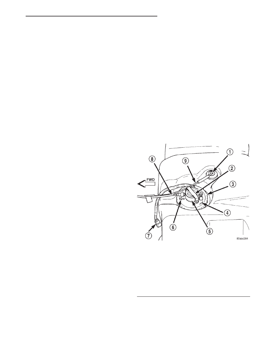
EVAPORATIVE EMISSION CONTROLS
TABLE OF CONTENTS
page
page
DESCRIPTION AND OPERATION
EVAPORATION CONTROL SYSTEM . . . . . . . . . . 23
ROLLOVER VALVE . . . . . . . . . . . . . . . . . . . . . . . 23
EVAP CANISTER . . . . . . . . . . . . . . . . . . . . . . . . . 24
DUTY CYCLE EVAP CANISTER PURGE
SOLENOID . . . . . . . . . . . . . . . . . . . . . . . . . . . . 24
LEAK DETECTION PUMP (LDP). . . . . . . . . . . . . . 24
CRANKCASE VENTILATION SYSTEM . . . . . . . . . 25
VEHICLE EMISSION CONTROL
INFORMATION (VECI) LABEL . . . . . . . . . . . . . . 26
DIAGNOSIS AND TESTING
VACUUM SCHEMATICS . . . . . . . . . . . . . . . . . . . . 26
REMOVAL AND INSTALLATION
EVAP CANISTER . . . . . . . . . . . . . . . . . . . . . . . . . 27
DUTY CYCLE EVAP CANISTER PURGE
SOLENOID . . . . . . . . . . . . . . . . . . . . . . . . . . . . 27
ROLLOVER VALVE(S) . . . . . . . . . . . . . . . . . . . . . 27
LEAK DETECTION PUMP (LDP). . . . . . . . . . . . . . 28
SPECIFICATIONS
TORQUE CHART . . . . . . . . . . . . . . . . . . . . . . . . . 28
DESCRIPTION AND OPERATION
EVAPORATION CONTROL SYSTEM
OPERATION
The evaporation control system prevents the emis-
sion of fuel tank vapors into the atmosphere. When
fuel evaporates in the fuel tank, the vapors pass
through vent hoses or tubes to a charcoal filled evap-
orative canister. The canister temporarily holds the
vapors. The Powertrain Control Module (PCM) allows
intake manifold vacuum to draw vapors into the com-
bustion chambers during certain operating condi-
tions.
All engines use a duty cycle purge system. The
PCM controls vapor flow by operating the duty cycle
EVAP purge solenoid. Refer to Duty Cycle EVAP
Canister Purge Solenoid.
When equipped with certain emissions packages, a
Leak Detection Pump (LDP) will be used as part of
the evaporative system for OBD II requirements.
Also refer to Leak Detection Pump.
NOTE: The evaporative system uses specially man-
ufactured lines/hoses. If replacement becomes nec-
essary, only use fuel resistant hose.
ROLLOVER VALVE
DESCRIPTION
The fuel tank is equipped with a rollover valve.
The valve is located on the top of the fuel tank (Fig.
1).
OPERATION
The rollover valve will prevent fuel flow through
the fuel tank vent (EVAP) hoses in the event of an
accidental vehicle rollover. The EVAP canister draws
fuel vapors from the fuel tank through this valve.
Fig. 1 Rollover Valve Location
1 – ROLLOVER VALVE
2 – RETAINER CLAMP
3 – LOCKNUT
4 – FUEL PUMP MODULE
5 – FUEL FILTER/FUEL PRESSURE REGULATOR
6 – ALIGNMENT ARROW
7 – PIGTAIL HARNESS
8 – FUEL SUPPLY TUBE
9 – EVAP CANISTER VENT LINE
XJ
EMISSION CONTROL SYSTEMS
25 - 23
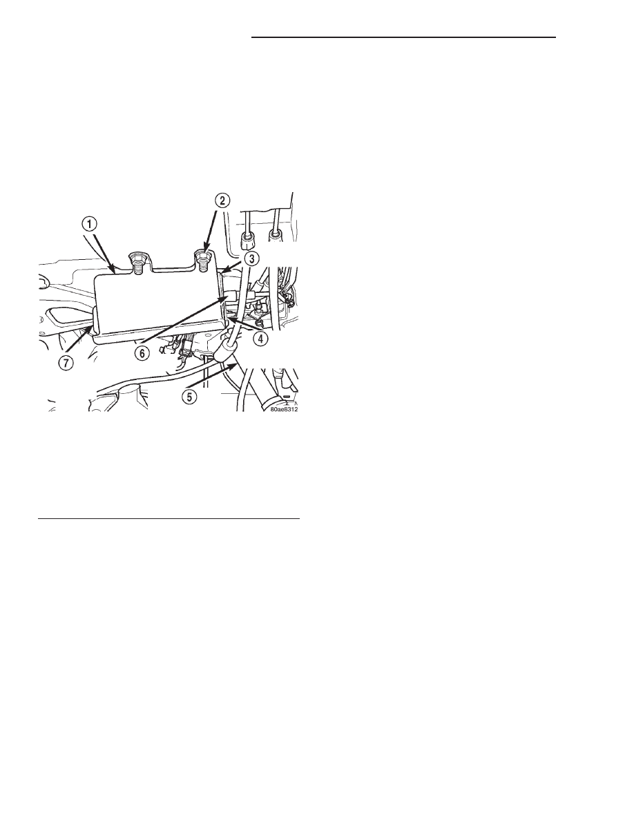
The valve cannot be serviced separately. If replace-
ment is necessary, the fuel tank must be replaced.
EVAP CANISTER
DESCRIPTION
A maintenance free, EVAP canister is used on all
vehicles. The EVAP canister is located under the left
side of vehicle near the front of the rear axle (Fig. 2).
OPERATION
The EVAP canister is filled with granules of an
activated carbon mixture. Fuel vapors entering the
EVAP canister are absorbed by the charcoal granules.
Fuel tank pressure vents into the EVAP canister.
Fuel vapors are temporarily held in the canister until
they can be drawn into the intake manifold. The duty
cycle EVAP canister purge solenoid allows the EVAP
canister to be purged at predetermined times and at
certain engine operating conditions.
DUTY CYCLE EVAP CANISTER PURGE
SOLENOID
OPERATION
The duty cycle EVAP canister purge solenoid (DCP)
regulates the rate of vapor flow from the EVAP can-
ister to the intake manifold. The Powertrain Control
Module (PCM) operates the solenoid.
During the cold start warm-up period and the hot
start time delay, the PCM does not energize the sole-
noid. When de-energized, no vapors are purged. The
PCM de-energizes the solenoid during open loop oper-
ation.
The engine enters closed loop operation after it
reaches a specified temperature and the time delay
ends. During closed loop operation, the PCM cycles
(energizes and de-energizes) the solenoid 5 or 10
times per second, depending upon operating condi-
tions. The PCM varies the vapor flow rate by chang-
ing solenoid pulse width. Pulse width is the amount
of time that the solenoid is energized. The PCM
adjusts solenoid pulse width based on engine operat-
ing condition.
LEAK DETECTION PUMP (LDP)
OPERATION
The Leak Detection Pump (LDP) is used only with
certain emission packages.
The LDP is a device used to detect a leak in the
evaporative system.
The pump contains a 3 port solenoid, a pump that
contains a switch, a spring loaded canister vent valve
seal, 2 check valves and a spring/diaphragm.
Immediately after a cold start, engine temperature
between 40°F and 86°F, the 3 port solenoid is briefly
energized. This initializes the pump by drawing air
into the pump cavity and also closes the vent seal.
During non-test test conditions, the vent seal is held
open by the pump diaphragm assembly which pushes
it open at the full travel position. The vent seal will
remain closed while the pump is cycling. This is due
to the operation of the 3 port solenoid which prevents
the diaphragm assembly from reaching full travel.
After the brief initialization period, the solenoid is
de-energized, allowing atmospheric pressure to enter
the pump cavity. This permits the spring to drive the
diaphragm which forces air out of the pump cavity
and into the vent system. When the solenoid is ener-
gized and de-energized, the cycle is repeated creating
flow in typical diaphragm pump fashion. The pump
is controlled in 2 modes:
PUMP MODE: The pump is cycled at a fixed rate
to achieve a rapid pressure build in order to shorten
the overall test time.
TEST MODE: The solenoid is energized with a
fixed duration pulse. Subsequent fixed pulses occur
when the diaphragm reaches the switch closure
point.
The spring in the pump is set so that the system
will achieve an equalized pressure of about 7.5 inches
of water.
When the pump starts, the cycle rate is quite high.
As the system becomes pressurized pump rate drops.
Fig. 2 EVAP Canister Location
1 – CANISTER MOUNTING BRACKET
2 – BRACKET NUTS (3)
3 – EVAP CANISTER
4 – CANISTER MOUNTING NUTS (2)
5 – L. R. SHOCK ABSORBER
6 – EVAP LINES/HOSES
7 – DOWEL PINS AND BUSHINGS (2)
25 - 24
EMISSION CONTROL SYSTEMS
XJ
DESCRIPTION AND OPERATION (Continued)
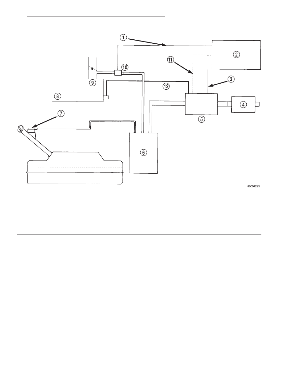
If there is no leak the pump will quit. If there is a
leak, the test is terminated at the end of the test
mode.
If there is no leak, the purge monitor is run. If the
cycle rate increases due to the flow through the
purge system, the test is passed and the diagnostic is
complete.
The canister vent valve will unseal the system
after completion of the test sequence as the pump
diaphragm assembly moves to the full travel position.
A typical system schematic is shown in (Fig. 3).
CRANKCASE VENTILATION SYSTEM
DESCRIPTION
All 2.5L 4–cylinder and 4.0L 6–cylinder engines
are equipped with a Closed Crankcase Ventilation
(CCV) system (Fig. 4) or (Fig. 5).
OPERATION
The CCV system performs the same function as a
conventional PCV system, but does not use a vacuum
controlled valve.
On 4.0L 6 cylinder engines, a molded vacuum tube
connects manifold vacuum to top of cylinder head
(valve) cover at dash panel end. The vacuum fitting
contains a fixed orifice of a calibrated size. It meters
the amount of crankcase vapors drawn out of the
engine.
On 2.5L 4 cylinder engines, a fitting on drivers
side of cylinder head (valve) cover contains the
metered orifice. It is connected to manifold vacuum.
A fresh air supply hose from the air cleaner is con-
nected to front of cylinder head cover on 4.0L
engines. It is connected to rear of cover on 2.5L
engines.
Fig. 3 Evaporative System Monitor Schematic—Typical
1 – DUTY CYCLE PURGE SOLENOID (DCPS) DRIVER
2 – POWERTRAIN CONTROL MODULE (PCM)
3 – 3-PORT SOLENOID DRIVER
4 – REMOTE FILTER
5 – COMBINED CANISTER VENT VALVE & LEAK DETECTION
PUMP
6 – CANISTER
7 – TANK ROLLOVER VALVE & VAPOR FLOW CONTROL
ORIFICE
8 – INTAKE MANIFOLD
9 – THROTTLE BODY
10 – DCPS
11 – SWITCH SIGNAL INPUT TO THE PCM
12 – ENGINE VACUUM LINE
XJ
EMISSION CONTROL SYSTEMS
25 - 25
DESCRIPTION AND OPERATION (Continued)
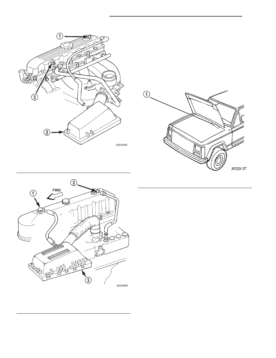
When the engine is operating, fresh air enters the
engine and mixes with crankcase vapors. Manifold
vacuum draws the vapor/air mixture through the
fixed orifice and into the intake manifold. The vapors
are then consumed during combustion.
VEHICLE EMISSION CONTROL INFORMATION
(VECI) LABEL
DESCRIPTION
All vehicles are equipped with a combined VECI
label. This label is located in the engine compart-
ment (Fig. 6).
OPERATION
The VECI label contains the following:
• Engine family and displacement
• Evaporative family
• Emission control system schematic
• Certification application
• Engine timing specifications (if adjustable)
• Idle speeds (if adjustable)
• Spark plug and gap
The label also contains an engine vacuum sche-
matic. There are unique labels for vehicles built for
sale in the state of California and the country of
Canada. Canadian labels are written in both the
English and French languages. These labels are per-
manently attached and cannot be removed without
defacing information and destroying label.
DIAGNOSIS AND TESTING
VACUUM SCHEMATICS
A vacuum schematic for emission related items can
be found on the Vehicle Emission Control Informa-
tion (VECI) label. For label location, refer to Vehicle
Emission Control Information (VECI) Label.
Fig. 4 CCV System—2.5L Engine—Typical
1 – AIR INLET FITTING
2 – AIR FILTER COVER
3 – FIXED ORIFICE FITTING
Fig. 5 CCV System—4.0L Engine—Typical
1 – AIR INLET FITTING
2 – FIXED ORIFICE FITTING
3 – AIR FILTER COVER
Fig. 6 VECI Label Location—Typical
1 – VECI LABEL
25 - 26
EMISSION CONTROL SYSTEMS
XJ
DESCRIPTION AND OPERATION (Continued)
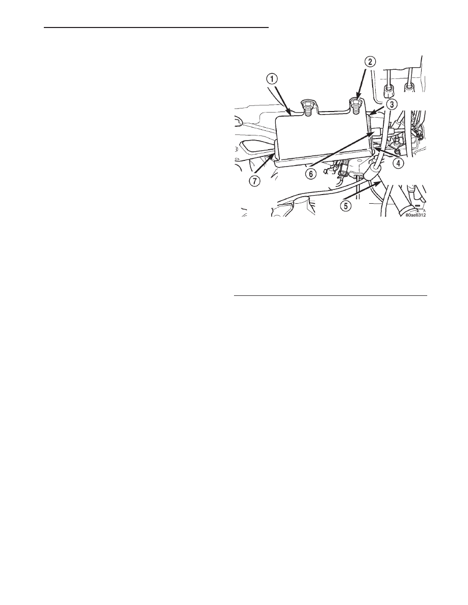
LEAK DETECTION PUMP (LDP)
Refer to the appropriate Powertrain Diagnostic
Procedures service manual for LDP testing proce-
dures.
CRANKCASE VENTILATION SYSTEM
TESTING/CLEANING
The Crankcase Ventilation (CCV) system performs
the same function as a conventional PCV system, but
does not use a vacuum controlled valve. A vacuum
fitting containing a fixed orifice of a calibrated size is
used. It meters the amount of crankcase vapors
drawn out of the engine.
(1) Check each CCV system tube (line) for leaks,
cracks, kinks or bends. Replace as necessary
(2) Disconnect each CCV tube..
(3) Blow compressed air through each tube and
check for blockage or restrictions. If cleaning is nec-
essary, spray a soapy-type all-purpose cleaner into
each component and blow out. After restriction is
cleared, rinse out component with clear water. Blow
water from component and install to vehicle. To pre-
vent
damage
to
plastic
components,
never
spray carburetor-type cleaner into any of the
plastic tubes or the fixed orifice fitting. Never
attempt to clean the fixed orifice fitting with a
metal object as calibration could be affected. If
fixed fitting cannot be cleared, replace it.
REMOVAL AND INSTALLATION
EVAP CANISTER
The EVAP canister is located under left side of
vehicle near front of rear axle (Fig. 7).
REMOVAL
(1) Disconnect vacuum hoses/lines at EVAP canis-
ter. Note location of lines before removal.
(2) Remove EVAP canister and mounting bracket
assembly from body (3 nuts).
(3) Remove canister from mounting bracket (2
nuts).
INSTALLATION
(1) Position
canister
into
canister
mounting
bracket. Align 2 canister dowel pins into rubber
bushings.
(2) Install 2 canister nuts and tighten to 5 N·m (45
in. lbs.) torque.
(3) Position canister and bracket assembly to body.
(4) Install 3 nuts and tighten to 43 N·m (32 ft.
lbs.) torque.
(5) Connect vacuum hoses/lines at EVAP canister.
DUTY CYCLE EVAP CANISTER PURGE
SOLENOID
REMOVAL
The solenoid attaches to a bracket located in right-
rear side of engine compartment (Fig. 8) or (Fig. 9).
The top of the solenoid has the word UP or TOP on
it. The solenoid will not operate properly unless it is
installed correctly.
(1) Disconnect electrical wiring connector at sole-
noid.
(2) Disconnect vacuum harness at solenoid.
(3) Remove solenoid and its support bracket.
INSTALLATION
(1) Install EVAP canister purge solenoid and its
mounting bracket to cowl panel.
(2) Tighten bolt to 5 N·m (45 in. lbs.) torque.
(3) Connect vacuum harness and wiring connector.
ROLLOVER VALVE(S)
The rollover valves(s) are/is molded into the fuel
tank and are not serviced separately. If replacement
is necessary, the fuel tank must be replaced. Refer to
Fuel Tank Removal/Installation.
Fig. 7 EVAP Canister Location
1 – CANISTER MOUNTING BRACKET
2 – BRACKET NUTS (3)
3 – EVAP CANISTER
4 – CANISTER MOUNTING NUTS (2)
5 – L. R. SHOCK ABSORBER
6 – EVAP LINES/HOSES
7 – DOWEL PINS AND BUSHINGS (2)
XJ
EMISSION CONTROL SYSTEMS
25 - 27
DIAGNOSIS AND TESTING (Continued)
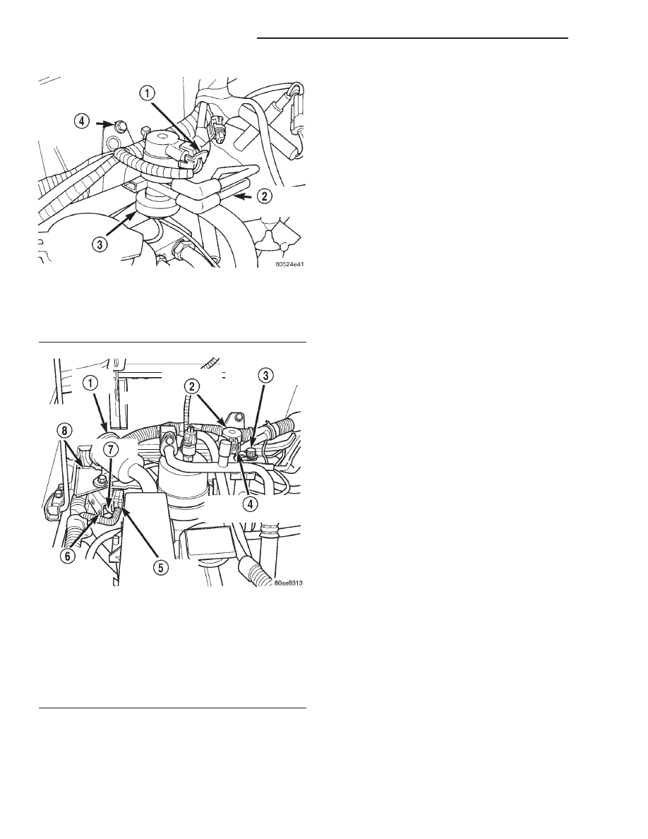
LEAK DETECTION PUMP (LDP)
The LDP is located in the right-rear side of engine
compartment (Fig. 9). The LDP filter is located above
the LDP (Fig. 9). The LDP and LDP filter are
replaced (serviced) as one unit.
REMOVAL
(1) Carefully remove hose at LDP filter.
(2) Remove LDP filter mounting bolt and remove
from vehicle.
(3) Carefully remove vapor/vacuum lines at LDP.
(4) Disconnect electrical connector at LDP.
(5) Remove 2 LDP mounting screws (Fig. 9) and
remove from vehicle.
INSTALLATION
(1) Install LDP to mounting bracket. Tighten
screws to 1 N·m (11 in. lbs.) torque.
(2) Install LDP filter to mounting bracket. Tighten
bolt to 7 N·m (65 in. lbs.) torque.
(3) Carefully install vapor/vacuum lines to LDP,
and install hose to LDP filter. The vapor/vacuum
lines and hoses must be firmly connected.
Check the vapor/vacuum lines at the LDP, LDP
filter and EVAP canister purge solenoid for
damage or leaks. If a leak is present, a Diagnos-
tic Trouble Code (DTC) may be set.
(4) Connect electrical connector to LDP.
SPECIFICATIONS
TORQUE CHART
Description
Torque
EVAP Canister Mounting Nuts (canister-to-
mounting bracket) . . . . . . . . . 5 N·m (45 in. lbs.)
EVAP Canister Mounting Bracket Nuts (mounting
bracket-to-body) . . . . . . . . . . 43 N·m (32 in. lbs.)
EVAP Canister Purge Solenoid Bracket-to-Body
Mounting Bolt . . . . . . . . . . . . 5 N·m (45 in. lbs.)
LDP Mounting Screws . . . . . . . . 1 N·m (11 in. lbs.)
Fig. 8 EVAP Canister Purge Solenoid (Without LDP)
1 – ELECTRICAL CONNECTOR
2 – VACUUM HARNESS
3 – PURGE SOLENOID
4 – MOUNTING BOLT
Fig. 9 EVAP Canister Purge Solenoid (With LDP)
1 – LDP FILTER
2 – EVAP SOLENOID
3 – EVAP SYSTEM TEST PORT
4 – EVAP SOLENOID ELEC. CONNECTOR
5 – LDP ELEC. CONNECTOR
6 – LDP MOUNTING SCREWS (2)
7 – LDP
8 – LDP MOUNTING BRACKET
25 - 28
EMISSION CONTROL SYSTEMS
XJ
REMOVAL AND INSTALLATION (Continued)
Document Outline
- EMISSION CONTROL SYSTEMS
- ON-BOARD DIAGNOSTICS
- DESCRIPTION AND OPERATION
- EVAPORATIVE EMISSION CONTROLS
- ON-BOARD DIAGNOSTICS
Wyszukiwarka
Podobne podstrony:
Ustawa z dnia 25 06 1999 r o świadcz pien z ubezp społ w razie choroby i macierz
Cwiczenia 23 25 2007
Wykład 25
Wykład12 Sieć z protokołem X 25 i Frame Relay
zwierzaczki 25
25 Wyklad 1 Dlaczego zwiazki sa wazne
wyklad 2012 10 25 (Struktury systemów komputerowych)
Wykład10a Sieć z protokołem X 25 i Frame Relay
prognozowanie i symulacje wyklad (25 str)
25 26
21 25
25 Pilot, Mechanizmy prowadzace do zroznicowania genetycznego miedzy populacjami w obrebie gatunku (
KM W 25 lekkie konst met stud
2 25 Spajanie różnorodnych materiałów
obrazki 25
1996 06 25 1147
25 Prawo Bankowe
więcej podobnych podstron