
Initial Print Date: 12/04
Table of Contents
Subject
Page
E65 Car Access System . . . . . . . . . . . . . . . . . . . . . . . . . . . . . . . . . . . . . . .4
Ignition/Starter Switch (ZAS) . . . . . . . . . . . . . . . . . . . . . . . . . . . . . . . . . . . . .7
Start/Stop Button . . . . . . . . . . . . . . . . . . . . . . . . . . . . . . . . . . . . . . . . . . . . . . .8
CAS Control Unit . . . . . . . . . . . . . . . . . . . . . . . . . . . . . . . . . . . . . . . . . . . . . . .8
“Ignition Key” (Remote Controls) . . . . . . . . . . . . . . . . . . . . . . . . . . . . . . . .10
Starting the Engine . . . . . . . . . . . . . . . . . . . . . . . . . . . . . . . . . . . . . . . . .13
Switching off the Engine . . . . . . . . . . . . . . . . . . . . . . . . . . . . . . . . . . . . .14
Incorrect Operation and "Emergency On" . . . . . . . . . . . . . . . . . . . . . .14
Automatic Release with Missing Transponder . . . . . . . . . . . . . . . . . .14
Terminal Control . . . . . . . . . . . . . . . . . . . . . . . . . . . . . . . . . . . . . . . . . . . . . .15
Terminal Status in Vehicle Electrical System . . . . . . . . . . . . . . . . . . . . . .15
Hardware Redundancy . . . . . . . . . . . . . . . . . . . . . . . . . . . . . . . . . . . . . . . . .15
Announcement of Terminal 15w “Wake-up” . . . . . . . . . . . . . . . . . . . . . .16
Announcement of Terminal 15 "on" . . . . . . . . . . . . . . . . . . . . . . . . . . . . .16
Terminal 50 (Engine Starting) . . . . . . . . . . . . . . . . . . . . . . . . . . . . . . . . . . .17
Starter Motor Disabling . . . . . . . . . . . . . . . . . . . . . . . . . . . . . . . . . . . . . .18
Actuation Time of Terminal 50 . . . . . . . . . . . . . . . . . . . . . . . . . . . . . . . .18
Terminal 50 E
(Electronics-Signal of Starting Request to the DME) . . . . . . . . . . . .19
Terminal 50 L (Load-Starter Solenoid) . . . . . . . . . . . . . . . . . . . . . . . . .19
E65 Car Access System
Revision Date:

Subject
Page
Auto-Park, Interlock and Shiftlock Functions . . . . . . . . . . . . . . . . . . . . . .19
EWS Functions . . . . . . . . . . . . . . . . . . . . . . . . . . . . . . . . . . . . . . . . . . . . . . .20
Central Body Electronics Master Functions . . . . . . . . . . . . . . . . . . . .21
Central Locking System Master - CAS . . . . . . . . . . . . . . . . . . . . . . . . . . .21
Window Control System Master - CAS . . . . . . . . . . . . . . . . . . . . . . . . . .21
Remote Control Services (FBD) . . . . . . . . . . . . . . . . . . . . . . . . . . . . . . . . .21
Redundant Data Storage . . . . . . . . . . . . . . . . . . . . . . . . . . . . . . . . . . . . . . .21
Vehicle Order . . . . . . . . . . . . . . . . . . . . . . . . . . . . . . . . . . . . . . . . . . . . . . . . .22
CBS (Condition Based Service) Data . . . . . . . . . . . . . . . . . . . . . . . . . . . .23
Vehicle Mileage Storage . . . . . . . . . . . . . . . . . . . . . . . . . . . . . . . . . . . . . . .23
Workshop Hints . . . . . . . . . . . . . . . . . . . . . . . . . . . . . . . . . . . . . . . . . . . . . . .23
Installation of a New CAS . . . . . . . . . . . . . . . . . . . . . . . . . . . . . . . . . . . .23

3
E65 Car Access System
E65 Car Access System
Model: E65, E66
Production: All
After completion of this module you will be able to:
• Understand the function and operation of the Car Access System
• Understand EWS functions of CAS
• Diagnose faults within the Car Access System
E65 Car Access System
The Car Access System (CAS) controls access to the vehicle by controlling the master
functions of the central locking system. It also controls the terminal statuses (KL R, KL
15, KL 50) via the ignition/starting button. The EWS functions are also integrated into
the CAS which allows for starting of the engine.
The CAS is a new development and combines the components previously installed in
separate control units or systems:
• Ignition/starter switch
• Electronic vehicle immobilization (EWS)
• Functions of the central body electronics (ZKE).
The major development goals were increased convenience and a new operating concept.
4
E65 Car Access System
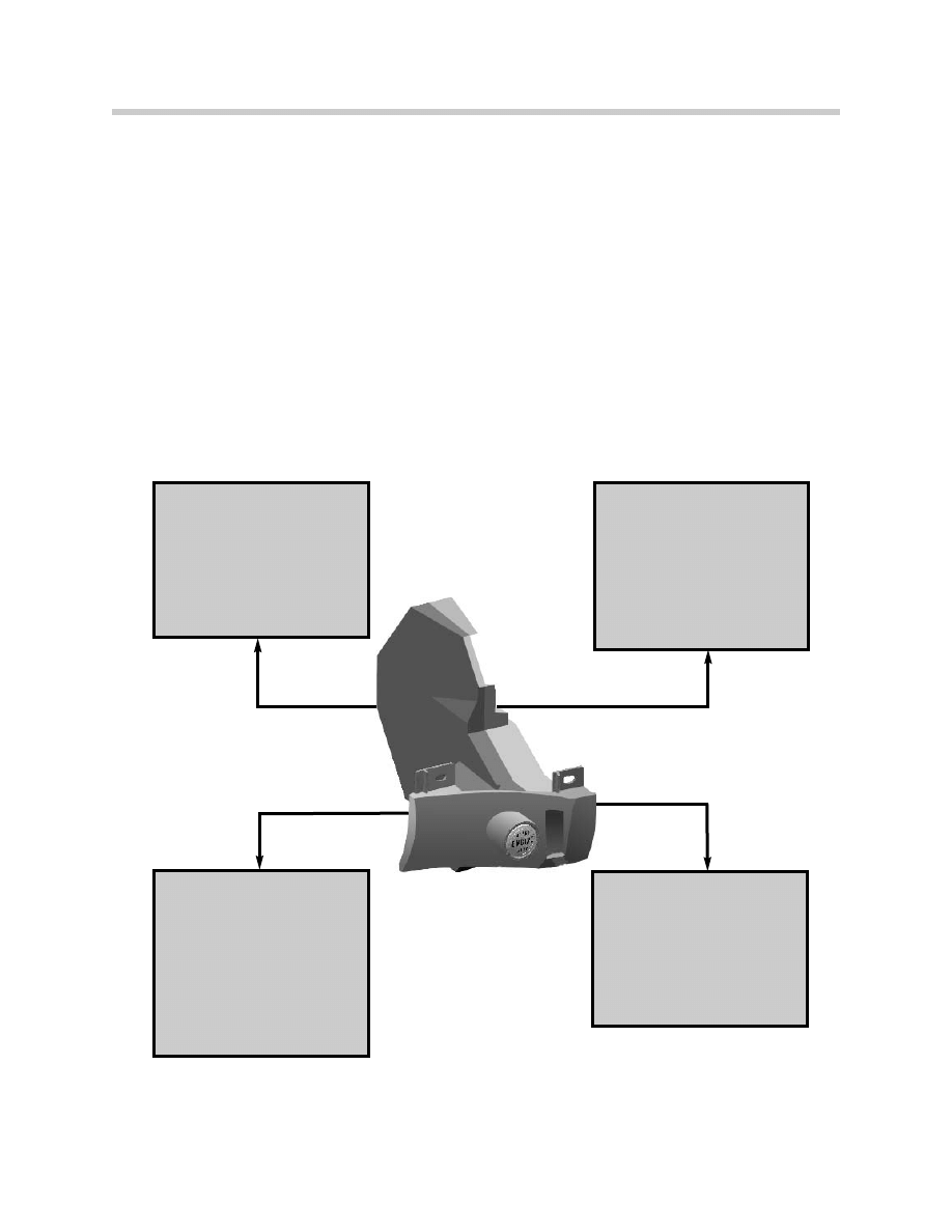
Terminal Status Master:
• KLR, KL15, KL50
• Hardwire outputs
• Bus telegrams
Gateway Functions:
• Gateway between
K-CAN-S and
K-CAN-P
EWS Functions:
• Remote control
identification
• Rolling code ISN
• EWS 3.3
Central Body
Electronics:
• Central Locking
controller (main)
• Window master
• FBD functions
5
E65 Car Access System
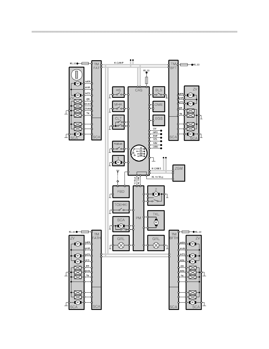
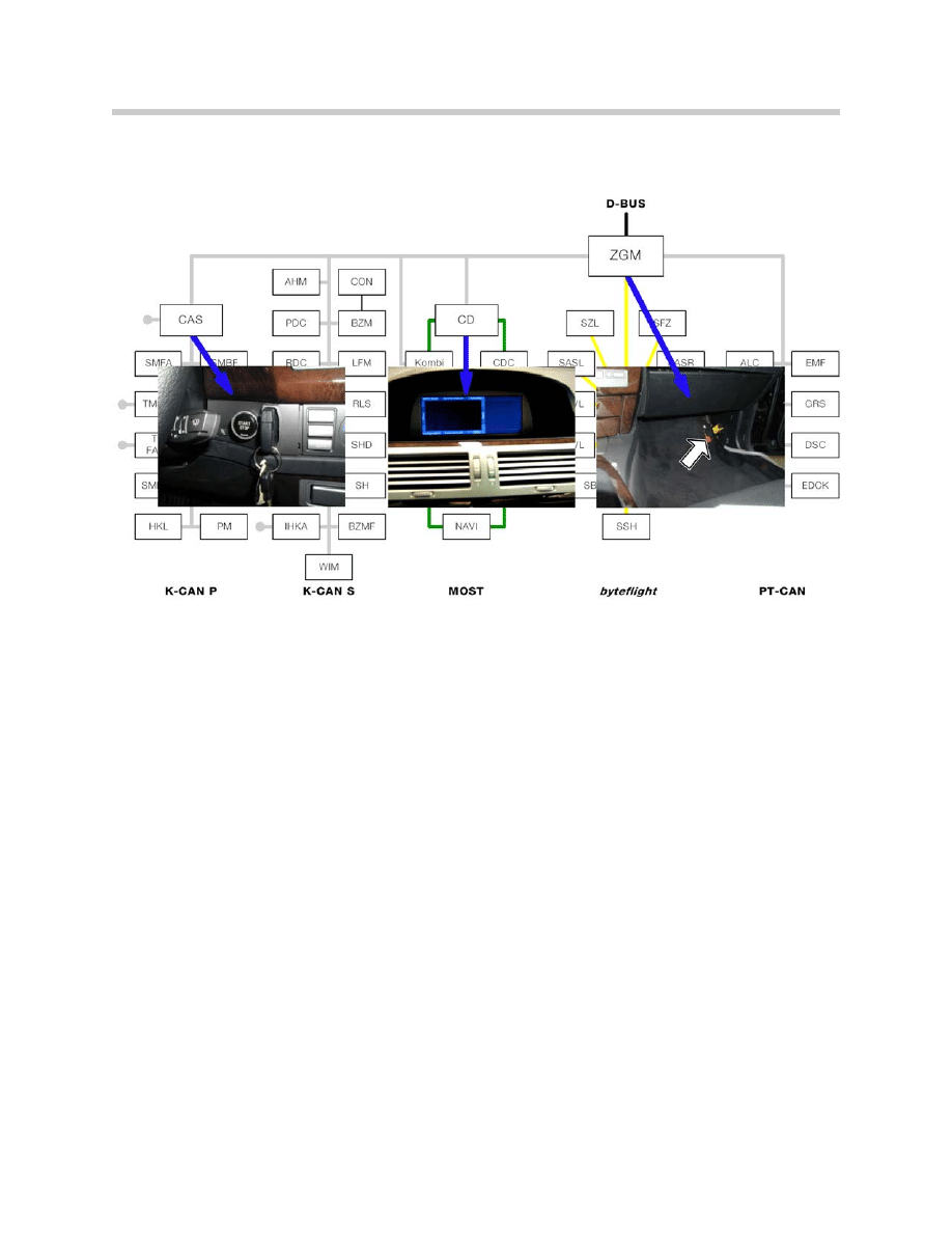
CAS System Overview

6
E65 Car Access System
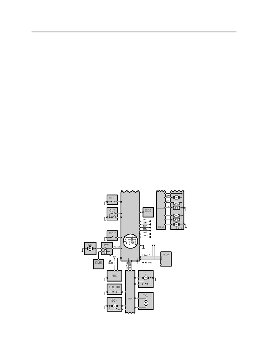
Legend for CAS Overview
Acronym
Description
Acronym
Description
M1
Starter
LM
Lamp Module
KL15w
Terminal 15 Wake-up
MER
Unlock motor
KL30
Terminal 30
MHK
Hood contact
KL87
Terminal 87
MVR
Locking motor
BLS
Brake light switch
MZS
Central locking motor
CAS
Car Access System
OBD
On-board diagnosis
CLT
Central locking button
PM
Power Module
DME
Digital Motor Electronics
SCA
Soft close automatic
ER
Unlocking
SZL
Steering Column Switch Center
EGS
Electronic Transmission Control
TK
Door Contact
EKP
Electric Fuel Pump
TKL
Fuel Filler Door
FBD
Remote Control System
TMBFT
Door Module passenger side
GRL
Trunk Light
TMBFTH
Door Module passenger side rear
GRS
Rotation rate sensor
TMFAT
Door Module, driver’s side
HS
Hotel Switch
TMFATH
Door Module, driver’s side rear
IVM
Integrated Voltage Supply Module
TOEHK
Trunk release button, outside
K-CAN-P
K-CAN Periphery
TOEHKI
Trunk release button, inside
KiSi
Child Proof door lock
ZGM
Central Gateway Module
ZV
Central Locking System
7
E65 Car Access System
Components
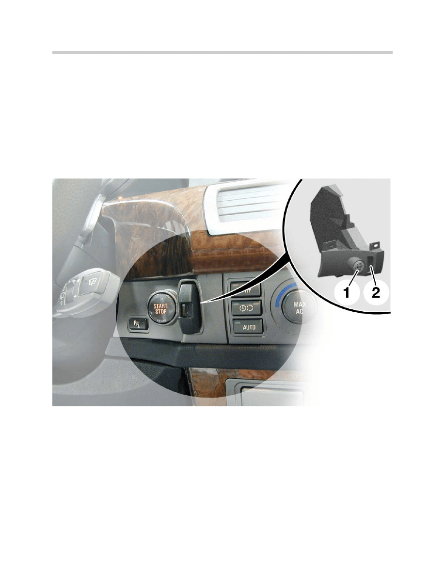
Ignition/Starter Switch (ZAS)
The ignition/starter switch is the electro-mechanical part of the CAS and consists of:
• An ignition switch with an electromagnetic lock.
• A start/stop button.
• A coil for powering and communicating with the EWS transponder and for
charging the battery in the remote controls.
The ignition lock/start button (ZAS) is located in the instrument panel between the instru-
ment cluster and the control display at the level of the trim strips.
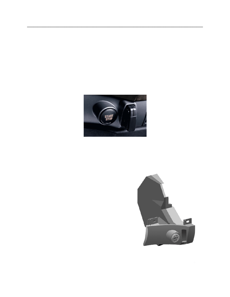
Light emitting diodes (LEDs) are integrated into the ignition/start button for illumination.
The LEDs:
• Illuminate the start/stop button and the ignition lock/remote control receiver.
• Are switched on by the CAS from the "wake-up" signal.
• The LEDs are switched on as long as the bus is active (Useful for diagnosis of the
bus sleep mode: when the LEDs light up, the bus is active).
1. Start/Stop Button
2. Ignition Lock/Remote
Control Receiver
8
E65 Car Access System
Using the ignition/starter switch (ZAS) and the remote controls:
• The vehicle is started.
• The different terminal statuses are selected (KL30, KL R, KL 15, KL 50).
Start/Stop Button
The various terminals are no longer actuated by turning an ignition key, but instead by
touching the start/stop button. The vehicle is also started and shut-off with the start/stop
button.
CAS Control Unit
The CAS control unit is the electronic part of the CAS/ZAS. The CAS is connected via
the K-CAN Periphery with:
• The door modules
• The seat modules
• The Power Module
The higher-level connection to the entire vehicle is
carried out via the K-CAN System.
All outputs from the CAS are designed
• With semiconductor technology
• Are short-circuit-proof to ground and B+
• Are fully diagnosis-capable
9
E65 Car Access System
The CAS is the Gateway between the K-CAN System and K-CAN Periphery Bus.
The CAS directly controls the functions:
• Radio remote control (FBD)
• Terminal control
• Electronic immobilizer (EWS)
• Starter-motor control
• Engine starting (ignition/starter switch)
The CAS control unit has the master functions for:
• The central locking system
• The window functions
The CAS has data storage functions:
• The mileage reading is stored in the instrument cluster (KOMBI) and in the CAS.
When one of the two control units is replaced, the kilometer reading of the vehicle is
transferred from the other control unit to the new control unit.
• Vehicle Order (successor to ZCS) is stored in the Lamp Module (LM) and the CAS.
10
E65 Car Access System
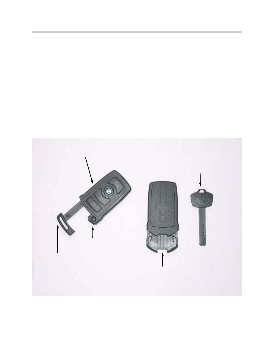
“Ignition Key” (Remote Controls)
The “keys” are the component that represents the access and driving authorization for
the vehicle.
All keys (with the exception of the key integrated in the remote control) contain the
transponder for EWS.
The delivery specification of the vehicle are:
• 2 coded remote controls with integrated mechanical key.
• A reserve key (also individually coded) with an adapter for the ZAS (ignition lock).
Note: Since no ignition switch in the ordinary sense is installed, the term vehi-
cle keys is also no longer used, but instead "remote controls")
Remote control
Release button for mechanical key
Adapter for reserve key
Reserve key
Integrated mechanical key

11
E65 Car Access System
Remote Controls
The power supply for the remote controls is provided by a non-replaceable re-chargeable
battery.
• Charging: The battery is charged when the remote control is engaged in the ignition
switch. Charging takes place via a 125 kHz interface in the ignition switch.
• Monitoring: The re-chargeable battery voltage is monitored by the remote control.
At low voltage a Check Control message is output to the instrument cluster.
Each remote control is individually coded. As a result, different memory functions can be
saved for each key: for example, seat adjustment, outside mirror adjustment, steering col-
umn adjustment etc.
The operating radio frequency of the remote controls in the U.S. is now 868.4Mhz.
No initialization procedure is required for the Remote Controls, once the CAS has recog-
nized the key as valid it is automatically initialized.
Mechanical Key Integrated into the Remote Control
A key is pushed into the housing of the remote control. The key is purely mechanical and
contains no transponder function for the EWS.
The key is used to emergency unlock the drivers door and trunk and also to lock and
unlock the center storage box (hotel switch inside) and transmission emergency park
release cable. To release the key, push the small button at the end of the remote control
and slide the key out.
Reserve Key with Adapter
The delivery specification also includes a reserve key with an adapter for the ZAS. The
reserve key is considerably smaller than the remote controls, enabling it to be easily car-
ried in a wallet.
The reserve key consists of an integrated transponder and a mechanically cut plastic key.
An adapter is required to push the narrow, flat reserve key into the slot and to engage it.
The adapter should be stored in the vehicles tool kit.
A reserve key with the adapter has full access and driving authorization for the vehicle.
Key Management
The CAS control unit can manage a maximum of 10 valid vehicle keys. Three keys are
initialized during vehicle assembly, two remote controls and one reserve key.
The customer can order 7 additional keys if necessary.

12
E65 Car Access System
Principle of Operation
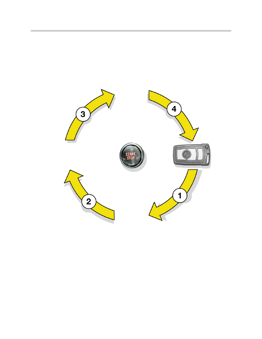
Inserting, Locking and Releasing Remote Controls in Ignition Switch
The vehicle can be started with the remote controls or with the reserve key:
1. Inserting: push the remote control into the ignition switch.
2. Pressing the remote control: the sensor detects a user request to lock the remote
control in the ignition switch.
3. Identification of the transponder by the CAS.
4. Locking the remote control in the ignition switch: when the remote control is recog-
nized as authorized, the electro-mechanical removal lock is activated.
The remote control is mechanically fixed in place (locked). Locking of the remote control
in the ignition switch is verified by a hall sensor in the CAS.
This ensures that the vehicle can be locked with the key in the case of a system failure.
5. Terminal R "on": after the remote control is locked in the ignition switch, terminal R is
automatically switched on.
Automatic Ejection of a Remote Control
A remote control recognized as invalid cannot be locked (e.g. the key of another vehicle).If
the transponder is invalid, the remote control will be pushed out.
Removing the Remote Control
The remote control can only be removed when the vehicle is stopped (below 1km/h) and
the engine is switched off.
If these conditions are met, then the remote control can be removed in any terminal sta-
tus by pressing the remote control. When pressed, the sensor in the CAS detects a
request for release.
The CAS control unit actuates the electro-mechanical removal lock. The remote control
is pushed out with spring force. After releasing the removal lock, the CAS is always in the
position terminal R "off."
The remote control may also be “comfort released” by pressing the start/stop button for
longer than 2 seconds after shutting off the engine.
13
E65 Car Access System
Terminal Selection
The terminal statuses are selected when the brakes are not actuated by touching the
start/stop button. A valid key must be locked in place. The terminal statuses are run
through as follows:
Ignition "off" (terminal 30) > terminal R > terminal 15 > terminal R > ignition "off"
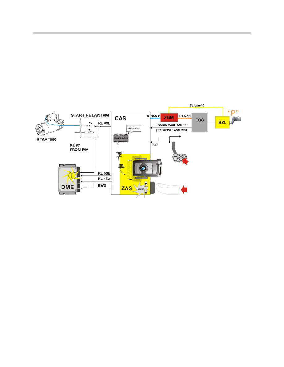
Starting the Engine
The vehicle engine can be started from all terminal statuses when:
• A valid remote control is inserted and locked in the ignition switch
• The brake pedal is actuated.
If the brake-light switch is defective or disconnected, an actuation of the brakes is detect-
ed by the DSC control unit via the brake pressure sensor. Also, the P or N position of the
transmission is detected via the EGS (TCM).
Insert Remote
Control
KLR “ON”

14
E65 Car Access System
Switching off the Engine
The vehicle engine is switched off when the vehicle is stopped and the start/stop button
is pressed.
If the start/stop button is pressed for longer than 2 seconds, the vehicle engine is
switched off and then the key is automatically released and pushed out with spring pres-
sure ("convenience off").
After the vehicle engine is switched off, the CAS is in KL "R" (operational readiness for
windshield wipe, radio, airbag).
Incorrect Operation and "Emergency On"
To ensure the safety of the vehicle in the case of an accidental engine shutdown during
driving, the "Emergency On" function is available.
An engine shutdown during driving can be caused by accidentally pressing the start/stop
button (the start/stop button must be pressed for at least 1 second or 3 times consecu-
tively).
The "Emergency On" function enables the starter to be actuated again without brake
operation at a vehicle speed above 5 km/h (3mph). The "Emergency On" function also
prevents terminal R from being switched off during driving.
Automatic Release with Missing Transponder
To protect against damage, tampering or incorrect operation, the remote control in the
ignition switch is automatically released when:
• The transponder is no longer detected with terminal R "on".
• The vehicle is stopped.
• The transmission is in the park position.
The authentication (validity test) of the transponder is carried out every 500 milliseconds
within the first 10 seconds. Then the authentication takes place every 3 seconds.

15
E65 Car Access System
Terminal Control
The CAS generates the terminal statuses for the vehicle when the start/stop button is
operated.
The terminals can only be connected when the remote control in the ignition switch is
authenticated (recognized as valid) and the "key valid" signal is generated by the
transponder in the CAS.
Terminal Status in Vehicle Electrical System
The terminal status generated by the CAS for the vehicle is transmitted to the following
buses every 100 milliseconds:
• K-CAN S
• K-CAN P
• PT-CAN
• MOST
• byteflight
The following statuses are output as telegrams:
• Status of terminal R
• Terminal 15 wake-up
• Status of terminal 15
• Status of terminal 50
• Valid key inserted
Hardware Redundancy
For safety reasons the terminal status of the terminal 15 outputs is redundant (via a hard-
ware switch in the CAS).
Notes:

16
E65 Car Access System
Announcement of Terminal 15w “Wake-up”
The CAS and the ZGM (Central Gateway Module) are the only control units that can
wake up the vehicle electrical system.
The control units on the K-CAN S, K-CAN P, byteflight and MOST are awakened by the
network management (NWM) on the respective bus.
The control units on the PT-CAN are woken up via a high signal on the activation wire for
terminal 15 wake-up. If a PT-CAN control unit receives the change in voltage "low-high"
at the wake-up input, the control unit begins with reception and the evaluation of the
messages from the PT-CAN.
Two modules (ZGM and the Power Module receive KL 15 wake-up as a hardwired input
from the CAS in addition to the network management wake-up signal over the bus.
Announcement of Terminal 15 "on"
For safety reasons certain control units and sensors are not only informed via the bus sig-
nal about terminal 15, but also have a direct hardwired output from the CAS.
The CAS provides ten KL 15 outputs for hardwire redundancies:
• Ignition coil relay: the output for the ignition coil relay is equipped with an overrun for
maintaining OBD-relevant emission values (Emissions optimization). When KL15 is
switched "off" the ignition coils are not switched off until after a run-on time so that
any fuel still injected is burned.
• GRS (Rotation/transverse acceleration rate sensor for DSC)
• LM/BLS (Lamp Module, brake-light switch)
• SBSR (Satellite B-pillar right, fuel pump)
• SZL (Steering Column Switching Center, selector lever transmission)
• OBD socket KL15 supply (On-Board Diagnosis)
• Rear seat heating (has no bus line)
• Three are reserved for future use
17
E65 Car Access System
Terminal 50 (Engine Starting)
Terminal 50 is actuated by pressing the start/stop button.
Engine start-up and the related terminal change are carried out as soon as the start/stop
button is pressed for at least 50 milliseconds.
The following conditions are needed to complete the start sequence:
• Remote control is valid and locked (transponder authentication).
• Brake operation: the brake is either detected via the direct wiring of the brake-light
switch or redundantly via the CAN signal from the DSC. An incorrect brake signal
from a defective or disconnected brake-light switch is detected as a "plausibility
fault" as soon as the brake pressure is greater than 10 bar. If one of the two signals
is missing, a Check Control message is sent. The engine start-up is permitted when
the start/stop button is pressed again.
• Selector lever of automatic transmission in position P and N. The position of the
selector lever is detected via the direct P signal or via a CAN signal. The engine can
be started when at least one of these signal is present.
• No start-repeat lock present (start-repeat lock is activated at an engine speed above
1000 rpm).
If these conditions are not met, the starter-motor disabling circuit is activated. The engine
cannot be started.

18
E65 Car Access System
Starter Motor Disabling
The starter disable circuit is used to protect the starter. The starter cannot be engaged
with an already running engine.
The starter disable is carried out after the actuation of the starter solenoid has been
ended.
The following situations will enable the starter disable function of the CAS:
• No "brakes actuated" signal: if no "brakes actuated" signal is output within a maxi-
mum of 200 milliseconds after the start/stop button is pressed, the engine start-up
is aborted again. If only one of the two redundantly output brake operation signals is
received, then the engine can be started.
• No continuous "brakes actuated" signal: if during the starting procedure the brakes
are not continuously actuated, the engine start-up is aborted again.
• Time-out expired: the maximum operating period of the starter is 21 seconds.
• Selector lever in invalid position: outside P or N.
• The engine speed is greater than 1000 rpm. The DME (ECM) signals "status
engine running."
• Short circuit/overloading detection of the starter by the CAS.
Actuation Time of Terminal 50
The monitored actuating times of terminal 50 protects the starter against overloading.
The actuation times of terminal 50 are:
• A maximum of 21 seconds. A repetition is possible immediately.
• The actuation time is reduced for each repetition by 2 seconds until the minimum
actuation time of 3 seconds is reached.
• If the start/stop button is pressed for longer than the preceding actuation time, the
actuation time is increased by 2 seconds again (up to a maximum of 21 seconds).
Notes:

19
E65 Car Access System
Terminal 50 E (Electronics-Signal of Starting Request to the DME)
Terminal 50 E is provided to signal the starting request by the CAS to the DME.
Terminal 50 L (Load-Starter Solenoid)
Terminal 50 L is an input to the IVM to switch on the starter solenoid.
Auto-Park, Interlock and Shiftlock Functions
Auto-Park, Interlock and Shiftlock are safety functions.
Auto-Park and Interlock are CAS functions. Shiftlock is an EGS function.
• Auto-Park: When the remote control is removed from the ignition switch, the park
position of the selector lever is automatically engaged. The "Auto-Park" function is
programmed in the EGS.
• Interlock: The selector lever is locked in the park position until a valid remote control
can be detected in the ignition switch.
• Shiftlock: the selector lever can only be moved out of the positions P or N with the
brakes actuated.
For safety reasons the EGS supplies the "transmission range and park position" signal
redundantly. The EGS supplies two signals:
• The transmission position P via a direct, hard-wired cable (between the transmission
and the CAS) for deactivation.
• The transmission range status via the message "gear status" as a redundancy (sig-
nal path: EGS - ZGM - CAS).
Notes:
20
E65 Car Access System
EWS Functions
The EWS function is also integrated into the CAS control unit. The transponder authenti-
cation is similar to the method used by EWS 3.3. The encoding process was changed
compared to that of the previous versions (to increase security against tampering).
After a start request from the start/stop button, starting may continue if the following
conditions are met:
• Valid transponder detected
• Brakes actuated
• Selector lever in position P or N
The EWS sends a message (ISN) with a random code to the DME. To start the engine,
the DME (ECM) enables the ignition and fuel injection. The fuel pump is actuated via the
SBSR (satellite B-pillar right) as soon as a corresponding speed signal is sent on the bus
by the DME (ECM).
The starter is actuated independently of the EWS ISN using the terminal 50 signal. If the
starter turns and the engine fails to start, there may be a problem with communication
between the DME (ECM) and EWS.

21
E65 Car Access System
Central Body Electronics Master Functions
Central Locking System Master - CAS
The CAS contains all of the programmed logics for the Central Locking system.
Window Control System Master - CAS
The CAS contains all of the programmed logics for the window control system.
Remote Control Services (FBD)
The CAS is responsible for receiving the remote control request signals from the FBD
receiver and placing requests for operation over the bus line.
Redundant Data Storage
The CAS is one of three control units in the E65 to store important vehicle specific data.
The CAS is responsible for storing:
• The full 17 digit VIN Number (Only the last 7 digits are stored in codeable modules)
• Vehicle Order (FA)
• Total mileage
• CBS (Conditioned Based Service) Data
Redundantly, the full 17 digit VIN and the Vehicle Order (FA) are stored in the LM and the
mileage is stored in the KOMBI. CBS data is stored in the Remote Controls.
Notes:

22
E65 Car Access System
Vehicle Order
The Vehicle Order (FA-Fahzeugauftrag) replaces the central coding code (ZCS) used up
until now. The Vehicle Order describes the current status of a vehicle (following produc-
tion and in case of a change in the vehicle equipment).
The Vehicle Order is formed for each vehicle individually from the factory assembly order.
The length of the vehicle order varies depending on the amount of vehicle equipment.
During first initialization at the factory, the Vehicle Order is entered into the CAS. It is also
stored redundantly in the LM (Lamp Module). If the CAS is replaced or retrofitted in the
workshop, the Vehicle Order must be re-entered or added to the CAS control unit.
Content of the Vehicle Order:
• Vehicle Identification Number (full 17 digit VIN)
• Series (E65)
• Model key (Digits 4-7 of the VIN)
• Time criterion (Production date: MM/YY)
• Paint code (4 digit paint code)
• Upholstery code (4 digit code)
• Assembly Number (ZusBau: prog. part # for powertrain)
• E word (Additions to the standard series not in the SA)
• HO word (center installed options using 3 digit option codes: not used yet)
• Special-equipment codes (3 digit SA #’s, up to 100 possible entries)
The FA may be read out and printed using the E65 programming software (CIP). Any
options installed at the BMW center will be able to be registered and input using the FA
editor function.
23
E65 Car Access System
CBS (Condition Based Service) Data
The CBS (Condition Based Service) data are saved in:
• Remote controls (key)
• The EEPROM of the CAS
• Kombi
The CAS reads the data from the vehicle electrical system (DME (ECM), DSC,
KOMBI etc.).
If terminal 15 is switched off, the CAS saves the data into the remote control.
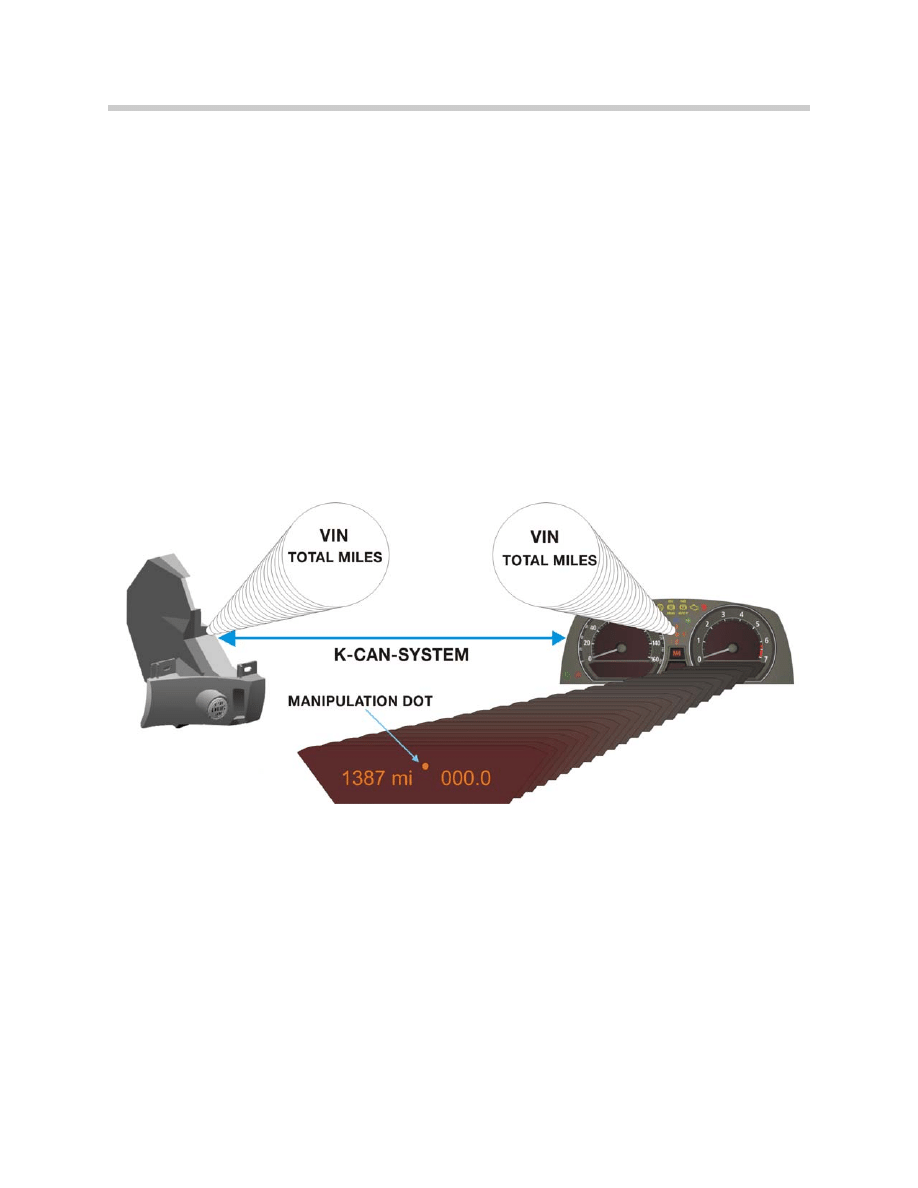
Vehicle Mileage Storage
To prevent the vehicle-specific data from being lost when the instrument cluster is
replaced, they are stored redundantly in the CAS. Mileage is only transferred from
the KOMBI to the CAS when the stored VINs match.
Workshop Hints
Installation of a New CAS
A new CAS must ordered on a VIN-specific basis (key number, vehicle identification
number, standard equipment) and installed in the relevant vehicle.
The new CAS must then be coded using the BMW DISplus, GT-1 or MoDiC III.
Alignment of the CAS and DME (ECM) must also be carried out, only then can the
engine be started.
Installation of a used CAS control unit is of limited use, as it will not be possible to open
the vehicle using the original remote control or start the engine.

24
E65 Car Access System
Replacement of Both CAS and Instrument Cluster (two new components)
Where possible, this should be avoided, as the current mileage reading and all the CBS
data are irretrievably lost!
If both control units have to be replaced at one time, the following installation sequence is
recommended:
1. Replacement of the instrument cluster
2. Coding of vehicle identification number
3. Terminal 15 OFF/ON (possible data transfer)
4. Replacement of the CAS
5. Coding of vehicle identification number
6. Terminal 15 OFF/ON
When terminal 15 is switched on again, the manipulation dot is extinguished. The com-
munication between the instrument cluster and the CAS for redundant data storage is
now available.
Remember, when replacing a CAS or KOMBI:
• The manipulation dot is set if the vehicle identification number in the CAS is differ-
ent from the vehicle identification number in the instrument cluster.
• If the vehicle identification numbers are different, data exchange takes place in the
working memory of the instrument cluster; however, no data is stored permanently.
• The instrument cluster adopts the data from the CAS if the CAS has a higher
mileage reading than the instrument cluster and the vehicle identification numbers
match.
• The CAS adopts the data from the instrument cluster if the instrument cluster has a
higher mileage reading and the vehicle identification numbers match.
• The mileage is transferred from the instrument cluster to the CAS every 10 km (6
miles) of the trip. If at least 24 hours have elapsed between switching terminal 15
on and off, then another download is performed, regardless of the distance driven.

25
E65 Car Access System
Diagnosis
Diagnosis of the various functions of the CAS are carried out using the Diagnosis
Program of the DISplus, GT-1 or MoDiC. The Test Modules are automatically selected
based on the faults stored or can be selected on the basis of a customer complaint.
The test modules are developed based on a specific function and may not deal exclusive-
ly with only the CAS.
“Expert Mode” diagnosis is available in the Control Unit Functions mask. The available
functions are:
• Identification page
• Read fault memory
• Clear fault memory
• Diagnosis Requests
-Transponder data
-Programming data
-Internal hall sensors
-Inputs
-Terminal Statuses
-Remote Controls
-Remote Control battery status
Blocking Remote Controls
If a Remote Control is lost, it can be blocked using the Test Module “Key Bar/Release”
located under the “Service Functions” menu.
• Insert another valid and released remote control.
• Identify the lost Remote Control: To identify a lost Remote Control, it is necessary
that all physically present remote controls are presented to the CAS.
• Read out the numbers of all Remote Controls via the CAS.
• Determine the number of the lost Remote Control from the available key numbers.
• Block the lost Remote Control with the Test Module.
If the Remote Control is found again it can be enabled again in the same way.

26
E65 Car Access System
Workshop Exercise - Car Access System
Using an instructor designated vehicle, perform a complete short test on the vehicle.
Access CAS in the “control unit functions” screen.
Go to status requests.
What is the key # and personalization number of the current key in use?
What is the difference between the key # and the personalization number?
Go to the “service functions” menu and access the “enable/disable” key test module.
Locate extra key and disable.
Can the vehicle be started with the extra key after disable procedure?
Re-enable key and re-check.
Can the vehicle be started with the re-enabled key?
Check key status screen.
How many keys are enabled?
Notes:

27
E65 Car Access System
Workshop Exercise - Diagnosis
Using an instructor designated vehicle, perform a complete vehicle short test.
Diagnose complaint as directed by instructor. Complete worksheet using the proper
“Complaint, Cause and Correction” format.
Vehicle:
Chassis #:
Production Date:
Complaint:
Cause:
Correction:

28
E65 Car Access System
Classroom Exercise - Review Questions
1.
What are the principle functions that the CAS is responsible for?
2.
What is the ZAS? How can the ZAS be helpful in determining if the CAS is
asleep?
3.
Between which two Bus lines does the CAS act as a “Gateway”?
4.
What is required before the “wallet” key can be used in the ZAS?
5.
What is the frequency of the Remote Controls for the E65?

29
E65 Car Access System
6.
How can the customer cycle between KL R and KL 15 without starting the
engine? How are the different control modules aware that a terminal has changed
state?
7.
What important vehicle data is stored in the CAS? Where else in the vehicle is this
data stored redundantly?
8.
What would occur if the CAS and Instrument Cluster were replaced
simultaneously? (Explain Answer)
9.
Where it the data for Condition Based Service (CBS) stored?
10.
After pressing the start button to start the vehicle, what other conditions must be
observed by the CAS in order to start the vehicle?
Document Outline
- Main Menu
- Intro to Advanced Body Electronics
- E65 Power Module
- E65 Car Access System
- E65 Instrument Cluster
- E65 iDrive Driving Area
- E65 iDrive Comfort Area
- E65 Audio System
- E65 Navigation System
- E65 Telephone
- E65 Speech Processing System
- E65 Central Body Electronics
- E65 Remote Control Services
- E65 Automatic Trunk Lid Lift
- E65 Wiping Washing
- E65 Seat, Mirror, Steering Wheel
- E65 Lighting Systems
- E65 Driveaway Protection
- E65 Park Distance Control
- E65 Active Cruise Control
- Voltage Supply and Bus Systems
- 5 & 6 Series Body Electronics
- E60 Driver Information Systems
- E60 Communication Systems
- Car Communication Computer
- Head-Up Display
- Glossary
Wyszukiwarka
Podobne podstrony:
05 E65 Car Access System
03b E70 Car Access System 3
12 E65 Speech Processing System
04d E65 Speech Processing System
system zarządzania bazami danych access, Pomoce naukowe, studia, informatyka
car Audio, Projektowanie systemu audio, bass tylko jaki
car Audio, Montaż systemu przedniego, Montaż systemu przedniego
car Audio, Montaż systemu przedniego, Montaż systemu przedniego
Konfiguracja CISCO - Access Restrictions, Systemy Operacyjne i Sieci Komputerowe
02b Organizacja systemu ubezpieczeń społecznych
09 E65 Audio System
06 E65 66 Comfort Access
04a E65 Audio System
Prosty system car audio
10 E65 Navigation System
więcej podobnych podstron