
TECHNICAL NOTE 3385A
JE0X
FAULT FINDING
J66 Phase 1'
from September 2000
AIR CONDITIONING
VDIAG N°: 04
DISCHARGE LAMP
VDIAG N°: 09
IMMOBILISER
INSTRUMENT PANEL
PASSENGER COMPARTMENT CONNECTION UNIT
77 11 293 842
"The repair methods given by the manufacturer in this document are based on the
technical specifications current when it was prepared.
The methods may be modified as a result of changes introduced by the manufacturer
in the production of the various component units and accessories from which his
vehicles are constructed."
JULY 2000
All copyrights reserved by Renault.
EDITION ANGLAISE
Copying or translating, in part or in full, of this document or use of the service part
reference numbering system is forbidden without the prior written authority of Renault.
© RENAULT 2000

Contents
Page
62
80
82
83
87
AIR CONDITIONING
Preliminary
62-1
Interpretation of faults
62-2
Conformity check
62-40
Customer complaints
62-42
Fault finding chart
62-43
DISCHARGE LAMP
Preliminary
80-1
Interpretation of faults
80-2
Conformity check
80-7
Customer complaints
80-8
Fault finding chart
80-9
IMMOBILISER
Preliminary
82-1
Interpretation of faults
82-2
Conformity check
82-7
Customer complaints
82-8
Fault finding chart
82-9
INSTRUMENT PANEL
Preliminary
83-1
Conformity check
83-2
PASSENGER COMPARTMENT
CONNECTION UNIT
Preliminary
87-1
Interpretation of faults
87-2
Conformity check
87-21
Status interpretation
87-24

AIR CONDITIONING
Fault finding - Introduction
62
162
AIR CONDITIONING
Fault finding - Introduction
GENERAL APPROACH TO FAULT FINDING:
– Use of one of the fault finding tools to identify the system equipping the vehicle (to read the computer
family, the program number, the vdiag, etc.).
– Finding the "Fault finding" documents corresponding to the system identified.
– Inclusion of information contained in the introductory sections.
– Reading the faults stored in the computer memory and using the "Interpretation of faults" section of the
documents.
Reminder: Each fault is interpreted for a particular type of storage (fault present, fault stored, fault present
or stored). The checks defined for handling each fault are therefore only to be performed if the fault stated
by the fault finding tool is interpreted in the document for its type of storage. The storage type should be
considered when using fault finding tool following ignition switch-off and switch-on.
If a fault is interpreted when it is stated to be "stored", the conditions for application of the fault finding
appear in the "NOTES" box. When the conditions are not satisfied, use the fault finding to check the circuit
of the faulty part since the fault is no longer present on the vehicle. Perform the same operation when a
fault is stated as "stored" by the fault finding tool but is only interpreted in the documentation for a
"present" fault.
– Perform the conformity check (appearance of possible incorrect operations not yet stated by the system's
self diagnosis procedure) and apply the associated fault finding strategy according to results.
– Validation of the repair (disappearance of the reason for the complaint by the customer).
– Use of the fault finding strategy for each "Customer complaint" if the problem persists.
This document introduces the generic fault finding strategy applicable to all "Air conditioning" computers
(relevant section: 60 25 315 003, n˚ Vdiag: 04).
A Technical Note "Fault Finding Special Features" is available for each vehicle fitted with this computer /
this function. It covers all the fault finding special features in this document for the vehicle concerned.
This "Special Features" Note completes and cancels the information provided in the "Generic" fault
finding Note.
To carry out the fault finding strategy on this system, it is essential to have the following items available:
– The "Generic Fault Finding" Technical Note,
– The "Fault Finding Special Features" Technical Note for the vehicle,
– The wiring diagram for the operation of the vehicle concerned,
– The tools listed under the heading "Special tooling required".
62-1
AIR CONDITIONING
Diagnostics - Fault Interpretation
62
Diagnostics - Fault Interpretation
DF 003
PRESENT
OR
MEMORISED
Coolant temperature sensor circuit
C0.1
:
Short circuit to + 12 volts or to +5 volts or open circuit
CC.0
:
Short circuit to earth
NOTES
None
C0.1
NOTES
None
Ensure continuity and insulation against + 12 volts or against + 5 volts of the connection between:
computer connector
computer connector
computer connector
track C11 track 1
track C11 track A
track C11 track 4
coolant temperature sensor connector (L7X)
coolant temperature sensor connector (F4R)
coolant temperature sensor connector (G9T,
F9Q)
Check that the probe resistance is not zero or equal to infinity.
Check the connectors on the computer connector, the temperature sensor connector and the R262 B (black)
connection track 6.
If the fault persists after these checks, replace the coolant temperature sensor.
CC.0
NOTES
None
Ensure insulation against earth of the connection between:
computer connector
computer connector
computer connector
track C11 track 1
track C11 track A
track C11 track 4
coolant temperature sensor connector (L7X)
coolant temperature sensor connector (F4R)
coolant temperature sensor connector (G9T,
F9Q)
Check that the probe resistance is not zero or equal to infinity.
Check the connectors on the computer connector, the temperature sensor connector and the R262 B (black)
connection track 6.
If the fault persists after these checks, replace the coolant temperature sensor.
AFTER REPAIR
Erase fault memory.
62-2
AIR CONDITIONING
Diagnostics - Fault Interpretation
62
62-3
DF 007
PRESENT
OR
MEMORISED
Internal temperature sensor circuit
C0.1
:
Short circuit to + 12 volts or to +5 volts or open circuit
CC.0
: Short circuit to earth
NOTES
None
C0.1
NOTES
None
Ensure continuity and insulation against + 12 volts or against + 5 volts of the connection between:
computer connector track A19
track 3 internal temperature sensor connector
Ensure insulation against + 12 volts of the connection between:
computer connector track A5
track 4 internal temperature sensor connector
Test the connections on the computer connector.
If the fault persists after these checks, replace the coolant temperature sensor.
CC.0
NOTES
None
Ensure insulation against earth of the connection between:
computer connector track A19
track 3 internal temperature sensor connector
Check that the sensor resistance is approximately 2.2 kΩ at 25˚C.
Test the connections on the computer connector and the internal temperature sensor.
If the fault persists after these checks, replace the coolant temperature sensor.
AFTER REPAIR
Erase fault memory.

AIR CONDITIONING
Diagnostics - Fault Interpretation
62
62-4
DF 008
PRESENT
OR
MEMORISED
External temperature sensor circuit
C0.1
:
Short circuit to + 12 volts or to +5 volts or open circuit
CC.0
: Short circuit to earth
NOTES
None
C0.1
NOTES
None
Ensure continuity and insulation against + 12 volts or against + 5 volts of the connection between:
computer connector track C10
track 6
left external rear view mirror external
temperature probe connector
Ensure insulation against + 12 volts of the connection between:
computer connector track C14
track 5
left external rear view mirror external
temperature probe connector
Test the connections on the computer connector.
If the fault persists after these checks, replace the external temperature probe.
CC.0
NOTES
None
Ensure insulation against earth of the connection between:
computer connector track C10
track 6
left external rear view mirror external
temperature probe connector
Check that the probe resistance is approximately 3.1 kohms at 20˚C.
Test the connections on the computer connector.
If the fault persists after these checks, replace the external temperature probe.
AFTER REPAIR
Erase fault memory.

AIR CONDITIONING
Diagnostics - Fault Interpretation
62
62-5
DF 044
PRESENT
OR
MEMORISED
Driver control circuit
CO.1
:
Open circuit or short circuit
NOTES
If DF044 is CC deal also with DF045.
CO.1
NOTES
None
Ensure continuity and insulation against earth, or against + 12 volts, of the connection between:
computer connector track A10
track 5
driver control panel connector
Test the connectors on the computer and the driver control panel.
If the fault persists after these checks, replace the driver control panel.
AFTER REPAIR
Erase fault memory.
AIR CONDITIONING
Diagnostics - Fault Interpretation
62
62-6
DF 045
PRESENT
OR
MEMORISED
Passenger control circuit
CO.1
:
Open circuit or short circuit
NOTES
If DF045 is CC deal also with DF044.
CO.1
NOTES
None
Ensure continuity and insulation against earth, or against + 12 volts, of the connection between:
computer connector track A20
track 5
passenger control panel connector
Test the connectors on the computer and the driver control panel.
If the fault persists after these checks, replace the driver control panel.
AFTER REPAIR
Erase fault memory.

AIR CONDITIONING
Diagnostics - Fault Interpretation
62
62-7
DF 047
PRESENT
OR
MEMORISED
Passenger mixing motor
CC :
Short
circuit
NOTES
The fault is declared present following operation of the passenger mixing motor.
CC
NOTES
None
Check that the mixing motor resistance is not zero or equal to infinity.
Test the connectors on the computer and the passenger mixing motor.
Ensure insulation against + 12 V of the following connections:
computer connector track B2
track 4
passenger mixing motor connector (track 6 in DD).
computer connector track B3
track 6
passenger mixing motor connector (track 4 in DD).
Repair if necessary.
Ensure the following connections are insulated to earth:
computer connector track B2
track 4
passenger mixing motor connector (track 6 in DD).
computer connector track B3
track 6
passenger mixing motor connector (track 4 in DD).
Repair if necessary.
AFTER REPAIR
Erase fault memory.

AIR CONDITIONING
Diagnostics - Fault Interpretation
62
62-8
DF 048
PRESENT
OR
MEMORISED
Driver mixing motor
CC :
Short
circuit
NOTES
The fault is declared present following operation of the driver mixing motor.
CC
NOTES
None
Check that the mixing motor resistance is not zero or equal to infinity.
Test the connectors on the computer and the driver mixing motor.
Ensure insulation against + 12 V of the following connections:
computer connector track B4
track 6
driver mixing motor connector (track 4 in DD).
computer connector track B5
track 4
driver mixing motor connector (track 6 in DD).
Repair if necessary.
Ensure the following connections are insulated to earth:
computer connector track B4
track 6
driver mixing motor connector (track 4 in DD).
computer connector track B5
track 4
driver mixing motor connector (track 6 in DD).
Repair if necessary.
AFTER REPAIR
Erase fault memory.
AIR CONDITIONING
Diagnostics - Fault Interpretation
62
62-9
DF 052
PRESENT
OR
MEMORISED
Left recycling circuit
CC :
Short
circuit
NOTES
The fault is declared present following operation of the air recycling.
CC
NOTES
None
Test the connectors on the computer and the left recycling motor.
Ensure insulation against + 12 volts of the connection between:
computer connector track A9
track 1
left external air inlet motor connector
computer connector track A8
track 3
left external air inlet motor connector
Repair if necessary.
Ensure insulation against earth of the connection between:
computer connector track A9
track 1
left external air inlet motor connector
computer connector track A8
track 3
left external air inlet motor connector
Repair if necessary.
AFTER REPAIR
Erase fault memory.

AIR CONDITIONING
Diagnostics - Fault Interpretation
62
62-10
DF 053
PRESENT
OR
MEMORISED
Right recycling circuit
CC :
Short
circuit
NOTES
The fault is declared present following operation of the air recycling.
CC
NOTES
None
Test the connectors on the computer and the right recycling motor.
Ensure insulation against + 12 volts of the connection between:
computer connector track A6
track 3
right external air inlet motor connector
computer connector track A7
track 1
right external air inlet motor connector
Repair if necessary.
Ensure insulation against earth of the connection between:
computer connector track A6
track 3
right external air inlet motor connector
computer connector track A7
track 1
right external air inlet motor connector
Repair if necessary.
AFTER REPAIR
Erase fault memory.

AIR CONDITIONING
Diagnostics - Fault Interpretation
62
62-11
DF 055
PRESENT
OR
MEMORISED
Heated rear window relay
CC.1 : Short circuit to + 12 volts
NOTES
The fault is declared present when the de-icing function is required.
CC.1
NOTES
None
Test the connections on the relay mounting and the computer connector.
Ensure insulation against + 12 volts of the connection between:
computer connector track C1
track 2 heated rear screen relay carrier
Repair if necessary.
AFTER REPAIR
Erase fault memory.

AIR CONDITIONING
Diagnostics - Fault Interpretation
62
62-12
DF 056
PRESENT
OR
MEMORISED
Air conditioning control relay
CC.1 : Short circuit to + 12 volts
NOTES
The fault is declared present following operation of the air conditioning.
CC.1
NOTES
None
Test the connections on the relay mounting and the computer connector.
Ensure insulation against + 12 volts of the connection between:
computer connector track B9
track 16
passenger compartment connection unit 26
track yellow B connector
Repair if necessary.
AFTER REPAIR
Erase fault memory.

AIR CONDITIONING
Diagnostics - Fault Interpretation
62
62-13
DF 057
PRESENT
OR
MEMORISED
Injection circuit
AC
CC.0 : Short circuit to earth
NOTES
The fault is declared present following operation of the air conditioning.
CC.0
NOTES
None
Ensure insulation against earth of the connection between:
computer connector track C4
track 9
R262 connection D connector
connection D connector R262
track 46
F4R motor injection computer connector
track 40
L7X motor injection computer connector
track 37
F9Q motor injection computer connector
track G4
G9T motor injection computer connector
Repair if necessary.
AFTER REPAIR
Erase fault memory.
AIR CONDITIONING
Diagnostics - Fault Interpretation
62
62-14
DF 060
PRESENT
OR
MEMORISED
Right timing motor potentiometer circuit
C0.1
:
Short circuit to + 12 volts or to + 5 volts or open circuit
CC.0
:
Short circuit to earth
NOTES
The fault is declared present following operation of the right timing motor.
C0.1
NOTES
None
Check that the potentiometer resistance is not zero or equal to infinity.
Test the connectors on the computer and the right timing motor.
Ensure continuity and insulation against + 12 volts or against + 5 volts of the connection between:
computer connector track B11
track 2
right timing motor connector
computer connector track A14
track 2
right timing motor connector
Repair if necessary.
CC.0
NOTES
None
Check that the potentiometer resistance is not zero or equal to infinity.
Test the connectors on the computer and the right timing motor.
Ensure insulation against earth of the connection between:
computer connector track B11
track 2
right timing motor connector
computer connector track B15
track 3
right timing motor connector
Repair if necessary.
AFTER REPAIR
Erase fault memory.

AIR CONDITIONING
Diagnostics - Fault Interpretation
62
62-15
DF 061
PRESENT
OR
MEMORISED
Left timing motor potentiometer circuit
C0.1
:
Short circuit to + 12 volts or to + 5 volts or open circuit
CC.0
: Short circuit to earth
NOTES
The fault is declared present following operation of the left timing motor.
C0.1
NOTES
None
Check that the potentiometer resistance is not zero or equal to infinity.
Test the connectors on the computer and the left timing motor.
Ensure continuity and insulation against + 12 volts or against + 5 volts of the connection between:
computer connector track B12
track 2
left timing motor connector
computer connector track A15
track 1
left timing motor connector
Repair if necessary.
CC.0
NOTES
None
Check that the potentiometer resistance is not zero or equal to infinity.
Test the connectors on the computer and the left timing motor.
Ensure insulation against earth of the connection between:
computer connector track B12
track 2
left timing motor connector
computer connector track B16
track 3
left timing motor connector
Repair if necessary.
AFTER REPAIR
Erase fault memory.

AIR CONDITIONING
Diagnostics - Fault Interpretation
62
62-16
DF 062
PRESENT
OR
MEMORISED
Potentiometer or sensors + 5 volts supply
CC.0
:
Short circuit to earth
NOTES
If DF060 DF061 DF083 DF084 are also present deal with DF062 as a priority.
CC.0
NOTES
None
Check insulation against earth of connections A11, A12, A13, B15 and B16.
Repair if necessary.
AFTER REPAIR
Erase fault memory.

AIR CONDITIONING
Diagnostics - Fault Interpretation
62
62-17
DF 063
PRESENT
OR
MEMORISED
Potentiometer or sensor earth
CC.1
:
Short circuit to + 12 volts or + 5 volts
NOTES
If DF007 DF008 DF060 DF061 DF075 DF076 DF080 DF083 DF084 are present deal
with DF063 as a priority.
CC.1
NOTES
None
Check insulation at + 12 volts of connections A5, A14, A15, A16 and C14.
Repair if necessary.
AFTER REPAIR
Erase fault memory.

AIR CONDITIONING
Diagnostics - Fault Interpretation
62
62-18
DF 064
PRESENT
OR
MEMORISED
Head height air distribution key
DEF
:
Key locked
NOTES
The fault is declared present when pressing on one of the driver control keys for more
than 60 seconds.
Test the driver control keys.
If the fault persists after these checks, replace the driver control.
AFTER REPAIR
Erase fault memory.

AIR CONDITIONING
Diagnostics - Fault Interpretation
62
62-19
DF 065
PRESENT
OR
MEMORISED
Foot height air distribution key
DEF
:
Key locked
NOTES
The fault is declared present when pressing on one of the driver control keys for more
than 60 seconds.
Test the driver control keys.
If the fault persists after these checks, replace the driver control.
AFTER REPAIR
Erase fault memory.
AIR CONDITIONING
Diagnostics - Fault Interpretation
62
62-20
DF 066
PRESENT
OR
MEMORISED
Foot height / windscreen distribution key
DEF
:
Key locked
NOTES
The fault is declared present when pressing on one of the driver control keys for more
than 60 seconds.
Test the driver control keys.
If the fault persists after these checks, replace the driver control.
AFTER REPAIR
Erase fault memory.

AIR CONDITIONING
Diagnostics - Fault Interpretation
62
62-21
DF 067
PRESENT
OR
MEMORISED
De-icing / demisting key
DEF
:
Key locked
NOTES
The fault is declared present when pressing on one of the driver control keys for more
than 60 seconds.
Test the driver control keys.
If the fault persists after these checks, replace the driver control.
AFTER REPAIR
Erase fault memory.
AIR CONDITIONING
Diagnostics - Fault Interpretation
62
62-22
DF 068
PRESENT
OR
MEMORISED
Air conditioning key
DEF
:
Key locked
NOTES
The fault is declared present when pressing on one of the driver control keys for more
than 60 seconds.
Test the driver control keys.
If the fault persists after these checks, replace the driver control.
AFTER REPAIR
Erase fault memory.

AIR CONDITIONING
Diagnostics - Fault Interpretation
62
62-23
DF 069
PRESENT
OR
MEMORISED
Recycling key
DEF
:
Key locked
NOTES
The fault is declared present when pressing on one of the driver control keys for more
than 60 seconds.
Test the driver control keys.
If the fault persists after these checks, replace the driver control.
AFTER REPAIR
Erase fault memory.

AIR CONDITIONING
Diagnostics - Fault Interpretation
62
62-24
DF 070
PRESENT
OR
MEMORISED
Ventilation setting key
1.DEF : (-) key locked
2.DEF : (+) key locked
NOTES
The fault is declared present when pressing on one of the driver control keys for more
than 60 seconds.
Test the driver control keys.
If the fault persists after these checks, replace the driver control.
AFTER REPAIR
Erase fault memory.

AIR CONDITIONING
Diagnostics - Fault Interpretation
62
62-25
DF 071
PRESENT
OR
MEMORISED
Automatic air conditioning key
DEF
:
Key locked
NOTES
The fault is declared present when pressing on one of the driver control keys for more
than 60 seconds.
Test the driver control keys.
If the fault persists after these checks, replace the driver control.
AFTER REPAIR
Erase fault memory.
AIR CONDITIONING
Diagnostics - Fault Interpretation
62
62-26
DF 072
PRESENT
OR
MEMORISED
Driver temperature setting key
1.DEF :
(-) key locked
2.DEF :
(+) key locked
NOTES
The fault is declared present when pressing on one of the driver control keys for more
than 60 seconds.
Test the driver control keys.
If the fault persists after these checks, replace the driver control.
AFTER REPAIR
Erase fault memory.

AIR CONDITIONING
Diagnostics - Fault Interpretation
62
62-27
DF 073
PRESENT
OR
MEMORISED
Passenger temperature setting key
1.DEF : (-) key locked
2.DEF : (+) key locked
NOTES
The fault is declared present when pressing on one of the driver control keys for more
than 60 seconds.
Test the driver control keys.
If the fault persists after these checks, replace the driver control.
AFTER REPAIR
Erase fault memory.

AIR CONDITIONING
Diagnostics - Fault Interpretation
62
62-28
DF 075
PRESENT
OR
MEMORISED
Right air distribution motor locked
NOTES
The fault is declared present following operation of the distribution motor.
Check that the air distribution motor is not locked mechanically by an external object.
Feed directly the air distribution motor.
Change the motor if it is not functioning.
AFTER REPAIR
Erase fault memory.

AIR CONDITIONING
Diagnostics - Fault Interpretation
62
62-29
DF 076
PRESENT
OR
MEMORISED
Left air distribution motor locked
NOTES
The fault is declared present following operation of the distribution motor.
Check that the air distribution motor is not locked mechanically by an external object.
Feed directly the air distribution motor.
Change the motor if it is not functioning.
AFTER REPAIR
Erase fault memory.
AIR CONDITIONING
Diagnostics - Fault Interpretation
62
62-30
DF 077
PRESENT
OR
MEMORISED
Internal temperature probe microturbine circuit
CO
: Open circuit
CC.0 : Short circuit to earth
NOTES
None
CO
NOTES
None
Ensure the continuity of the following connection:
computer connector track B1
track 1 internal temperature sensor connector
Test the connections on the computer connector and the internal temperature sensor connector.
If the fault persists after these checks, replace the internal temperature sensor.
CC.0
NOTES
None
Ensure insulation against earth of the connection between:
computer connector track B1
track 1 internal temperature sensor connector
If the fault persists after these checks, replace the internal temperature sensor.
AFTER REPAIR
Erase fault memory.

AIR CONDITIONING
Diagnostics - Fault Interpretation
62
62-31
DF 078
PRESENT
OR
MEMORISED
Driver insolation sensor circuit
CC.1
:
Short circuit to + 12 volts or + 5 volts
NOTES
If DF079 DF083 are also present, deal with DF078 as a priority.
CC.1
NOTES
None
Check insulation of the connection:
computer connector track A17 (A18 in DD)
track 2 insolation sensor
Repair if necessary.
If the fault persists, replace the insolation sensor.
AFTER REPAIR
Erase fault memory.

AIR CONDITIONING
Diagnostics - Fault Interpretation
62
62-32
DF 079
PRESENT
OR
MEMORISED
Passenger insolation sensor circuit
CC.1
:
Short circuit to + 12 volts or + 5 volts
NOTES
If DF078 DF080 are also present, deal with DF079 as a priority.
CC.1
NOTES
None
Check insulation of the connection:
computer connector track A18 (A17 in DD)
track 3 insolation sensor
Repair if necessary.
If the fault persists, replace the insolation sensor.
AFTER REPAIR
Erase fault memory.

AIR CONDITIONING
Diagnostics - Fault Interpretation
62
62-33
DF 080
PRESENT
OR
MEMORISED
Locked driver mixing motor
NOTES
The fault is declared present when mixing motor operation is required.
Check that the mixing motor is not locked mechanically by an external object.
Feed directly the mixing motor to test functioning.
Change the motor if it is not functioning.
AFTER REPAIR
Erase fault memory.

AIR CONDITIONING
Diagnostics - Fault Interpretation
62
62-34
DF 081
PRESENT
OR
MEMORISED
Locked passenger mixing motor
NOTES
The fault is declared present when mixing motor operation is required.
Check that the mixing motor is not locked mechanically by an external object.
Feed directly the mixing motor to test functioning.
Change the motor if it is not functioning.
AFTER REPAIR
Erase fault memory.

AIR CONDITIONING
Diagnostics - Fault Interpretation
62
62-35
DF 082
PRESENT
OR
MEMORISED
Passenger compartment ventilation motor circuit
CO
: Open circuit
CC.0
: Short circuit to earth
NOTES
The fault is declared present following setting of + ACC.
CO
NOTES
None
Ensure continuity of the connection between:
computer connector track B6
track 2 air blower motor connector
Check the computer and air blower connections.
If the fault persists after these tests, replace the controlled heating and ventilation system central unit.
CC.0
NOTES
None
Ensure insulation against earth of the connection between:
computer connector track B6
track 2 air blower motor connector
Check the computer and air blower connections.
If the fault persists after these tests, replace the controlled heating and ventilation system central unit.
AFTER REPAIR
Erase fault memory.

AIR CONDITIONING
Diagnostics - Fault Interpretation
62
62-36
DF 083
PRESENT
OR
MEMORISED
Driver mixing motor potentiometer circuit
C0.1
:
Short circuit to + 12 volts or + 5 volts or open circuit
CC.0
: Short circuit to earth
NOTES
The fault is declared present following operation of the driver mixing motor.
C0.1
NOTES
None
Check the computer connections and the motor potentiometer connections.
Check that the potentiometer resistance is not zero or equal to infinity.
Ensure continuity and insulation against + 12 volts or against + 5 volts of the connection between:
computer connector track B14
track 2 of the driver mixing motor
computer connector track A4
track 1 of the driver mixing motor (track 3 in DD)
Repair if necessary.
CC.0
NOTES
None
Check the computer connections and the motor potentiometer connections.
Check that the potentiometer resistance is not zero or equal to infinity.
Ensure insulation against earth of the connection between:
computer connector track B14
track 2 of the driver mixing motor
computer connector track A12
track 3 of the driver mixing motor (track 1 in DD)
Repair if necessary.
AFTER REPAIR
Erase fault memory.

AIR CONDITIONING
Diagnostics - Fault Interpretation
62
62-37
DF 084
PRESENT
OR
MEMORISED
Passenger mixing motor potentiometer circuit
C0.1
:
Short circuit to + 12 volts or + 5 volts or open circuit
CC.0
: Short circuit to earth
NOTES
The fault is declared present following operation of the passenger mixing motor.
C0.1
NOTES
None
Check the computer connections and the motor potentiometer connections.
Check that the potentiometer resistance is not zero or equal to infinity.
Ensure continuity and insulation against + 12 volts or against + 5 volts of the connection between:
computer connector track B13
track 2 of the passenger mixing motor
computer connector track A16
track 1 of the passenger mixing motor (track 3 in DD)
Repair if necessary.
C0.1
NOTES
None
Check the computer connections and the motor potentiometer connections.
Check that the potentiometer resistance is not zero or equal to infinity.
Ensure insulation against earth of the connection between:
computer connector track B13
track 2 of the passenger mixing motor
computer connector track A11
track 3 of the passenger mixing motor
Repair if necessary.
AFTER REPAIR
Erase fault memory.

AIR CONDITIONING
Diagnostics - Fault Interpretation
62
62-38
DF 085
PRESENT
OR
MEMORISED
Right timing motor
CC : Short
circuit
NOTES
The fault is declared present following operation of the right timing motor.
CC
NOTES
None
Check the computer connections and the motor connections.
Check that the potentiometer resistance is not zero or equal to infinity.
Ensure insulation against + 12 V of the following connections:
computer connector track B7
track 6 right timing motor connector
computer connector track B8
track 4 right timing motor connector
Repair if necessary.
Ensure the following connections are insulated to earth:
computer connector track B7
track 6 right timing motor connector
computer connector track B8
track 4 right timing motor connector
Repair if necessary.
AFTER REPAIR
Erase fault memory.
AIR CONDITIONING
Diagnostics - Fault Interpretation
62
62-39
DF 086
PRESENT
OR
MEMORISED
Left timing motor
CC : Short
circuit
NOTES
The fault is declared present following operation of the left timing motor.
CC
NOTES
None
Check the computer connections and the motor connections.
Check that the potentiometer resistance is not zero or equal to infinity.
Ensure insulation against + 12 V of the following connections:
computer connector track A2
track 6 left timing motor connector
computer connector track A1
track 4 left timing motor connector
Repair if necessary.
Ensure the following connections are insulated to earth:
computer connector track A2
track 5 left timing motor connector
computer connector track A1
track 4 left timing motor connector
Repair if necessary.
AFTER REPAIR
Erase fault memory.

AIR CONDITIONING
Fault finding - Conformity check
62
Fault finding - Conformity check
NOTES
Only check the conformity after a full check using the fault finding tool.
Order
Function
Parameter / Condition checked or
action
Display and Notes
Fault
finding
1 Timing
flaps
PR011
Distribution flap position
0 % < X < 100%
0% = head
19% = foot
42% = foot/
windscreen
100% = demisting
DF076
DF086
DF061
DF075
DF085
DF060
2 Mixing
flaps
PR098
Driver mixing flap position
0 % < X < 100 %
LO HI
DF048
DF083
DF080
PR099
Passenger mixing flap
position
0 % < X < 100 %
LO HI
DF047
DF084
DF081
3 Recycling
flap
ET065
Right recycling flap position
CLOSED/OPEN
DF 053
DF069
ET064
Left recycling flap position
CLOSED/OPEN
DF052
DF069
4 Rear
de-icing
ET054
Heated rear screen relay
ACTIVE
DF055
ET032
Heated rear screen key
ACTIVE
5 AC
information
ET055
Air conditioning information
ACTIVE
DF057
6 Side
lights
ET002
+ 12 volts side lights
ACTIVE
if side lights
illuminated
7
Battery voltage
Computer supply voltage
10 V < X < 14.5 V
62-40
AIR CONDITIONING
Fault finding - Conformity check
62
62-41
NOTES
Only check the conformity after a full check using the fault finding tool.
Order
Function
Parameter / Condition checked or
action
Display and Notes
Fault
finding
8
Compressor
control
ET020
Compressor control
ACTIVE, if all inhibitions
are raised
DF 056
9
Inhibition
ET004
Heating and ventilation
system inhibited by
automatic transmission
ACTIVE
(if heating and ventilation
system inhibition by
automatic transmission
or injection computer is
required)
DF 057
ET003
AC inhibited by injection
computer
10
Configuration
Evaporator sensor configuration
WITHOUT (if G9T)
WITH
11
Configuration
reading
Vehicle type: ESPACE
Computer managed heating and
ventilation
Evaporator sensor: WITH (WITHOUT if
G9T)
Electric windscreen: WITHOUT
Configuration reading
12 Sensor
reading
PR097
PR096
PR004
PR002
PR001
Passenger insolation
Driver insolation
Coolant temperature
External temperature
Internal temperature
0 w/m
2
< X < 1300 w/m
2
0 w/m
2
< X < 1300 w/m
2
0˚C < X < 90˚C
-30˚C < X < +40˚C
-13˚C < X <+ 53˚C
DF078
DF079
DF003
DF008
DF007
13
Driver and
passenger
control keys
ET031
ET030
ET057
ET058
ET019
ET061
ET017
Recycling key
Air conditioning key
Foot height/windscreen key
Head height air key
Foot height air key
Demisting key
AUTO key
STATE 1 = released
STATE 2 = pressed
(>2 sec)
DF064
DF065
DF066
DF067
DF068
DF069
DF071
14
Driver and
passenger
control keys
ET059
ET060
ET012
Driver temperature key
Passenger temperature
key
Ventilation key
STATE 1 = - key
STATE 2 = + key
DF072
DF073
DF070

AIR CONDITIONING
Fault finding - Customer complaints
62
Fault finding - Customer complaints
NOTES
Only consult the customer complaints after a complete check using the diagnostic tool
ABSENCE OF DIALOGUE WITH THE COMPUTER
CHART 1
AIR BLOWER MOTOR IS NOT FUNCTIONING
CHART 2
HEATER PERFORMANCE POOR
CHART 3
HEATING INADEQUATE IN THE REAR
CHART 4
TOO HOT
CHART 5
LACK OF EFFICIENCY IN REAR SCREEN DE-ICER
CHART 6
LACK OF EFFICIENCY IN DE-ICING REAR VIEW MIRRORS
CHART 7
AIR CONDITIONING NOT FUNCTIONING
CHART 8
LACK OF EFFICIENCY IN AIR CONDITIONING
CHART 9
AIR CONDITIONING PRODUCTION TOO COLD
CHART 10
FAN ASSEMBLY NOT FUNCTIONING AT LOW SPEED
CHART 11
62-42

AIR CONDITIONING
Fault finding - Fault charts
62
Fault finding - Fault charts
CHART 1
ABSENCE OF DIALOGUE WITH THE COMPUTER
NOTES
None.
Ensure that the fault finding tool is not the cause of the fault by trying to communicate with a computer on another
vehicle. If the tool is not the cause of the fault and dialogue cannot be established with any other computer on the
same vehicle, it may be that a faulty computer is disrupting fault finding lines K and L. Disconnect the connections
one at a time to locate the fault.
Check the battery voltage and carry out the operations necessary to obtain the correct voltage
(10.5 volts < U battery < 16 volts).
Check supply fuse F33.
Check the connection and condition of the connections of the computer and the intermediary connections.
Check that the computer is correctly supplied:
– Earth in tracks 3 and 7 of connector D of the computer.
– + After ignition feed in tracks 6 and 2 of connector D of the computer.
Ensure that the fault finding socket is correctly supplied:
– Earth on track 5.
– + AVC in track 16.
Check and ensure the continuity and insulation of the lines of the diagnostic socket / computer connections
– between track 16 of connector C of the computer and track 7 of the diagnostic socket.
If dialogue is still not established and a fault finding tool is used at an updated level which permits dialogue with
this type of computer, replace the computer.
AFTER REPAIR
When communication is established, deal with any faults indicated.
62-43
AIR CONDITIONING
Fault finding - Fault charts
62
62-44
CHART 2
AIR BLOWER MOTOR IS NOT FUNCTIONING
NOTES
Only consult this customer complaint after a complete check using the fault finding tool
Check supply fuse F48 in the engine compartment connection unit.
Check that the heater blower relay is properly fed:
– Earth in track 2
– + After ignition feed in track 1
Check the presence of +12 volts in track 3 and in track 5 of the heater blower relay when + after ignition feed is
switched on.
If the relay is functioning correctly, check the continuity between terminal 5 of the relay mounting and track 1 of
the heater blower.
Check the presence of earth in track 2 of the heater blower.
If the heater blower supply is ensured and the fault persists, replace the heater blower.
AFTER REPAIR
Carry out a check using the fault finding tool.
Deal with any faults found.

AIR CONDITIONING
Fault finding - Fault charts
62
62-45
CHART 3
HEATER PERFORMANCE POOR
NOTES
Only consult this customer complaint after a complete check using the fault finding tool
Bring the motor to operating temperature and check the coolant circuit (correct fill-up and bleed), the condition of
the circuit (connections, conformity of the circuit, pipes, etc...).
Check that there is no unwanted intake of cold air in the passenger compartment (seals, grommets...).
Check the condition and good positioning of the air ducts.
Check the appropriate use of the function by the customer.
AFTER REPAIR
Carry out a check using the fault finding tool.
Deal with any faults found.

AIR CONDITIONING
Fault finding - Fault charts
62
62-46
CHART 4
INSUFFICIENT HEATING IN THE REAR SEATS
NOTES
Only consult this customer complaint after a complete check using the fault finding tool
Check the efficiency of the heating in the front seats.
Check that the air outlets at the bottom of the car doors are not obstructed.
Check that the routing, and temperature, of the air in the doors is correct.
Check the correct use of the function by the customer.
AFTER REPAIR
Carry out a check using the fault finding tool.
Deal with any faults found.

AIR CONDITIONING
Fault finding - Fault charts
62
62-47
CHART 5
TOO HOT
NOTES
Only consult this customer complaint after a complete check using the fault finding tool
Check the thermal control of the cooling circuit (triggering the fan assembly, engine coolant thermostat
opening, ...).
AFTER REPAIR
Carry out a check using the fault finding tool.
Deal with any faults found.

AIR CONDITIONING
Fault finding - Fault charts
62
62-48
CHART 6
LACK OF EFFICIENCY IN REAR SCREEN DE-ICER
NOTES
Only consult this customer complaint after a complete check using the fault finding tool
Check fuses F44, F13 and F1 (F2 on CAD).
Check that the control is operating properly.
Check that the de-icing relay is operating properly when the de-icing function is switched on:
– Earth transfer in track 2.
– +12 volts in tracks 1, 3 and 5.
Check the rear screen connections.
Check the presence of +12 volts and earth on the rear screen.
Check the rear screen R > 1Ω wire to wire resistance. Recondition if necessary (see MR 315, sect. 88).
AFTER REPAIR
Carry out a check using the fault finding tool.
Deal with any faults found.

AIR CONDITIONING
Fault finding - Fault charts
62
62-49
CHART 7
LACK OF EFFICIENCY IN DE-ICING REAR VIEW MIRRORS
NOTES
Only consult this customer complaint after a complete check using the fault finding tool
Check the same initial points as in CHART 6.
Check fuse F3.
Check the rear screen connections concerned.
Check that the de-icing rear view mirror circuit concerned is correctly supplied when the de-icing function is
engaged.
Check the ice de-icing circuit resistance of the rear view mirror concerned: R > 8 Ω.
AFTER REPAIR
Carry out a check using the fault finding tool.
Deal with any faults found.

AIR CONDITIONING
Fault finding - Fault charts
62
62-50
CHART 8
AIR CONDITIONING NOT FUNCTIONING
NOTES
Only consult this customer complaint after a complete check using the fault finding tool
Check the authorisations when air conditioning is required:
AC cycle track C4
AC inhibition track C1
AC automatic transmission inhibition
Evaporator temperature thermostat
pressure switch
+ 12 V
0 V
5 V (F4R DP0, L7X)
+ 12 V (except G9T) in track 1
+ 12 V in track D of the pressure switch
If these conditions are not fulfilled, proceed with the following authorisations:
Check the continuity of the connection between:
Track 13 black connector (16 tracks) of the
passenger compartment connection unit
Track D of the pressure switch
track C of the pressure switch
track 1 of the compressor
Check that the thermostat is well-supplied:
– Earth in track 3.
– + 12 Volts in track 1.
Check the continuity of the connection between:
Computer connector track A10
track 2 of the thermostat (except G9T).
AFTER REPAIR
Carry out a check using the fault finding tool.
Deal with any faults found.

AIR CONDITIONING
Fault finding - Fault charts
62
62-51
CHART 9
LACK OF EFFICIENCY IN AIR CONDITIONING
NOTES
Only consult this customer complaint after a complete check using the fault finding tool
Check that the compressor is switched on.
Check the condition of the compressor belt tension.
Check the temperature in the centre air vent:
Setting temperature
Blower speed
Recycling
"LO"
average power
activated
The temperature should be between 2˚C and 8˚C.
The temperature should be 3˚C ± 0.5˚C (G9T).
The compressor should cut out when the temperature is less than +2˚C. The compressor should engage when
the temperature is more than +8˚C.
If the fault persists, check the thermostat.
AFTER REPAIR
Carry out a check using the fault finding tool.
Deal with any faults found.

AIR CONDITIONING
Fault finding - Fault charts
62
62-52
CHART 10
AIR CONDITIONING PRODUCTION TOO COLD
NOTES
Only consult this customer complaint after a complete check using the fault finding tool
Check that the compressor is operating properly.
Check the pressure switch values:
– Low pressure
= 2 bar
– High pressure = 27 bar
AFTER REPAIR
Carry out a check using the fault finding tool.
Deal with any faults found.

AIR CONDITIONING
Fault finding - Fault charts
62
62-53
CHART 11
FAN ASSEMBLY NOT FUNCTIONING AT LOW SPEED
NOTES
Only consult this customer complaint after a complete check using the fault finding tool
Check fuses F54 and/or F55 in the engine compartment connection unit.
For F4R, F9Q, G9T engines, check the injection ECU low speed relay earthing:
– Track 85 of the low speed relay located on the cooling unit.
For L7X engine, check that the low speed relay is operating properly by applying + 12 volts in D of the pressure
switch or by using the fault finding tool (petrol injection).
For F4R, G9T, F9Q engines, check the resistance located in the cooling unit:
– R = 0.26 Ω
F9Q
– R = 0.23 Ω
G9T
– R = 0.30 Ω
F4R
If the fault persists after checking the insulation and the continuity of the engine cooling groups supply wiring
harness and the relay control wiring harness, change the fan assembly.
AFTER REPAIR
Carry out a check using the fault finding tool.
Deal with any faults found.

DISCHARGE BULB
Fault finding - Introduction
80
180
DISCHARGE BULB
Fault finding - Introduction
GENERAL APPROACH TO FAULT FINDING:
– Use of one of the fault finding tools to identify the system equipping the vehicle (to read the computer
family, the program number, the vdiag, etc.).
– Finding the "Fault finding" documents corresponding to the system identified.
– Inclusion of information contained in the introductory sections.
– Reading the faults stored in the computer memory and using the "Interpretation of faults" section of the
documents.
Reminder: Each fault is interpreted for a particular type of storage (fault present, fault stored, fault present
or stored). The checks defined for handling each fault are therefore only to be performed if the fault stated
by the fault finding tool is interpreted in the document for its type of storage. The storage type should be
considered when using fault finding tool following ignition switch-off and switch-on.
If a fault is interpreted when it is stated to be "stored", the conditions for application of the fault finding
appear in the "NOTES" box. When the conditions are not satisfied, use the fault finding to check the circuit
of the faulty part since the fault is no longer present on the vehicle. Perform the same operation when a
fault is stated as "stored" by the fault finding tool but is only interpreted in the documentation for a
"present" fault.
– Perform the conformity check (appearance of possible incorrect operations not yet stated by the system's
self diagnosis procedure) and apply the associated fault finding strategy according to results.
– Validation of the repair (disappearance of the reason for the complaint made by the customer).
– Use of the fault finding strategy for each "Customer complaint" if the problem persists.
This document introduces the generic fault finding strategy applicable to all "Discharge bulb" computers
(relevant section: 60 25 315 178, n˚ Vdiag: 09).
A Technical Note "Fault Finding Special Features" is available for each vehicle fitted with this computer /
this function. It covers all the fault finding special features in this document for the vehicle concerned.
This "Special Features" Note completes and cancels the information provided in the "Generic" fault
finding Note.
To carry out the fault finding strategy on this system, it is essential to have the following items available:
– The "Generic Fault Finding" Technical Note,
– The "Fault Finding Special Features" Technical Note for the vehicle,
– The wiring diagram for the operation of the vehicle concerned,
– The tools listed under the heading "Special tooling required".
80-1

DISCHARGE BULB
Diagnostics - Fault Interpretation
80
Diagnostics - Fault Interpretation
DF001
PRESENT
Computer
NOTES
None
Replace the computer.
AFTER REPAIR
Initialise the Adjustment function, in the headlights position, when replacing the
computer.
80-2
DISCHARGE BULB
Diagnostics - Fault Interpretation
80
80-3
DF 003
PRESENT
OR
MEMORISED
Sensor supply circuit
CC.1
:
Short circuit to + 12 volts
CC.0
: Short circuit to earth
NOTES
None
CC.1
NOTES
None
Ensure insulation against + 12 volts of the connection between:
computer connector
computer connector
track 1 track 3
track 10 track 3
of the front sensor
of the rear sensor
Disconnect the front and rear sensors.
Check the sensor resistance between tracks 1 and 3 : 100 ohms< R < 1500 ohms.
If the value is not correct, change the sensor.
If the fault persists, change the computer.
CC.0
NOTES
None
Ensure insulation against earth of the connection between:
computer connector
computer connector
track 1 track 3
track 10 track 3
of the front sensor
of the rear sensor
Disconnect the front and rear sensors.
Check the sensor resistance between tracks 1 and 3 : 100 ohms < R < 1500 ohms.
If the value is not correct, change the sensor.
If the fault persists, change the computer.
AFTER REPAIR
Erase fault memory.
Initialise the Adjustment function, in the headlights position, when replacing the
computer
DISCHARGE BULB
Diagnostics - Fault Interpretation
80
80-4
DF 005
PRESENT
OR
MEMORISED
Actuator control circuit
CO
: Open circuit
CC.0
: Short circuit to earth
CC.1
:
Short circuit to + 12 volts
NOTES
None
CO
NOTES
None
Ensure continuity of the connection between:
computer connector
track 9 track B1
track B1
of the left actuator connector
of the right actuator connector
Check the actuator supply:
– + 12 volts in track C1
– earth in track A1
Disconnect the actuator connector.
Check the resistance of the actuator between tracks B1 and A1: R ≈ 2600 ohms.
If the fault persists, change the computer.
CC.1 - CC.0
NOTES
None
Ensure insulation against earth, or against + 12 volts, of the connection between:
computer connector
track 9 track B1
track B1
of the left actuator connector
of the right actuator connector
Check the actuator supply:
– + 12 volts in track C1
– earth in track A1
Disconnect the actuator connector.
Check the resistance of the actuator between tracks B1 and A1: R ≈ 2600 ohms.
If the fault persists, change the computer.
AFTER REPAIR
Erase the fault memory by switching the ignition off then on again.
Initialise the Adjustment function, in the headlights position, when replacing the
computer.

DISCHARGE BULB
Diagnostics - Fault Interpretation
80
80-5
DF 008
PRESENT
OR
MEMORISED
Front height sensor circuit
1.CC.1 :
Short circuit to + 12 volts
2.CC.1 :
Short circuit to + 12 volts or + 5 volts
CC.0
:
Short circuit to earth or open circuit
NOTES
None
1.CC.1 2.CC.1
NOTES
None
Ensure insulation at + 12 volts or + 5 volts of the connection between:
computer connector
track 15 track 2
front sensor connector
Disconnect the front sensor.
Check the sensor resistance between tracks 1 and 3: 100 ohms < R < 1500 ohms.
If the value is incorrect, change the front sensor.
If the fault persists, change the computer.
CC.0
NOTES
None
Ensure the continuity or insulation against earth of the connection between:
computer connector
track 15 track 2
front sensor connector
Disconnect the front sensor.
Check the sensor resistance between tracks 1 and 3: 100 ohms < R < 1500 ohms.
If the value is incorrect, change the front sensor.
If the fault persists, change the computer.
AFTER REPAIR
Erase the fault memory by switching the ignition off then on again.
Initialise the Adjustment function, in the headlights position, when replacing the
computer.

DISCHARGE BULB
Diagnostics - Fault Interpretation
80
80-6
DF009
PRESENT
OR
MEMORISED
Rear height sensor circuit
1.CC.1 :
Short circuit to + 12 volts
2.CC.1 :
Short circuit to + 12 volts or + 5 volts
CC.0
:
Short circuit to earth or open circuit
NOTES
None
1.CC.1 2.CC.1
NOTES
None
Ensure insulation at + 12 volts or + 5 volts of the connection between:
computer connector
track 12 track 2
rear sensor connector
Disconnect the rear sensor.
Check the sensor resistance between tracks 1 and 3: 100 ohms < R < 1500 ohms.
If the value is incorrect, change the rear sensor.
If the fault persists, change the computer.
CC.0
NOTES
None
Ensure the continuity or insulation against earth of the connection between:
computer connector
track 12 track 2
rear sensor connector
Disconnect the rear sensor.
Check the sensor resistance between tracks 1 and 3: 100 ohms < R < 1500 ohms.
If the value is incorrect, change the rear sensor.
If the fault persists, change the computer.
AFTER REPAIR
Erase the fault memory by switching the ignition off then on again.
Initialise the Adjustment function, in the headlights position, when replacing the
computer.
DISCHARGE BULB
Fault finding - Conformity check
80
Fault finding - Conformity check
NOTES
Only check the conformity after a full check using the fault finding tool.
Order
Function
Parameter / Condition checked or action
Display and Notes
Fault
finding
1
Adjustment
motors
AC011
Headlamp motor control
Illuminate the
dipped headlights.
The position of the
headlights must
move.
DF 005
2
Fault warning
light
AC006
Fault warning light
The fault warning
light must illuminate
on command
3
Sensor signal
PR002
PR003
PR014
Front sensor signal
Right sensor signal
Real time attitude
Move the front and/
or rear axle attitude
and display the two
parameters
DF008
DF009
DF003
4
Initial value
reading
PR004
PR005
PR015
Initial front height
Initial rear height
Reference attitude
Initial value reading
after computer
calibration
DF008
DF009
5
Actuator control
values
PR016
Value displayed
11.30%
14.60%
18%
21.4%
24.8%
28.2%
31.6%
35%
38.4%
41.7%
45.1%
48.5%
51.9%
55.3%
58.7%
62.1%
65.5%
68.9%
72.2%
75.6%
79%
Actuator control
Actuator position
0
1
2
3
4
5
6
7
8
9
10
11
12
13
14
15
16
17
18
19
20
Refuge position = 18
Position after
calibration = 2
80-7

DISCHARGE BULB
Fault finding - Customer complaints
80
Fault finding - Customer complaints
NOTES
Only consult the customer complaints after a complete check using the diagnostic tool
ABSENCE OF DIALOGUE WITH THE COMPUTER
CHART 1
FAULT WARNING LIGHT REMAINS PERMANENTLY ILLUMINATED OR REMAINS
EXTINGUISHED
CHART 2
THE DIPPED HEADLIGHT BEAMS SHINE TOO HIGH
CHART 3
INCORRECT FOLDING DOWN OF ONE OR BOTH HEADLIGHTS
CHART 4
THE HEIGHT OF ONE OR BOTH HEADLIGHTS IS NOT CORRECTED WHATEVER THE LOAD
OF THE VEHICLE
CHART 5
THE LEFT AND RIGHT HAND DIPPED HEADLIGHTS DO NOT SHINE AT THE SAME HEIGHT
CHART 6
THE LEFT AND RIGHT HAND DIPPED HEADLIGHTS DO NOT ILLUMINATE
CHART 7
ONE OF THE DIPPED HEADLIGHTS DOES NOT ILLUMINATE
CHART 8
80-8

DISCHARGE BULB
Fault finding - Fault charts
80
Fault finding - Fault charts
CHART 1
ABSENCE OF DIALOGUE WITH THE COMPUTER
NOTES
None.
Ensure that the fault finding tool is not the cause of the fault by trying to communicate with a computer on another
vehicle. If the tool is not the cause of the fault and dialogue cannot be established with any other computer on the
same vehicle, it may be that a faulty computer is disrupting fault finding lines K and L. Disconnect the connections
one at a time to locate the fault.
Check the battery voltage and carry out the operations necessary to obtain the correct voltage
(10.5 volts < U battery < 16 volts).
Check supply fuse F20.
Check the connection and condition of the connections of the computer and the intermediary connections.
Check that the computer is correctly supplied:
– Earth in track 14 of the computer connector.
– +after ignition feed in track 17 of the computer connector.
Ensure that the fault finding socket is correctly supplied:
– Earth on track 5.
– + AVC in track 16.
Check and ensure the continuity and insulation of the lines of the diagnostic socket / computer connections
Computer connector track 11 track 7 of the diagnostic socket.
If dialogue is still not established and a fault finding tool is used at an updated level which permits dialogue with
this type of computer, replace the computer.
AFTER REPAIR
When communication is established, deal with any faults indicated.
80-9

DISCHARGE BULB
Fault finding - Fault charts
80
80-10
CHART 2
FAULT WARNING LIGHT REMAINS PERMANENTLY ILLUMINATED OR REMAINS
EXTINGUISHED
NOTES
Only consult this customer complaint after a complete check using the fault finding tool
Check supply fuse F20.
Check the continuity and insulation against earth and against + 12 volts of the connection:
Computer connector track 16 track 8 of the instrument panel black connector
The warning light remains extinguished:
Check that the fault warning light is operating properly by connecting track 8 of the instrument panel black
connector to earth.
Repair if necessary.
The warning light remains illuminated:
Check that the warning light extinguishes when the computer connector is disconnected.
Repair if necessary.
If the fault persists, change the computer.
AFTER REPAIR
Carry out a check using the fault finding tool.
Deal with any faults found.

DISCHARGE BULB
Fault finding - Fault charts
80
80-11
CHART 3
THE DIPPED HEADLIGHT BEAMS SHINE TOO HIGH
NOTES
Only consult this customer complaint after a complete check using the fault finding tool
Check that the right and left front headlights shine at the same height.
Check that the headlights are correctly fitted.
Check the condition of the system mechanical components (sensor mounting, straps).
Initialise the system and adjust the headlights.
AFTER REPAIR
Carry out a check using the fault finding tool.
Deal with any faults found.

DISCHARGE BULB
Fault finding - Fault charts
80
80-12
CHART 4
INCORRECT FOLDING DOWN OF ONE OR BOTH HEADLIGHTS
NOTES
Only consult this customer complaint after a complete check using the fault finding tool
Change the beam height using a fault finding tool.
If the height of one or both of the headlights does not change, check the continuity and the insulation against earth
and against + 12 volts of the connection between:
computer connector
track 9 track B
of the remote adjustment motor connector
Check the remote adjustment motor resistance in tracks A and B .
R ≈ 2600 ohms
If the value is different, replace the remote adjustment motor concerned.
If the fault persists, change the computer.
AFTER REPAIR
Carry out a check using the fault finding tool.
Deal with any faults found.

DISCHARGE BULB
Fault finding - Fault charts
80
80-13
CHART 5
THE HEIGHT OF ONE OR BOTH HEADLIGHTS IS NOT CORRECTED WHATEVER
THE LOAD OF THE VEHICLE
NOTES
Only consult this customer complaint after a complete check using the fault finding tool
Check fuses F20, F58, F59, F50.
Check the computer supply:
– + After ignition feed in track 17
– Earth in track 14.
Repair if necessary.
Check the remote adjustment motor supply:
– + After ignition feed in track C1 (dipped headlights illuminated).
– Earth in track A1.
Repair if necessary.
Check the continuity and insulation against earth or against +12 volts of the connection between:
Computer connector in
track 9 track B
of the remote adjustment motor connector
Repair if necessary.
Check the remote adjustment motor mechanism:
Program the position using a fault finding tool.
If the fault persists, change the remote adjustment motor(s).
AFTER REPAIR
Carry out a check using the fault finding tool.
Deal with any faults found.
DISCHARGE BULB
Fault finding - Fault charts
80
80-14
CHART 6
THE LEFT AND RIGHT HAND DIPPED HEADLIGHTS DO NOT SHINE AT THE
SAME HEIGHT
NOTES
Only consult this customer complaint after a complete check using the fault finding tool
Check fuses F20, F58, F59, F50.
Check the computer supply:
– + After ignition feed in track 17
– Earth in track 14.
Repair if necessary.
Check the remote adjustment motor supply:
– + After ignition feed in track C11 (dipped headlights illuminated).
– Earth in track A1.
Repair if necessary.
Check the continuity and insulation against earth or against +12 volts of the connection between:
Computer connector in
track 9 track B of the remote adjustment motor connector
Repair if necessary.
Check the remote adjustment motor mechanism:
Program the position using a fault finding tool.
If the fault persists, change the remote adjustment motor(s).
AFTER REPAIR
Carry out a check using the fault finding tool.
Deal with any faults found.
DISCHARGE BULB
Fault finding - Fault charts
80
80-15
CHART 7
THE LEFT AND/OR RIGHT DIPPED HEADLIGHTS DO NOT ILLUMINATE
NOTES
Only consult this customer complaint after a complete check using the fault finding tool
Check fuses F58, F59.
Check that the single lever is operating properly.
Check the insulation against earth and the continuity of the connection between:
Single lever B Connector
track B4 track B1 of the main beam headlight code relay mounting
Repair if necessary.
Check the supply and operation of the main beam headlight code relay.
Check the dipped headlights connection.
AFTER REPAIR
Carry out a check using the fault finding tool.
Deal with any faults found.

DISCHARGE BULB
Fault finding - Fault charts
80
80-16
CHART 8
ONE OF THE DIPPED HEADLIGHTS DOES NOT ILLUMINATE
NOTES
Only consult this customer complaint after a complete check using the fault finding tool
Check the condition of fuses F58, F59.
Check the supply and operation of the main beam headlight code relay.
Check the continuity of the connection between:
Headlight connector
track B2 track B4
of the main beam headlight code relay
mounting
Repair if necessary.
Check that + 12 volts is present between tracks B2 and B1 of the headlight connector when the dipped
headlights are activated.
Repair if necessary.
If the fault persists, replace the lamp.
If the fault persists, replace the ballast.
AFTER REPAIR
Carry out a check using the fault finding tool.
Deal with any faults found.

IMMOBILISER
Fault finding - Introduction
82
182
IMMOBILISER
Fault finding - Introduction
GENERAL APPROACH TO FAULT FINDING:
– Use of one of the fault finding tools to identify the system equipping the vehicle (to read the computer
family, the program number, the vdiag, etc.).
– Finding the "Fault finding" documents corresponding to the system identified.
– Inclusion of information contained in the introductory sections.
– Reading the faults stored in the computer memory and using the "Interpretation of faults" section of the
documents.
Reminder: Each fault is interpreted for a particular type of storage (fault present, fault stored, fault present
or stored). The checks defined for handling each fault are therefore only to be performed if the fault stated
by the fault finding tool is interpreted in the document for its type of storage. The storage type should be
considered when using fault finding tool following ignition switch-off and switch-on.
If a fault is interpreted when it is said to be "stored", the conditions for application of the fault finding
appear in the "NOTES" box. When the conditions are not satisfied, use the fault finding to check the circuit
of the faulty part since the fault is no longer present on the vehicle. Perform the same operation when a
fault is stated as "stored" by the fault finding tool but is only interpreted in the documentation for a
"present" fault.
– Perform the conformity check (appearance of possible incorrect operations not yet stated by the system's
self diagnosis procedure) and apply the associated fault finding strategy according to results.
– Validation of the repair (disappearance of the phenomenon reported by the customer).
– Use of the fault finding strategy for each "Customer complaint" if the problem persists.
This document introduces the generic fault finding strategy applicable to all "Immobiliser" (relevant
section: Bii-J66, software version 0370; 0380; 0390; 0400).
A Technical Note "Fault Finding Special Features" is available for each vehicle fitted with this computer
/ this function. It covers all the fault finding special features in this document for the vehicle concerned.
This "Special Features" Note completes and cancels the information provided in the "Generic" fault
finding Note.
The following are thus required to carry out fault finding on this system:
– The "Generic Fault Finding" Technical Note,
– The "Fault Finding Special Features" Technical Note for the vehicle,
– The wiring diagram for operation of the vehicle concerned,
– The tools listed in the "special tooling required" list.
82-1

IMMOBILISER
Diagnostics - Fault Interpretation
82
Diagnostics - Fault Interpretation
DF030
Coded line circuit
CO.0 : Short circuit to earth
CC.1 : Short circuit to + 12 volts
NOTES
None
CO.0 - CC.1
NOTES
None
Check the continuity and insulation against earth and against 12 volts of the wiring between track 18 of the 26 (F)
BE connector of the passenger compartment connection unit (BII) and the track (*) of the injection computer.
Repair the wiring if necessary.
Place the fault finding tool in pulse sensor.
With the ignition on, check that impulses are present on track 18 of the blue 26 track (F) connector of the
passenger compartment connection unit (test with the passenger compartment connection unit connectors and
the injection computer connected).
Are there any pulses?
YES
Replace the injection computer.
NO
Change the passenger compartment connection unit (BII).
(*)
In track 35 for F3R engines
In track 58 for F4R engines
In track 50 for L7X engines In track 59 for F9Q engines
In track 1-G2 for G9T engines
AFTER REPAIR
Clear the computer memory.
Carry out a check using the fault finding tool.
Deal with any faults found.
82-2
IMMOBILISER
Diagnostics - Fault Interpretation
82
82-3
DF031
Diagnostic Line
CC.0 : Short circuit to earth
CO : Open circuit or short circuit to +5 volts /+12 volts
NOTES
None
CC.0
NOTES
None
Check the insulation against earth of the connection between tracks:
26 track JA (B) connector
of the connection unit
8
4
antenna
ring
Repair if necessary.
Disconnect the 6 track antenna ring connector.
With the ignition off, check that a voltage of 12 volts is present on track 9 of the yellow 26 track (B) connector
passenger compartment connection unit (BII).
If it does not measure 12 volts + before ignition, change the passenger compartment connection unit BII.
Reconnect the antenna ring 6 track connector.
With the ignition off, check that a voltage of 12 volts is present on track 9 of the yellow 26 track (B) connector
passenger compartment connection unit.
If it does not measure 12 volts + before ignition, change the antenna ring.
Switch the ignition off and wait for the immobiliser warning light to flash (immobiliser active).
Disconnect the 6 track antenna ring connector.
Place the fault finding tool in pulse sensor.
When switching the ignition on again, check for an impulse on track 8 of the passenger compartment connection
unit yellow 26 track (B) connector (test with the connection unit connectors connected).
When the ignition is switched on, is there a pulse?
YES
Replace the antenna ring.
NO
Change the passenger compartment connection unit BII.
AFTER REPAIR
Clear the computer memory.
Carry out a check using the fault finding tool.
Deal with any faults found.

IMMOBILISER
Diagnostics - Fault Interpretation
82
82-4
DF031
(Continued)
NOTES
None
CO
NOTES
None
Check continuity of the connection between tracks:
connection unit 26 track JA (B)
connector
8
4
antenna
ring
Repair if necessary.
Switch the ignition off and wait for the immobiliser warning light to flash (immobiliser active).
Disconnect the 6 track antenna ring connector.
Place the fault finding tool in pulse sensor.
When switching the ignition on again, check for an impulse on track 9 of the passenger compartment connection
unit yellow 26 track (B) connector (test with the connection unit connectors connected).
When the ignition is switched on, is there a pulse?
YES
Replace the antenna ring.
NO
Change the passenger compartment connection unit BII.
AFTER REPAIR
Clear the computer memory.
Carry out a check using the fault finding tool.
Deal with any faults found.

IMMOBILISER
Diagnostics - Fault Interpretation
82
82-5
DF032
Clock line
CC : Short circuit
NOTES
None
CC
NOTES
None
Check the insulation against earth or againstt + 12 volts of the connection between:
passenger compartment connection unit ECH connector track 22
track 3
antenna ring
connector
Repair if necessary.
AFTER REPAIR
Clear the computer memory.
Carry out a check using the fault finding tool.
Deal with any faults found.

IMMOBILISER
Diagnostics - Fault Interpretation
82
82-6
DF053
Solenoid valve discharge
NOTES
G8T engine.
Place the fault finding tool in pulse sensor.
With the ignition on, check that impulses are present on track 18 of the passenger compartment connection unit
(BII) blue 26 track (F) connector (test with the connection unit and the solenoid valve coded electronic unit
connectors connected).
If there are no impulses with the ignition on, change the passenger compartment connection unit (BII).
Switch on the ignition for 30 consecutive seconds, then switch off the ignition and wait until the immobiliser
warning light flashes (immobiliser active).
Switch on the ignition again and check that ET167 is permanently illuminated.
Is ET167 permanently illuminated?
YES
Change the passenger compartment connection unit (BII).
NO
Replace the solenoid valve coded electronic unit.
AFTER REPAIR
Clear the computer memory.
Carry out a check using the fault finding tool.
Deal with any faults found.
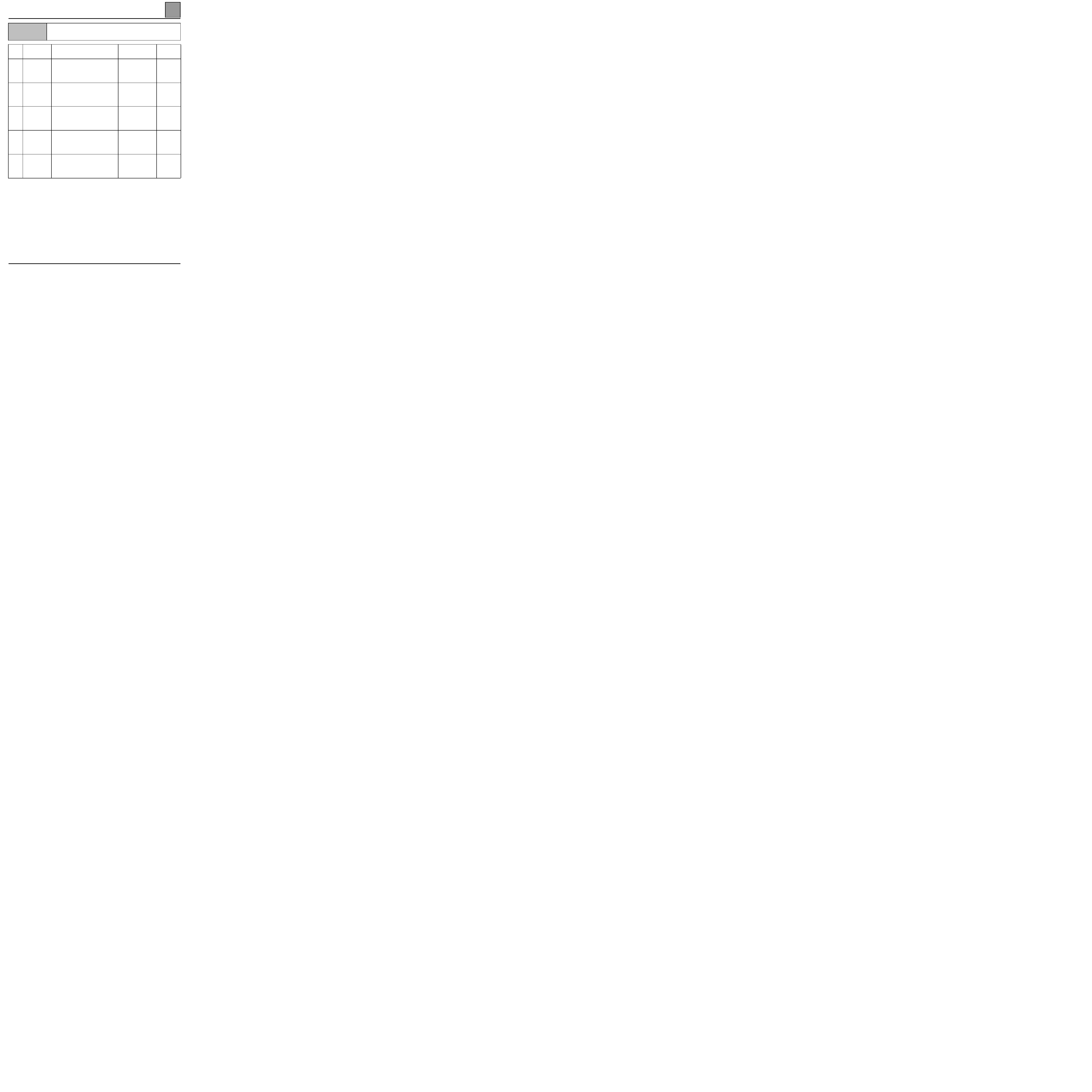
IMMOBILISER
Fault finding - Conformity check
82
Fault finding - Conformity check
NOTES
Only check the conformity after a full check using the fault finding tool.
Order
Function
Parameter / Condition checked or action
Viewing
and Notes
Fault
finding
1
Instrument
panel warning
light
ET001
+ 12 V accessories
ET060
Immobiliser
ET167
Immobiliser warning light
ACTIVE
ACTIVE
ACTIVE
2
Instrument
panel warning
light
ET002
+ 12 V after ignition
ET060
Immobiliser
ET167
Immobiliser warning light
ACTIVE
Inactive
Inactive
3 Different
states
ET103
Key code received
ET104
Key code valid
YES
YES
DF032
DF030
DF031
4
Forced
protection
mode
ET127
Forced protection mode
ACTIVE following
command
5
Diesel EV
discharge
Only on G8T engine
Solenoid valve
knocking
DF053
82-7

IMMOBILISER
Fault finding - Customer complaints
82
Fault finding - Customer complaints
NOTES
Only consult the customer complaints after a complete check using the diagnostic tool
ABSENCE OF DIALOGUE WITH THE PASSENGER COMPARTMENT CONNECTION UNIT
CHART 1
IGNITION ON, IMMOBILISER WARNING LIGHT FLASHES PERMANENTLY
(impossible to start)
CHART 2
IMMOBILISER WARNING LIGHT REMAINS PERMANENTLY ILLUMINATED (even when
ignition turned off) OR REMAINS PERMANENTLY EXTINGUISHED
CHART 3
IGNITION ON, INJECTION WARNING LIGHT FLASHES PERMANENTLY (impossible to start)
CHART 4
WHEN DRIVING (deceleration) OR IDLING, THE INJECTION WARNING LIGHT FLASHES
PERMANENTLY
CHART 5
THE VEHICLE WILL NOT START
CHART 6
IGNITION ON, IMMOBILISER WARNING LIGHT FLASHES PERMANENTLY
(impossible to start)
CHART 7
IMMOBILISER WARNING LIGHT REMAINS ILLUMINATED FOR LONGER THAN
30 CONSECUTIVE SECONDS, IGNITION ON (the immobiliser warning light illuminates when
ignition turned on, in the 16 seconds following turning on the ignition or the immobiliser
warning light illuminates for longer than 30 consecutive seconds)
CHART 8
WHEN THE IGNITION IS TURNED ON, THE IMMOBILISER ILLUMINATES FOR 3 SECONDS,
THEN EXTINGUISHES, BUT THE VEHICLE WILL NOT START
CHART 9
IMMOBILISER WARNING LIGHT REMAINS PERMANENTLY ILLUMINATED (even when
ignition turned off) OR REMAINS PERMANENTLY EXTINGUISHED
CHART 10
THE VEHICLE WILL NOT START
CHART 11
82-8
IMMOBILISER
Fault finding - Fault charts
82
Fault finding - Fault charts
CHART 1
ABSENCE OF DIALOGUE WITH THE PASSENGER COMPARTMENT
CONNECTION UNIT
NOTES
Bornier ELE. 1506
Check the condition of + before igntion fuses.
Change the fuse if necessary.
Ensure that the fault finding tool is not the cause of the fault by trying to communicate with another computer on
the vehicle (airbag computer, injection computer...).
Check the battery voltage (U > 10.5 volts).
Recharge the battery if necessary.
Check that the passenger compartment connection unit BII yellow 26 track connector (A) is properly locked.
Check that the passenger compartment connection unit BII is supplied correctly:
– earth in track 1 of the passenger compartment connection unit BII white connector (C).
– + before ignition in track 13 of the passenger compartment connection unit BII yellow 26 track connector (A).
Ensure that the diagnostic socket is correctly fed.
Check and ensure the continuity and insulation of the electrical wiring of tracks 2 and 15 of the passenger
compartment connection unit BII yellow 26 track connector (A).
If there is still no dialogue between the fault finding tool and the passenger compartment connection unit BII,
change the passenger compartment connection unit BII.
See passenger compartment connection unit BII configuration.
AFTER REPAIR
When communication is established, deal with any faults indicated.
82-9
IMMOBILISER
Fault finding - Fault charts
82
82-10
CHART 2
IGNITION ON, IMMOBILISER WARNING LIGHT FLASHES
PERMANENTLY (impossible to start)
NOTES
Only consult this customer complaint after a complete check using the fault finding tool
Switch on and check the presence of + after ignition feed and + ACC.
Switch the ignition off and wait for the immobiliser warning light to flash (immobiliser active).
Switch on again and check DF031.
Check the key recognition function.
Try to start the vehicle with the second key.
Check the condition of the antenna ring.
Check the continuity and insulation against earth and against 12 volts of the electrical wiring between:
connector (B)
JA 26 tracks connection unit and the antenna ring
passenger compartment
connection unit BII
8
4
22
3
21
6 (earth)
9
1
antenna
ring
Switch the ignition off and wait for the immobiliser warning light to flash (immobiliser active).
Disconnect the antenna ring connector.
Place the fault finding tool in pulse sensor.
When switching the ignition on again, check for an impulse on track 9 of the passenger compartment connection
unit 26 track (B) connector (test with the connection unit connectors connected).
If there are no impulses, change the passenger compartment connection unit (BII).
Switch the ignition off and wait for the immobiliser warning light to flash (immobiliser active).
Switch on again and check ET060. If ET060 is active, change the antenna ring.
If the fault persists, change the key.
AFTER REPAIR
Carry out a check using the fault finding tool.
Deal with any faults found.
IMMOBILISER
Fault finding - Fault charts
82
82-11
CHART 3
IMMOBILISER WARNING LIGHT REMAINS PERMANENTLY ILLUMINATED (even
when ignition turned off ) OR REMAINS PERMANENTLY EXTINGUISHED
NOTES
Only consult this customer complaint after a complete check using the fault finding tool
Check the condition of +before ignition feed fuse.
Check the engine configuration.
Replace the immobiliser warning light.
AFTER REPAIR
Carry out a check using the fault finding tool.
Deal with any faults found.

IMMOBILISER
Fault finding - Fault charts
82
82-12
CHART 4
IGNITION ON, INJECTION WARNING LIGHT FLASHES PERMANENTLY
(impossible to start)
NOTES
Only consult this customer complaint after a complete check using the fault finding tool
Check the continuity and insulation against earth and against 12 volts of the wiring between track 18 of the
connection unit 26 track blue connector (F) and the injection computer track.
With the ignition on, check that impulses are present on track 18 of the connection unit blue 26 track (F)
connector of the (test with the connection unit connectors and the injection computer connected).
If there are no impulses, change the passenger compartment connection unit (BII).
If there are impulses, change the injection computer.
AFTER REPAIR
Carry out a check using the fault finding tool.
Deal with any faults found.

IMMOBILISER
Fault finding - Fault charts
82
82-13
CHART 5
WHEN DRIVING (deceleration) OR IDLING, THE INJECTION WARNING LIGHT
FLASHES PERMANENTLY
NOTES
Only consult this customer complaint after a complete check using the fault finding tool
With the ignition on, check the presence of impulses on track 18 of the passenger compartment connection unit
blue 26 track connector (F).
If there is no impulse, change the passenger compartment connection unit BII.
If there are impulses, change the injection computer.
AFTER REPAIR
Carry out a check using the fault finding tool.
Deal with any faults found.
IMMOBILISER
Fault finding - Fault charts
82
82-14
CHART 6
THE VEHICLE WILL NOT START
NOTES
Only consult this customer complaint after a complete check using the fault finding tool
Check that ET001 and ET002 are active.
Check the airbag casing configuration (TECHNICAL NOTE 3149A).
– If the impact sensor is present when "fuel pump unauthorised".
– If the impact sensor is not present when "fuel pump authorised".
If the fault persists, there is an engine fault.
AFTER REPAIR
Carry out a check using the fault finding tool.
Deal with any faults found.
IMMOBILISER
Fault finding - Fault charts
82
82-15
CHART 7
IGNITION ON, IMMOBILISER WARNING LIGHT FLASHES PERMANENTLY
(impossible to start)
NOTES
G8T engine.
Switch the ignition on and check that ET002 is illuminated.
Switch the ignition off and wait for the immobiliser warning light to flash (immobiliser active).
Switch the ignition on and check that DF031 is activated.
Check the key recognition function. Try to start the vehicle with the second key.
If the vehicle starts, change the first key.
Check the condition of the antenna ring.
Check the continuity and insulation against earth and against 12 volts of the electrical wiring between:
connection unit 26 track
yellow connector (B)
8
4
22
3
21
6 (earth)
9
1
antenna ring
Switch the ignition off and wait for the immobiliser warning light to flash (immobiliser active). Disconnect the
antenna ring connector.
When switching the ignition on again, check for an impulse on track 9 of the passenger compartment connection
unit yellow 26 track (B) connector (test with the connection unit connectors connected).
If there are no impulses, change the passenger compartment connection unit (BII).
Switch the ignition off and wait for the immobiliser warning light to flash (immobiliser active).
Switch the ignition on again and check that ET060 is active.
If it is active, change the antenna ring.
AFTER REPAIR
Carry out a check using the fault finding tool.
Deal with any faults found.

IMMOBILISER
Fault finding - Fault charts
82
82-16
CHART 8
IMMOBILISER WARNING LIGHT REMAINS ILLUMINATED FOR LONGER THAN
30 CONSECUTIVE SECONDS, IGNITION ON (the immobiliser warning light
illuminates when ignition turned on, in the 16 seconds following turning on the
ignition or the immobiliser warning light illuminates for longer than
30 consecutive seconds)
NOTES
G8T engine
Check the condition of the electric wiring between:
Solenoid valve coded
electronic unit
connector
1
2
3
18 of the connection unit 26 track connector (F)
+ after ignition fuse (see impact switch)
vehicle earth
With the ignition on, check that impulses are present on track 18 of the connection unit 26 track (F) connector
(test with the connection unit and the solenoid valve coded electronic unit connectors connected).
If there are no impulses, change the passenger compartment connection unit (BII).
Carry out a mechanical check of the solenoid valve:
– Ignition off, control "AC060".
– Switch on the ignition again. The valve should open and close several times in 30 seconds (listen).
Replace the solenoid valve coded electronic unit.
AFTER REPAIR
Carry out a check using the fault finding tool.
Deal with any faults found.

IMMOBILISER
Fault finding - Fault charts
82
82-17
CHART 9
WHEN THE IGNITION IS TURNED ON, THE IMMOBILISER ILLUMINATES FOR 3
SECONDS, THEN EXTINGUISHES, BUT THE VEHICLE WILL NOT START
NOTES
G8T engine
Carry out a mechanical check of the solenoid valve:
– Ignition off, control "AC060".
– Switch on the ignition again. The valve should open and close several times in 30 seconds (listen).
Solenoid valve coded electronic unit is not faulty. Refer to fault finding for the diesel engine.
Remove the solenoid valve coded electronic unit.
Check the condition of the solenoid valve.
If the fault persists, change the solenoid valve coded electronic unit.
AFTER REPAIR
Carry out a check using the fault finding tool.
Deal with any faults found.

IMMOBILISER
Fault finding - Fault charts
82
82-18
CHART 10
IMMOBILISER WARNING LIGHT REMAINS PERMANENTLY ILLUMINATED
(even when ignition turned off ) OR REMAINS PERMANENTLY EXTINGUISHED
NOTES
G8T engine
Check the engine configuration.
Replace the immobiliser warning light.
AFTER REPAIR
Carry out a check using the fault finding tool.
Deal with any faults found.

IMMOBILISER
Fault finding - Fault charts
82
82-19
CHART 11
THE VEHICLE WILL NOT START
NOTES
G8T engine
Check ET001 and ET002.
Check the airbag casing configuration (TECHNICAL NOTE 3149A). See page 84-26
If the problem persists, there is a problem with the engine or with the coded solenoid valve.
AFTER REPAIR
Carry out a check using the fault finding tool.
Deal with any faults found.

INSTRUMENT PANEL
Fault finding - Introduction
83
183
INSTRUMENT PANEL
Fault finding - Introduction
GENERAL APPROACH TO FAULT FINDING:
– Use of one of the fault finding tools to identify the system equipping the vehicle (to read the computer
family, the program number, the vdiag, etc.).
– Finding the "Fault finding" documents corresponding to the system identified.
– Inclusion of information contained in the introductory sections.
– Reading the faults stored in the computer memory and using the "Interpretation of faults" section of the
documents.
Reminder: Each fault is interpreted for a particular type of storage (fault present, fault stored, fault present
or stored). The checks defined for handling each fault are therefore only to be performed if the fault stated
by the fault finding tool is interpreted in the document for its type of storage. The storage type should be
considered when using fault finding tool following ignition switch-off and switch-on.
If a fault is interpreted when it is stated to be "stored", the conditions for application of the fault finding
appear in the "NOTES" box. When the conditions are not satisfied, use the fault finding to check the circuit
of the faulty part since the fault is no longer present on the vehicle. Perform the same operation when a
fault is stated as "stored" by the fault finding tool but is only interpreted in the documentation for a
"present" fault.
– Perform the conformity check (appearance of possible incorrect operations not yet stated by the system's
self diagnosis procedure) and apply the associated fault finding strategy according to results.
– Validation of the repair (disappearance of the phenomenon reported by the customer).
– Use of the fault finding strategy for each "Customer complaint" if the problem persists.
This document introduces the generic fault finding strategy applicable to all "Instrument panel" (relevant
section: Bii-J66, software version 0370; 0380; 0390; 0400).
A Technical Note "Fault Finding Special Features" is available for each vehicle fitted with this computer /
this function. It covers all the fault finding special features in this document for the vehicle concerned.
This "Special Features" Note completes and cancels the information provided in the "Generic" fault
finding Note.
The following are thus required to carry out fault finding on this system:
– The "Generic Fault Finding" Technical Note,
– The "Fault Finding Special Features" Technical Note for the vehicle,
– The wiring diagram for operation of the vehicle concerned,
– The tools listed in the "special tooling required" list.
83-1
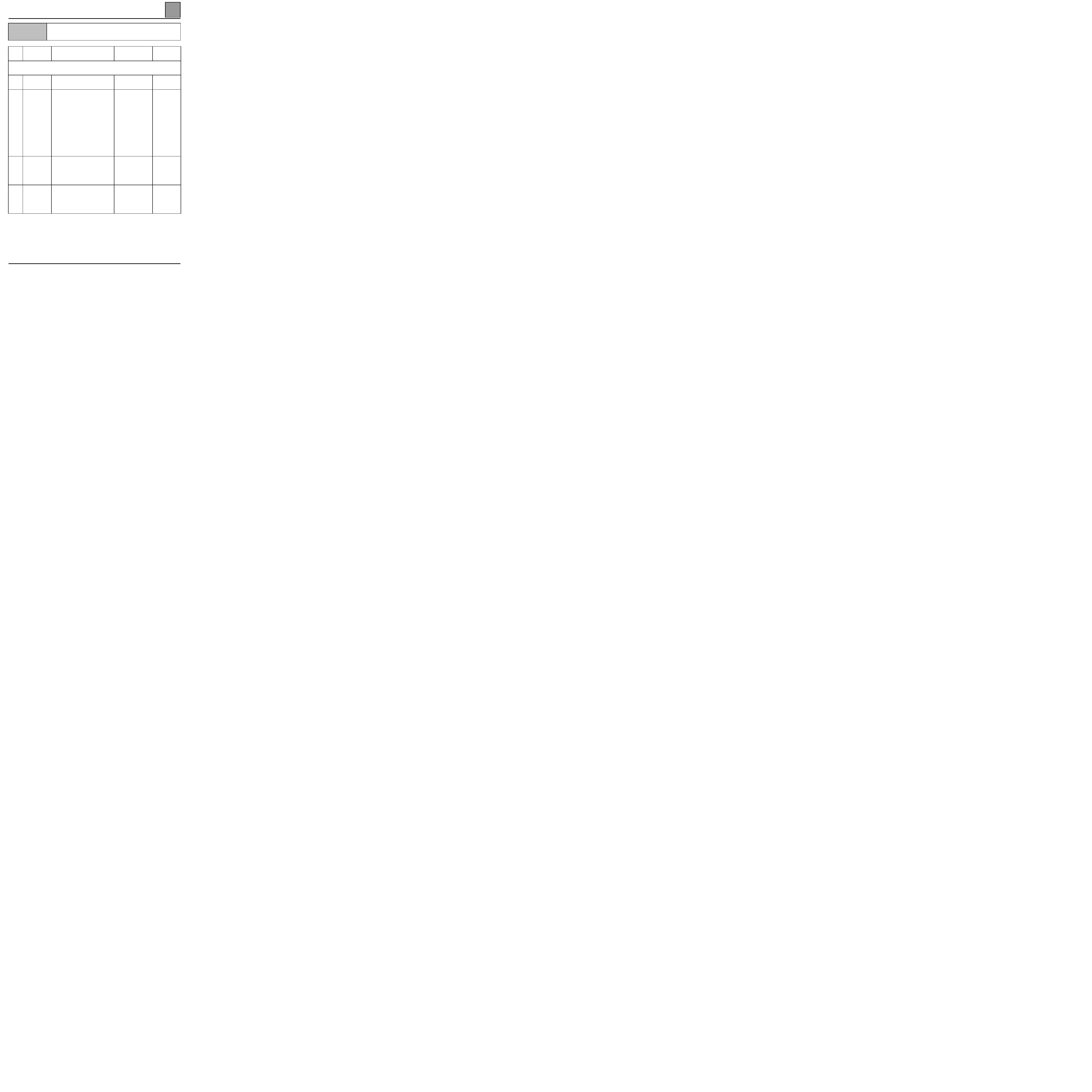
INSTRUMENT PANEL
Fault finding - Conformity check
83
Fault finding - Conformity check
NOTES
Only check the conformity after a full check using the fault finding tool.
Order
Function
Parameter / Condition checked or
action
Viewing
and Notes
Fault finding
Status Window
1 Battery
voltage
ET002
+ 12 V after ignition
ACTIVE
2 Configuration
LC037
LC043
LC036
LC035
LC046
LC040
LC038
Engine type: L7X, F3R, Z7X,
F3R GPL, G8T VP20, G8T,
G9T, F9Q, F4R
Type of driving style: right,
left
BII type: B1, B2, B3
Cluster type: E1, E2, E3.
Airbag type: EC5, SDM
Controlled heating and
ventilation system: yes, no
Pressure switch: old, new
Configuration reading
See p 87-04
for the
configuration
3
Instrument
panel BII link
DF080
Instrument panel BII link
Fault not present
In the event of
a problem,
consult the
relevant fault
finding
4
Radio
frequency
remote control
reception
ET113
ET010
IR/RF network received
RF key valid
YES (if radio
frequency remote
control is correct size)
YES (if correct code)
83-2

PASSENGER COMPARTMENT CONNECTION UNIT
Fault finding - Introduction
87
187
PASSENGER COMPARTMENT CONNECTION UNIT
Fault finding - Introduction
GENERAL APPROACH TO FAULT FINDING:
– Use of one of the fault finding tools to identify the system equipping the vehicle (to read the computer
family, the program number, the vdiag, etc.).
– Finding the "Fault finding" documents corresponding to the system identified.
– Inclusion of information contained in the introductory sections.
– Reading the faults stored in the computer memory and using the "Interpretation of faults" section of the
documents.
Reminder: Each fault is interpreted for a particular type of storage (fault present, fault stored, fault present
or stored). The checks defined for handling each fault are therefore only to be performed if the fault stated
by the fault finding tool is interpreted in the document for its type of storage. The storage type should be
considered when using fault finding tool following ignition switch-off and switch-on.
If a fault is interpreted when it is stated to be "stored", the conditions for application of the fault finding
appear in the "NOTES" box. When the conditions are not satisfied, use the fault finding to check the circuit
of the faulty part since the fault is no longer present on the vehicle. Perform the same operation when a
fault is stated as "stored" by the fault finding tool but is only interpreted in the documentation for a
"present" fault.
– Perform the conformity check (appearance of possible incorrect operations not yet stated by the system's
self diagnosis procedure) and apply the associated fault finding strategy according to results.
– Validation of the repair (disappearance of the phenomenon reported by the customer).
– Use of the fault finding strategy for each "Customer complaint" if the problem persists.
This document introduces the generic fault finding strategy applicable to all "Passenger compartment
connection unit" (relevant section: Bii-J66, software version 0370; 0380; 0390; 0400).
A Technical Note "Fault Finding Special Features" is available for each vehicle fitted with this computer
/ this function. It covers all the fault finding special features in this document for the vehicle concerned.
This "Special Features" Note completes and cancels the information provided in the "Generic" fault
finding Note.
The following are thus required to carry out fault finding on this system:
– The "Generic Fault Finding" Technical Note,
– The "Fault Finding Special Features" Technical Note for the vehicle,
– The wiring diagram for operation of the vehicle concerned,
– The tools listed in the "special tooling required" list.
87-1

PASSENGER COMPARTMENT CONNECTION UNIT
Diagnostics - Fault Interpretation
87
Diagnostics - Fault Interpretation
DF033
Tailgate circuit
CC.1
:
Short circuit to + 12 volts
CC.0
:
Short circuit to earth or open circuit
NOTES
None
CC.1
NOTES
None
Check the insulation at + 12 volts of the (BUS) line between track 4 of the passenger compartment connection
unit (BII) yellow 26 track connector (A) and track 3 of the tailgate module of the 4 track connector.
Rectify the (BUS) line, if necessary.
CC.0
NOTES
None
Check the continuity and insulation against earth between track 4 of the passenger compartment connection unit
(BII) yellow 26 track connector (A) and track 3 of the tailgate module of the 4 track connector.
Is there continuity?
YES
Change the tailgate module.
NO
Replace the (BUS) line between track 4 of the passenger compartment connection unit (BII)
yellow 26 track connector (A) and track 3 of the tailgate module of the 4 track connector.
AFTER REPAIR
Clear the computer memory.
Carry out a check using the fault finding tool.
Deal with any faults found.
87-2

PASSENGER COMPARTMENT CONNECTION UNIT
Diagnostics - Fault Interpretation
87
87-3
DF 046
PRESENT
OR
MEMORISED
Battery charge
NOTES
If DF050 DF055 DF060 DF091 are also stored in memory, deal too with CAS 1.
Use bornier Elé 1506 for the measures.
Check the insulation of the line in track 12 and the blue 26 track connector (F) earth.
Repair if necessary.
CAS1
NOTES
None
Check the continuity between the connections:
track 13
track 5
track 26
track 6
If the fault persists and the instrument panel warning lights are not active, change the instrument panel.
Check the illumination of the warning lights using a fault finding tool.
If the fault persists and only some warning lights are inactive or there is an incorrect display, change the
passenger compartment connection unit.
AFTER REPAIR
Clear the computer memory.
Carry out a check using the fault finding tool.
Deal with any faults found.

PASSENGER COMPARTMENT CONNECTION UNIT
Diagnostics - Fault Interpretation
87
87-4
DF 047
PRESENT
OR
MEMORISED
Minimum oil level
NOTES
Use bornier Elé 1506 for the measures.
Check the level using a dipstick.
Measure the probe resistance value between tracks 3 and 16 of the passenger compartment connection unit
26 track blue connector F: 7 Ω < R < 15 Ω.
Replace the probe if the value is not correct.
AFTER REPAIR
Clear the computer memory.
Carry out a check using the fault finding tool.
Deal with any faults found.

PASSENGER COMPARTMENT CONNECTION UNIT
Diagnostics - Fault Interpretation
87
87-5
DF048
PRESENT
OR
MEMORISED
LPG gauge
CO : Open circuit
NOTES
None
CO
NOTES
None
Check the continuity between:
LPG gauge track B
Track 15 of the passenger compartment connection
unit 26 track Mot. blue connector
Check the continuity between:
LPG gauge track A
Track 4 of the passenger compartment connection
unit 12 track SS2 blue connector
If the fault persists, replace the LPG gauge.
AFTER REPAIR
Clear the computer memory.
Carry out a check using the fault finding tool.
Deal with any faults found.

PASSENGER COMPARTMENT CONNECTION UNIT
Diagnostics - Fault Interpretation
87
87-6
DF 050
PRESENT
OR
MEMORISED
Fuel gauge
CO
: Open circuit
NOTES
If DF050 DF055 DF060 DF091 are also stored in memory, deal too with CAS 1.
Use bornier Elé 1506 for the measures.
CO
NOTES
None
Check the continuity of the line by measuring between tracks 15 and 2 of the passenger compartment
connection unit (BII) blue 26 track connector (F).
Repair if necessary.
If the fault persists, replace the fuel gauge.
CAS1
NOTES
None
Check the continuity between the connections:
track 13
track 5
track 26
track 6
If the fault persists and the instrument panel warning lights are not active, change the instrument panel.
Check the illumination of the warning lights using a fault finding tool.
If the fault persists and only some warning lights are inactive or there is an incorrect display, change the
passenger compartment connection unit.
AFTER REPAIR
Clear the computer memory.
Carry out a check using the fault finding tool.
Deal with any faults found.

PASSENGER COMPARTMENT CONNECTION UNIT
Diagnostics - Fault Interpretation
87
87-7
DF052
PRESENT
OR
MEMORISED
External temperature sensor circuit
CC
: Short circuit
NOTES
Use bornier Elé 1506 for the measures.
CC
NOTES
None
Check the insulation between tracks 16 and 3 on the passenger compartment connection unit (BII) yellow
26 track connector (A).
Repair if necessary.
If the fault persists, replace the external temperature sensor.
AFTER REPAIR
Clear the computer memory.
Carry out a check using the fault finding tool.
Deal with any faults found.

PASSENGER COMPARTMENT CONNECTION UNIT
Diagnostics - Fault Interpretation
87
87-8
DF054
PRESENT
OR
MEMORISED
Minimum oil pressure
CC.0 : Short circuit to earth
NOTES
If illuminated, check the rating circuit.
CC.0
NOTES
Use bornier Elé 1506 for the measures.
Check the insulation against earth of the line in track 22 of the passenger compartment connection unit blue
26 track connector (F).
Repair if necessary.
If the fault persists, replace the oil pressure sensor.
AFTER REPAIR
Clear the computer memory.
Carry out a check using the fault finding tool.
Deal with any faults found.
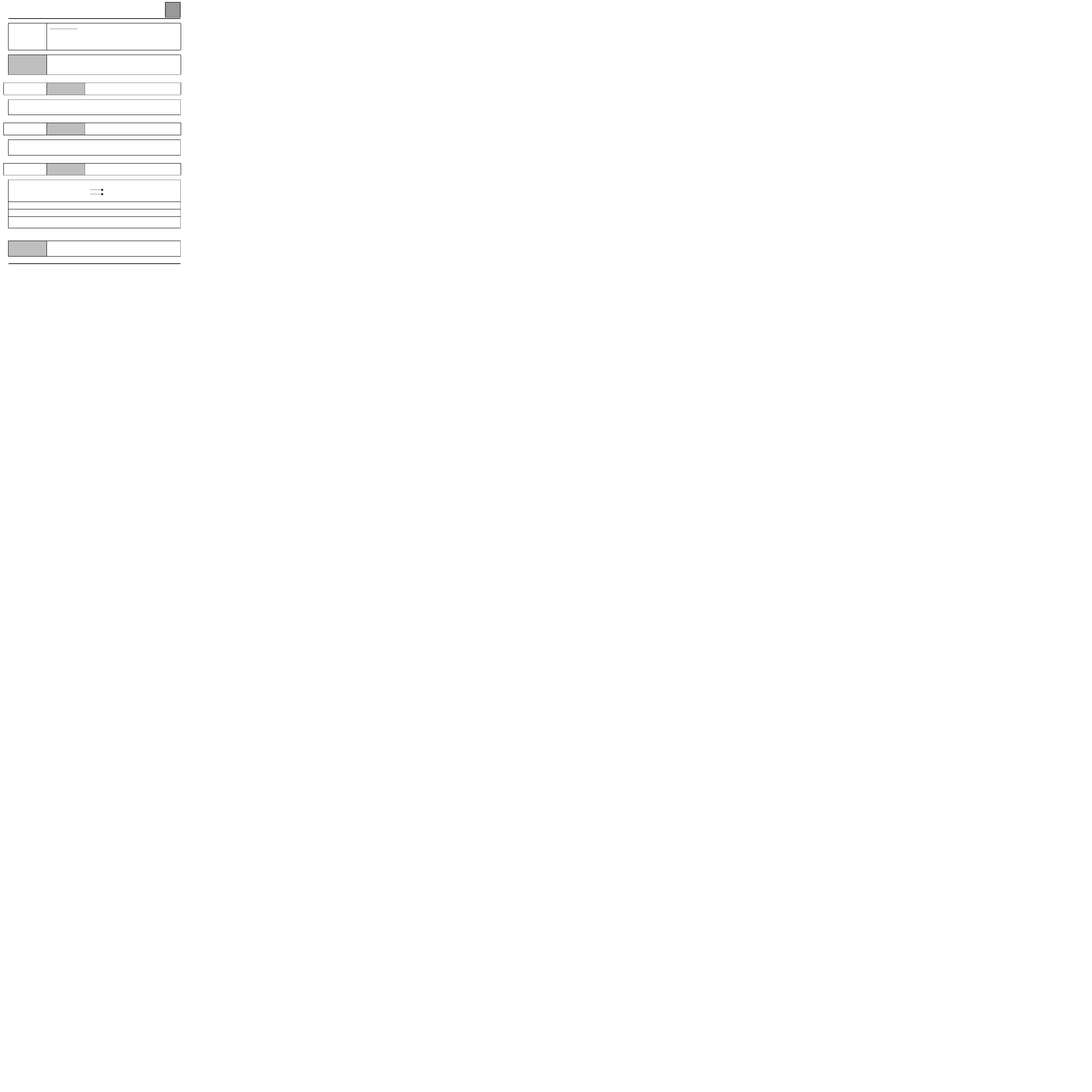
PASSENGER COMPARTMENT CONNECTION UNIT
Diagnostics - Fault Interpretation
87
87-9
DF055
PRESENT
OR
MEMORISED
Oil level sensor
CO
: Open circuit
CC
: Short circuit
NOTES
Important timed control.
On request instrument panel display (if parametered).
If DF050 DF055 DF060 DF091 are also stored in memory, then deal with CAS 1.
CO
NOTES
Use bornier Elé 1506 for the measures.
Disconnect the passenger compartment connection unit blue 26 track connector (F). Check the probe resistance
value between tracks 3 and 16, it should be between 10 and 15 ohms.
Replace the probe if the resistance value is not correct.
CC
NOTES
Use bornier Elé 1506 for the measures.
Check the insulation against earth and against + 12 volts between tracks 3 and 16 of the passenger
compartment connection unit blue 26 track connector (F).
Repair if necessary.
CAS1
NOTES
Use bornier Elé 1506 for the measures.
Check the continuity between the connections:
track 13
track 5
track 26
track 6
If the fault persists and the instrument panel warning lights are not active, change the instrument panel.
Check the illumination of the warning lights using a fault finding tool.
If the fault persists and only some warning lights are inactive or there is an incorrect display, change the
passenger compartment connection unit.
AFTER REPAIR
Clear the computer memory.
Carry out a check using the fault finding tool.
Deal with any faults found.

PASSENGER COMPARTMENT CONNECTION UNIT
Diagnostics - Fault Interpretation
87
87-10
DF058
PRESENT
OR
MEMORISED
Controlled heating and ventilation system line
CC.1 : Open circuit or short circuit to + 12 volts
CC.0 : Short circuit to earth
NOTES
Use bornier Elé 1506 for the measures.
Vehicle fitted with controlled heating and ventilation system.
CC.1
NOTES
None
Check the continuity or insulation at + 12 volts of the connection between:
26 track ECH yellow
passenger compartment
connection unit
track 16
track B9
of the air conditioning computer
Repair if necessary.
If the fault persists, replace the passenger compartment connection unit.
CC.0
NOTES
None
Check the insulation against earth of the connection between:
26 track ECH yellow
passenger compartment
connection unit
track 16
track B9
of the air conditioning computer
Repair if necessary.
If the fault persists, replace the passenger compartment connection unit.
AFTER REPAIR
Clear the computer memory.
Carry out a check using the fault finding tool.
Deal with any faults found.

PASSENGER COMPARTMENT CONNECTION UNIT
Diagnostics - Fault Interpretation
87
87-11
DF060
PRESENT
OR
MEMORISED
Fuel guage locking
NOTES
If DF050 DF055 DF060 DF091 are also stored in memory, deal too with CAS 1.
Use bornier Elé 1506 for the measures.
Remove the fuel gauge and check that it is operating.
Repair if necessary.
CAS1
NOTES
Use bornier Elé 1506 for the measures.
Check the continuity between the connections:
track 13
track 5
track 26
track 6
If the fault persists and the instrument panel warning lights are not active, change the instrument panel.
Check the illumination of the warning lights using a fault finding tool.
If the fault persists and only some warning lights are inactive or there is an incorrect display, change the
passenger compartment connection unit.
AFTER REPAIR
Clear the computer memory.
Carry out a check using the fault finding tool.
Deal with any faults found.

PASSENGER COMPARTMENT CONNECTION UNIT
Diagnostics - Fault Interpretation
87
87-12
DF080
PRESENT
OR
MEMORISED
BII connection instrument panel
NOTES
Use bornier Elé 1506 for the measures.
Check the continuity between the connections:
ECH 26 track yellow
passenger compartment
connection unit
track 13
track 5
track 26
track 6
Instrument panel 12 track
connector
If the fault persists and the instrument panel warning lights are not active, change the instrument panel.
Check the illumination of the warning lights using a fault finding tool.
If the fault persists and only some warning lights are inactive or there is an incorrect display, change the passenger
compartment connection unit.
AFTER REPAIR
Proceed with the configuration of a new component.

PASSENGER COMPARTMENT CONNECTION UNIT
Diagnostics - Fault Interpretation
87
87-13
DF085
PRESENT
OR
MEMORISED
Coolant temperature sensor circuit
CC
: Short circuit
1.DEF : Fan assembly or coolant temperature sensor failure
NOTES
Use bornier Elé 1506 for the measures.
CC
NOTES
None
Check the insulation against earth and against + 12 volts between track 26 and track 1 of the passenger
compartment connection unit blue 26 track connector (F).
Repair if necessary.
If the fault persists, replace the coolant temperature sensor.
1.DEF
NOTES
None
Check the fan assembly fuses in the engine compartment connection unit.
Check the fan assembly triggering temperature.
Repair if necessary.
AFTER REPAIR
Clear the computer memory.
Carry out a check using the fault finding tool.
Deal with any faults found.
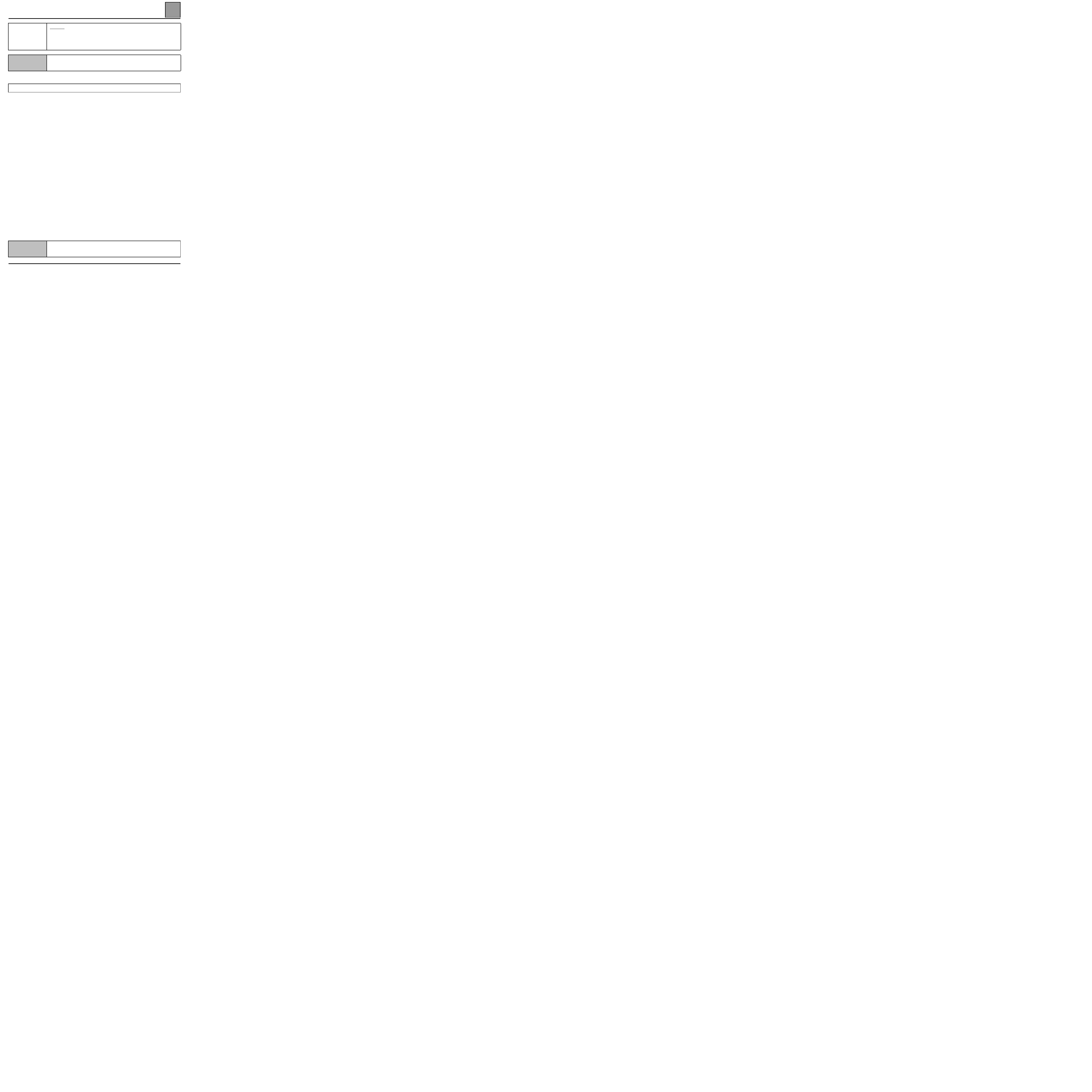
PASSENGER COMPARTMENT CONNECTION UNIT
Diagnostics - Fault Interpretation
87
87-14
DF088
PRESENT
OR
MEMORISED
Tailgate
NOTES
Use bornier Elé 1506 for the measures.
Replace the tailgate module.
AFTER REPAIR
Clear the computer memory.
Carry out a check using the fault finding tool.
Deal with any faults found.

PASSENGER COMPARTMENT CONNECTION UNIT
Diagnostics - Fault Interpretation
87
87-15
DF091
PRESENT
OR
MEMORISED
Worn front brake pads
NOTES
If DF050 DF055 DF060 DF091 are also stored in memory, deal too with CAS 1.
Use bornier Elé 1506 for the measures.
Check the insulation against earth of track 9 of the passenger compartment connection unit 26 track blue MOT
connector.
Check the brake pad wear.
CAS1
NOTES
Use bornier Elé 1506 for the measures.
Check the continuity between the connections:
track 13
track 5
track 26
track 6
If the fault persists and the instrument panel warning lights are not active, change the instrument panel.
Check the illumination of the warning lights using a fault finding tool.
If the fault persists and only some warning lights are inactive or there is an incorrect display, change the
passenger compartment connection unit.
AFTER REPAIR
Clear the computer memory.
Carry out a check using the fault finding tool.
Deal with any faults found.

PASSENGER COMPARTMENT CONNECTION UNIT
Diagnostics - Fault Interpretation
87
87-16
DF092
PRESENT
OR
MEMORISED
Bii connection
Automatic transmission
CC.0
: Short circuit to earth
NOTES
Use bornier Elé 1506 for the measures.
Vehicle fitted with automatic transmission.
CC.0
NOTES
None
Check the insulation against earth of the connection between:
Passenger compartment
connection unit SS2 12 track
blue connector
track 1
track 3
selector cluster automatic
transmission
Repair if necessary.
AFTER REPAIR
Clear the computer memory.
Carry out a check using the fault finding tool.
Deal with any faults found.

PASSENGER COMPARTMENT CONNECTION UNIT
Diagnostics - Fault Interpretation
87
87-17
DF093
PRESENT
OR
MEMORISED
Bii connection
ABS
CC.0 : Short circuit to earth
NOTES
Use bornier Elé 1506 for the measures.
CC.0
NOTES
None
Check the insulation against earth of the connection between:
Passenger compartment
connection unit MOT 26 track
blue connector
track 13
track 21
ABS computer connector
Repair if necessary.
AFTER REPAIR
Clear the computer memory.
Carry out a check using the fault finding tool.
Deal with any faults found.

PASSENGER COMPARTMENT CONNECTION UNIT
Diagnostics - Fault Interpretation
87
87-18
DF094
PRESENT
OR
MEMORISED
Bii connection
Attitude corrector
CC.0 : Short circuit to earth
NOTES
Use bornier Elé 1506 for the measures.
Vehicle fitted with attitude corrector.
CC.0
NOTES
None
Check the insulation against earth of the connection between:
Passenger compartment
connection unit SS2 12 track
blue connector
track 7
track 2
attitude corrector compressor unit
white connector
Repair if necessary.
AFTER REPAIR
Clear the computer memory.
Carry out a check using the fault finding tool.
Deal with any faults found.

PASSENGER COMPARTMENT CONNECTION UNIT
Diagnostics - Fault Interpretation
87
87-19
DF095
PRESENT
OR
MEMORISED
Bii connection
Injection
CC.0 : Short circuit to earth
NOTES
Use bornier Elé 1506 for the measures.
CC.0
NOTES
None
Check the insulation against earth of the connection between:
passenger compartment
connection unit MOT 26
track blue connector
track 21
track 27
track 26
track 1-G3
track 15
track 34
G8T VP20 injection computer connector
F9Q, F3R injection computer connector
G9T injection computer connector
L7X injection computer connector
F4R injection computer connector
Repair if necessary.
AFTER REPAIR
Clear the computer memory.
Carry out a check using the fault finding tool.
Deal with any faults found.

PASSENGER COMPARTMENT CONNECTION UNIT
Diagnostics - Fault Interpretation
87
87-20
DF097
PRESENT
OR
MEMORISED
Bii connection
Airbag / Pretentioners
CC.0 : Short circuit to earth
NOTES
Use bornier Elé 1506 for the measures.
CC.0
NOTES
None
Check the insulation against earth of the connection between:
passenger compartment
connection unit SS1 26 track
yellow connector
track 6
track 8
track 14
track 23
EC5 airbag computer
SDM airbag computer
Repair if necessary.
AFTER REPAIR
Clear the computer memory.
Carry out a check using the fault finding tool.
Deal with any faults found.
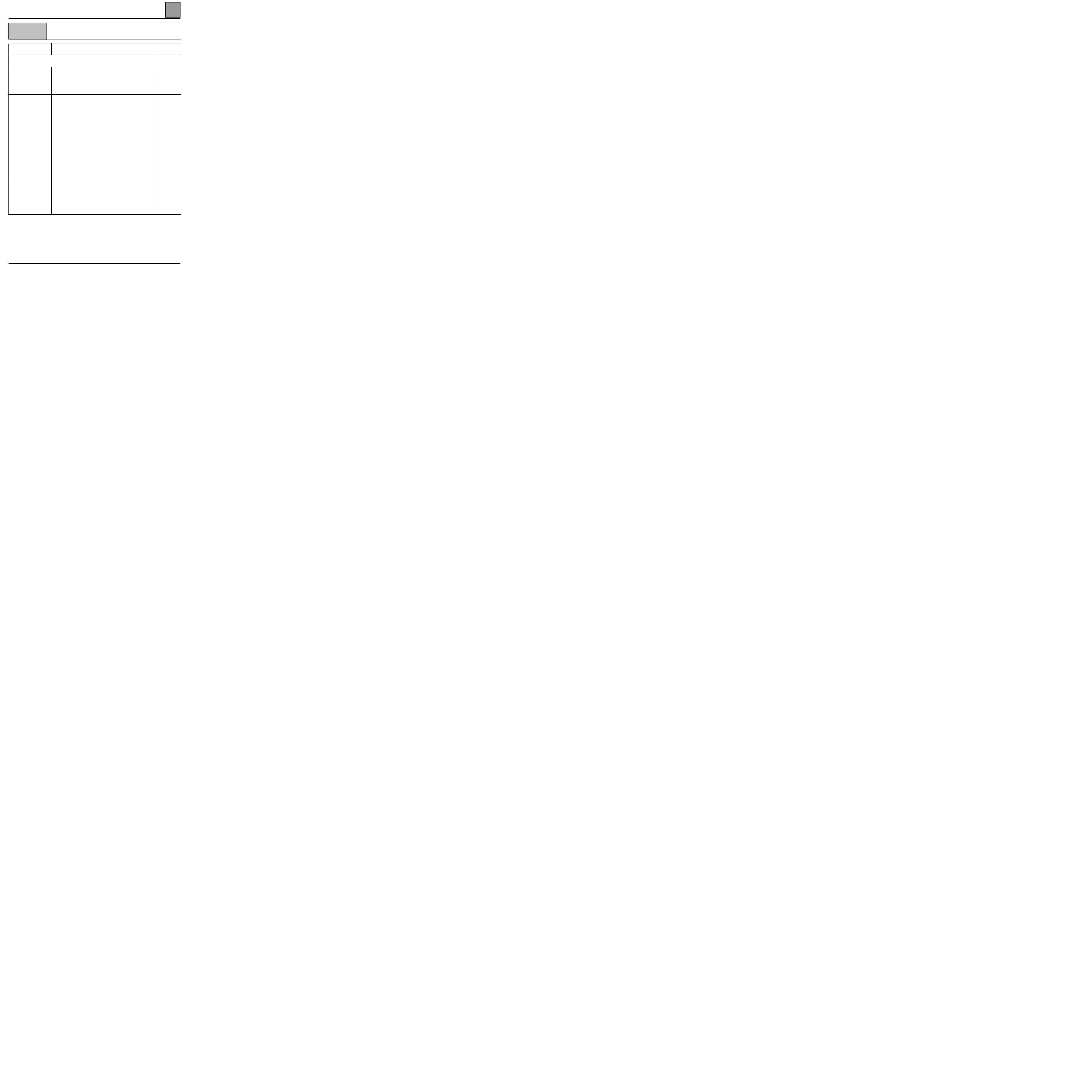
PASSENGER COMPARTMENT CONNECTION UNIT
Fault finding - Conformity check
87
Fault finding - Conformity check
NOTES
Only check the conformity after a full check using the fault finding tool.
Order
Function
Parameter / Condition checked or
action
Viewing
and Notes
Fault finding
Status Window
Configuration reading
1 Battery
voltage
ET001
ET002
+ 12 V accessories
+ 12 V after ignition
Status
Status
In the event of a
problem,
consult the fault
finding tool
ET001
ET002
2 Configuration
LC037
LC043
LC036
LC035
LC046
LC040
LC038
LC041
Engine type: L7X, F3R, Z7X,
F3R GPL, G8T VP20, G8T,
G9T, F9Q, F4R
Type of driving style: right-
hand, left-hand
BII type: B1, B2, B3
Cluster type: E1, E2, E3
Airbag type: EC5 (until 12/
1998), SDM (from 01/1999)
Controlled heating and
ventilation system: YES, NO
Pressure switch: old
Rear screen: fixed, opening
20 s oil level display: until
September 2000,
20 s oil level display on ADAC
support: from September 2000.
Configuration
reading
3
instrument
panel Bii
connection
Tailgate
module Bii
connection
Instrument panel Bii connection
Tailgate module Bii connection
Fault not present
In the event of a
problem,
consult
diagnostic
DF080
DF033
87-21
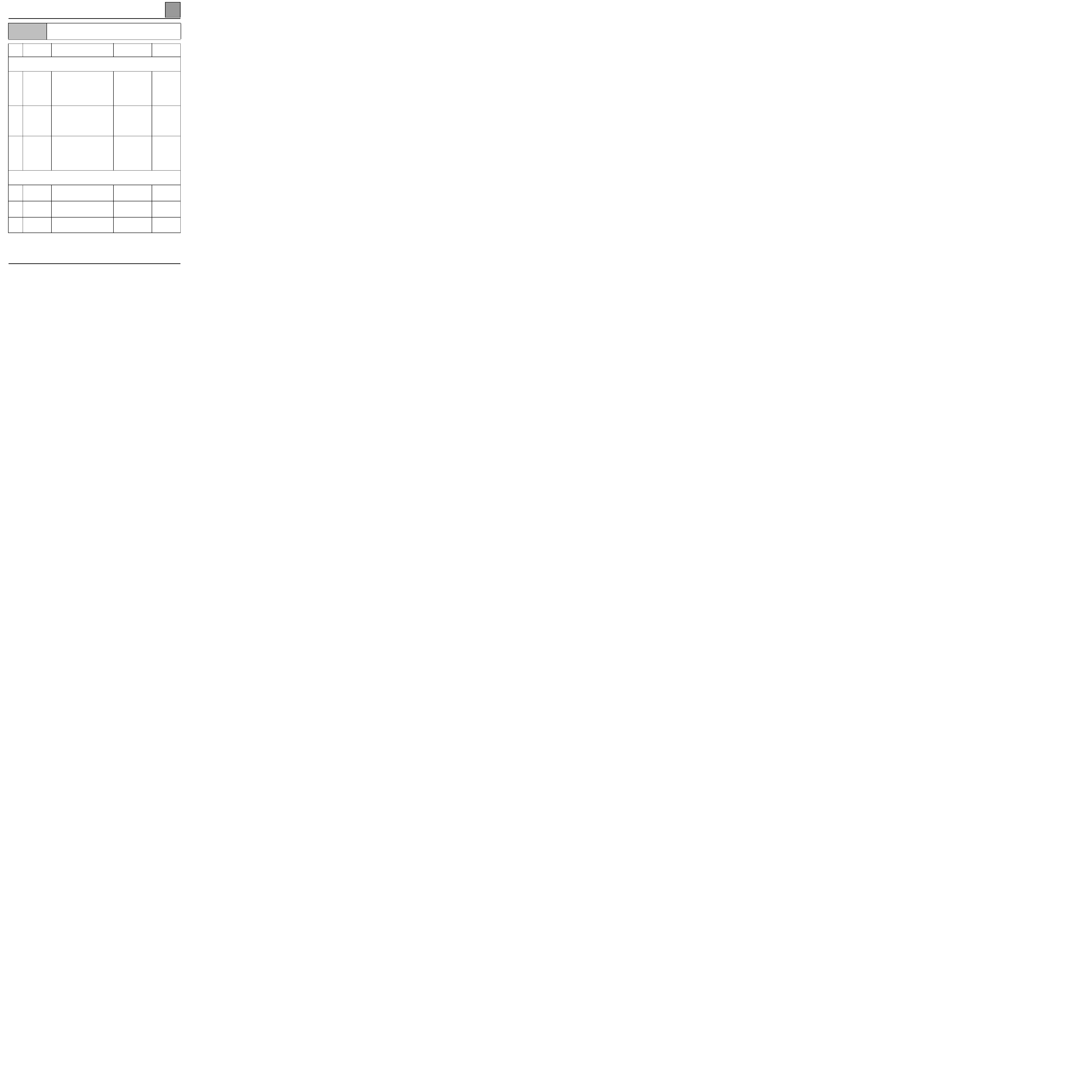
PASSENGER COMPARTMENT CONNECTION UNIT
Fault finding - Conformity check
87
87-22
NOTES
Only check the conformity after a full check using the fault finding tool.
Order
Function
Parameter / Condition checked or
action
Viewing
and Notes
Fault finding
Parameter Window
4
Coolant
temperature
PR059
ET087
Coolant temperature
X = 0 to 9
(number of barcharts
displayed on the
instrument panel)
In the event of a
problem,
consult
diagnostic
DF085
5 Fuel
level
PR057
ET118
Fuel level
X = 0 to 9
(number of barcharts
displayed on the
instrument panel)
In the event of a
problem,
consult
diagnostic
DF050
6 Oil
level
PR058
ET166
Oil level
X = 0 to 9
(number of barcharts
displayed on the
instrument panel)
In the event of a
problem,
consult
diagnostic
DF055
DF054
Command Window
7 LED
Software
AC066
Immobiliser warning
light illumination
Instrument panel LED
activated
8 Indicators
AC015
AC016
Right
Left
Illumination of the
indicators concerned
9 Courtesy
lights
AC053
AC054
Front courtesy lights
Rear courtesy lights
The 1
st
rail of lights
illuminates or the 2
nd
and 3
rd
rails
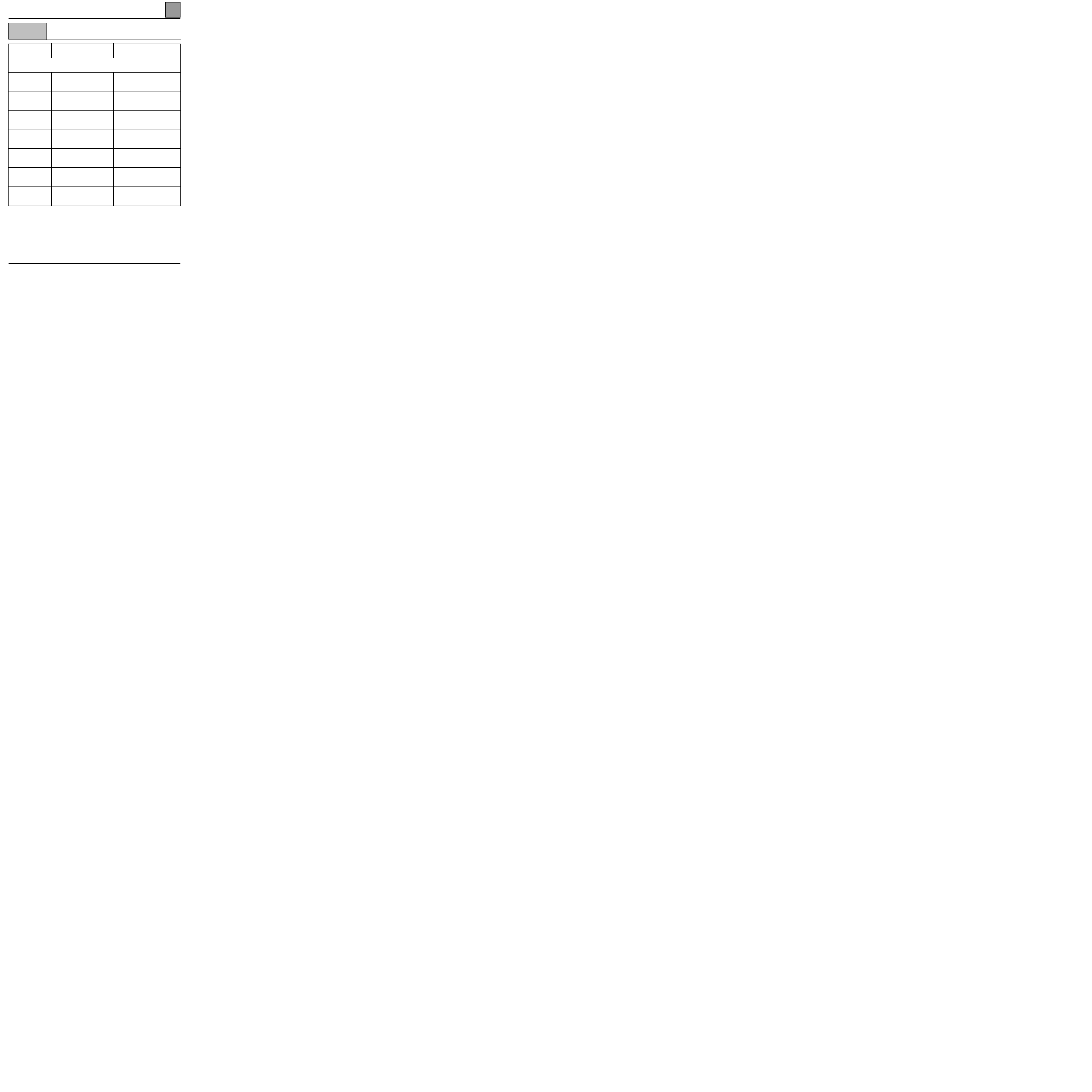
PASSENGER COMPARTMENT CONNECTION UNIT
Fault finding - Conformity check
87
87-23
NOTES
Only check the conformity after a full check using the fault finding tool.
Order
Function
Parameter / Condition checked or
action
Viewing
and Notes
Fault finding
Command Window (continued)
10
Windscreen
wiper
AC064
AC029
low speed
Rear screen wiper
Operation of
windscreen wiper
concerned
11 Fog
light
AC044
AC045
Front
Rear
Operation of fog light
concerned
12
Hazard warning
light
AC014
Hazard warning light
Illumination of all the
indicators
13
Headlight
washers
AC070
Headlight washers
The headlight
washers must operate
14
Driver's
window
AC024
AC025
Lowered
Raised
The driver's window
mustv operate
15
Opening
elements
AC063
AC072
Locking
Unlocking
All the opening
elements must lock
16 Stop
AC075
Actuator command end
Required command
for stopping any
activated functions

PASSENGER COMPARTMENT CONNECTION UNIT
Diagnostics - Status Interpretation
87
Diagnostics - Status Interpretation
ET001
+ 12 V Accessories
NOTES
Use bornier Elé 1506 for the measures.
Check the condition of + ACC fuse.
Change the fuse if necessary.
With the ignition on, check that a voltage of + 12 volts is present on track 5 of the passenger compartment
connection unit (Bii) yellow 26 track connector (A).
Are there 12 volts ?
YES
Change the passenger compartment connection unit (BII).
NO
Repair the electrical wiring between track 5 of the passenger compartment connection unit
BII yellow 26 track connector (A) and the passenger compartment fuse board.
AFTER REPAIR
Restart the conformity check from the beginning.
87-24

PASSENGER COMPARTMENT CONNECTION UNIT
Diagnostics - Status Interpretation
87
87-25
ET002
+ 12 V after ignition
NOTES
Use bornier Elé 1506 for the measures.
Check the condition of the + after ignition fuse.
Change the fuse if necessary.
With the ignition on, check that a voltage of + 12 volts is present on track 17 of the passenger compartment
connection unit (Bii) yellow 26 track connector (A).
Are there 12 volts ?
YES
Change the passenger compartment connection unit (BII).
NO
Repair the electrical wiring between track 17 of the passenger compartment connection unit
BII yellow 26 track connector (A) and the passenger compartment fuse board.
AFTER REPAIR
Restart the conformity check.

PASSENGER COMPARTMENT CONNECTION UNIT
Diagnostics - Status Interpretation
87
87-26
ET005
Windscreen wiper park position
NOTES
Illuminated when the switch is in park position.
Check the connection between track 25 of the passenger compartment connection unit connector (D) and
track A2 of the wiper motor.
Repair if necessary.
Place an earth in track 25 of the passenger compartment connection unit connector (D). ET005 must illuminate.
If ET005 does not illuminate, replace the passenger compartment connection unit.
If the fault persists, replace the wiper motor.
AFTER REPAIR
Check the passenger compartment connection unit configuration.

PASSENGER COMPARTMENT CONNECTION UNIT
Diagnostics - Status Interpretation
87
87-27
ET020
Side light control
NOTES
Illuminated when the lighting stalk is in lights position.
Use bornier Elé 1506 for the passenger compartment connection unit measures.
With the lighting stalk in side light position, check fuse F42.
Replace fuse F42 if necessary.
Check the connection of fuse F42 to track B2 of the switch.
Check the + 12 volts in track B1 of the switch in lights position.
Check fuses F1, F2 and track B1 of the switch.
Repair if necessary.
Check fuses F1 and F2:
– For the left side lights check fuse F10 line to tracks :
●
A2 for the left headlight,
●
5 for the left rear light,
●
7 of the passenger compartment connection unit yellow 26 track connector (A) for the warning light.
– For the right side light check fuse F2 line to tracks:
●
A2 for the headlight,
●
3 for the right rear light.
AFTER REPAIR
Check the passenger compartment connection unit configuration.

PASSENGER COMPARTMENT CONNECTION UNIT
Diagnostics - Status Interpretation
87
87-28
ET022
Hazard warning lights switch
NOTES
Use bornier Elé 1506 for the measures.
With the hazard warning light button operating, start the "hazard warning light" command using the tool.
Replace the passenger compartment connection unit Bii, if necessary.
Check the earth in track 4 of the button.
Check the connection in track 4 of the yellow 26 track connector (B) and track 6 of the hazard warning light
button.
Repair the wiring if necessary.
Check that the button is operating properly.
AFTER REPAIR
Check the passenger compartment connection unit configuration.

PASSENGER COMPARTMENT CONNECTION UNIT
Diagnostics - Status Interpretation
87
87-29
ET023
Dipped headlights control
NOTES
Illuminated when the lighting stalk is in dipped headlights position.
Use bornier Elé 1506 for the measures.
With the lighting stalk in dipped headlight position, check the fuse.
Replace the fuse if necessary.
Check the connection of the fuse to track B3 of the switch.
Check the + 12 volts in track B4 of the switch in dipped headlight position.
Check the + 12 volts in track 1 of the relay and in track 21 of the passenger compartment connection unit yellow
connector (A).
Check the earth in track 2 of the relay.
Repair if necessary.
Check the + 12 volts in track 3 of the relay.
Check fuse F50 in the engine compartment casing.
Replace the fuse if necessary.
Check the connection between fuse F50 and track 3 of the relay.
Repair if necessary.
Check the + 12 volts in track 5 of the relay.
Replace the relay if necessary.
Check fuses F58 and F59 in the engine compartment casing.
Replace the fuse if necessary.
Check the connection(s) between fuse F58 or F59 and track 5 of the relay.
Check the connection between track 5 of the relay and track B1 of the headlights connector.
Check the earth in track B1 of the headlights.
Repair if necessary.
If the fault persists, check the bulbs.
AFTER REPAIR
Check the passenger compartment connection unit configuration.

PASSENGER COMPARTMENT CONNECTION UNIT
Diagnostics - Status Interpretation
87
87-30
ET024
Main beam headlight control
NOTES
Use bornier Elé 1506 for the measures.
With the lighting stalk in main beam headlight position, check the fuse.
Replace the fuse if necessary.
Check the connection of fuse F42 to track B6 of the switch.
Check the + 12 volts in track B7 of the switch in main beam headlight position.
Check the + 12 volts in track 1 of the relay and in track 19 of the passenger compartment connection unit yellow
26 track connector (A).
Check the earth in track 2 of the relay.
Repair if necessary.
Check the + 12 volts in track 3 of the relay.
Check fuse F50 in the engine compartment casing.
Replace the fuse if necessary.
Check the connection between fuse F50 and track 3 of the relay.
Repair if necessary.
Check the + 12 volts in track 5 of the relay.
Replace the relay if necessary.
Check fuse F66 in the engine compartment casing.
Replace the fuse if necessary.
Check the connection between fuse F66 and track 5 of the relay.
Check the connection between track 5 of the relay and track C2 of the headlights connector.
Check th eearth in track B1 of the headlights.
Repair if necessary.
If the fault persists, check the bulbs.
AFTER REPAIR
Check the passenger compartment connection unit configuration.

PASSENGER COMPARTMENT CONNECTION UNIT
Diagnostics - Status Interpretation
87
87-31
ET028
ET029
Left and right indicator controls
NOTES
Use bornier Elé 1506 for the measures.
On the fault finding tool, start the right and left indicator control. The indicators must illuminate permanently.
Check the switch in track 6.
Repair if necessary.
Check the switch connection:
– in track A7 and track 17 of the left indicator passenger compartment connection unit yellow 26 track
connector (B),
– in track A5 and track 3 of the right indicator passenger compartment connection unit yellow 26 track
connector (B),
Repair the wiring if necessary.
If the fault persists, replace the switch.
Check the supply in track 2 for the right indicator in track 1 for the left indicator of the passenger compartment
connection unit black 16 track connector (D).
Replace the passenger compartment connection unit Bii, if necesary.
AFTER REPAIR
Check the passenger compartment connection unit configuration.

PASSENGER COMPARTMENT CONNECTION UNIT
Diagnostics - Status Interpretation
87
87-32
ET032
Front windscreen washer control
NOTES
Illuminated when the switch is in front windscreen washer position.
Check fuse F15.
Replace the fuse if necessary.
Check the + 12 volts in track B4 of the switch.
Repair if necessary.
While pressing on the windscreen washer switch, check the + 12 volts in track A4.
Replace the switch if necessary.
Check the connection in track A4 of the switch and track B1 of the pump.
Check the earth in track B5 of the switch.
Repair if necessary.
Check the earth in track B1 of the switch.
Replace the switch if necessary.
Check the connection in track B1 of the switch and track A1 of the pump.
Repair if necessary.
If the fault persists, replace the pump.
AFTER REPAIR
Check that the wipers operate correctly.
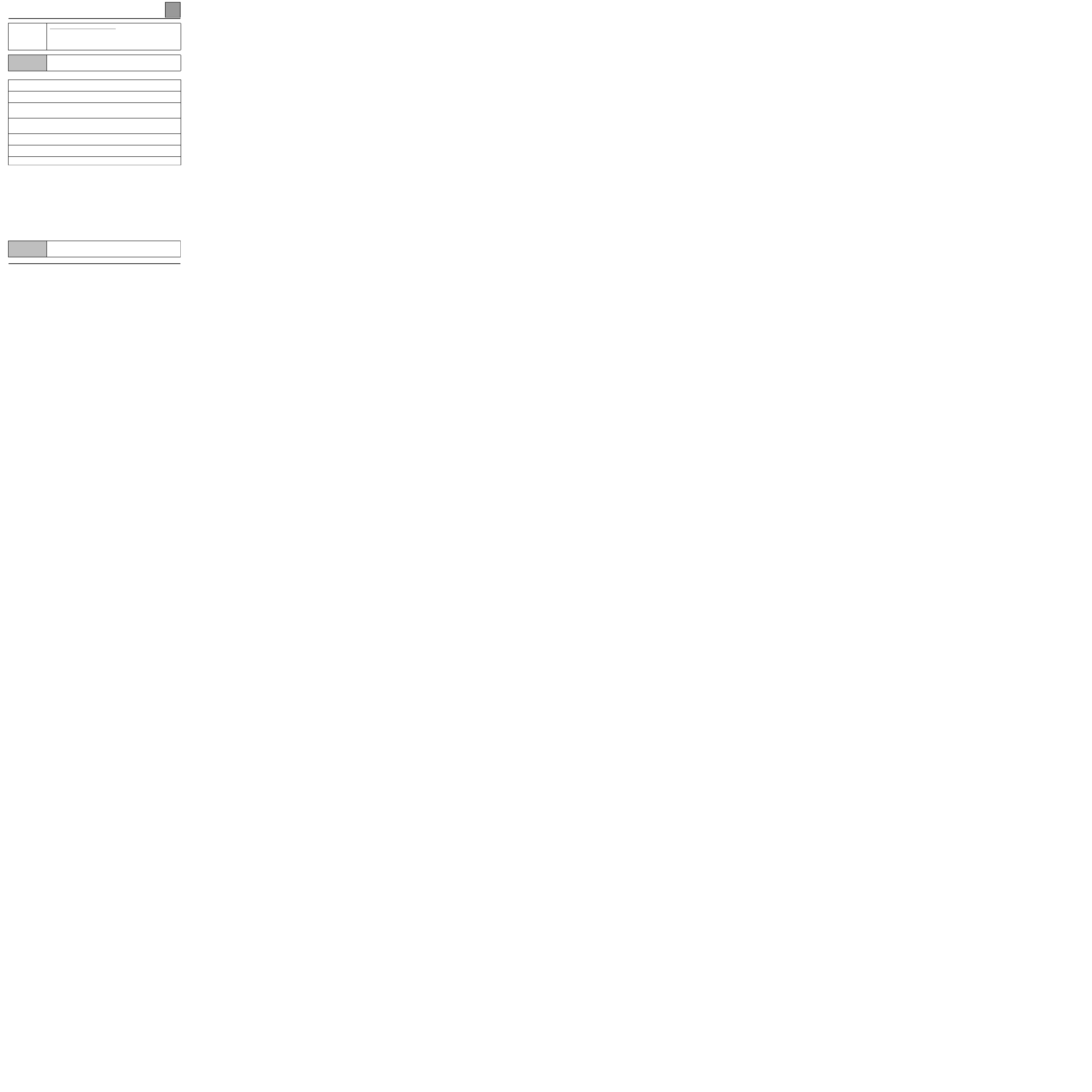
PASSENGER COMPARTMENT CONNECTION UNIT
Diagnostics - Status Interpretation
87
87-33
ET035
Windscreen wiper intermittent facility
NOTES
Use bornier Elé 1506 for the measures.
Check fuse F12.
Replace the fuse if necessary.
Check the earth in track 7 of the switch.
Repair if necessary.
With the switch in intermittent position, check the resistance between tracks A7 and A1 which must be between
30 ohms/10 kohms.
If the value is incorrect, replace the switch.
Check the connection in track A1 of the switch and in track 7 of the passenger compartment connection unit
yellow 26 track connector (B).
Repair if necessary.
Check the supply in track 16 of the passenger compartment connection unit black 16 track connector (D).
Replace the passenger compartment connection, if necessary.
Check the connection track 16 of the black 16 track connector (D) and track A1 of the wiper motor.
Repair if necessary.
If the fault persists, replace the wiper motor.
AFTER REPAIR
Check the passenger compartment connection unit configuration.

PASSENGER COMPARTMENT CONNECTION UNIT
Diagnostics - Status Interpretation
87
87-34
ET050
Rear screen wiper control
NOTES
For vehicle with opening rear screen.
For vehicles fitted with an opening rear screen, check that the screen is shut properly.
Check fuse F15.
Replace the fuse if necessary.
Check the BUS connection in track 4 of the passenger compartment connection unit Bii 26 track connector (A)
and track 3 of the tailgate module 18 track connector.
Repair if necessary.
Check the tailgate and rear screen switches.
Check the earth of the tailgate module in track 1.
Replace the tailgate module if the earth is correct.
Check the + 12 volts in track B4 of the wiper stalk.
Repair if necessary.
Check the + 12 volts in track B2 of the switch in rear screen wiper position.
Replace the switch if the + 12 volts is not present.
Check the + 12 volts in track 12 of the passenger compartment connection unit yellow 26 track connector (B).
Repair if necessary.
If the fault persists, replace the passenger compartment connection unit.
AFTER REPAIR
Check that the wipers operate correctly.

PASSENGER COMPARTMENT CONNECTION UNIT
Diagnostics - Status Interpretation
87
87-35
ET051
Low speed windscreen wiper control
NOTES
Illuminated when the switch is in low speed position.
Check fuse F12.
Replace the fuse if necessary.
Check the earth in track 7 of the switch.
With the switch in low speed position, check the earth in track A3.
Replace the switch if necessary.
Check the connection in track A3 of the switch and in track 20 of the passenger compartment connection unit
yellow 26 track connector (B).
Repair if necessary.
Check the supply in track 16 of the passenger compartment connection unit black 16 track connector (D).
Replace the passenger compartment connection.
Check the connection track 16 of the black 16 track connector (D) and track A1 of the wiper motor.
Repair if necessary.
If the fault persists, replace the wiper motor.
AFTER REPAIR
Check that the wipers operate correctly.
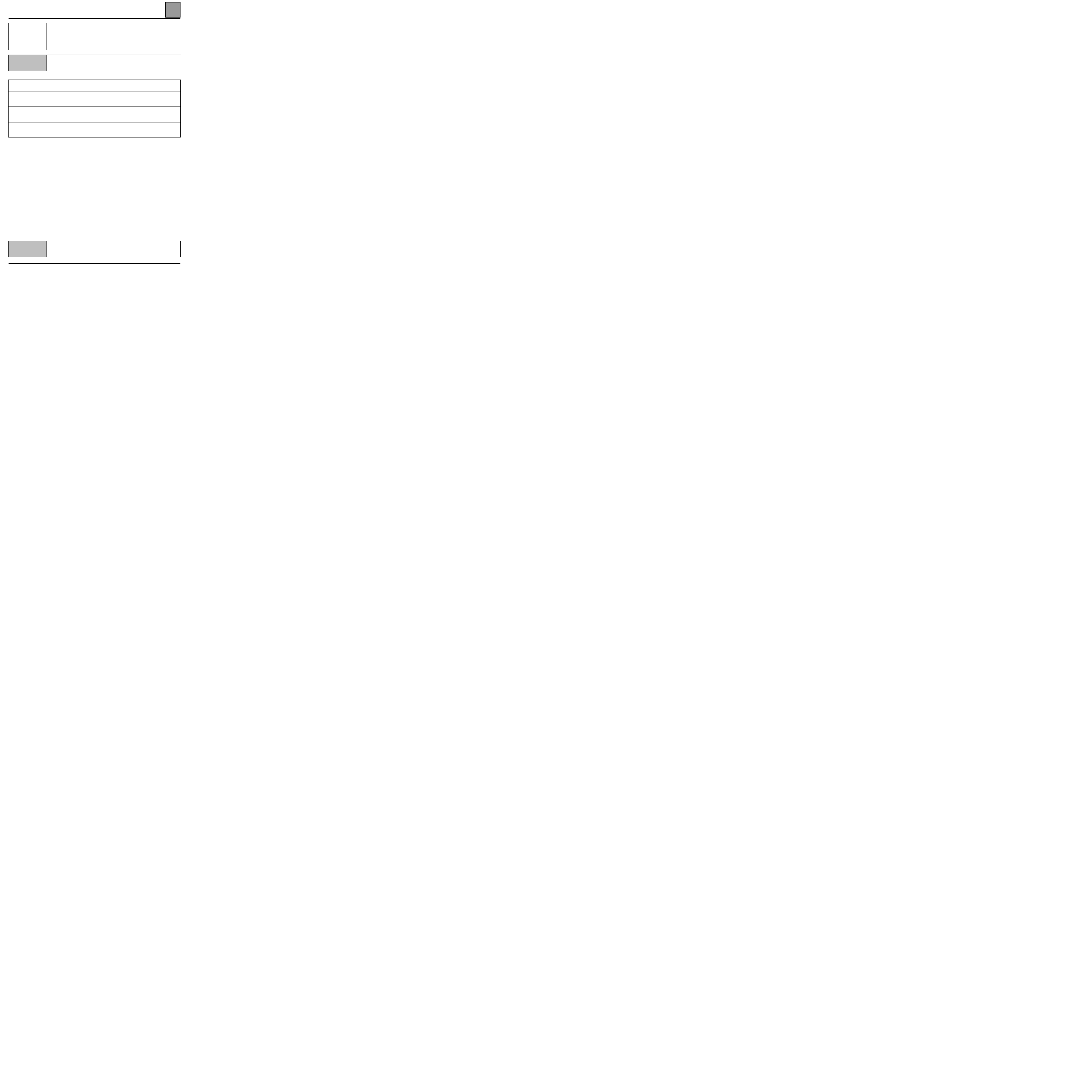
PASSENGER COMPARTMENT CONNECTION UNIT
Diagnostics - Status Interpretation
87
87-36
ET052
High speed windscreen wiper control
NOTES
Illuminated when the switch is at high speed.
With the switch in high speed position, check the earth in track A2 of the switch.
Repair if necessary.
Check the connection in track A2 of the switch and in track 6 of the passenger compartment connection unit
yellow 26 track connector (B).
If no continuity, replace the passenger compartment connection unit Bii.
Check the presence of + 12 volts in track 8 on the passenger compartment connection unit black 16 track
connector (D).
Repair if necessary.
Check the continuity between track 8 on the passenger compartment connection unit black 16 track
connector (D) and the wiper motor in track B1.
If there is continuity, replace the wiper motor.
AFTER REPAIR
Check that the wipers operate correctly.
PASSENGER COMPARTMENT CONNECTION UNIT
Diagnostics - Status Interpretation
87
87-37
ET082
Heated seat key
NOTES
Illuminated when the control is activated.
Check the earth in track A1 of the seat button.
Repair if necessary.
Operate the button and check the earth track B1 (warning, there is a diode).
Replace the button if necessary.
Check the earth in track 12 of the blue 12 track connector (F).
Repair if necessary.
If the fault persists, check the bulbs.
AFTER REPAIR
Check that the wipers operate correctly.

PASSENGER COMPARTMENT CONNECTION UNIT
Diagnostics - Status Interpretation
87
87-38
ET096
Seat belt warning device
NOTES
Driver's belt engaged.
Check the earth in track 22 of the passenger compartment connection unit Bii yellow 26 track connector (A).
Repair if necessary.
If the fault persists, replace the passenger compartment connection unit Bii.
AFTER REPAIR
Check that the wipers operate correctly.

PASSENGER COMPARTMENT CONNECTION UNIT
Diagnostics - Status Interpretation
87
87-39
ET098
Unlocking control
NOTES
Illuminated when pressing on the button in unlocking position.
Use bornier Elé 1506 for the measures.
Check the earth in track B2 of the button.
Repair if necessary.
With the button kept in locking position, check the earth in track B3.
Replace the button if necessary.
With the button kept in locking position, check the earth in track 5 of the passenger compartment connection unit
yellow 26 track connector (B).
Repair if necessary.
Check the presence of + 12 volts in track 7 of the black 16 track connector (D) button kept in locking position.
If the + 12 volts is not present, replace the passenger compartment connection unit.
Check track 7 connection of the black 16 track connector (D) and track 3 of the door motors, track 1 for the fuel
tank flap.
Repair if necessary.
If the fault persists, replace the motor.
AFTER REPAIR
Check that the wipers operate correctly.

PASSENGER COMPARTMENT CONNECTION UNIT
Diagnostics - Status Interpretation
87
87-40
ET099
Locking control
NOTES
Illuminated when pressing on the button in locking position.
Use bornier Elé 1506 for the measures.
Check the earth in track B2 of the button.
Repair if necessary.
With the button kept in locking position, check the earth in track A1.
Replace the button if necessary.
With the button kept in locking position, check the earth in track 18 of the passenger compartment connection
unit yellow 26 track connector (B).
Repair if necessary.
Check the presence of 12 volts in track 6 of the black 16 track connector (D) button kept in locking position.
If the + 12 volts is not present, replace the passenger compartment connection unit.
Check track 6 connection of the black 16 track connector (D) and track 1 of the door motors, track 3 for the fuel
tank flap.
Repair if necessary.
If the fault persists, replace the motor.
AFTER REPAIR
Check that the wipers operate correctly.
PASSENGER COMPARTMENT CONNECTION UNIT
Diagnostics - Status Interpretation
87
87-41
ET114
Electric window automatic rewinding
NOTES
Illuminated when the control is in operation.
Use bornier Elé 1506 for the measures.
On the fault finding tool, start the window raising and lowering controls.
Check that the window operates correctly.
With the bornier in place, check the continuity of the line:
– in track 24 of the yellow 26 track connector (A) and track A2 of the window lift button,
– in track 11 of the yellow 26 track connector (A) and track B2 of the window lift button,
Repair if necessary.
Check the driver's window lift button earth in track 3.
Repair if necessary.
If the fault persists, replace the driver's window lift.
Position the bornier, start the window raising and lowering controls.
Check the voltage between tracks 3 and 4 of the black 16 track connector (D):
– through the raise control = + 12 volts.
– through the lower control = - 12 volts.
Replace the passenger compartment connection unit BII if the voltage levels are not correct.
Check the continuity in track 3 of the passenger compartment connection unit black 16 track connector (D) and
the track 2 of the window lift motor.
Check the continuity in track 4 of the black 16 track connector (D) track 1 of the window lift motor.
Repair if necessary.
If the fault persists, replace the window lift motor.
AFTER REPAIR
Check that the wipers operate correctly.
Check the passenger compartment connection unit configuration.

PASSENGER COMPARTMENT CONNECTION UNIT
Diagnostics - Status Interpretation
87
87-42
ET120
Right front door open
NOTES
Illuminated if door open.
NOTE:
Interior lights normal operation:
– With the radio frequency plip remote control
Illumination of interior lights:
– Front and central console
– Second line
Timed period when doors closed.
– On opening the front door:
Illumination of interior lights:
– Front and central console
– Second line.
Timed period when doors closed.
– On opening the rear door:
Illumination of interior lights:
– Front and central console
– Second line.
– Third line
– Luggage compartment.
extinguish after timed period
extinguish immediately
AFTER REPAIR
Check that the wipers operate correctly.

PASSENGER COMPARTMENT CONNECTION UNIT
Diagnostics - Status Interpretation
87
87-43
ET120
(Continued)
NOTES
Check fuse F28 and check that 12 volts is present in track 2 of the interior lights.
Put the interior lights in "door" position.
Check the lines between the passenger compartment connection unit and the door switches. In track A of the
switch:
– In track 18 of the connection unit yellow 26 track connector (A) for the left front switch.
– In track 23 of the connection unit yellow 26 track connector (A) for the right front switch.
– In track 9 of the connection unit yellow 26 track connector (A) for the rear doors' switch.
Repair if necessary.
Check the earth in track B of the door switch.
Repair if necessary.
If the fault persists, replace the switch.
Check the earth in track 12 of the passenger compartment connection unit yellow 26 track connector (A).
Replace the passenger compartment connection unit BII if the earth is not present.
Check the lines between track 12 of the passenger compartment connection unit yellow 26 track connector (A).
In track 3, for the right front interior lights and the 2
nd
right line and front console lights.
Repair if necessary.
If the fault persists, replace the bulb.
AFTER REPAIR
Check that the wipers operate correctly.

PASSENGER COMPARTMENT CONNECTION UNIT
Diagnostics - Status Interpretation
87
87-44
ET121
Left front door open
NOTES
Illuminated if door open.
NOTE:
Interior lights normal operation:
– With the radio frequency plip remote control
Illumination of interior lights:
– Front and central console
– Second line
Timed period when doors closed.
– On opening the front door:
Illumination of interior lights:
– Front and central console
– Second line.
Timed period when doors closed.
– On opening the rear door:
Illumination of interior lights:
– Front and central console
– Second line.
– Third line
– Luggage compartment.
extinguish after timed period
extinguish immediately
AFTER REPAIR
Check that the wipers operate correctly.

PASSENGER COMPARTMENT CONNECTION UNIT
Diagnostics - Status Interpretation
87
87-45
ET121
(Continued)
NOTES
Check fuse F28 and check that 12 volts is present in track 2 of the interior lights.
Put the interior lights in "door" position.
Check the lines between the passenger compartment connection unit and the door switches. In track A of the
switch:
– In track 18 of the connection unit yellow 26 track connector (A) for the left front switch.
– In track 23 of the connection unit yellow 26 track connector (A) for the right front switch.
– In track 9 of the connection unit yellow 26 track connector (A) for the rear doors' switch.
Repair if necessary.
Check the earth in track B of the door switch.
Repair if necessary.
If the fault persists, replace the switch.
Check the earth in track 12of the passenger compartment connection unit yellow 26 track connector (A).
Replace the passenger compartment connection unit BII if the earth is not present.
Check the lines between track 12 of the passenger compartment connection unit yellow 26 track connector (A).
In track 1, for the left front interior lights and 2
nd
left line light.
Repair if necessary.
If the fault persists, replace the bulb.
AFTER REPAIR
Check that the wipers operate correctly.
PASSENGER COMPARTMENT CONNECTION UNIT
Diagnostics - Status Interpretation
87
87-46
ET122
Rear door open
NOTES
Illuminated if door open.
NOTE:
Interior lights normal operation:
– With the radio frequency plip remote control
Illumination of interior lights:
– Front and central console
– Second line
Timed period when doors closed.
– On opening the front door:
Illumination of interior lights:
– Front and central console
– Second line.
Timed period when doors closed.
– On opening the rear door:
Illumination of interior lights:
– Front and central console
– Second line.
– Third line
– Luggage compartment.
extinguish after timed period
extinguish immediately
AFTER REPAIR
Check that the wipers operate correctly.

PASSENGER COMPARTMENT CONNECTION UNIT
Diagnostics - Status Interpretation
87
87-47
ET122
(Continued)
NOTES
Check fuse F28 and check that 12 volts is present in track 2 of the interior lights.
Put the interior lights in "door" position.
Check the lines between the passenger compartment connection unit and the door switches. In track A of the
switch:
– In track 18 of the connection unit yellow 26 track connector (A) for the left front switch.
– In track 23 of the connection unit yellow 26 track connector (A) for the right front switch.
– In track 9 of the connection unit yellow 26 track connector (A) for the rear doors' switch.
Repair if necessary.
Check the earth in track B of the door switch.
Repair if necessary.
If the fault persists, replace the switch.
Check the earth in track 12of the passenger compartment connection unit yellow 26 track connector (A).
Replace the passenger compartment connection unit BII if the earth is not present.
Check the lines between track 12 of the passenger compartment connection unit yellow 26 track connector (A).
– In track 1, for the 2
nd
left line light.
– In track 9, for the 2
nd
right line light.
Repair if necessary.
If the fault persists, replace the bulb.
AFTER REPAIR
Check that the wipers operate correctly.

PASSENGER COMPARTMENT CONNECTION UNIT
Diagnostics - Status Interpretation
87
87-48
ET123
Tailgate open
NOTES
Check fuse F28 and check that 12 volts is present in track 2 of the interior lights.
Put the interior lights in "door" position.
Check the lines between the passenger compartment connection unit and the tailgate module:
– In track 4 of the connection unit yellow 26 track connector (A) for the left front switch.
– In track 3 of the tailgate module connector.
Repair if necessary.
Check the earth in track 1 of the door switch (tailgate open).
Repair if necessary.
If the fault persists, replace the switch.
Check the earth in track 4 of the tailgate module (tailgate open).
Replace the tailgate module if the earth is not present.
AFTER REPAIR
Check that the wipers operate correctly.

PASSENGER COMPARTMENT CONNECTION UNIT
Diagnostics - Status Interpretation
87
87-49
ET138
ADAC button pushed in
NOTES
None
Check the earth in track B5 of the switch.
Repair if necessary.
Check the earth in track B7 of the switch by pushing the ADAC control.
Replace the switch if necessary.
Check the earth in track 19 of the passenger compartment connection unit Bii yellow 26 track connector (B).
Repair if necessary.
If the fault persists, replace the passenger compartment connection unit Bii.
AFTER REPAIR
Check that the wipers operate correctly.
PASSENGER COMPARTMENT CONNECTION UNIT
Diagnostics - Status Interpretation
87
87-50
ET141
Reversing engaged
NOTES
Use bornier Elé 1506 for the measures.
Manual gearbox
With the reversing control engaged, check fuses F18 and F13.
Replace the fuse(s) if necessary.
Check the 12 volts on the reversing switch.
Replace the switch if necessary.
Check the 12 volts on the reversing lights in track 2.
Repair if necessary.
If the fault persists, check the bulbs.
Automatic transmission
With the reversing control engaged, check fuses F18 and F13.
Replace the fuse(s) if necessary.
Check the 12 volts on the multifunction switch.
Replace the switch if necessary.
Check the 12 volts on the reversing lights in track 2 for the left and in track 5 for the right.
Repair if necessary.
If the fault persists, check the bulbs.
AFTER REPAIR
Check that the wipers operate correctly.

PASSENGER COMPARTMENT CONNECTION UNIT
Diagnostics - Status Interpretation
87
87-51
ET171
Preheating phase
NOTES
For diesel vehicles only. Two cases are dealth with:
– ET133 remains extinguished when switching on
– ET133 remains illuminated without the preheating
function
Use bornier Elé 1506 for the measures.
: case 1
: case 2
Case 1
The status does not illuminate, check:
– The continuity between track 24 of the passenger compartment connection unit (BII)
blue 26 track connector (F) and track XX of the diesel injection computer.
Case 2
If the status remains illuminated without the preheating function, check:
– The insulation between track 24 of the passenger compartment connection unit (Bii)
blue 26 track connector (F) and the earth.
AFTER REPAIR
Restart the conformity check from the beginning.
Document Outline
- Contents
- 62-AIR CONDITIONING
- 80-DISCHARGE BULB
- 82-IMMOBILISER
- 83-Instrument panel
- 87-PASSENGER COMPARTMENT CONNECTION UNIT
Wyszukiwarka
Podobne podstrony:
Engine Management Fault Finding
Fault Finding And Troubleshooting
ABS Fault Finding
C102974 A SERVICE FAULT FINDING
ABS Fault Finding
3625A INDEPENDANT HEATER FAULT FINDING
3726A Fault Finding Petrol Injection
Air Conditioning Fault Finding
Engine Management Fault Finding
Popular Mechanics Finding And Fixing Water And Air Leaks
002 Z Pomoca Latwiej Gdzie je pomoc dydaktycznaid 2241
Tkaniy z włókna octanowego, Pielęgnacja materiałów - jak je prać
Tkaniy ażurowe, Pielęgnacja materiałów - jak je prać
Czym jest myślenie twórcze i jak je rozwijać
Morfologia komorek drozdzy je je je
więcej podobnych podstron