
Heating and ventilation
AIR CONDITIONING
77 11 304 422
"The repair methods given by the manufacturer in this document are based on the
technical specifications current when it was prepared.
The methods may be modified as a result of changes introduced by the manufacturer
in the production of the various component units and accessories from which his
vehicles are constructed."
JUNE 2001
All copyrights reserved by Renault.
EDITION ANGLAISE
Copying or translating, in part or in full, of this document or use of the service part
reference numbering system is forbidden without the prior written authority of Renault.
© RENAULT 2001

Air conditioning
Contents
Page
62
AIR CONDITIONING
Manual air conditioning.
Introduction
62-1
Customer complaints
62-2
Fault finding chart
62-3
Automatic air conditioning.
Introduction
62-27
Interpretation of faults
62-29
Conformity check
62-37
Status interpretation
62-43
Parameter interpretation
62-49
Customer complaints
62-51
Fault finding chart
62-51
AIR CONDITIONING'
Fault finding - Introduction
62
62-1
Manual
162
AIR CONDITIONING'
Fault finding - Introduction
GENERAL APPROACH TO FAULT FINDING
– Locate the Fault finding documents corresponding to the system identified.
– Take note of information contained in the introductory sections.
SPECIAL FEATURES OF THE MANUAL CLIMATE CONTROL SYSTEM
The cold loop is controlled by the injection computer and the heating and ventilation mixing and distribution are
manually controlled, therefore the climate control computer does not record any faults that can be processed by
the diagnostic tool.
All faults related to the cold loop, compressor, pressure switch, fan assembly, charge circuit, are diagnosed by the
injection computer
, to which air conditioning circuit operation requests are transmitted on behalf of the climate
control computer. See injection computer fault finding for a complete fault finding operation on the cold loop.
This note covers only looking for faults as a result of customer complaints.
DEALING WITH CUSTOMER COMPLAINTS
This section has fault finding charts, which suggest a series of possible causes of problems. These lines of research
are only to be used when the climate control system is not functioning correctly and after a complete fault
finding procedure on the cold loop by means of the injection diagnostic has been performed.
COMPUTER CONNECTOR CORRESPONDENCES:
– Green computer 15-track connector: connector A
– Black computer 10-track connector: connector B
This document contains generic fault-finding procedures that apply to all manual climate control
computers fitted to the Clio II from June 2001 (Europe version).
To undertake fault finding on this system, it is essential to have the following items available:
– This section of the Fault-finding Workshop Repair Manual,
– The wiring diagram of the function for the vehicle concerned,
– A multimeter.
CAMANX65 1.1
AIR CONDITIONING'
Fault finding - Customer complaints
62
62-2
Manual
Fault finding - Customer complaints
NOTES
Before working on the vehicle, check that the client is using the heating and ventilation
system correctly.
FAULTY AIR DISTRIBUTION
FAULTY AIR DISTRIBUTION
CHART 1
AIR FLOW PROBLEM
CHART 2
INEFFICIENT WINDSCREEN DEMISTING
CHART 3
POOR VENTILATION PERFORMANCE
CHART 4
NO PASSENGER COMPARTMENT VENTILATION
CHART 5
NO AIR RECIRCULATION
CHART 6
FAULTY HEATING
NO HEATING OR INADEQUATE HEATING
CHART 7
TOO HOT
CHART 8
NO COLD AIR
CHART 9
AIR TOO COLD
CHART 10
POOR HEATING AND VENTILATION PERFORMANCE
CHART 11
HEATING INADEQUATE IN THE REAR
CHART 12
FUMES IN PASSENGER COMPARTMENT
UNPLEASANT ODOURS IN PASSENGER COMPARTMENT
CHART 13
WATER IN PASSENGER COMPARTMENT
WATER IS PRESENT IN PASSENGER COMPARTMENT
CHART 14
FAULTY CONTROL PANEL
CONTROL PANEL LIGHTING FAILURE
CHART 15
CONTROLS STIFF
CHART 16
CAMANX65 1.1
AIR CONDITIONING'
Fault finding - Fault finding chart
62
62-3
Manual
Fault finding - Fault finding chart
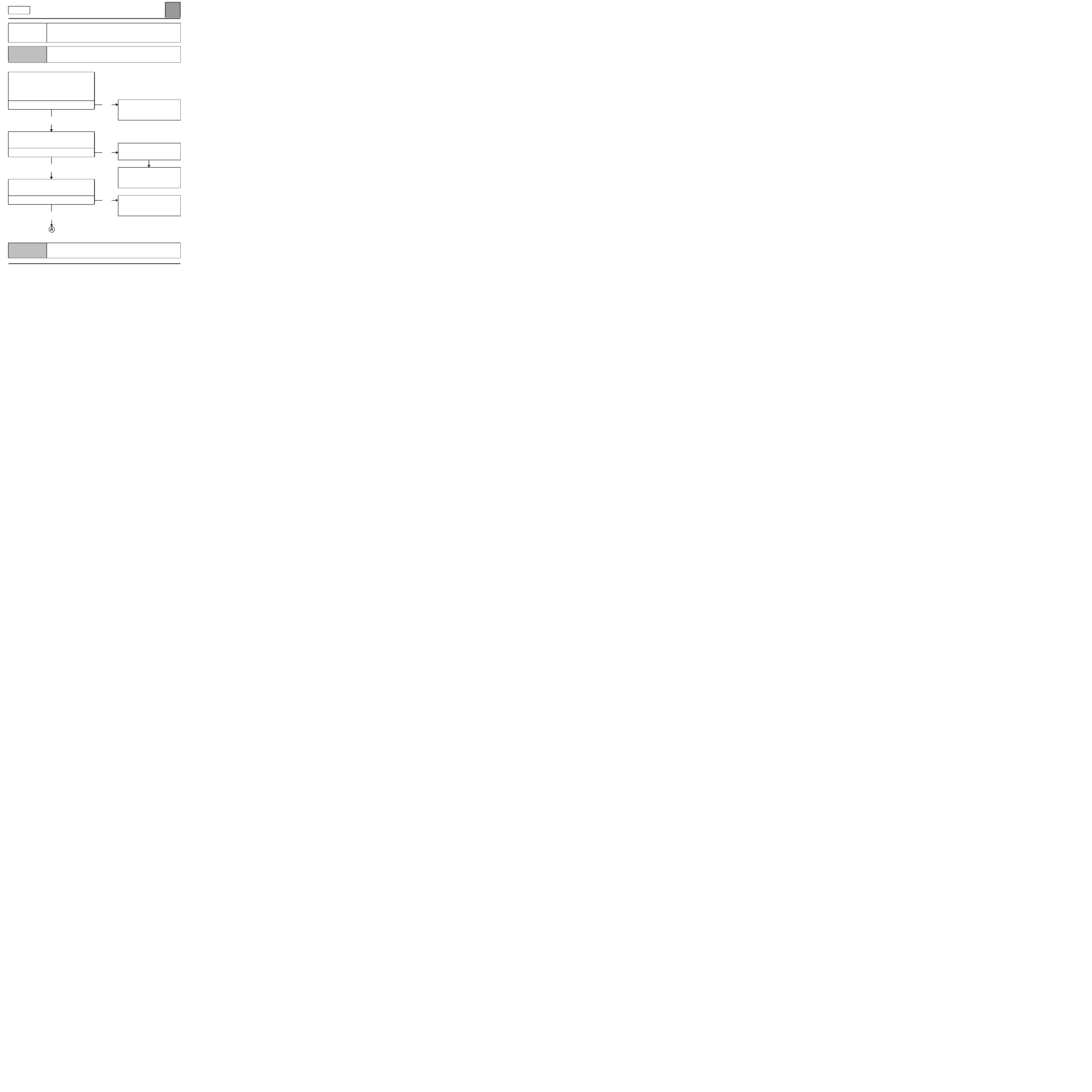
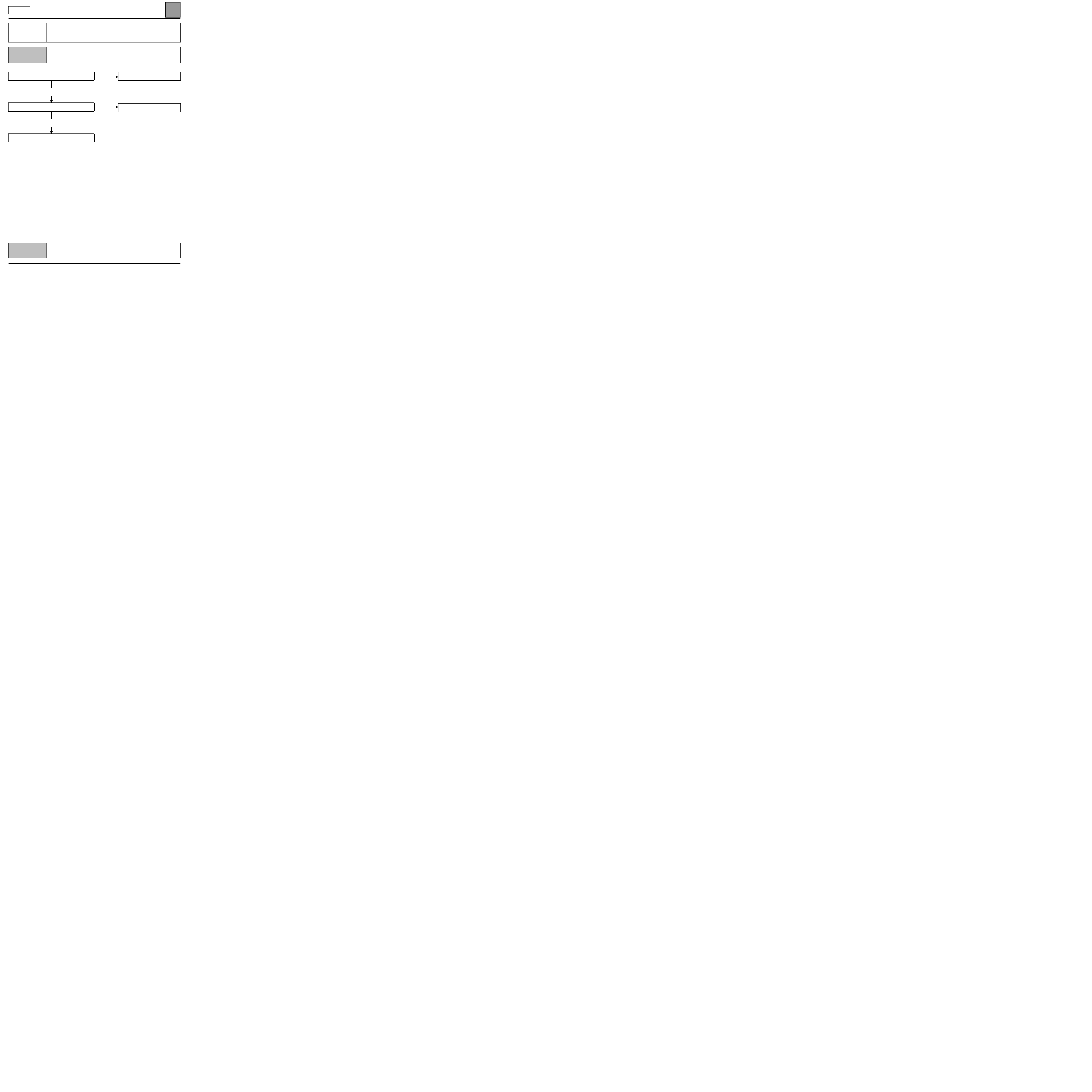
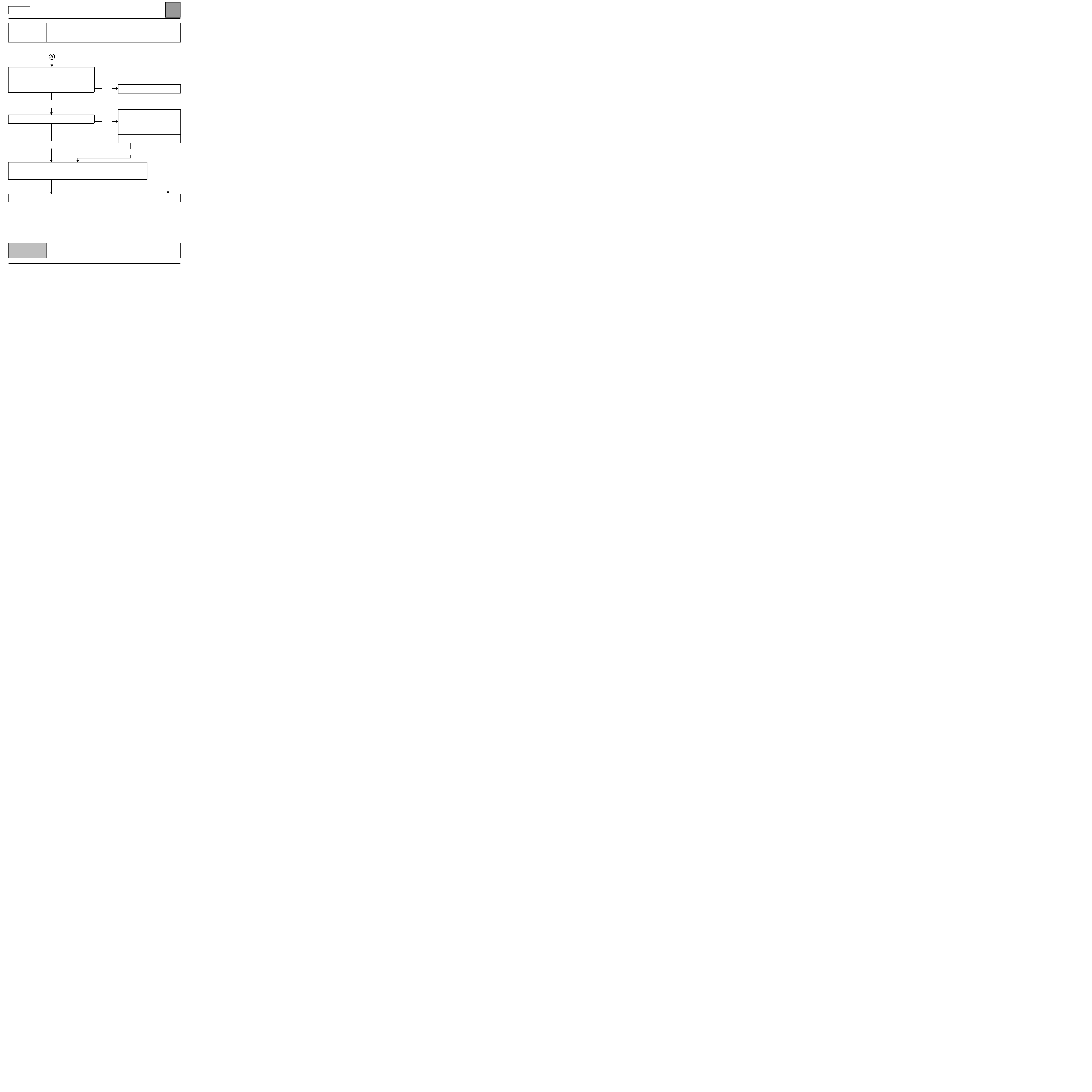
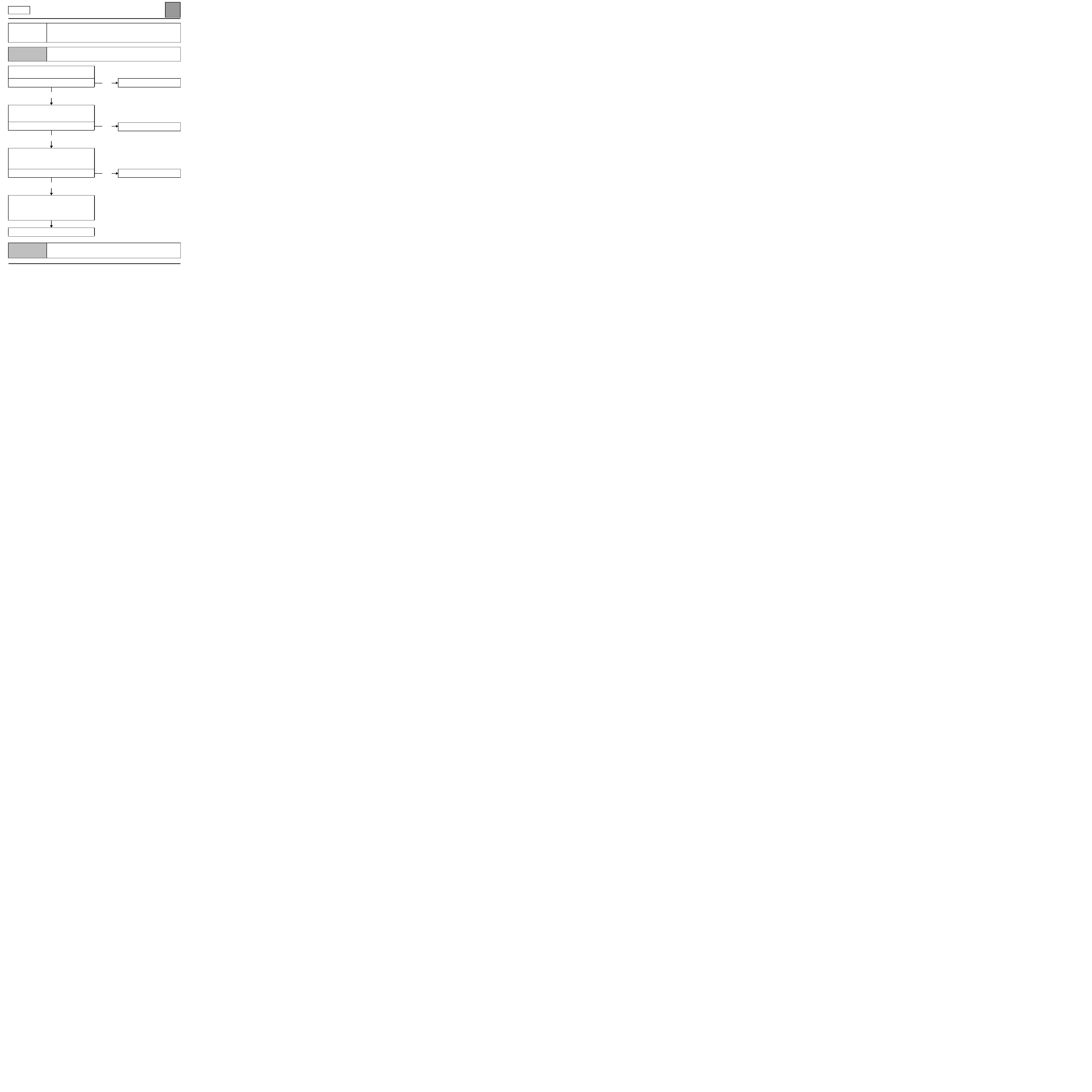
CHART 1
FAULTY AIR DISTRIBUTION
NOTES
Before working on the vehicle, check that the client is using the heating and ventilation
system correctly.
Switch the passenger compartment blower to full,
the temperature control to maximum heat or
maximum cold, and move the air distribution
control.
Check that the air outlet corresponds to the
selection.
Is the customer complaint confirmed?
yes
Check visually or by touch, on the right-hand side of
the air distribution unit, that moving the control
moves the sprockets and the lever.
Do they move?
yes
Check the connection of the cable to the air
distribution unit and the control panel and check the
condition of the cable and its retainer.
Is it correct?
yes
no
no
no
The air distribution is correct.
If necessary, explain how the
system works to the customer
again.
Check the air distribution flap
control wiring adjustment, the air
ducts and the air vents.
If the fault persists, remove the air
distribution unit and check the
distribution flaps.
Repair if necessary.
Replace the control cable, repair
the cable connection (clip) or
replace the faulty part (control
panel or distribution unit).
AFTER REPAIR
Check that the system is operating correctly.
CAMANX65 1.1
AIR CONDITIONING'
Fault finding - Fault finding chart
62
62-4
Manual
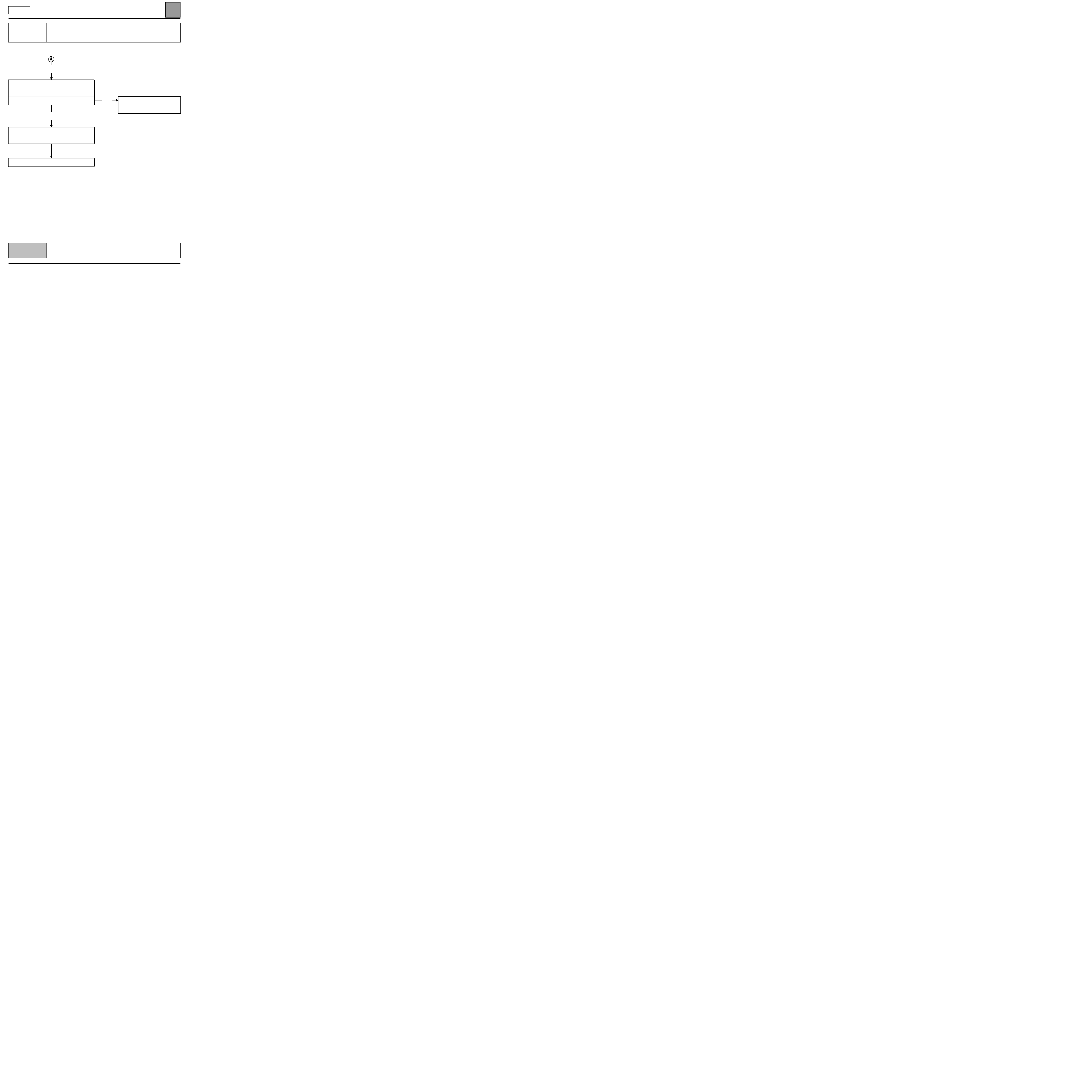
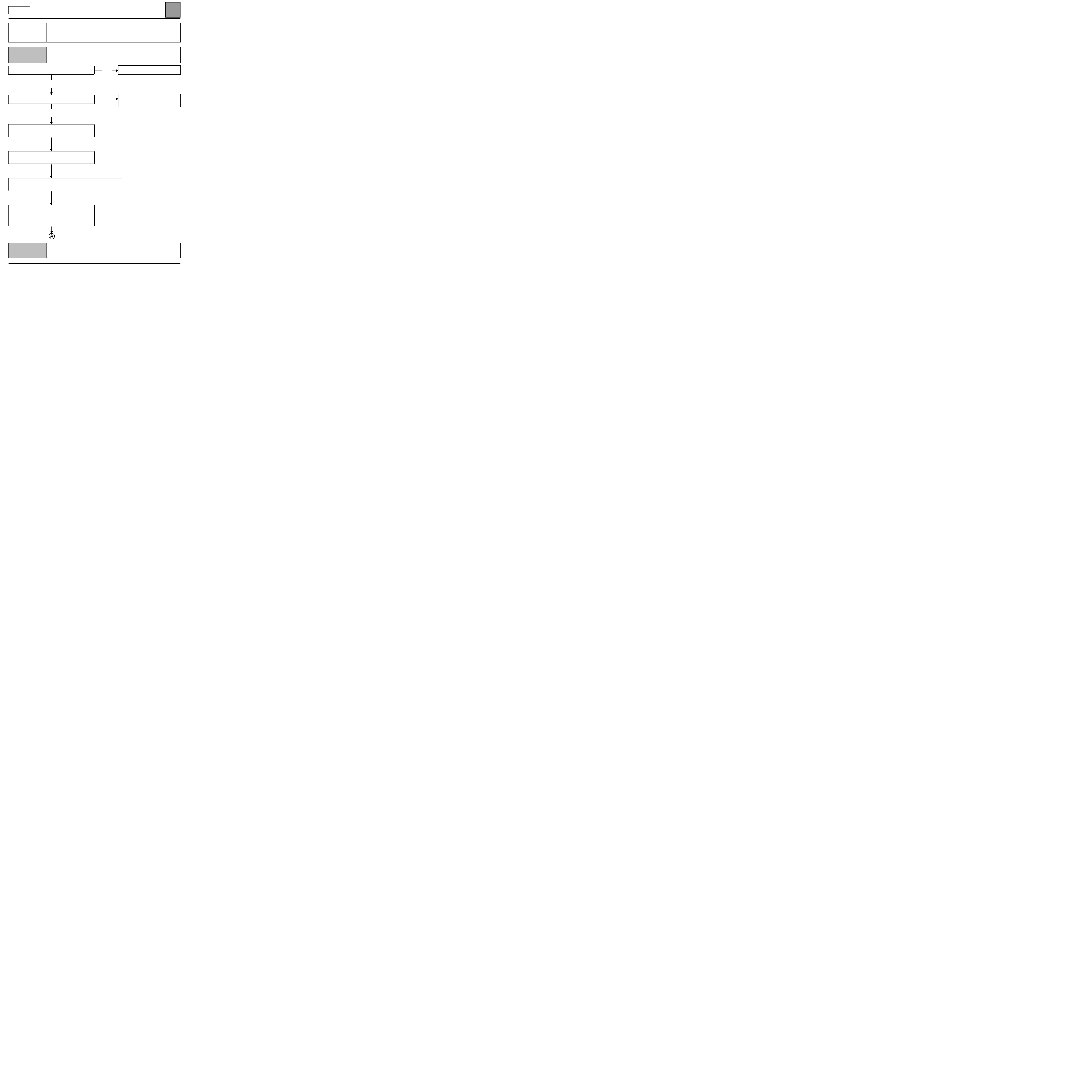
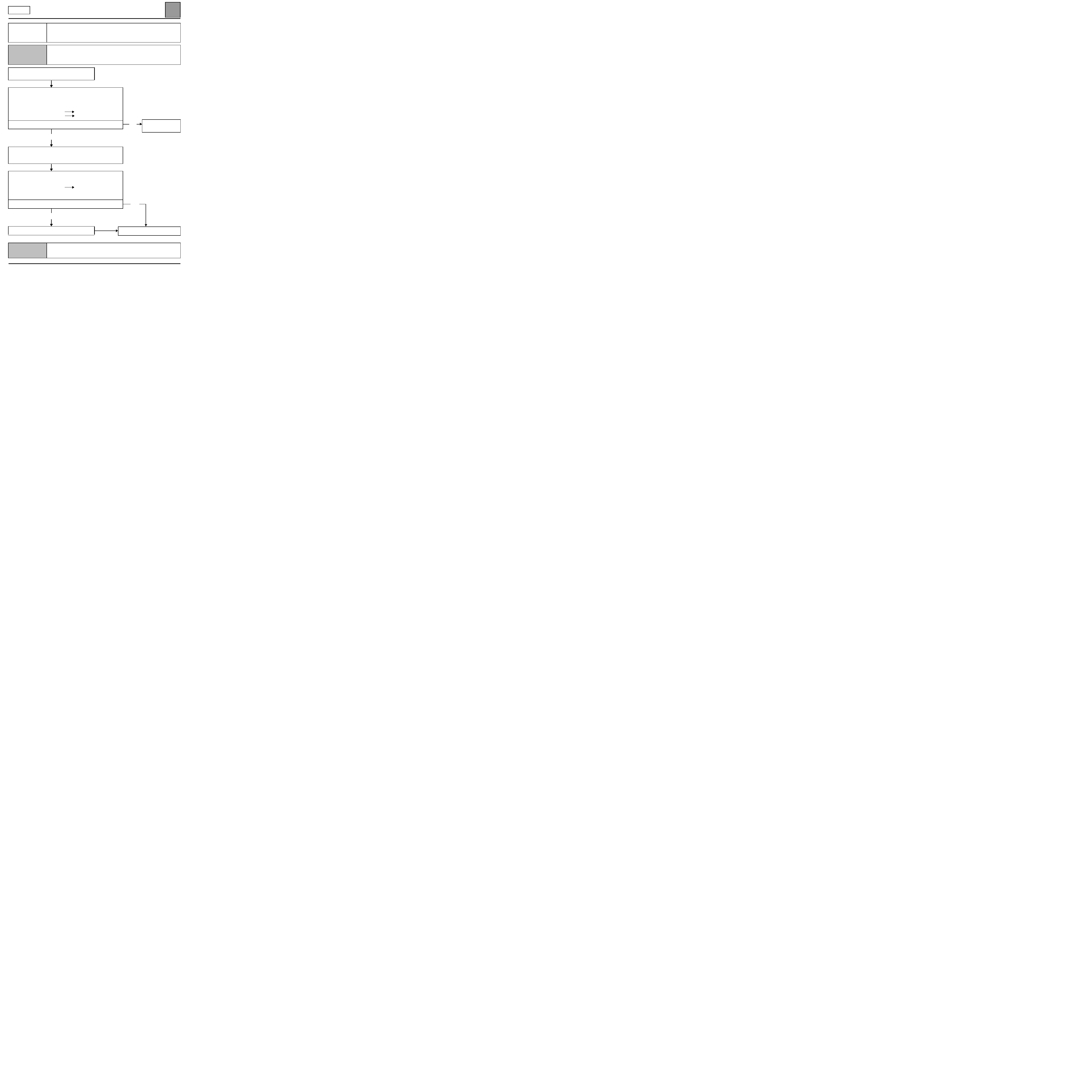
CHART 1
CONTINUED
yes
Check the condition of the kinematic (sprockets,
levers etc.) on the air distribution unit and the
control panel.
Is it correct?
yes
Remove the air distribution unit and check the
distribution flaps.
Repair or replace the assembly.
End of fault finding.
no
Repair if possible, otherwise
replace the distribution unit or the
control panel.
AFTER REPAIR
Check that the system is operating correctly.
CAMANX65 1.1
AIR CONDITIONING'
Fault finding - Fault finding chart
62
62-5
Manual
CHART 2
AIR FLOW PROBLEM
NOTES
Before working on the vehicle, check that the client is using the heating and ventilation
system correctly.
Special note:
– the resistor unit and the blower are located under the windscreen aperture on the
passenger side.
Is the passenger compartment blower
functioning
?
yes
Check that the air circuit (particle filter, scuttle panel grille, air vents and extractors etc.) is not blocked.
Check that the blower casing is in good condition and is fixed in its position.
Repair, clean or replace the particle filter if necessary.
Ensure that the blower unit is properly airtight.
Repair if necessary.
Check that the air recirculation flap is not stuck in air recirculation position using CHART 6.
Does the problem disappear when the air
distribution is changed?
no
Check the condition of the resistor unit black 15-track connector.
If necessary, repair or replace the connector.
Check the after ignition feeds in track 11 of connector A and in tracks A4 and A5 of connector B of the climate
control computer, as well as the earths in track 9 of connector A of the climate control computer and in tracks
14 and 15 of the resistor unit.
no
yes
Repair, see CHART 5.
Ensure that all the air vents are
open.
If the problem persists, refer to
CHART 1.
AFTER REPAIR
Check that the system is operating correctly.
CAMANX65 1.1
AIR CONDITIONING'
Fault finding - Fault finding chart
62
62-6
Manual
CHART 2
CONTINUED
Check that the speed selector on the control panel
is in correct working order, making sure that there is
an after ignition feed on tracks B5, B4, B1 and A1,
A2 of connector B of the climate control computer
respectively for speeds 1, 2, 3 and 4.
Disconnect the connector from the climate control computer and check the insulation, continuity and
absence of interference resistance
on the connections:
computer connector B track B5
track 3
resistor unit black 15-track connector
computer connector B track B4
track 4
resistor unit black 15-track connector
computer connector B track B1
track 5
resistor unit black 15-track connector
computer connector B track A1
track 12
resistor unit black 15-track connector
computer connector B track A2
track 13
resistor unit black 15-track connector
Repair if necessary.
Replace the resistor unit if the resistance is not
approximately:
speed 1 (track 3 and 12): 3.2
±
0.2
Ω
speed 2 (track 4 and 12): 1.5
±
0.2
Ω
speed 3 (track 5 and 12): 0.6
±
0.2
Ω
End of fault finding.
AFTER REPAIR
Check that the system is operating correctly.
CAMANX65 1.1
AIR CONDITIONING'
Fault finding - Fault finding chart
62
62-7
Manual
CHART 3
INEFFICIENT WINDSCREEN DEMISTING
NOTES
Special notes:
Check that the inside of the windows are not dirty, as this lowers the efficiency of the
demister.
Check that the air extractors are not blocked.
Repair if necessary.
Is the fault still present?
yes
Check that there are no water leaks into the
passenger compartment which would significantly
increase the humidity and reduce the effectiveness
of the demisting.
Repair if necessary (see CHART 14).
Is the fault still present?
yes
Is it an air distribution problem?
no
Is it an air flow problem?
no
Is it a heater performance problem?
no
no
no
yes
yes
yes
End of fault finding.
End of fault finding.
See CHART 1
See CHART 2
See CHART 7
AFTER REPAIR
Check that the system is operating correctly.
CAMANX65 1.1
AIR CONDITIONING'
Fault finding - Fault finding chart
62
62-8
Manual
CHART 3
CONTINUED
Check that the water condenser outlet is not blocked.
Repair if necessary.
Check that the recirculation flap is not blocked (see CHART 6).
Repair if necessary.
End of fault finding.
AFTER REPAIR
Check that the system is operating correctly.
CAMANX65 1.1
AIR CONDITIONING'
Fault finding - Fault finding chart
62
62-9
Manual
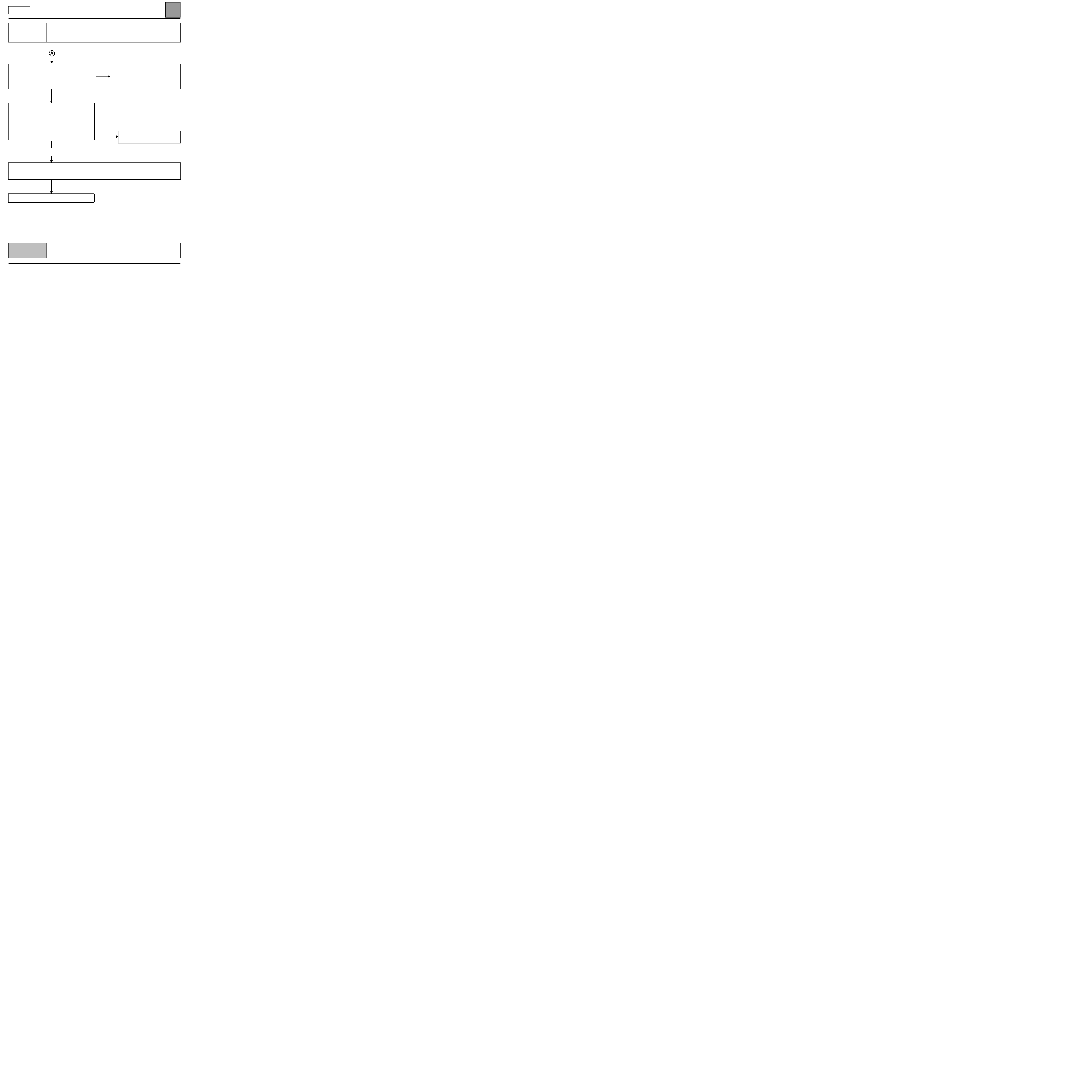
CHART 4
POOR VENTILATION PERFORMANCE
NOTES
Before working on the vehicle, check that the client is using the heating and ventilation
system correctly.
Is the air flow correct?
yes
Is the air distribution correct?
yes
End of fault finding.
no
no
See CHART 2
See CHART 1
AFTER REPAIR
Check that the system is operating correctly.
CAMANX65 1.1

AIR CONDITIONING'
Fault finding - Fault finding chart
62
62-10
Manual
CHART 5
NO PASSENGER COMPARTMENT VENTILATION
NOTES
Before working on the vehicle, check that the client is using the heating and ventilation
system correctly.
Special notes:
– the resistor unit and the blower are located under the windscreen aperture on the
passenger side.
Check that the fusesare in good condition.
Repair if necessary.
Check the condition of the resistor unit black 15-track connector.
If necessary, repair or replace the connector.
Check the after ignition feeds in track 11 of connector A and in tracks A4 and A5 of connector B of the climate
control computer, as well as the earths in track 9 of connector A of the climate control computer and in tracks
14 and 15 of the resistor unit black 15-track connector.
Check that the speed selector on the control panel is in correct working
order, making sure that there is an after ignition feed on tracks B5, B4,
B1 and A1, A2 of connector B of the climate control computer
respectively for speeds 1, 2, 3 and 4.
Disconnect the connector from the climate control computer and check the insulation, continuity and
absence of interference resistance
on the connections:
computer connector B track B5
track 3
resistor unit black 15-track connector
computer connector B track B4
track 4
resistor unit black 15-track connector
computer connector B track B1
track 5
resistor unit black 15-track connector
computer connector B track A1
track 12
resistor unit black 15-track connector
computer connector B track A2
track 13
resistor unit black 15-track connector
Repair if necessary.
AFTER REPAIR
Check that the system is operating correctly.
CAMANX65 1.1
AIR CONDITIONING'
Fault finding - Fault finding chart
62
62-11
Manual
CHART 5
CONTINUED
Replace the resistor unit if the resistance is not approximately:
speed 1 (track 3 and 12): 3.2
±
0.2
Ω
speed 2 (track 4 and 12): 1.5
±
0.2
Ω
speed 3 (track 5 and 12): 0.6
±
0.2
Ω
Check the condition of the engine cooling fan black 2-track connector.
If necessary, repair or replace the connector.
Disconnect the connector from the resistor unit and check the insulation, continuity and absence of
interference resistance
on the connections:
resistor unit black 15-track connector tracks 12 and 13
track 1
of the passenger
compartment blower connector
resistor unit black 15-track connector tracks 14 and 15
track 2
of the passenger
compartment blower connector
Repair if necessary.
Take the engine cooling fan apart and check its resistance.
Replace the engine cooling fan if the resistance is not approximately:
0.2
< R > 0.5
Ω
Ensure that the fan assembly casing is not broken or slipped out of
position.
Replace the fan assembly if necessary.
End of fault finding.
AFTER REPAIR
Check that the system is operating correctly.
CAMANX65 1.1
AIR CONDITIONING'
Fault finding - Fault finding chart
62
62-12
Manual
CHART 6
NO AIR RECIRCULATION
NOTES
Before working on the vehicle, check that the client is using the heating and ventilation
system correctly.
Special notes:
– the resistor unit, the blower and the recirculation flap are located under the
windscreen aperture on the passenger side.
Check that the fuses are in good condition.
Repair if necessary.
Check either visually or by listening that the
recirculation flap is in correct working order.
Is the flap functioning?
no
Check the after ignition feeds in track 11 of connector A and in tracks A4 and A5 of connector B of the climate
control computer, as well as the earths in track 9 of connector A of the climate control computer and in tracks
14 and 15 of the resistor unit black 15-track connector.
Check the condition of the resistor unit black
15-track connector.
If necessary, repair or replace the connector.
yes
Check the seals and the condition
of the air ducts, the recirculation
flap and the air vents making sure
that they are not blocked.
AFTER REPAIR
Check that the system is operating correctly.
CAMANX65 1.1
AIR CONDITIONING'
Fault finding - Fault finding chart
62
62-13
Manual
CHART 6
CONTINUED
Disconnect the connector from the climate control computer and check the insulation, continuity and
absence of interference resistance
on the connections:
computer connector A track 10
track 2
resistor unit black 15-track connector
computer connector A track 14
track 1
resistor unit black 15-track connector
Repair if necessary.
Check the resistance between tracks C and B of the resistor unit black
2-track connector.
If the resistance is not approximately 38
Ω
±
0.2
Ω
take the fan
assembly apart to gain access to the air recirculation motor.
Check the condition of the recirculation motor, and its supply group.
End of fault finding.
AFTER REPAIR
Check that the system is operating correctly.
CAMANX65 1.1

AIR CONDITIONING'
Fault finding - Fault finding chart
62
62-14
Manual
CHART 7
NO HEATING OR INADEQUATE HEATING
NOTES
Before working on the vehicle, check that the client is using the heating and ventilation
system correctly.
Is the air flow correct?
yes
Is the air distribution correct?
yes
With the engine warm, turn the heating on full.
Is the delivery air hot?
no
Check the condition and adjustment of the mixing
flap control cables.
Check the condition and correct working of the
mixing flap.
no
no
yes
See CHART 2, faulty air flow.
See CHART 1, faulty air
distribution.
If necessary, explain how the
system works to the customer
again.
AFTER REPAIR
Check that the system is operating correctly.
CAMANX65 1.1
AIR CONDITIONING'
Fault finding - Fault finding chart
62
62-15
Manual
CHART 7
CONTINUED
Check the seals and the condition of the air ducts,
the recirculation flap and the air vents making sure
that they are not blocked.
Is the problem still present?
yes
Are the heater matrix pipes on the bulkhead hot?
yes
Check that the heater matrix is not blocked, and clean or replace if necessary.
Is the fault still present?
End of fault finding.
no
no
yes
no
End of fault finding.
Carry out a check on the coolant
circuit and ensure that the
thermostatic valve opens at the
correct temperature.
Replace the valve if necessary.
Is the fault still present?
AFTER REPAIR
Check that the system is operating correctly.
CAMANX65 1.1
AIR CONDITIONING'
Fault finding - Fault finding chart
62
62-16
Manual
CHART 8
EXCESS HEATING
NOTES
Before working on the vehicle, check that the client is using the heating and ventilation
system correctly.
Is the air flow correct?
yes
Is the air distribution correct?
yes
Check the condition and setting of the mixing flap
control cable.
Check the condition and working order of the mixing
flap.
Check the seals and the condition of the air ducts, the recirculation
flap and the air vents making sure that they are not blocked.
Carry out a check on the coolant circuit and ensure
that the thermostatic valve opens at the correct
temperature.
Replace the valve if necessary.
no
no
See CHART 2, faulty air flow.
See CHART 1, faulty air
distribution.
AFTER REPAIR
Check that the system is operating correctly.
CAMANX65 1.1
AIR CONDITIONING'
Fault finding - Fault finding chart
62
62-17
Manual
CHART 8
CONTINUED
Check that the recirculation flap is in the external air position.
Repair if necessary.
End of fault finding.
AFTER REPAIR
Check that the system is operating correctly.
CAMANX65 1.1

AIR CONDITIONING'
Fault finding - Fault finding chart
62
62-18
Manual
CHART 9
NO COLD AIR
NOTES
Before working on the vehicle, check that the client is using the heating and ventilation
system correctly.
Is the air flow correct?
yes
Is the air distribution correct?
yes
Check for possible leaks in the air conditioning
circuit.
Check the charge of the refrigerant fluid (650 g
±
35 g).
Check the condition of the air conditioning compressor belt and its tension.
Repair if necessary.
Check the condition of the fuses.
Repair if necessary.
Check the condition of the climate control computer connector and the injection computer connectors.
Repair if necessary.
no
no
See CHART 2, faulty air flow.
See CHART 1, faulty air
distribution.
AFTER REPAIR
Check that the system is operating correctly.
CAMANX65 1.1
AIR CONDITIONING'
Fault finding - Fault finding chart
62
62-19
Manual
CHART 9
CONTINUED
Disconnect the connectors from the computers and check the insulation, continuity and absence of
interference resistance
on the connection:
climate control computer connector A track 12
injection computer (refer to the diagrams
for the model year and vehicle
concerned).
With the engine and heating and ventilation system
running, check a there is a 12-volt feed in track 12
of connector A of the climate control computer to
ensure that heating and ventilation requests are
being sent from the climate control computer to the
injection computer.
Is there a feed?
no
Check the after ignition feeds
in track 11 of connector A and in tracks A4 and A5 of connector B of the climate
control computer, as well as the earth in track 9 connector A of the climate control computer.
If the fault persists, replace the climate control computer.
End of fault finding.
yes
Test fully
the cold loop using the
injection fault finding procedure.
AFTER REPAIR
Check that the system is operating correctly.
CAMANX65 1.1

AIR CONDITIONING'
Fault finding - Fault finding chart
62
62-20
Manual
CHART 10
AIR TOO COLD
NOTES
Before working on the vehicle, check that the client is using the heating and ventilation
system correctly.
Is the air flow correct?
yes
Is the air distribution correct?
yes
Check the condition and adjustment of the mixing flap control cable.
Check the condition and the seals of the mixing flap.
Check the engine temperature is rising correctly.
If necessary, check and bleed the cooling circuit.
With the engine running and air conditioning switched off
check
that there is no heating and ventilation request from the climate control
computer to the injection computer in track 12 connector A of the
climate control computer.
If there a feed?
no
Check the injection system
using the diagnostic tool.
End of fault finding.
no
no
yes
See CHART 2, faulty air flow.
See CHART 1, faulty air
distribution.
Replace
the
climate control
computer.
AFTER REPAIR
Check that the system is operating correctly.
CAMANX65 1.1

AIR CONDITIONING'
Fault finding - Fault finding chart
62
62-21
Manual
CHART 11
POOR HEATING AND VENTILATION PERFORMANCE
NOTES
Before working on the vehicle, check that the client is using the heating and ventilation
system correctly.
Is the air flow correct?
yes
Is the air distribution correct?
yes
Check the condition and tension of the air conditioning compressor
belt.
Repair if necessary.
Is the fault still present?
yes
Check for possible leaks in the air conditioning system.
Check the charge of the refrigerant fluid (650 g
±
35 g).
Check that the recirculation flap is in correct working order.
Check the condition and adjustment of the control cable and replace it if
necessary.
Check that the mixing flap is in correct working order.
If the fault persists check the injection system using the diagnostic tool.
no
no
no
See CHART 2, faulty air flow.
See CHART 1, faulty air
distribution.
End of fault
finding.
End of fault
finding.
AFTER REPAIR
Check that the system is operating correctly.
CAMANX65 1.1

AIR CONDITIONING'
Fault finding - Fault finding chart
62
62-22
Manual
CHART 12
HEATING INADEQUATE IN THE REAR
NOTES
None.
Is the air flow correct?
yes
Is the air distribution correct?
yes
Check that the rear air vents behind the central
console are not blocked.
yes
Remove the central console and check that the
connection and sealing between the air distribution
unit and the heating duct to the rear seats is correct.
Repair if necessary.
End of fault finding.
no
no
no
See CHART 2, faulty air flow.
See CHART 1, faulty air
distribution.
Clear
the air outlets.
AFTER REPAIR
Check that the system is operating correctly.
CAMANX65 1.1
AIR CONDITIONING'
Fault finding - Fault finding chart
62
62-23
Manual
CHART 13
UNPLEASANT ODOURS IN PASSENGER COMPARTMENT
NOTES
None.
Check that the pollen filter is not blocked or worn.
Replace it if necessary.
Is the problem still present?
yes
Check that the evaporator outlet pipe is not
blocked.
Repair if necessary.
Is the problem still present?
yes
Check that the heating unit is completely tight
and there are no leaks
into the engine
compartment.
Repair if necessary.
Is the problem still present?
yes
Place the vehicle on a lift.
Run an extension through the evaporator outlet
pipe to apply the air conditioning freshener.
Spray in the complete contents of the can.
Leave the freshener to work for 15 minutes.
End of fault finding.
no
no
no
End of fault finding.
End of fault finding.
End of fault finding.
AFTER REPAIR
Check that the system is operating correctly.
CAMANX65 1.1

AIR CONDITIONING'
Fault finding - Fault finding chart
62
62-24
Manual
CHART 14
WATER IS PRESENT IN PASSENGER COMPARTMENT
NOTES
None.
Pressurise
the coolant circuit.
Is there any coolant leaking into the vehicle?
no
Check that the evaporator outlet pipe is not
blocked.
Repair if necessary.
Is the problem still present?
yes
The problem may be caused by ice in the
evaporator.
Does the customer complain of water droplets
coming out of the air vents?
yes
Repair.
End of fault finding.
yes
no
no
Repair.
End of fault finding.
The leak does not come from the
air conditioning system.
AFTER REPAIR
Check that the system is operating correctly.
CAMANX65 1.1
AIR CONDITIONING'
Fault finding - Fault finding chart
62
62-25
Manual
CHART 15
CONTROL PANEL LIGHTING FAILURE
NOTES
Special notes:
The control panel only lights up when the side lights are operated.
There is a shunt in place of the dimmer on models with manual heating and ventilation
systems.
Check the condition of the fuses.
Repair if necessary.
Check the connection and condition of the computer output
connectors.
Disconnect the connector from the computer and check the insulation,
continuity and absence of interference resistance
on the
connections:
computer connector A track 15
track 3
of the lighting shunt
earth
track 1
of the lighting shunt
Is the problem still present?
yes
When the ignition is on, check that there is a feed on track 13 connector
A of the climate control computer.
Repair if necessary.
Disconnect the connector from the computer and check the insulation,
continuity and absence of interference resistance
on the
connection:
computer connector A track 13
+ side lights
(refer to diagrams for the vehicle and year of make in question).
Repair if necessary.
Is the problem still present?
yes
Replace
the computer (control panel).
no
no
End of fault
finding.
End of fault finding.
AFTER REPAIR
Check that the system is operating correctly.
CAMANX65 1.1

AIR CONDITIONING'
Fault finding - Fault finding chart
62
62-26
Manual
CHART 16
CONTROLS STIFF
NOTES
This customer complaint applies to both manual controls, the air distribution control
and the mixing control.
Check the travel of the control cable.
Eliminate possible stresses (bending, restraining).
Repair if necessary.
Is the problem still present?
yes
Unfasten the cable on the side of the fan and check
the manoeuvrability of each part, control button
and flap control.
Is it correct?
yes
If the fault persists, replace the flap control cable.
End of fault finding.
no
no
End of fault finding.
Replace the control panel or the
flap unit.
AFTER REPAIR
Check that the system is operating correctly.
CAMANX65 1.1
AUTOMATIC AIR CONDITIONING
Fault finding - Introduction
62
62-27
CAREG
VDIAG No.: 06
162
AUTOMATIC AIR CONDITIONING
Fault finding - Introduction
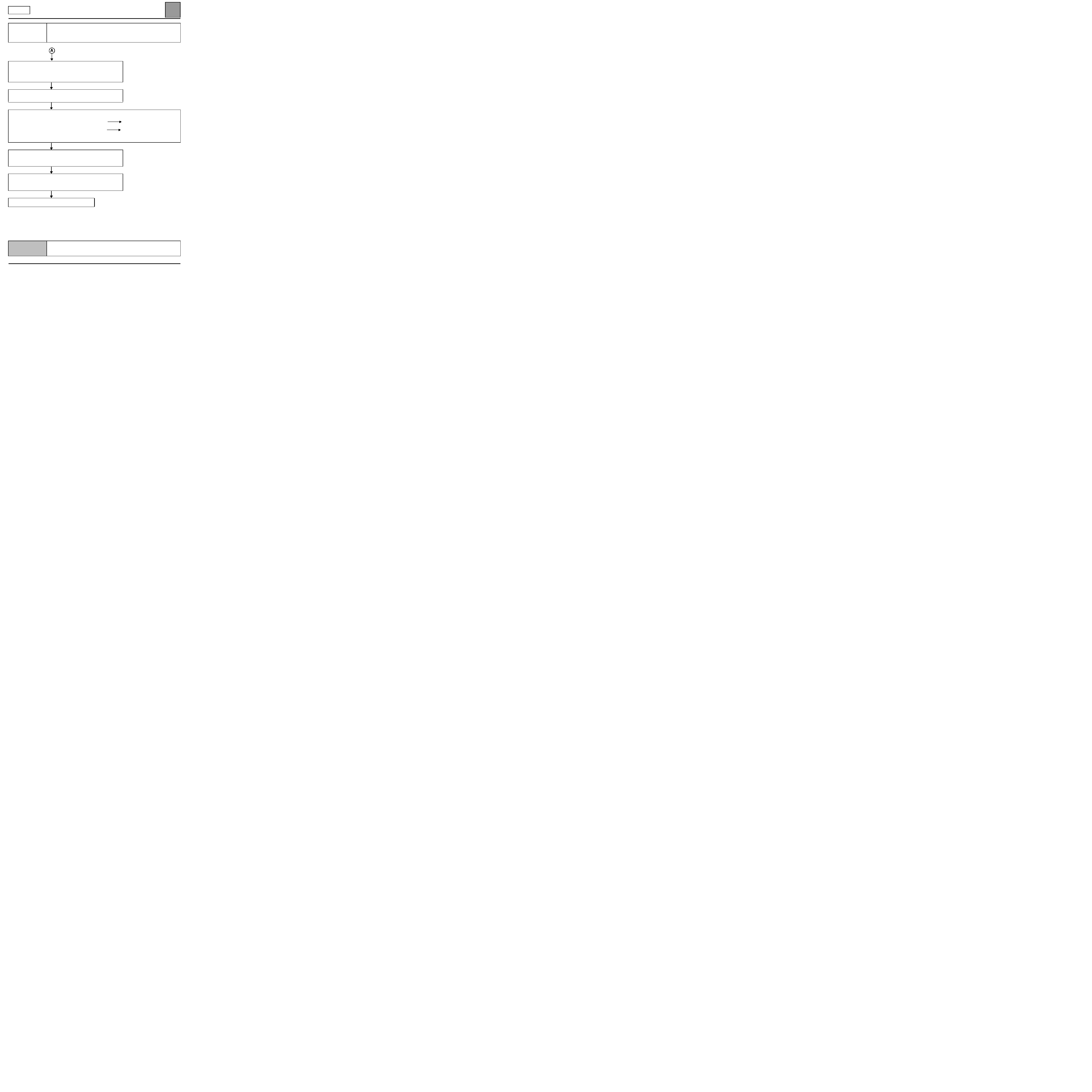
GENERAL APPROACH TO FAULT FINDING
– Use one of the diagnostic tools to identify the heating and ventilation system equipping the vehicle (to read the
computer family, the program number, the Vdiag, etc.).
– Locate the Fault finding documents corresponding to the system identified.
– Take note of information contained in the introductory sections.
DESCRIPTION OF THE FAULT FINDING PHASES
1 - CHECKING THE FAULTS
It is essential to start with this phase before any work is done on the vehicle.
– Read the faults stored in the computer memory and use the Fault interpretation section of the documents.
Reminder:
Each fault is interpreted for a particular type of storage (fault present, fault stored in memory, fault
present or stored). The checks defined for handling each fault are therefore only to be performed if the fault shown
by the diagnostic tool is interpreted in the document for its type of storage. The storage type should be considered
when using the diagnostic tool after the ignition has been switched off and switched back on.
If a fault is interpreted when it is declared stored, the conditions for application of the fault finding procedure appear
in the NOTES box. When these conditions are not satisfied, use the fault finding procedure to check the circuit of
the faulty part since the fault is no longer present on the vehicle. Follow the same procedure when a fault is declared
stored by the diagnostic tool but is only interpreted in the documentation for a present fault.
This document contains the special fault finding procedures applicable to all automatic climate control
computers fitted on the CLIO II.
To undertake fault finding on this system, it is essential to have the following items available:
– This section of the Workshop Repair Manual,
– The wiring diagram of the function on the vehicle concerned,
– The CLIP or NXR diagnostic tool,
– A control bornier.
CAREG X65 - 1.0
AUTOMATIC AIR CONDITIONING
Fault finding - Introduction
62
62-28
CAREG
VDIAG No.: 06
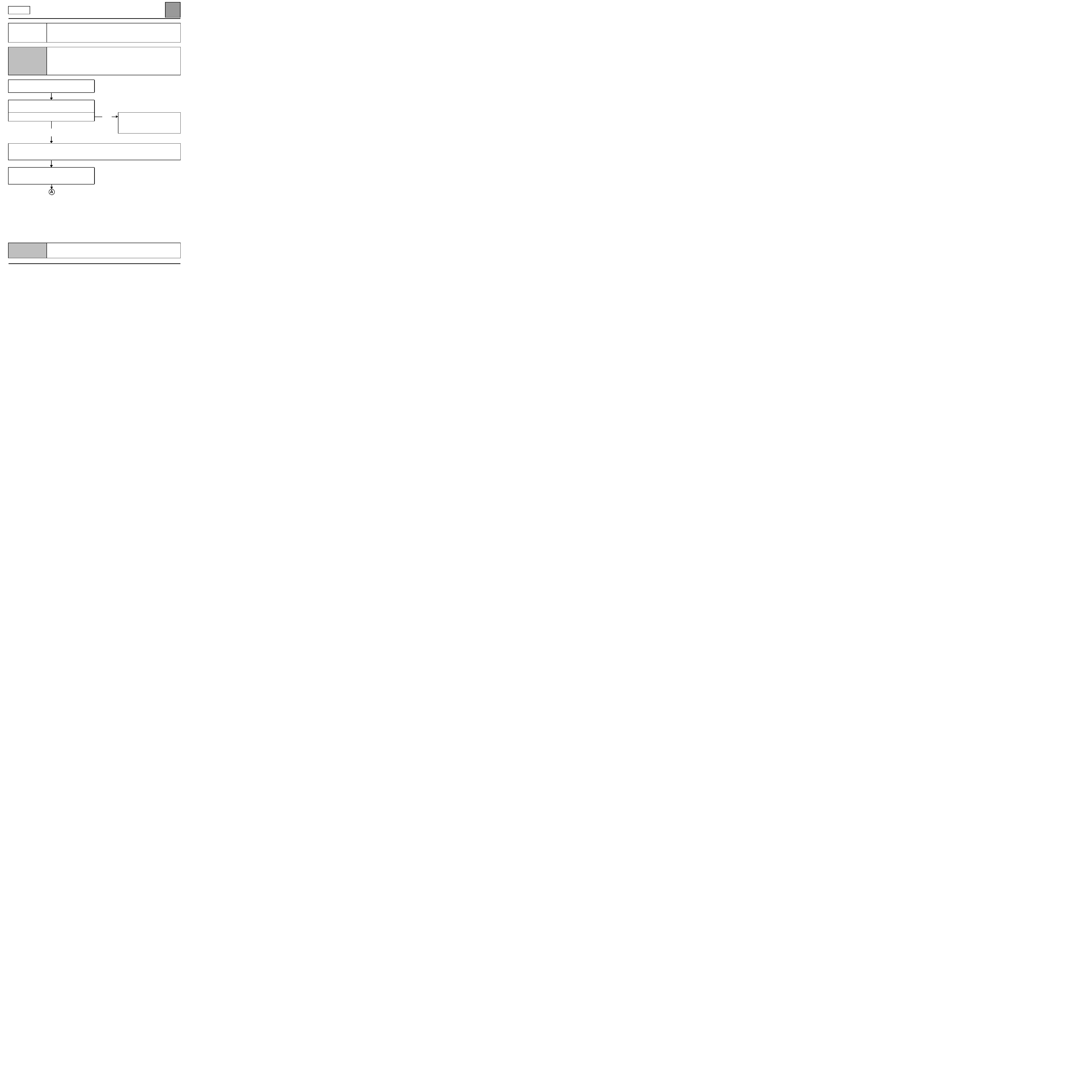
2 - CONFORMITY CHECK
The conformity check is designed to check the statuses and parameters which do not display any faults on the
diagnostic tool when they are outside the permitted tolerance values. This phase:
– Diagnoses faults that are not displayed which may correspond to a customer complaint.
– Checks the reliability of the heating and ventilation system and ensures that a fault will not reappear after repair.
This chapter gives the diagnostic procedures for statuses and parameters and the conditions for checking them. If a
status is not operating normally or a parameter is outside permitted tolerance values, you should consult the
corresponding diagnostic page.
3 - RECTIFYING THE CUSTOMER COMPLAINT
If the diagnostic tool check is correct, but the customer complaint is still present, the problem should be dealt with
according to the customer complaint.
This chapter includes fault finding charts, which give possible causes of the problem. These lines of research should
only be followed under the following circumstances:
– No fault observed on diagnostic tool.
– No anomaly detected during conformity check.
– The heating and ventilation system is not working correctly.
4 - SPECIAL FEATURES:
The heating and ventilation system cold loop is controlled by the injection computer
(compressor control,
control of the refrigerant pressure sensor and the engine cooling fan).
The climate control computer controls the compressor by means of a wire connection between the two computers.
If a fault is detected during the heating and ventilation diagnostic procedure but the compressor is not engaged, a
diagnostic procedure should be performed on the injection (refer to customer complaints).
– NO SPECIAL PROGRAMMING IS REQUIRED
(mixing and distribution motors programme their stops
automatically on ignition, after they are replaced or the battery has been disconnected).
NOTE:
when the distribution and mixing motors are at the minimum or maximum limit, they undergo dynamic
adjustment (programming travel). This programming operation causes a slight noise that may lead customers to
complain.
If the customer complains about the noise, explain that it is normal and necessary for automatic air conditioning
control in order to maintain optimum levels of performance.
– THE CLIMATE CONTROL COMPUTER HAS NO CONFIGURATION SERVICE.
5 - COMPUTER CONNECTOR DESIGNATIONS:
The automatic climate control computer has two connectors:
– a grey 30-track connector
connector A
– a red 15-track connector
connector B
CAREG X65 - 1.0
AUTOMATIC AIR CONDITIONING
Fault finding - Fault Interpretation
62
62-29
CAREG
VDIAG No.: 06
Fault finding - Fault Interpretation
DF001
PRESENT
OR
STORED
COMPUTER
NOTES
None.
The computer fault indicates an internal memory fault.
Try to erase the fault and run the heating and ventilation system.
If the fault reappears, check the connection and condition of the heating and
ventilation system control panel connectors.
Repair if necessary.
Connect the bornier in place of the computer and check the insulation, continuity
and absence of interference resistance
of the connections:
computer connector B track 15
+ before ignition
computer connector A track 7
earth
computer connector A track 3
+ accessories
computer connector A track 29
+ after ignition
Repair if necessary (see the vehicle diagrams).
If the fault persists, replace the climate control computer (control panel).
AFTER REPAIR
Clear the fault memory.
Deal with any other possible faults.
CAREG X65 - 1.0

AUTOMATIC AIR CONDITIONING
Fault finding - Fault Interpretation
62
62-30
CAREG
VDIAG No.: 06
DF007
PRESENT
OR
STORED
INTERIOR TEMPERATURE SENSOR CIRCUIT
CO : Open circuit
CC : Short circuit
NOTES
Special features:
The interior temperature sensor (linked to a small ventilation fan) is located above the
roof in the interior lighting unit.
Check the connection and status of the interior temperature sensor connector.
Replace the connector if necessary.
With the ignition on, check that the temperature sensor blower is in correct working
order
.
If not, check for the presence of +12 volts on track 1 of the temperature sensor
connector and an earth on track 3.
If the blower supply is correct and the blower is not working, replace the component:
sensors/blower
(the blower is not available separately).
Connect the bornier in place of the computer and check the insulation, continuity
and absence of interference resistance
of the connections:
computer connector A track 4
track 4
of the temperature
sensor
computer connector A track 21
track 6
of the temperature
sensor
Repair if necessary.
Check the resistance value of the sensor:
Track 4
and track 5 of the interior temperature sensor connector, replace the sensor
if the resistance is not approximately: 10 k
Ω
±
500
Ω
at 25
°
C
(for greater precision,
refer to the HELP section on sensor electrical specifications according to
temperature).
If the fault persists, replace the interior temperature sensor.
AFTER REPAIR
Clear the fault memory.
Deal with any other possible faults.
CAREG X65 - 1.0

AUTOMATIC AIR CONDITIONING
Fault finding - Fault Interpretation
62
62-31
CAREG
VDIAG No.: 06
DF010
PRESENT
OR
STORED
MIXING MOTOR CIRCUIT
NOTES
Conditions for applying the fault finding procedure to stored faults:
The fault is declared present when the air conditioning control panel is lit and the
temperature control activated (minimum or maximum temperature request).
Special features:
There is no specific programming operation for the mixing motor, however, after it has
been replaced, the motor needs to programme its limits (minimum and maximum).
This operation only occurs when the battery has been turned off. Therefore the battery
must be disconnected then reconnected
before restarting the ignition and starting
up the air conditioning.
Check the connection and status of the mixing motor connector.
Replace the connector if necessary.
Connect the bornier in place of the computer and check the insulation, continuity
and absence of interference resistance
of the connections:
computer connector B track 5
track 4
of the mixing motor
computer connector B track 6
track 1
of the mixing motor
computer connector B track 7
track 6
of the mixing motor
computer connector B track 8
track 3
of the mixing motor
Repair if necessary.
With the ignition on, check for the presence of 12 volts supply on track 2 of the
mixing motor connector.
Repair if necessary.
AFTER REPAIR
Follow the instructions to confirm repair.
Clear the fault memory.
Deal with any other possible faults.
CAREG X65 - 1.0
AUTOMATIC AIR CONDITIONING
Fault finding - Fault Interpretation
62
62-32
CAREG
VDIAG No.: 06
DF010
CONTINUED
With the connector disconnected, check the resistance value of the mixing motor by
measuring between:
track 2
and track 1 of the mixing motor connector,
track 2
and track 3 of the mixing motor connector,
track 2
and track 4 of the mixing motor connector,
track 2
and track 6 of the mixing motor connector,
The results on the four controls should be 84
Ω
±
4
Ω
at 20
°
C, if this is not the case,
replace the mixing motor.
Take the mixing motor apart,connect its connector and, using the diagnostic tool,
activate the controls: AC004 then AC005. The motor should switch from one
direction to the other.
If the connections matched when tested but the motor does not switch during the
commands: replace the mixing motor.
If the commands have been performed correctly, check that the mixing motor flap is
not blocked by trying to move the gears.
Repair if necessary.
If the fault persists, replace the mixing motor.
AFTER REPAIR
Follow the instructions to confirm repair.
Clear the fault memory.
Deal with any other possible faults.
CAREG X65 - 1.0
AUTOMATIC AIR CONDITIONING
Fault finding - Fault Interpretation
62
62-33
CAREG
VDIAG No.: 06
DF012
PRESENT
OR
STORED
DISTRIBUTION MOTOR CIRCUIT
NOTES
Conditions for carrying out a fault finding test on the fault stored:
The fault is declared present after: the air conditioning control panel is lit and the air
distribution control is operated (air vent, footwell, de-icing).
Special features:
There is no specific programming operation for the distribution motor, however, after it
has been replaced the motor needs to programme its limits (minimum and maximum).
This operation only occurs when the battery has been turned off. Therefore the battery
must be disconnected then reconnected
before restarting the ignition and starting
up the air conditioning.
Check the connection and status of the distribution motor connector.
Replace the connector if necessary.
Connect the bornier in place of the computer and check the insulation, continuity
and absence of interference resistance
of the connections:
computer connector B track 1
track 4
of the distribution motor
computer connector B track 2
track 3
of the distribution motor
computer connector B track 3
track 6
of the distribution motor
computer connector B track 4
track 1
of the distribution motor
Repair if necessary.
With the ignition on, check for the presence of 12 volts supply on track 2 of the
distribution motor connector.
Repair if necessary.
AFTER REPAIR
Follow the instructions to confirm repair.
Clear the fault memory.
Deal with any other possible faults.
CAREG X65 - 1.0

AUTOMATIC AIR CONDITIONING
Fault finding - Fault Interpretation
62
62-34
CAREG
VDIAG No.: 06
DF012
CONTINUED
With the connector disconnected, check the resistance value of the distribution
motor by measuring between:
track 2
and track 1 of the distribution motor connector,
track 2
and track 3 of the distribution motor connector,
track 2
and track 4 of the distribution motor connector,
track 2
and track 6 of the distribution motor connector,
The results on the four controls should be 84
Ω
±
4
Ω
at 20
°
C, if this is not the case,
replace the distribution motor.
Take the distribution motor apart, connect its connector and, using the diagnostic
tool, activate the commands: AC006 then AC007. The motor should switch from one
direction to the other.
If the connections tested earlier match but the motor does not switch during the
commands: replace the distribution motor.
If the commands have been performed correctly, check that the distribution motor
flap is not blocked by trying to move the gears.
Repair if necessary.
If the fault persists, replace the distribution motor.
AFTER REPAIR
Follow the instructions to confirm repair.
Clear the fault memory.
Deal with any other possible faults.
CAREG X65 - 1.0

AUTOMATIC AIR CONDITIONING
Fault finding - Fault Interpretation
62
62-35
CAREG
VDIAG No.: 06
DF021
PRESENT
OR
STORED
AIR RECIRCULATION MOTOR CIRCUIT
NOTES
Conditions for applying the fault finding procedure to stored faults:
The fault is declared present when the air conditioning control panel is lit and the air
recirculation control activated.
Take apart the right hand scuttle panel grille and check the connection and
condition
of the black 15-track connector and the connection and condition of the
3-track recirculation motor connector (next to the black 15-track connector).
Replace the connector(s) if necessary.
Connect the bornier in place of the computer and check the insulation, continuity
and absence of interference resistance
of the connections:
ECU connector A
black 15-track
yoke connector
3-track connector
of the recirculation motor
track 25
track 1
track C of the air
recirculation motor
track 26
track 2
track B
of the air
recirculation motor
Repair if necessary.
Check the resistance of the air recirculation motor across:
track C
and track B of the air recirculation motor connector and replace the motor
if the resistance is not approximately: 40
Ω
±
10
Ω
at 20
°
C.
Take apart the right hand scuttle panel and using the diagnostic tool, activate the
command: AC003.
It is possible to see the flap close by looking above the heating unit (it moves towards
the front of the vehicle). During the command, check that the recirculation motor flap
is closed without point of resistance or blockage.
Repair if necessary.
If the fault persists, replace the air recirculation motor.
AFTER REPAIR
Follow the instructions to confirm repair.
Clear the fault memory.
Deal with any other possible faults.
CAREG X65 - 1.0
AUTOMATIC AIR CONDITIONING
Fault finding - Fault Interpretation
62
62-36
CAREG
VDIAG No.: 06
DF096
PRESENT
OR
STORED
AIR BLOWER TEMPERATURE SENSOR CIRCUIT
CO : Open circuit
CC : Short circuit
NOTES
None.
Check the connection and condition of the delivery air temperature sensor
connector.
Replace the connector if necessary.
Check that the air blower temperature sensor has not slipped from its housing
(mounted by quarter turns).
Replace the sensor in its housing if necessary.
Connect the bornier in place of the computer and check the insulation, continuity
and absence of interference resistance
of the connections:
computer connector B track 13
track 1
of the temperature
sensor
computer connector B track 10
track 2
of the temperature
sensor
Repair if necessary.
Check the resistance value of the delivery air temperature sensor by measuring
across:
Track 1
and track 2 of the temperature sensor connector, replace the sensor if the
resistance is not approximately: 10 k
Ω
±
500
Ω
at 25
°
C
(for greater precision, refer
to the HELP section on sensor electrical specifications according to temperature).
If the fault persists, replace the delivery air temperature sensor.
AFTER REPAIR
Clear the fault memory.
Deal with any other possible faults.
CAREG X65 - 1.0
AUTOMATIC AIR CONDITIONING
Fault finding - Conformity check
62
CAREG
VDIAG No.: 06
Fault finding - Conformity check
NOTES
Only run a conformity check after a complete check with the diagnostic tool.
Test conditions:
engine off, ignition on, heating and ventilation off.
NOTE
: read the parameters when the vehicle is cold (in the morning) to check the
conformity of the temperature parameters (without thermometer). The three
temperatures should be about equal.
Order
Function
Parameter or status
Check or action
Display and notes
Fault finding
1
Computer
voltage supply
ET001:
+ 12V accessories
ACTIVE
In the event of a
problem occurring with
the statuses and the
parameter, check the
insulation, continuity
and absence of
resistance
interference
of the
computer earths and
supplies (see
electronic diagrams).
If the problem persists,
carry out a fault
finding test on the
charging circuit
.
ET002:
+ 12V lights
INACTIVE
(ACTIVE when the
side lights are
activated)
PR014:
computer supply
voltage
10 V < x < 12.5 V.
2
Interior
temperature.
PR001:
interior temperature
X = interior
temperature
±
5
°
C
(substitution value:
128
°
)
In the event of a
problem occurring
carry out a fault
finding test
on fault:
DF007
interior
temperature sensor
circuit.
3
External
temperature.
PR002:
external temperature
X = external
temperature
±
5
°
C
(substitution value:
128
°
)
In the event of a
problem, consult the
fault finding
procedure for
parameter PR002
4
Delivery air
temperature.
PR115:
delivery air
temperature.
X = delivery air
temperature
±
5
°
C
(the temperature
varies depending on
whether the mixing
motor is open)
(substitution value:
128
°
)
In the event of a
problem perform the
fault finding
procedure
: DF096
delivery air
temperature sensor
circuit.
CAREG X65 - 1.0
62-37
AUTOMATIC AIR CONDITIONING
Fault finding - Conformity check
62
62-38
CAREG
VDIAG No.: 06
NOTES
Only check the conformity after a complete check with the diagnostic tool.
Test conditions:
engine off, ignition on, heating and ventilation system off.
Order
Function
Parameter or status
Check or action
Display and notes
Fault finding
5
Passenger
compartment
blower
assembly
PR116:
passenger
compartment blower
assembly speed
0%
at minimum speed.
100%
at maximum
speed.
For greater precision,
refer to fault finding
parameter PR116.
6
Position of
distribution and
mixing flaps.
PR011:
position of
distribution flap
0%
air vents
at 100%: de-icing
For greater precision,
refer to fault finding
parameter PR011.
In the event of a
problem occurring
carry out a fault
finding test
on fault:
DF012
distribution
motor circuit.
PR012:
Position of mixing
flap
0%
maximum cold
to 100% maximum heat
In the event of a
problem occurring
carry out a fault
finding test
on fault:
DF010
mixing motor
circuit.
7
Air recirculation.
ET021:
air recirculation
motor command
STATUS 1
recirculation
motor: recirculation
STATUS 2
recirculation
motor: external air
In the event of a
problem occurring
carry out a fault
finding test
on fault:
DF021
air
recirculation motor
circuit.
ET079:
recirculation request
YES
or NO
according to the request
8
Air conditioning
request
ET078:
air conditioning
request
NO
None.
CAREG X65 - 1.0
AUTOMATIC AIR CONDITIONING
Fault finding - Conformity check
62
62-39
CAREG
VDIAG No.: 06
NOTES
Only check the conformity after a complete check with the diagnostic tool.
Running the actuator commands is a way of reporting faults when stored, or of
checking the reliability of the actuators.
Test conditions:
engine off, ignition on, heating and ventilation off.
Order
Function
Parameter or status
Check or action
Display and notes
Fault finding
Command window
9
Recirculation
AC002:
Recirculation motor:
external air
The recirculation flap
should be in the external
air position.
In the event of a
problem occurring
carry out a fault
finding test
: DF021
air recirculation motor
circuit.
AC003:
Recirculation motor:
recirculation
The recirculation flap
should be in the
recirculation position.
10
Mixing.
AC004:
Mixing motor:
maximum cold
The recirculation flap
should be in the
maximum cold position.
In the event of a
problem occurring
carry out a fault
finding test
: DF010
mixing motor circuit.
AC005:
Mixing motor:
maximum heat
The recirculation flap
should be in the hot
position.
11
Air distribution.
AC006:
Distribution motor:
air vents
The distribution flap
should be in air vent
mode.
In the event of a
problem occurring
carry out a fault
finding test
: DF012
distribution motor
circuit.
AC007:
Distribution motor:
de-icing
The distribution flap
should be in de-icing
mode.
CAREG X65 - 1.0
AUTOMATIC AIR CONDITIONING
Fault finding - Conformity check
62
62-40
CAREG
VDIAG No.: 06
NOTES
Only check the conformity after a complete check with the diagnostic tool.
Running the actuator commands is a way of reporting faults when stored, or of
checking the reliability of the actuators.
Test conditions:
engine off, ignition on, heating and ventilation off.
Order
Function
Parameter or status
Check or action
Display and notes
Fault finding
Command window
12
Compressor
control.
AC021:
Compressor clutch
The compressor clutch
should cut in.
Special features: since
the compressor clutch
command is
controlled by the
injection computer, it
is necessary to start
the engine before
starting the command
(injection can only be
authorised when the
engine is running).
If there is a problem,
refer to the chart
No. 8
, or perform an
injection fault finding
procedure.
13
Indicators.
AC026:
Control panel
indicators
The control panel
indicators should light
up.
If there is a problem,
refer to the chart
No. 12
.
14
Passenger
compartment
ventilation.
AC001:
Passenger
compartment blower
assembly
It should be possible to
hear the passenger
compartment blower
running.
If there is a problem,
refer to the chart
No. 5
.
CAREG X65 - 1.0
AUTOMATIC AIR CONDITIONING
Fault finding - Conformity check
62
62-41
CAREG
VDIAG No.: 06
NOTES
Only check the conformity after a complete check with the diagnostic tool.
Test conditions
: engine at idle speed, heating and ventilation on.
Order
Function
Parameter or status
Check or action
Display and notes
Fault finding
1
Computer
voltage supply
ET001:
+ 12V accessories
ACTIVE
In the event of a
problem occurring with
the statuses and the
parameter, check the
insulation, continuity
and resistance
interference
of the
computer earths and
supplies (see
electronic diagrams).
If the problem persists,
carry out a fault
finding test on the
charging circuit
.
ET002:
+ 12V lights
ACTIVE
PR014:
computer supply
voltage
12.5 V < x < 14.4 V.
2
Heating and
ventilation
system request
ET078:
heating and ventilation
system request
YES
None.
3
Passenger
compartment
blower
assembly
PR116:
passenger
compartment blower
assembly speed
0%
at minimum
speed.
100%
at maximum
speed.
For greater precision,
refer to fault finding
parameter PR116.
4
Position of
distribution and
mixing flaps.
PR011:
position of distribution
flap
0%
: air vents
to 100%: de-icing
In the event of a
problem occurring
carry out a fault
finding test
on fault:
DF012
distribution
motor circuit.
PR012:
position of mixing flap
0%
maximum cold
to 100 % maximum
heat
In the event of a
problem occurring
carry out a fault
finding test
: DF010
mixing motor circuit.
CAREG X65 - 1.0
AUTOMATIC AIR CONDITIONING
Fault finding - Conformity check
62
62-42
CAREG
VDIAG No.: 06
NOTES
Only check the conformity after a complete check with the diagnostic tool.
Test conditions
: engine at idle speed, heating and ventilation on.
NOTE: it is difficult to test the validity of temperature information when the
heating and ventilation is operating (particularly the delivery air temperature
which varies more rapidly than the other two). It is preferable to check the
validity of temperature information when the heating and ventilation is off (refer
to the NOTE on checking conformity, when the heating and ventilation is off).
Order
Function
Parameter or status
Check or action
Display and notes
Fault finding
5
Air recirculation.
ET021:
air recirculation
motor command
STATUS 1
recirculation
motor: recirculation
STATUS 2
recirculation
motor: external air
In the event of a
problem occurring
carry out a fault
finding test
on fault:
DF021
air
recirculation motor
circuit.
ET079:
recirculation request
YES
or NO
depending on the
request
6
Temperatures.
PR001:
interior temperature
X = external
temperature
±
5˚C
(substitution value:
128
°
C)
In the event of a
problem, perform the
fault finding
procedure
:
DF007
interior
temperature sensor
circuit.
PR002:
external temperature
X = external
temperature
±
5˚C
(substitution value:
128
°
C)
In the event of a
problem, consult the
fault finding
procedure for status
PR002
PR115:
delivery air
temperature.
X = delivery air
temperature
±
5
°
C
(the temperature varies
depending on whether
the mixing motor is
open)
(substitution value:
128
°
C)
In the event of a
problem, perform the
fault finding
procedure
:
DF096
delivery air
temperature sensor
unit.
CAREG X65 - 1.0
AUTOMATIC AIR CONDITIONING
Fault finding - Parameter interpretation
62
62-43
CAREG
VDIAG No.: 06
Fault finding - Parameter interpretation
Vehicles fitted with a central communication unit:
PR002
EXTERNAL TEMPERATURE
NOTES
Special note
:
The external temperature sensor is located in the right-hand side rear-view mirror.
Look at the temperature shown on the multifunction display. Is it consistent?
If the temperature shown on the multifunction display is consistent:
connect the bornier in place of the
climate control computer and check the insulation, continuity and resistance interference of the
connection:
climate control computer central communication unit
connector A track 28
track 21
of connector C
Repair if necessary.
If the connection matched when tested but the fault persists, measure the voltage of the temperature signal
between track 28 (connector A) of the climate control computer and the earth:
– Between 5 and 7 volts should be measured with the voltmeter set to AC voltage measuring.
– A square wave signal should appear on the oscilloscope (top status at 12 volts).
If the central communication unit emits no voltage and the display shows a consistent temperature: replace
the central communication unit.
If the central communication unit emits voltage and the display shows a consistent temperature: replace the
climate control computer.
If the temperature shown on the multifunction display is not consistent:
ensure that the display is not
faulty by running its fault finding procedure (refer to the multifunction display technical note).
AFTER REPAIR
Restart the conformity check from the beginning.
CAREG X65 - 1.0

AUTOMATIC AIR CONDITIONING
Fault finding - Parameter interpretation
62
62-44
CAREG
VDIAG No.: 06
PR002
CONTINUED 1
Using the diagnostic tool, test the multiplex network to check the conformity of the connection between the
central communication unit and the display. If the connection is faulty, connect the bornier in place of the
central communication unit computer and check the insulation, continuity and resistance interference of
the connections:
multifunction display central communication unit
connector B track 15
track 4
of connector C
connector B track 14
track 3
of connector C
connector B track 12
track 7
of connector C
Repair if necessary.
If the connections are correct, perform a fault finding procedure on the central communication unit to
check that the external temperature sensor is in correct working order (refer to the central communication unit
fault finding note).
Replace the external temperature sensor if necessary.
If the external temperature sensor is not faulty, connect the bornier in place of the central communication unit
computer and check the insulation, continuity and resistance interference of the connections:
central communication unit C track 16
track 4
of the external temperature sensor.
central communication unit C track 17
track 3
of the external temperature sensor.
Repair if necessary.
If the above tests have not solved the problem, connect the bornier in place of the climate control computer
and check the insulation, continuity and resistance interference of the connections:
climate control computer central communication unit
connector A track 28
track 21
of connector C
Repair if necessary.
AFTER REPAIR
Restart the conformity check from the beginning.
CAREG X65 - 1.0
AUTOMATIC AIR CONDITIONING
Fault finding - Parameter interpretation
62
62-45
CAREG
VDIAG No.: 06
Vehicles not fitted with a central communication unit:
PR002
CONTINUED 2
If the connections matched when tested but the fault persists, measure the voltage of the temperature
signal
between track 28 (connector A) of the climate control computer and the earth:
– Between 5 and 7 volts should be measured with the voltmeter set to AC voltage measuring.
– A square wave signal should appear on the oscilloscope (top status at 12 volts).
If the central communication unit emits no voltage but the display shows a consistent temperature: replace
the central communication unit.
If the central communication unit emits voltage and the display shows a consistent temperature: replace the
climate control computer.
Look at the temperature shown on the multifunction display. Is it consistent?
If the temperature shown on the multifunction display is consistent
, connect the bornier in place of the
multifunction display and check the insulation, continuity and resistance interference of the connections:
Multifunction display connector B track 2
track 3
of the external temperature sensor.
Multifunction display connector B track 1
track 4
of the external temperature sensor.
Repair if necessary.
If the connections are correct, perform a multifunction display fault finding procedure to ensure that it is
not faulty and that the external temperature sensor is in correct working order (refer to the multifunction display
fault finding note).
If the connections matched when tested and the external temperature sensor is not faulty but the fault persists,
connect the bornier in place of the climate control computer and check the insulation, continuity and
resistance interference
of the connection:
climate control computer multifunction display
connector A track 28
track 10
of connector B
Repair if necessary.
AFTER REPAIR
Restart the conformity check from the beginning.
CAREG X65 - 1.0
AUTOMATIC AIR CONDITIONING
Fault finding - Parameter interpretation
62
62-46
CAREG
VDIAG No.: 06
PR002
CONTINUED 3
If the connections matched when tested but the fault persists, measure the voltage of the temperature
signal
between track 28 (connector A) of the climate control computer and the earth:
– Between 5 and 7 volts should be measured with the voltmeter set to AC voltage measuring.
– A square wave signal should appear on the oscilloscope (top status at 12 volts).
If the multifunction display emits no voltage but it shows a consistent temperature: replace the multifunction
display.
If the multifunction display emits voltage and it shows a consistent temperature: replace the climate control
computer.
If the temperature shown on the multifunction display is consistent
: connect the bornier in place of the
climate control computer and check the l insulation, continuity and resistance interference of the
connection:
climate control computer multifunction display
connector A track 28
track 10
of connector B
Repair if necessary.
If the connection matched when tested, measure the voltage of the temperature signal between track 28
(connector A) of the climate control computer and the earth:
– Between 5 and 7 volts should be measured with the voltmeter set to AC voltage measuring.
– A square wave signal should appear on the oscilloscope (high status at 12 volts).
If the multifunction display emits no voltage but it shows a consistent temperature: replace the multifunction
display.
If the multifunction display emits voltage and it shows a consistent temperature: replace the climate control
computer.
AFTER REPAIR
Restart the conformity check from the beginning.
CAREG X65 - 1.0

AUTOMATIC AIR CONDITIONING
Fault finding - Parameter interpretation
62
62-47
CAREG
VDIAG No.: 06
Controlled values for engine halted and engine running with heating and ventilation in manual mode
(tolerance
±
5%).
PR011
POSITION OF DISTRIBUTION FLAP
NOTES
The values listed are an example only, (they vary depending on the position of the flap
control).
Air distribution request
Position of distribution flap
Air vents
0%
Air vent + footwells
14%
Footwell ventilation
50 %
Footwells + demisting
82%
Demisting
100 %
AFTER REPAIR
Restart the conformity check from the beginning.
CAREG X65 - 1.0
AUTOMATIC AIR CONDITIONING
Fault finding - Parameter interpretation
62
62-48
CAREG
VDIAG No.: 06
Controlled values for engine halted and engine running (tolerance
±
5%).
PR116
PASSENGER COMPARTMENT BLOWER ASSEMBLY SPEED
NOTES
The values listed below are examples only.
Passenger compartment
blower assembly speed
specification
SPEED 0 SPEED 1 SPEED 2 SPEED 3 SPEED 4 SPEED 5 SPEED 6SPEED 7 SPEED 8
Passenger compartment
blower assembly speed
display.
0%
20 %
30%
40 %
50 %
62%
74%
85%
92%
AFTER REPAIR
Restart the conformity check from the beginning.
CAREG X65 - 1.0
AUTOMATIC AIR CONDITIONING
Fault finding - Help
62
62-49
CAREG
VDIAG No.: 06
Fault finding - Help
MEASURING THE CONTROL VOLTAGE OF THE
PASSENGER COMPARTMENT BLOWER ASSEMBLY POWER MODULE
There are two ways to measure the control voltage of the passenger compartment blower assembly power module:
1 / Measuring on a multimeter
(in Voltmeter position):
With the power module connector connected, measure across track 2 of the module and the earth.
At speed 0 the voltage measured should be equal to the battery voltage.
At maximum speed (8) the voltage should be negligible (
±
0.5 volts).
For the 7 speeds in between the voltage varies between 0 and 12 volts.
Examples of measurements taken
with the Voltmeter with the engine at
idling speed (for information only):
speed 0
13.94 volts
speed 1
11.36 volts
speed 2
10.17 volts
speed 3
8.93 Volts
speed 4
7.69 Volts
speed 5
6.34 volts
speed 6
5.13 volts
speed 7
3.80 volts
speed 8
0.14 volts
2 / Measuring using an oscilloscope
(Optima 5800, Clip technique or NXR):
The blower assembly power module is controlled by a modulated control voltage (PWM).
This control voltage is always 12 volts, the control signal (square wave signal) varies: the range and frequency do
not move, the high status (12 Volts) varies in relation to the low status (0 Volts).
To measure,connect the oscilloscope earth lead to the battery earth and the oscilloscope measuring lead to track 2
of the power module (connected module connector). Adjust the time base on the oscilloscope to 500
µ
/s
divisions
with a gauge of 5-Volt divisions.
The signals obtained should be: a straight line at 14 Volts for speed 0, a straight line at 0 Volts for speed 8.
Example of measurements for the seven speeds in between (for information only):
Blower
assembly
speed
duration of
high status
duration of
low status
speed 1
450
µ
/s
50
µ
/s
speed 2
400
µ
/s
100
µ
/s
speed 3
350
µ
/s
150
µ
/s
speed 4
300
µ
/s
200
µ
/s
Blower
assembly
speed
duration of
high status
duration of
low status
speed 5
250
µ
/s
250
µ
/s
speed 6
200
µ
/s
300
µ
/s
speed 7
150
µ
/s
350
µ
/s
CAREG X65 - 1.0
AUTOMATIC AIR CONDITIONING
Fault finding - Help
62
62-50
CAREG
VDIAG No.: 06
Fault finding - Help
Electrical specifications of the temperature sensors according to temperature (tolerance:
±
5 %).
Inside temperature sensor
Delivery air temperature sensor
Temperatures
Sensor resistance
- 30
°
C
175200
Ω
- 25
°
C
129300
Ω
- 20
°
C
96360
Ω
- 15
°
C
72500
Ω
- 10
°
C
55050
Ω
- 5
°
C
42160
Ω
0
°
C
32560
Ω
5
°
C
25340
Ω
10
°
C
19870
Ω
15
°
C
15700
Ω
20
°
C
12490
Ω
25
°
C
10000
Ω
30
°
C
8059
Ω
35
°
C
6535
Ω
40
°
C
5330
Ω
45
°
C
4372
Ω
50
°
C
3606
Ω
55
°
C
2989
Ω
60
°
C
2490
Ω
Temperatures
Sensor resistance
- 20
°
C
96358
Ω
- 15
°
C
72500
Ω
- 10
°
C
55046
Ω
- 5
°
C
42157
Ω
0
°
C
32554
Ω
5
°
C
25339
Ω
10
°
C
19872
Ω
15
°
C
15698
Ω
20
°
C
12487
Ω
25
°
C
10000
Ω
30
°
C
8059
Ω
35
°
C
6534
Ω
40
°
C
5329
Ω
45
°
C
4371
Ω
50
°
C
3605
Ω
55
°
C
2988
Ω
60
°
C
2490
Ω
AUTOMATIC AIR CONDITIONING
Fault finding - Customer complaints
62
62-51
CAREG
VDIAG No.: 06
Fault finding - Customer complaints
NOTES
Only refer to this customer complaint after a complete check using the diagnostic tool
FAULTY AIR DISTRIBUTION
FAULTY AIR DISTRIBUTION
CHART 1
AIR FLOW PROBLEM
CHART 2
INEFFICIENT WINDSCREEN DEMISTING
CHART 3
POOR VENTILATION PERFORMANCE
CHART 4
NO PASSENGER COMPARTMENT VENTILATION
CHART 5
FAULTY HEATING
NO HEATING OR INADEQUATE HEATING
CHART 6
TOO HOT
CHART 7
NO COLD AIR
CHART 8
AIR TOO COLD
CHART 9
ODOUR PROBLEM IN PASSENGER COMPARTMENT
UNPLEASANT ODOURS IN PASSENGER COMPARTMENT
CHART 10
WATER IN PASSENGER COMPARTMENT
WATER IS PRESENT IN PASSENGER COMPARTMENT
CHART 11
FAULTY CONTROL PANEL
CONTROL PANEL LIGHTING FAILURE
CHART 12
COMPRESSOR NOISES
NOISY COMPRESSOR
CHART 13
CAREG X65 - 1.0

AUTOMATIC AIR CONDITIONING
Fault finding - Fault finding charts
62
CAREG
VDIAG No.: 06
Fault finding - Fault finding charts
CHART 1
FAULTY AIR DISTRIBUTION
NOTES
Only refer to this customer complaint after a complete check using the diagnostic
tool
Special notes:
Switching on the air distribution or ventilation functions automatically switches off the
heating and ventilation automatic mode.
Check that the air circuit (particle filter, scuttle panel grille, air vents etc.) is not blocked.
Repair, clean or replace the particle filter if necessary.
Ensure that the blower unit is properly airtight.
Repair if necessary.
Set the passenger compartment fan to maximum speed
and the temperature control to maximum heator maximum
cold and move the air distribution control.
Check that the air outlet corresponds to the selection.
Is the customer complaint confirmed?
YES
Look at the distribution motor under the glove
compartment and check visually that moving the control
moves the distribution flap.
Does it move?
YES
End of fault finding.
Take apart the distribution motor and move the flap by turning its gear
system. Check that the flap is not seized up .
Replace the heating assembly if necessary.
NO
NO
YES
The air distribution is correct.
If necessary, explain how the
system works to the customer
again.
Take apart the distribution
motor and the connector from
the connected motor, activate
the air vent command then the
de-icing command on the
control panel. The motor should
change from its minimum
position to the maximum(PR011
on the diagnostic tool: 0% at
100
%).
Does the distribution motor
operate?
NO
Replace the distribution
motor.
AFTER REPAIR
Check that the system is operating correctly.
CAREG X65 - 1.0
62-52

AUTOMATIC AIR CONDITIONING
Fault finding - Fault finding charts
62
62-53
CAREG
VDIAG No.: 06
CHART 2
AIR FLOW PROBLEM
NOTES
Only refer to this customer complaint after a complete check using the diagnostic
tool
Check that the customer knows how to work the heating and ventilation properly.
Does the passenger compartment blower operate?
YES
Check that the air circuit (particle filter, scuttle panel grille, air vents and extractors etc.) is not blocked.
Check that the blower casing is in good condition (by looking to the left of the particle filter housing).
Repair, clean or replace the particle filter if necessary.
Ensure that the blower unit is correctly sealed.
Repair if necessary.
Using the diagnostic tool, check that the recirculation flap is not closed in recirculation position with status
check: ET021 recirculation motor control.
Does the problem disappear when the air distribution is
changed?
NO
Run a conformity check as the problem may arise from a faulty signal from one of the temperature sensors
(internal, external and delivery air).
Check that the interior air temperature micro-turbine is in correct working order (if it is faulty it may make the
measurement incorrect).
Replace any faulty components.
NO
YES
To repair, see CHART 5
Ensure that all the air vents are open.
If the fault persists, see CHART 1.
AFTER REPAIR
Check that the system is operating correctly.
CAREG X65 - 1.0
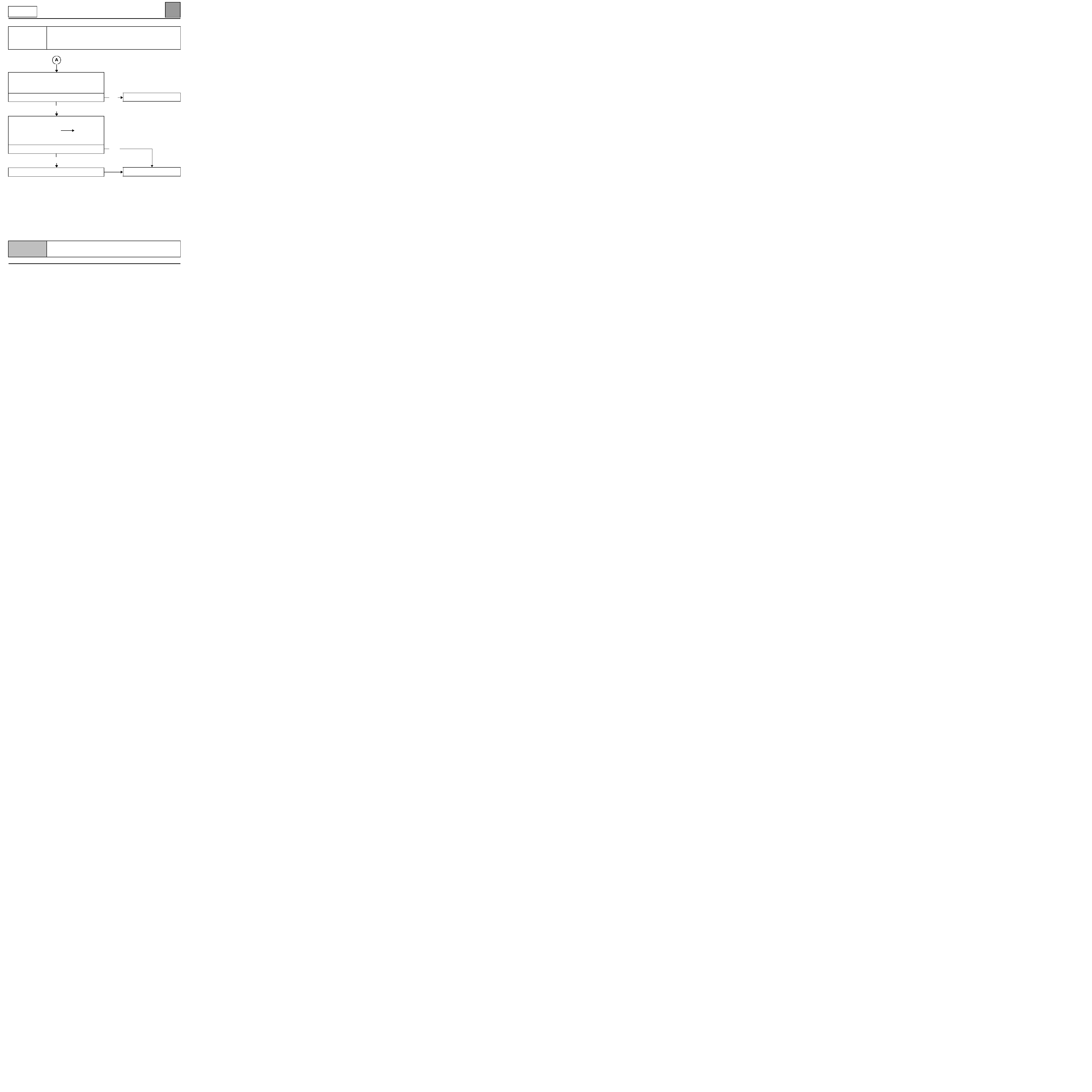
AUTOMATIC AIR CONDITIONING
Fault finding - Fault finding charts
62
62-54
CAREG
VDIAG No.: 06
CHART 2
CONTINUED
Check that the PWM (modulated control specifications)
for the passenger compartment blower assembly power
unit vary between track A2 of the unit and the earth (see
HELP for the measurement).
Does the voltage vary correctly?
NO
Check the continuity and interference resistance of the
connection:
computer connector B track 11
track A2
of the
unit
Repair if necessary.
Is the fault still present?
YES
Replace the control panel.
YES
NO
Replace
the power module.
End of fault finding.
AFTER REPAIR
Check that the system is operating correctly.
CAREG X65 - 1.0

AUTOMATIC AIR CONDITIONING
Fault finding - Fault finding charts
62
62-55
CAREG
VDIAG No.: 06
CHART 3
INEFFICIENT WINDSCREEN DEMISTING
NOTES
Only refer to this customer complaint after a complete check using the diagnostic
tool
Special notes:
Check that the inside of the windows are not dirty, as this lowers the efficiency of the
demister.
Check that the distribution motor is in de-icing position by viewing the PR011 parameter using the diagnostic
tool in distribution flap position, it should be at 100%.
Check that the air extractors are not blocked.
Repair if necessary.
Is the fault still present?
YES
Using the diagnostic tool, check that the air recirculation flap is in the external air position by checking status
ET021
air recirculation motor command.
Repair if necessary.
Is the fault still present?
YES
Run a conformity check as the problem may arise from
a faulty signal from the temperature sensors (internal,
external and delivery air). Check that the interior air
temperature micro-turbine is in correct working order (if it
is faulty it may make the measurement incorrect).
Replace any faulty components.
Is the fault still present?
YES
NO
NO
End of fault finding.
NO
End of fault finding.
AFTER REPAIR
Check that the system is operating correctly.
CAREG X65 - 1.0
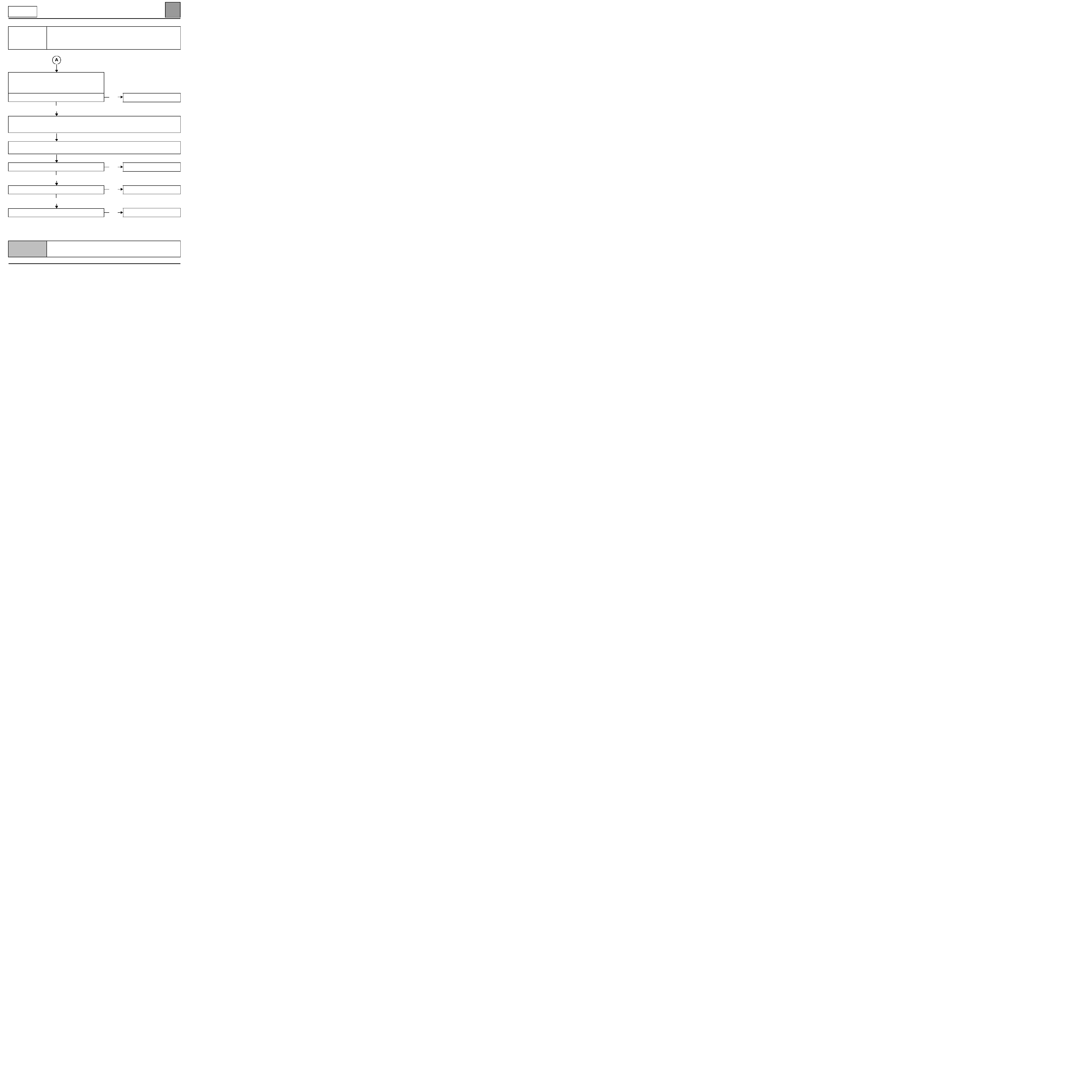
AUTOMATIC AIR CONDITIONING
Fault finding - Fault finding charts
62
62-56
CAREG
VDIAG No.: 06
CHART 3
CONTINUED
Check that there are no water leaks into the passenger
compartment which would significantly increase the
humidity and reduce the effectiveness of the demisting.
Repair if necessary (see CHART 11).
Is the fault still present?
YES
Check that the compressor is in correct working order by using command: AC021 compressor clutch or by
switching on the heating and ventilation.
Repair if necessary.
Check that the water evaporator outlet is not blocked.
Repair if necessary.
Is it an air distribution problem?
NO
Is it an air flow problem?
NO
Is it a heater performance problem?
NO
YES
YES
YES
See CHART 1
See CHART 2
See CHART 6
End of fault finding.
AFTER REPAIR
Check that the system is operating correctly.
CAREG X65 - 1.0
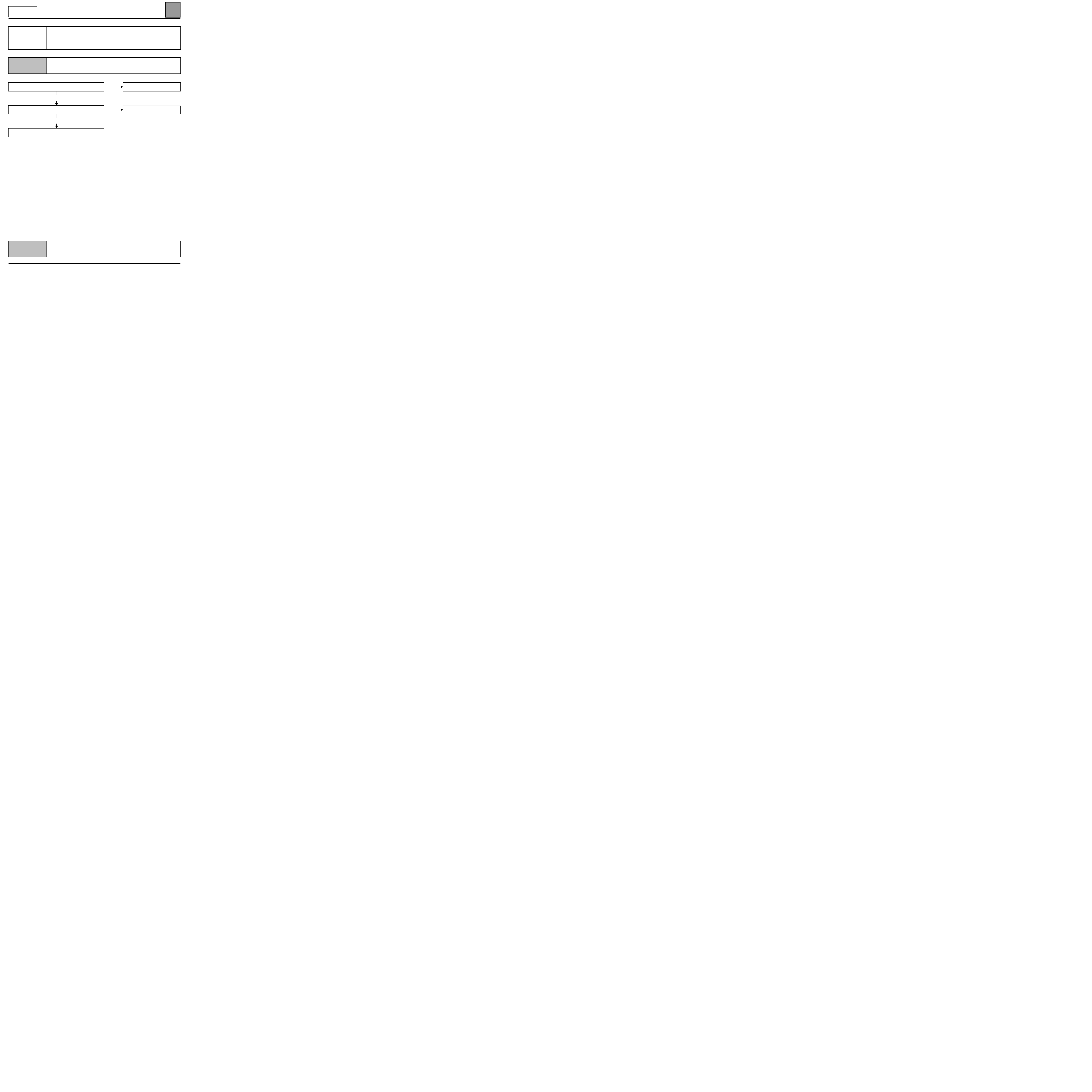
AUTOMATIC AIR CONDITIONING
Fault finding - Fault finding charts
62
62-57
CAREG
VDIAG No.: 06
CHART 4
POOR VENTILATION PERFORMANCE
NOTES
Only refer to this customer complaint after a complete check using the diagnostic tool
Is the air flow correct?
YES
Is the air distribution correct?
YES
End of fault finding.
NO
NO
See CHART 2
See CHART 1
AFTER REPAIR
Check that the system is operating correctly.
CAREG X65 - 1.0
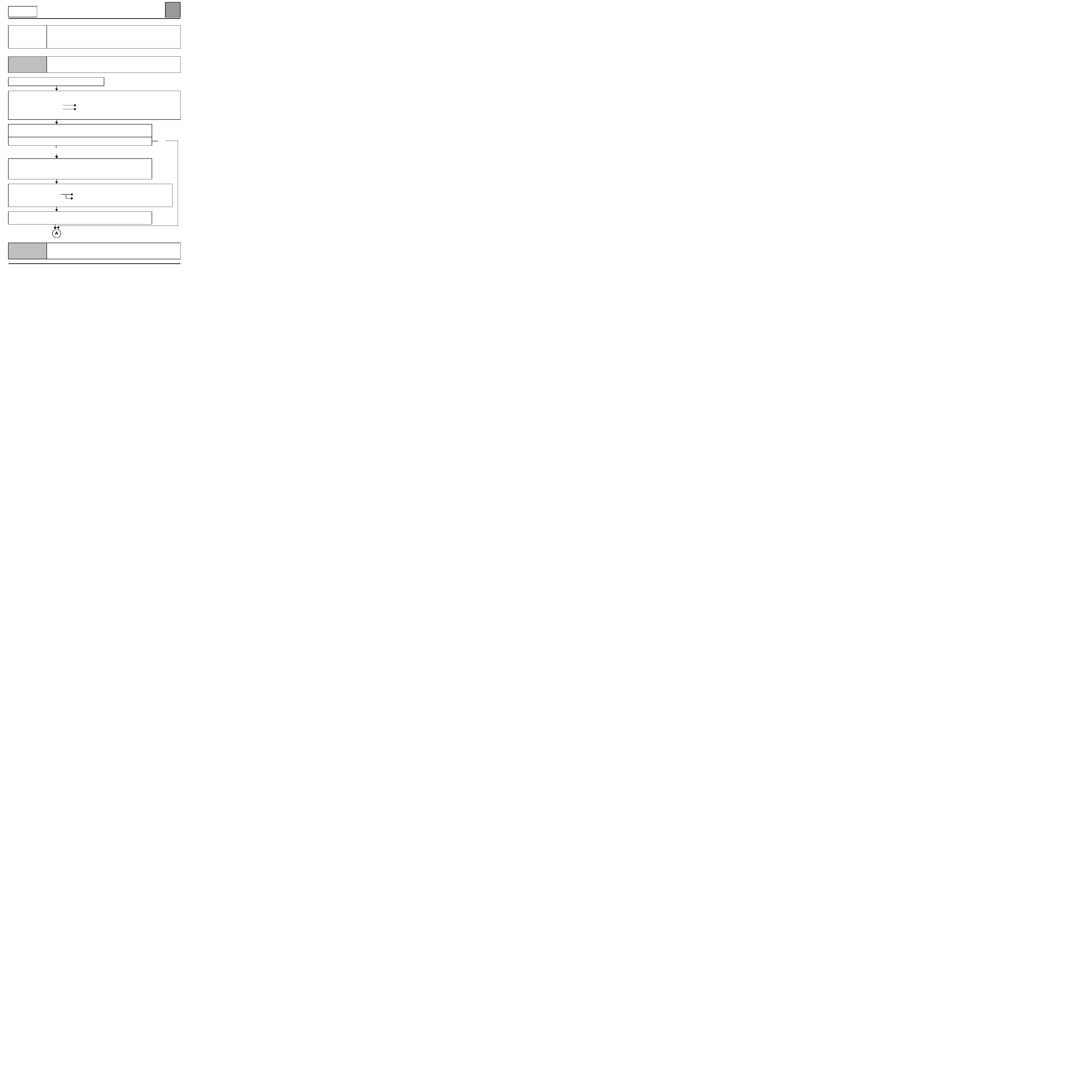
AUTOMATIC AIR CONDITIONING
Fault finding - Fault finding charts
62
62-58
CAREG
VDIAG No.: 06
CHART 5
NO PASSENGER COMPARTMENT VENTILATION
NOTES
Only refer to this customer complaint after a complete check using the diagnostic tool
Check that the fuses are in good condition.
Connect the bornier in place of the computer and check the insulation, continuity and absence of
interference resistance
of the connections:
computer connector B track 11
track 2
of the passenger compartment blower power module
computer connector A track 16
track 3
of the passenger compartment power module
Repair if necessary.
With the ignition on, check that there are +12 volts on track 4 of the power module and on
track 1
of the passenger compartment ventilation motor.
Is there a supply?
NO
Check for the presence of +12 volts before ignition on track 30, an earth on track 85 and
+ 12 volts after ignition
on track 86 of the cold air blower relay (yellow relay on an
individual relay gate in the engine compartment fuse box).
Repair if necessary.
Check the insulation, continuity and absence of interference resistance of the connections:
cold air delivery relay track 87
track 4
of the passenger compartment blower power modul
track 1
of the passenger compartment blower motor
Repair if necessary.
If there is still no 12 volt supply on track 4 of the power module and track 1 of the
passenger compartment blower motor: replaces the cold air delivery relay.
YES
AFTER REPAIR
Check that the system is operating correctly.
CAREG X65 - 1.0

AUTOMATIC AIR CONDITIONING
Fault finding - Fault finding charts
62
62-59
CAREG
VDIAG No.: 06
CHART 5
CONTINUED
Check for the presence of an earth on track 5 of the passenger compartment blower power module.
Repair if necessary.
Check the insulation, continuity and absence of interference resistance of the connection:
power module track 1
track 2
of the passenger compartment blower motor
Repair if necessary.
Take apart the particle filter (under the right hand scuttle panel grille) and check that the passenger
compartment blower casing has not broken or slipped out of position
Replace the passenger compartment blower if necessary.
Disconnect the connector from the power module (under the right hand scuttle panel grille) and, with the
ignition on, shunt tracks 1 and 5. The blower should run at maximum speed.
If the blower is not running: Replace the passenger compartment blower.
Check that the PWM (modulated control specifications)
for the passenger compartment blower power vary by
measuring between unit control track A2 of the unit and
the earth
(see HELP for the measurement).
Does the voltage vary correctly?
YES
Replace
the power module.
NO
Replace
the climate control
computer.
AFTER REPAIR
Check that the system is operating correctly.
CAREG X65 - 1.0

AUTOMATIC AIR CONDITIONING
Fault finding - Fault finding charts
62
62-60
CAREG
VDIAG No.: 06
CHART 6
NO HEATING OR INADEQUATE HEATING
NOTES
Only refer to this customer complaint after a complete check using the diagnostic tool
With the engine warm, turn the heating on full.
Is the delivery air hot?
NO
Using the diagnostic tool, check the air mixing control by
checking the mixing motor parameter.
PR012
position of mixing flap.
Does the flap open fully?
(maximum heat position: 100% displayed on tool)
YES
Check that the mixing flap is not blocked in the heating
assembly and that it is not slipped from its motor.
Replace
the mixing motor or the heating unit if necessary.
Is the fault still present?
YES
Run a conformity check of the sensors as the problem may arise from a faulty signal from the temperature
sensors (internal, external and delivery air). Check that the interior air temperature sensor micro-turbine is in
correct working order (if it is faulty it may make the measurement incorrect).
Replace any faulty components.
NO
YES
NO
If necessary, explain how the
system works to the customer
again.
Carry out the fault finding test
for the mixing motor: DF010
mixing motor circuit.
Is the fault still present?
YES
NO
End of fault finding.
AFTER REPAIR
Check that the system is operating correctly.
CAREG X65 - 1.0
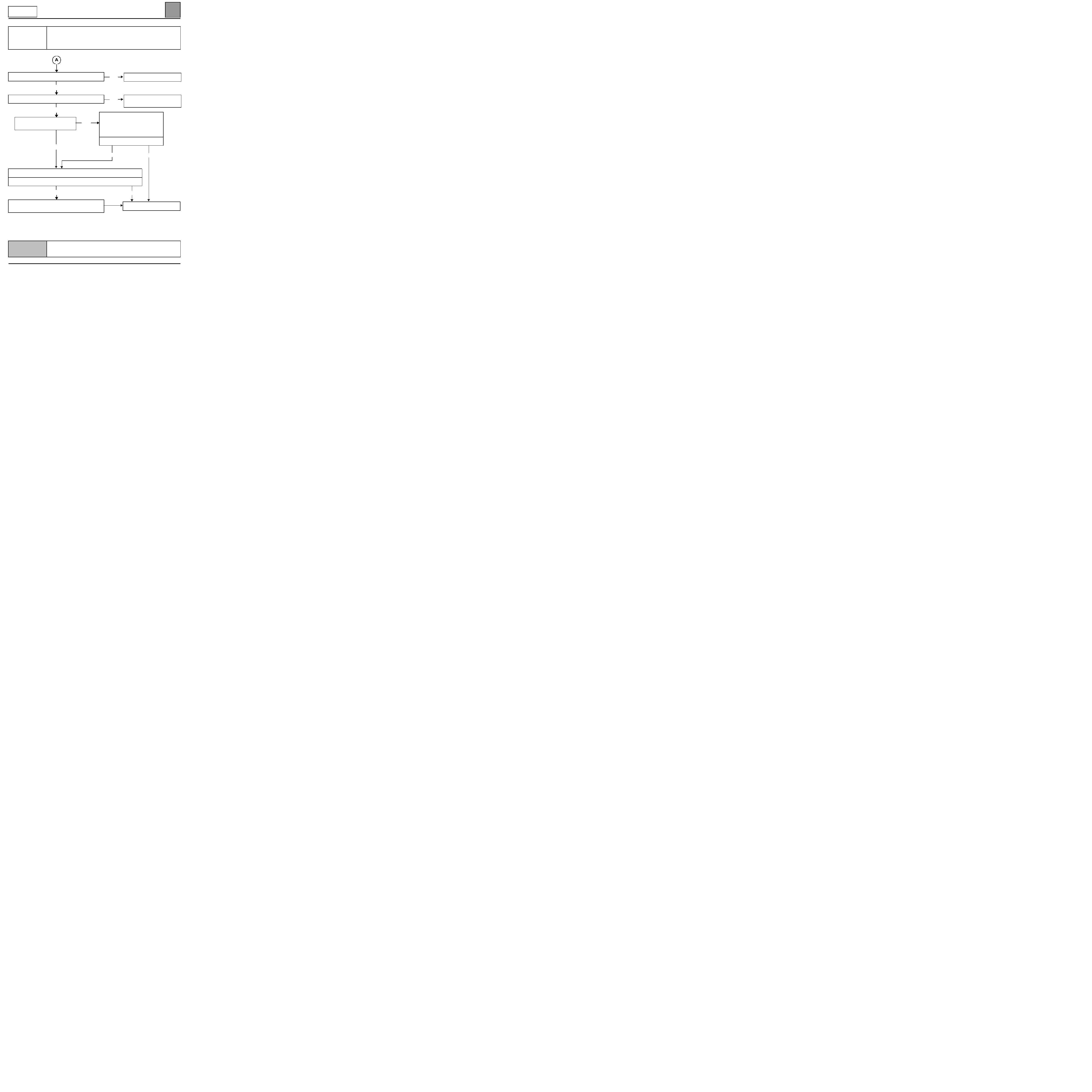
AUTOMATIC AIR CONDITIONING
Fault finding - Fault finding charts
62
62-61
CAREG
VDIAG No.: 06
CHART 6
CONTINUED
Is the air flow correct?
YES
Is the air distribution correct?
YES
Are the heater matrix pipes on the
bulkhead hot?
YES
Check that the heater matrix is not blocked, and clean or replace if necessary.
Is the fault still present?
YES
If the vehicle is fitted with thermoplungers, check that they
are operating correctly.
NO
Carry out a check on the coolant
circuit and ensure that the
thermostatic valve opens at the
correct temperature.
Replace the valve if necessary.
Is the fault still present?
YESNO
NO
End of fault finding.
NO
NO
See CHART 2, faulty air flow
See CHART 1, faulty air
distribution
AFTER REPAIR
Check that the system is operating correctly.
CAREG X65 - 1.0
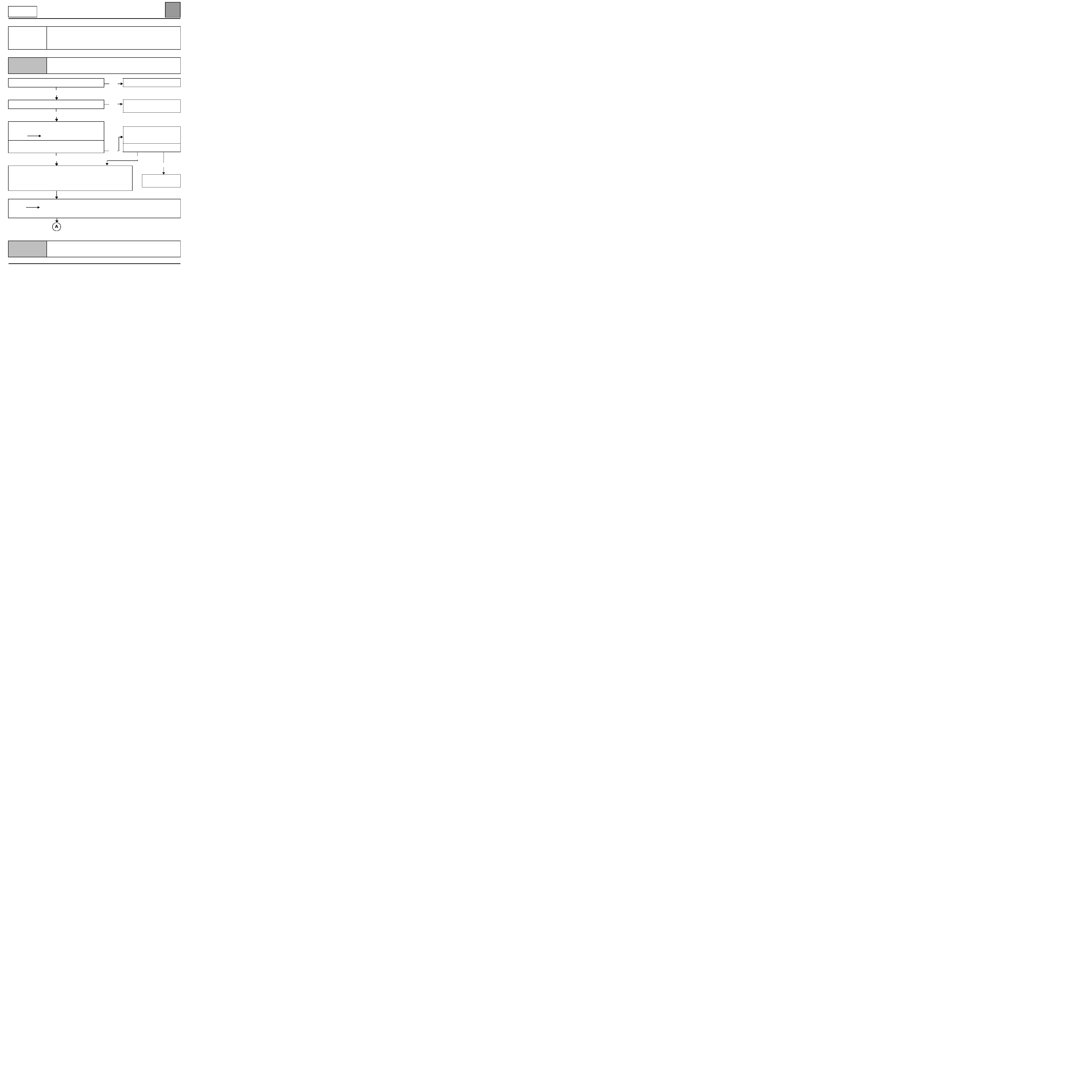
AUTOMATIC AIR CONDITIONING
Fault finding - Fault finding charts
62
CAREG
VDIAG No.: 06
CHART 7
TOO HOT
NOTES
Only refer to this customer complaint after a complete check using the diagnostic tool
Is the air flow correct?
YES
Is the air distribution correct?
YES
Using the diagnostic tool, check the air mixing control by
checking the mixing motor parameter.
PR012
mixing flap position.
Does the flap close fully?
(maximum cold position: 0 % displayed on tool)
YES
Run a conformity check of the sensors as the problem may arise from a
faulty signal from the temperature sensors (internal, external and delivery air).
Check that the interior air temperature sensor micro-turbine is in correct
working order (if it is faulty it may make the measurement incorrect).
Replace any faulty components.
Using the diagnostic tool, check that the air recirculation flap is in the external air position by checking status
ET021
air recirculation motor command.
Repair if necessary (see DF021).
NO
NO
NO
See CHART 2, faulty air flow.
See CHART 1, faulty air
distribution.
Carry out the fault finding test
for the mixing motor: DF010
mixing motor circuit.
Is the fault still present?
YES
NO
End of fault
finding.
AFTER REPAIR
Check that the system is operating correctly.
CAREG X65 - 1.0
62-62

AUTOMATIC AIR CONDITIONING
Fault finding - Fault finding charts
62
62-63
CAREG
VDIAG No.: 06
CHART 7
CONTINUED
Carry out a check on the coolant circuit and ensure that
the thermostatic valve opens at the correct temperature.
Replace the valve if necessary.
Is the fault still present?
YES
Run a conformity check on the engine coolant
temperature sensor (in the injection fault finding
procedure) and check that the engine cooling fan engages
at the right temperature.
Replace the coolant temperature sensor if necessary.
NO
End of fault finding.
AFTER REPAIR
Check that the system is operating correctly.
CAREG X65 - 1.0
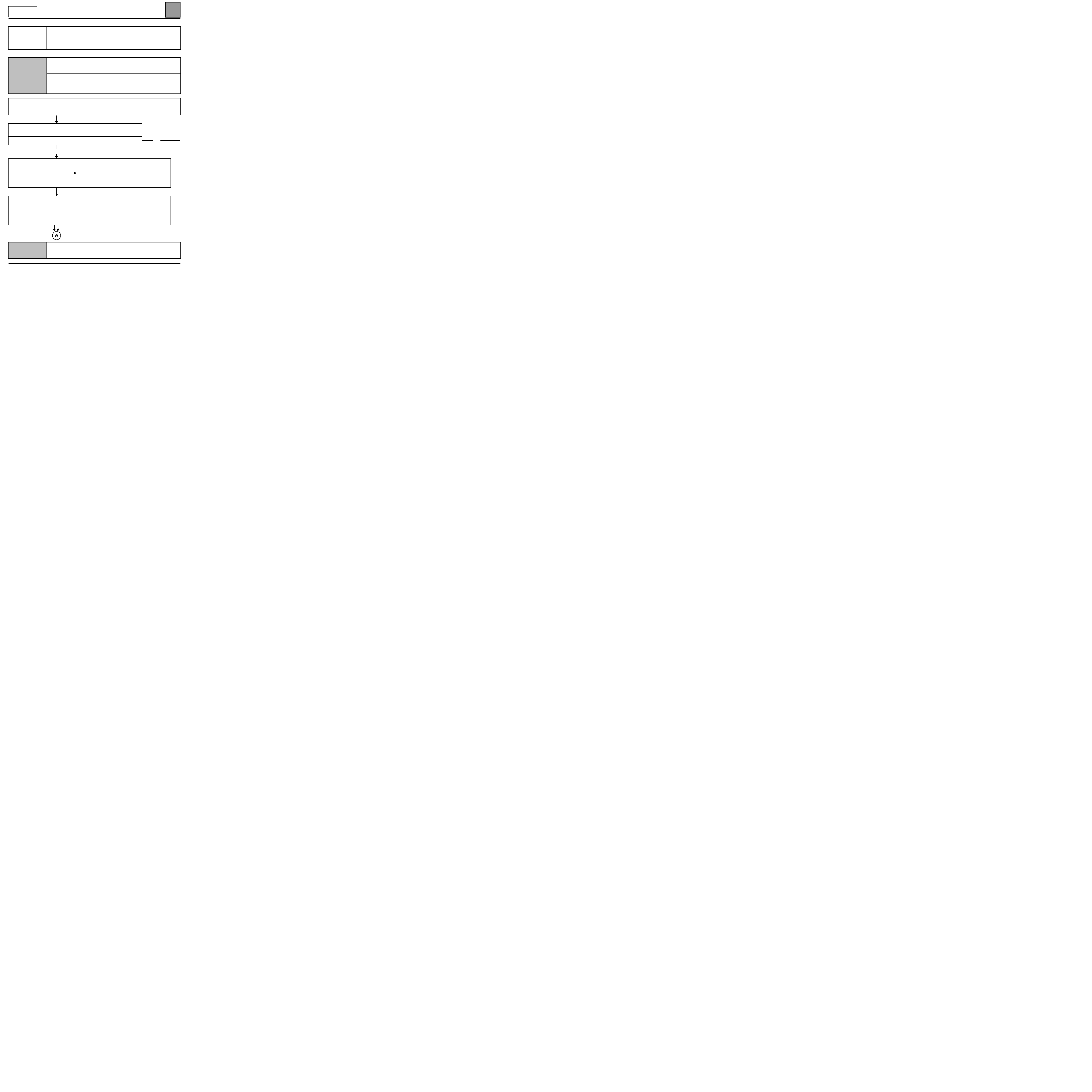
AUTOMATIC AIR CONDITIONING
Fault finding - Fault finding charts
62
62-64
CAREG
VDIAG No.: 06
CHART 8
NO COLD AIR
NOTES
Only refer to this customer complaint after a complete check using the diagnostic
tool
Special notes:
The compressor control, coolant pressure sensor and engine cooling fan are controlled
by the injection computer.
Check that the air circuit (particle filter, scuttle panel grille, air vents and extractors etc.) is not blocked.
Check that the evaporator is not blocked.
Repair, clean or replace the particle filter and the evaporator if necessary.
With the engine at idling speed, activate the clutch compressor command using
AC021
diagnostic tool
Does the compressor clutch jam?
NO
Connect the bornier in place of the computer and check the insulation, continuity and absence of
interference resistance
of the connection:
computer connector A track 24
injection computer
(refer to the injection diagrams
concerned).
Repair if necessary.
Carry out a fault finding test on the injection (faulty injection leading to a sub-standard performance
may prevent the heating and ventilation from functioning). Check that the engine cooling fan assembly
is working by activating the appropriate command (if the fan is faulty, climate control is not authorised).
If the injection reports a compressor control fault: carry out the relevant fault finding procedure (in the
injection Technical Note).
Repair if necessary.
YES
AFTER REPAIR
Check that the system is operating correctly.
CAREG X65 - 1.0

AUTOMATIC AIR CONDITIONING
Fault finding - Fault finding charts
62
62-65
CAREG
VDIAG No.: 06
CHART 8
CONTINUED
Check the condition of the climate control compressor
belt.
Replace it if necessary.
Is the tension correct?
YES
Using the diagnostic tool, check the air mixing control by
checking the parameter:
PR012
mixing flap position.
Does the flap close fully?
(maximum cold position: 0 % displayed on tool)
YES
Run a conformity check on the sensors as the problem may arise from a
faulty signal from the temperature sensors (internal, external and delivery air).
Check that the interior air temperature sensor micro-turbine is in correct
working order (if it is faulty it may make the measurement incorrect).
Replace any faulty components.
Check the cold loop by inspecting the condition of the pipes and ensuring that there are no refrigerant fluid
leaks
in the climate control system.
Carry out an injection fault finding procedure using the diagnostic tool, check that there is no faulty coolant
pressure sensor (pressurised or unpressurised) that might prevent the compressor from working.
Carry out a fluid charge test and recharge if necessary.
NO
NO
Retighten the compressor
belt
(refer to the engine section
concerned).
Carry out the fault finding test
for the mixing motor: DF010
mixing motor circuit.
Is the fault still present?
YES
NO
End of fault
finding.
AFTER REPAIR
Check that the system is operating correctly.
CAREG X65 - 1.0
AUTOMATIC AIR CONDITIONING
Fault finding - Fault finding charts
62
62-66
CAREG
VDIAG No.: 06
CHART 9
AIR TOO COLD
NOTES
Only refer to this customer complaint after a complete check using the diagnostic tool
Start the engine and switch on the climate control:
Does the compressor operate?
NO
Run a conformity check on the sensors as the problem may arise from a faulty signal
from the temperature sensors (internal, external and delivery air).
Check that the interior air temperature micro-turbine is in correct working order (if it is
faulty it may make the measurement incorrect).
Replace any faulty components.
Check that the delivery air temperature sensor is in place (it is located under the
glove compartment next to the mixing motor).
Using the diagnostic tool, check the air mixing control by
checking the parameter:
PR012
mixing flap position.
Does the flap open fully?
(maximum hot position: 100 % displayed on tool).
YES
Check the refrigerant fluid.
YES
NO
Carry out the fault finding
test for the mixing motor:
DF010
mixing motor.
Is the fault still
present?
YES
NO
End of fault
finding.
AFTER REPAIR
Check that the system is operating correctly.
CAREG X65 - 1.0

AUTOMATIC AIR CONDITIONING
Fault finding - Fault finding charts
62
62-67
CAREG
VDIAG No.: 06
CHART 10
UNPLEASANT ODOURS IN PASSENGER COMPARTMENT
NOTES
Only refer to this customer complaint after a complete check using the diagnostic tool
Ensure that the pollen filter is not blocked or worn.
Replace it if necessary.
Is the problem still present?
YES
Ensure that the evaporator outlet pipe is not blocked.
Repair if necessary.
Is the problem still present?
YES
Check that the heating unit is completely tight and
there are no leaks
into the engine compartment.
Repair if necessary.
Is the problem still present?
YES
Place the vehicle on a lift.
Run an extension through the evaporator outlet pipe to
apply the air conditioning freshener.
Spray in the complete contents of the can.
Leave the freshener to work for 15 minutes.
NO
NO
NO
End of fault finding.
End of fault finding.
End of fault finding.
AFTER REPAIR
Check that the system is operating correctly.
CAREG X65 - 1.0

AUTOMATIC AIR CONDITIONING
Fault finding - Fault finding charts
62
62-68
CAREG
VDIAG No.: 06
CHART 11
WATER IS PRESENT IN PASSENGER COMPARTMENT
NOTES
Only refer to this customer complaint after a complete check using the diagnostic tool
Pressurise the coolant circuit.
Is there any coolant leaking into the vehicle?
NO
Ensure that the evaporator outlet pipe is not blocked.
Repair if necessary.
Is the problem still present?
YES
The problem may be caused by ice in the evaporator.
Does the customer complain of water droplets coming out
of the air vents?
YES
See CHART 9.
YES
NO
NO
Repair.
End of fault finding.
The leak does not come from
the heating and ventilation
system.
AFTER REPAIR
Check that the system is operating correctly.
CAREG X65 - 1.0

AUTOMATIC AIR CONDITIONING
Fault finding - Fault finding charts
62
62-69
CAREG
VDIAG No.: 06
CHART 12
CONTROL PANEL LIGHTING FAILURE
NOTES
Only refer to this customer complaint after a complete check using the diagnostic tool
Check that the side light fuses are in good condition.
Check for the presence of a + 12 volt supply, when the side lights are on, on
track 1
of connector A of the climate control computer.
Is there a supply?
NO
Connect the bornier in place of the computer and check the insulation, continuity and absence
of interference resistance
of the connection:
computer connector A track 1
+ side lights (refer to the vehicle diagrams)
Repair if necessary.
Is the problem still present?
YES
Check the connection and condition of the computer output
connectors.
Connect the bornier in place of the computer and check the insulation,
continuity and absence of interference resistance
of the
connections:
computer connector A track 12
track 3
of the dimmer
earth
track 1
of the dimmer
Repair if necessary.
Is the problem still present?
YES
YES
NO
End of fault finding.
AFTER REPAIR
Check that the system is operating correctly.
CAREG X65 - 1.0

AUTOMATIC AIR CONDITIONING
Fault finding - Fault finding charts
62
62-70
CAREG
VDIAG No.: 06
CHART 12
CONTINUED
Check the resistance value of the dimmer by measuring
across:
track 1
and track 3 of the dimmer connector.
When the dimmer is operated, its resistance should vary
between 0 and 140
Ω
±
10
Ω
.
Replace the dimmer if this is not the case.
Is the problem still present?
YES
Replace
the computer (control panel).
NO
End of fault finding.
AFTER REPAIR
Check that the system is operating correctly.
CAREG X65 - 1.0
AUTOMATIC AIR CONDITIONING
Fault finding - Fault finding charts
62
62-71
CAREG
VDIAG No.: 06
CHART 13
Noisy compressor
NOTES
Only refer to this customer complaint after a complete check using the diagnostic tool
Check that the compressor belt is in good condition and check its tension (for engines without automatic
tensioner).
Replace the belt if necessary.
Check that the compressor is correctly positioned.
Repair if necessary.
Check the refrigerant fluid and look for leaks as the compressor may become noisy if it loses a significant
volume of fluid.
Refill if necessary.
If the fault persists, replace the climate control compressor.
AFTER REPAIR
Check that the system is operating correctly.
CAREG X65 - 1.0
Document Outline
Wyszukiwarka
Podobne podstrony:
SR 8 Adaptive Air Conditioning ULA[1]
6 4 1%20Ventilation%20in%20Air conditioned%20Premises
0502 Refrigerant circuit Model 126 with air conditioning system
HEATER & AIR CONDITIONER
Audel Hvac Fundamentals, Air Conditioning, Heat Pumps And Distribution Systems (Malestrom)
Manual Air Conditioning
Air Conditioning
Automatic Air Conditioning
Design Of Air Conditioning Ducts
Air conditioning sometimes does not work
Engine Management Fault Finding
Fault Finding And Troubleshooting
ABS Fault Finding
C102974 A SERVICE FAULT FINDING
19 air conditioning
SR 8 Adaptive Air Conditioning ULA[1]
6 4 1%20Ventilation%20in%20Air conditioned%20Premises
Chrysler voyager air conditioner fix ac
więcej podobnych podstron