
HP Color LaserJet 2500 printer
HP Parts Reference Guide™
www.hp.com/go/hpparts
Electronic Accessories
Cable (Interface)
C2950A
IEEE-1284 Bi-Tronics parallel cable - DB-25 (M) connector (type A) to 36 pin Centronics (M) connector (type B) -
2.0m (6.6ft) long
5063-1256
New Part for C2950A
C2951A
IEEE-1284 Bi-Tronics parallel cable - DB-25 (M) connector (type A) to 36 pin Centronics (M) connector (type B) -
3.0m (9.8ft) long
C6518A
Universal serial bus (USB) interface cable - Type 'A' connector to type 'B' connector - 2.0m (6.6ft) long
Interface (Product)
J3110A
Ethernet 10Base-T (RJ-45) EIO network internal print server PC board
J3111A
Ethernet 10Base-T/10Base2 and LocalTalk (RJ-45, BNC, LocalTalk) EIO network PCA
J4135A
JetDirect connectivity card - Has one USB port, one serial (DB9) port and one LocalTalk port - Plugs in the EIO slot
on selected DesignJet and LaserJet printers
J4167A
JetDirect 610N token ring LAN interface board - DB-9 and RJ-45 connectors
J6057A
JetDirect 615N internal print server (10Base-T and 100Base-TX) LAN interface board - Plugs into peripheral EIO
slot - Has a RJ-45 connector - Comes with software on CD-ROM and manual
J6057AR
JetDirect 615N internal print server (10Base-T and 100Base-TX) LAN interface board - Plugs into peripheral EIO
slot - Has a RJ-45 connector - Comes with software on CD-ROM and manual
J6058A
JetDirect 680N internal wireless IEEE-802.11b (Wi-Fi) print server - Plugs into peripheral EIO slot
Memory (Product)
C7845A
32MB, 100-pin SDRAM DIMM memory module
C7846A
64MB SDRAM - 100MHz synchronous DRAM - DIMM package
Q1887AX
New Part for C7846A
C9121A
128MB, 100MHz synchronous SDRAM DIMM memory module
Electronics/Power Cords
Cable
14
C9706-60104
Flat flexible cable - Connects between the DC controller board and the formatter board
15
RG5-6971-000CN
Cable assembly (two 3-pin connectors and a spad lug) - Power cable for the fusing assembly - Connects from the
fusing assembly connector to the chassis ground and the low voltage power supply board
16
RG5-6974-000CN
Cable assembly - Connects the toner cartridge E-label reader assembly on the carousel to the DC controller board
17
RG5-7106-000CN
Cable assembly (two 2-pin connectors) - Connects from the low voltage power supply board to the formatter board
18
RG5-7107-000CN
Cable assembly (8-pin, red wire) - (J402 to J134) Connects the low voltage power supply board to the DC controller
board
19
RG5-7108-000CN
Cable assembly (8-pin, Purple wire) - (J403 to J133) Connects the low voltage power supply board to the DC
controller board
20
RG5-7109-000CN
Cable assembly (two 7-pin connectors) - Connects the DC controller board to the fusing assembly connector
21
RG5-7114-000CN
Cable assembly (two connectors) with shield - Connects between the toner cartridge drive motor and the DC
controller board
22
RG5-7115-000CN
Cable assembly (two connectors) - Connects between the roller engaging sensor (PS714) and the DC controller
board
23
RG5-7117-000CN
Cable assembly (two connectors) - Connects the engaging sensor (PS 712) on the toner cartridge carousel to the
DC controller board
24
RG5-7122-000CN
Cable assembly - 'Y' type cable (three connectors) - The 14-pin connector splits into an 8-pin connector and a 6-pin
connector - Connects between the DC controller board and the optional paper tray connector
25
RG5-7123-000CN
Grounding cable assembly - Connects between the optional tray connector housing and the metal right side frame
assembly
26
RG5-7126-000CN
Cable assembly (two connectors) - Connects the Sub-high voltage board to the high voltage board
27
RG5-7128-000CN
Cable assembly (four connectors) - Connects between the DC controller board and the leading edge paper sensor
for the fusing assembly (PS720) and the waste toner sensor board
28
RG5-7129-000CN
Cable assembly (two connectors and two spade lugs) - Connects the toner cartridge contacts on the left carousel
side plate to the high voltage power supply
29
RG5-7130-000CN
High voltage cable assembly - Connects between the high voltage board spring contacts and the cables to the toner
cartridge carousel left plate assembly
30
RG5-7144-000CN
Upper cable assembly (with seven connectors) - Interconnects various upper level components to the DC controller
board
© 2004 Hewlett-Packard
1

HP Color LaserJet 2500 printer
HP Parts Reference Guide™
www.hp.com/go/hpparts
Electronics/Power Cords
Cable
31
RG5-7145-000CN
Front cable assembly (six connectors) - Interconnects various components on the front frame assembly and right
side to the DC controller board
32
RG5-7146-000CN
High voltage cable assembly (four connectors) - Connects between the high voltage power supply board and the DC
controller board
33
RH2-5524-000CN
Flat flexible cable (FFC) - Connects between the laser/scanner assembly and the DC controller board
Clutch
34
RH7-5366-000CN
Electromagnetic clutch assembly (24V) - Electrical clutch between the clutch drive gear and shaft - (CL1) Engages
the registration roller assembly, and (CL2) Engages the roller within the imaging drum/transfer assembly from the
main gear train
Connector
35
RH2-5519-000CN
Connector assembly - For optional paper tray - One mounts to the bottom right side of the printer middle frame
assembly (Interfaces 250 sheet tray), and the other to the bottom of the 250 sheet tray base assembly (Interfaces
500 sheet tray) - (2 used)
36
RH2-5520-000CN
Connector for the fusing assembly (F) - 7 small contol pins plus 3 separated high current pins - Mounts in the
connector housing mounted on the bottom pan of the printer
Cover
37
RB3-0120-000CN
Solenoid cover (Steel) - Cover for the multi-purpose tray pickup roller solenoid (SL92)
Drive Assembly
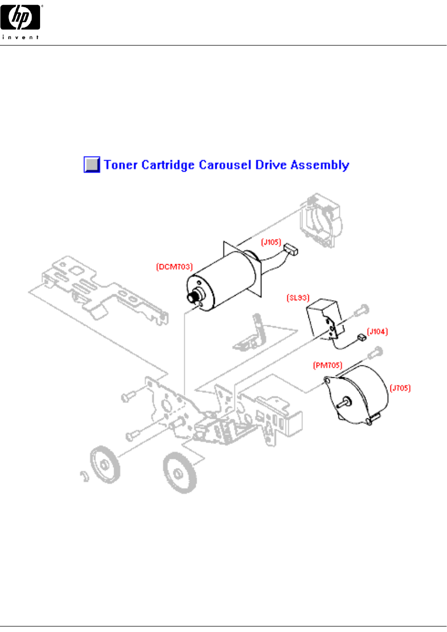
38
RG5-6911-000CN
Rotary drive assembly - Includes the carousel rotating motor (DCM703), toner cartridge drive motor (PM705),
developing rotary stopper solenoid (SL93), bracket, and gears - Mounts on the right top rear of the print engine
Fan
39
RH7-1537-000CN
Cooling fan (Panaflo Model FBA08T24H - 80mm X 80mm X 15mm high, DC brushless, 24V DC, 190mA) - (FM712)
Mounts in the airflow guide/fan bracket assembly on the left side of the printer
Ground Plane
40
RB2-9942-000CN
Grounding plate - Provides grounding for the top-of-page sensor and shielding for the density sensor boards -
Mounts on the top left of the front frame assembly
41
RB3-0119-000CN
Grounding plate - Grounds the paper pick-up solenoid cover to the right side metal chassis
Insulator
42
RB3-0056-000CN
Insulating sheet (Transparent plastic) - Mounts to the underside of the middle frame assembly
Laser/Scanner
43
RG5-6880-000CN
Laser/scanner assembly - Mounts in the center of the scanner support assembly
Lever
44
RB3-0179-000CN
Left side lock release lever - Part of locking system used to secure the fusing assembly in the printer
Motor
45
RF5-4010-000CN
Main motor assembly - Large motor mounted on a controller PC board - Mounts on the inside of the metal right side
frame assembly
RF5-4010-020CN
New Part for RF5-4010-000CN
46
RG5-6958-000CN
Rotary motor assembly - (DCM703) Rotates the four color toner cartridges in the carousel to position one of them for
printing
47
RH7-1533-000CN
Stepping motor - 24V DC - (PM704) Swings (or engages) the toner cartridge carousel in place to transfer toner -
Mounts in the recess on the left side of the rear frame assembly
48
RH7-1535-000CN
Stepping motor (24V) - (PM705) Used to drive the internal rollers and mechanisms in the toner cartridge when it
has been rotated in the printing position on the carousel
PC Board
49
C9145-69001
Formatter board assembly - Includes the formatter board and all the metal cage covers - Mounts towards the rear on
the metal right frame assembly
REQUIRES RETURN OF DEFECTIVE PART
C9145-67901
New Part for C9145-69001
50
C9705-69003
DC controller board - Mounts on the left side of the printer (Behind the formatter board assembly)
REQUIRES RETURN OF DEFECTIVE PART
RG5-6959-060CN
New Part for C9705-69003
51
RG5-6964-000CN
Carousel position and toner level photoelectric sensor PC board - 'L' Shaped PC board with the two sensors -
(PS51) Mounts on the left plate in the toner cartridge carousel
© 2004 Hewlett-Packard
2

HP Color LaserJet 2500 printer
HP Parts Reference Guide™
www.hp.com/go/hpparts
Electronics/Power Cords
PC Board
52
WG8-5382-000CN
Sensor PC board - Small board with flag activated photosensor - (PS718) Paper sensor for the multi-purpose tray,
(PS720) fusing assembly front of page sensor, and (PS716/PS717) paper feed/out sensors in the 250 sheet tray
assembly (four used)
53
RG5-6965-000CN
Waste toner sensor PC board - Small board with an LED and photoelectric sensor - Monitors the level of the excess
toner deposited in the imaging drum/transfer assembly - Mounts on the right side wall of the front frame assembly
54
RG5-6966-000CN
Top of page photoelectric sensor PC board - Includes the photoelectric top of page sensor and the print engine test
switch - (PS71 and SW71) Mounts in the upper left corner of the front frame assembly
55
RG5-6967-000CN
Registration sensor PC Board - Small board with flag activated photosensor - (PS711) Mounts in the registration
assembly on the underside of the middle frame
56
RH7-7146-000CN
Density photoelectric sensor PC board - (PS81) Mounts under the light blocking pad on the top of the front frame
assembly
Plate
57
RB3-0057-000CN
Transfer slide plate - Small 'U' shaped metal insert plates - Mount in the bushing wells for the transfer roller on the
middle frame assembly (two used)
58
RB3-0065-000CN
Contact plate - copper clad metal spring - Holds the left end of the small 500 Meg-ohm resistor - Mounts on the left
side of the middle frame below the entrance guide assembly
RB3-0066-000CN
Contact plate - copper clad metal spring - Holds the right end of the small 500 Meg-ohm resistor - Mounts on the left
side of the middle frame below the entrance guide assembly
60
RB3-0286-000CN
Contact plate - Runs between the shaft on the registration roller and the metal entrance guide assembly
Power Cord
8120-6800
Power cord (Flint Gray) - 16 AWG, 2.3m (7.5ft) long - Has straight (F) receptacle (For 240V in Israel)
8120-6809
Power cord (Dove Gray) - 2.3m (7.5ft) long - Has straight (F) receptacle (For 240V operation in the United Kingdom,
Hong Kong, Singapore, Malaysia)
8120-6810
Power cord (Flint Gray) - 2.3m (7.5ft) long - Has straight (F) receptacle (For 240V operation in Australia, New
Zealand)
8120-6811
Power cord (Flint Gray) - 17 AWG, 2.3m (7.5ft) long - Has straight (F) receptacle (For 220V in Europe, Saudi Arabia,
South Africa, India, and Korea)
8120-6812
Power cord (Flint Gray) - 18 AWG, 2.3m (7.5ft) long - Has straight (F) receptacle (For 120V in the USA, Canada,
Mexico, Philippines, and Taiwan)
8120-6813
Power cord (Flint Gray) - 17 AWG, 2.3m (7.5ft) long - Has straight (F) receptacle (For 220V in South Africa, Saudi
Arabia, and India)
8120-6814
Power cord (Flint Gray) - 17 AWG, 2.3m (7.5ft) long - Has straight (F) receptacle (For 220V in Denmark)
8120-6815
Power cord (Flint Gray) - 17 AWG, 2.3m (7.5ft) long - Has straight (F) receptacle (For 220V in Switzerland)
Power Supply
69
RG5-6960-000CN
High voltage power supply board (HVT) assembly - Has contacts for the eight high voltage springs in the printer -
Mounts in the bottom pan (Towards the front of the printer)
70
RG5-7124-000CN
Sub-high voltage board - Small auxillary PC board - Mounts in a holder just above the high voltage board
71
RH3-2241-000CN
Low voltage power supply - For 110V to 127V AC operation - Includes the AC power input connector and power
switch - Mounts in the bottom pan towards the rear of the printer
72
RH3-2243-000CN
Low voltage power supply - For 220V to 240V AC operation - Includes the AC power input connector and power
switch - Mounts in the bottom pan towards the rear of the printer
Reader
73
RG5-6956-000CN
E-label reader (contact board ONLY) - Connects the cartridge nonvoliatile memory to the DC controller board -
Mounts in the E-label reader assembly
74
RG5-6957-000CN
E-label reader assembly - Connects cartridge nonvoliatile memory to the DC controller board - One for the imaging
drum/tranfer assembly, the other for toner cartridges - One mounts to the the front frame assembly, the other to the
toner cartrige carousel assembly
Sideplate
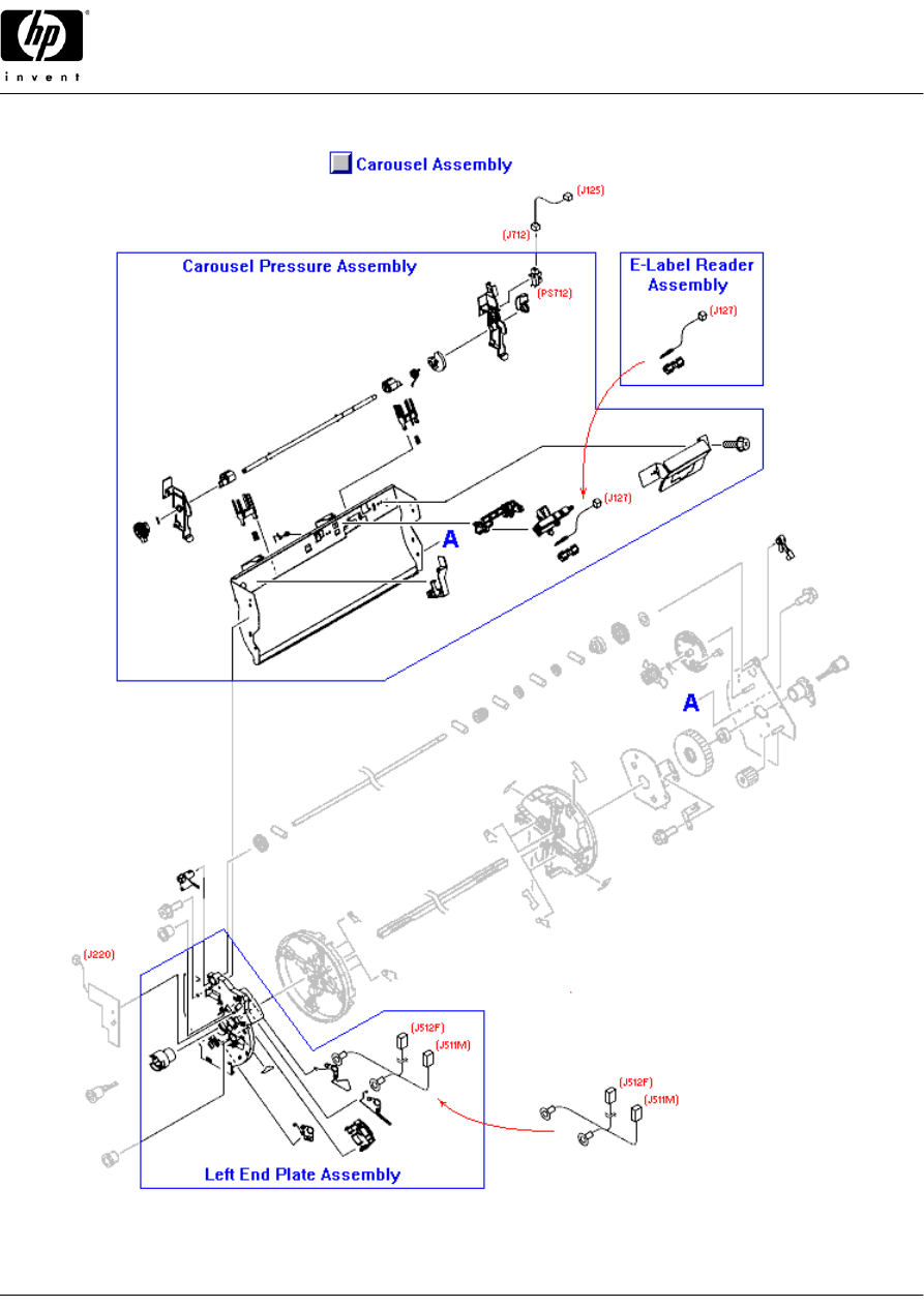
75
RG5-6942-000CN
Left side carousel plate assembly - End plate under the rotational toner cartridge carousel - Includes all of the high
voltage contacts for the toner cartridges - Mounts on the metal carousel support frame
Solenoid
76
RH7-5337-000CN
Solenoid assembly - (SL92) Lever on the solenoid disengages the stop on the drive gear on the paper pick-up roller
for the multi-purpose input tray (tray 1)
77
RH7-5340-000CN
Solenoid assembly - (SL93) Engages to stop rotation when the proper toner cartridge on the carousel is in place for
printing
© 2004 Hewlett-Packard
3

HP Color LaserJet 2500 printer
HP Parts Reference Guide™
www.hp.com/go/hpparts
Electronics/Power Cords
Spring
78
RB3-0016-000CN
Electrical contact spring - Spring steel wire with compression springs formed on both ends - One end provides
upward pressure on the right bushing for the transfer roller - Connects to high voltage board
79
RB3-0042-000CN
Electrical contact spring - Mounts on the middle frame assembly behind the transfer roller - Of the four similar
springs, this one is next to the one on the far left - Connects to high voltage board
80
RB3-0043-000CN
Electrical contact spring - Mounts on the middle frame assembly behind the transfer roller - Of the four similar
springs, this one is on the far right - Connects to high voltage board
81
RB3-0044-000CN
Electrical contact spring - (Front) Provides high voltage to the toner cartridge via a cable assembly and connection
through the carousel plate assembly - Connects to the high voltage board
82
RB3-0045-000CN
Electrical contact spring - (Rear) Provides high voltage to the toner cartridge via a cable assembly and connection
through the carousel plate assembly - Connects to the high voltage board
83
RB3-0046-000CN
Electrical contact spring - Mounts on the middle frame assembly behind the transfer roller - Of the four similar
springs, this one is just to the left of the one on the far right - Connects to high voltage board
84
RB3-0047-000CN
Electrical contact spring - Mounts on the underside of the middle frame assembly - Connects to high voltage board
85
RB3-0048-000CN
Electrical contact spring - Mounts on the middle frame assembly behind the transfer roller - Of the four similar
springs, this one is on the far left - Connects to the high voltage board
Switch
86
RH7-6051-000CN
Microswitch with lever activator - (SW2) Senses when the top cover is open - Mounts in a holder on the scanner
support assembly
Thermistor
87
RH7-7149-000CN
Thermistor - (TH3) For detecting internal temperature - Mounts to the right side frame assembly just above the DC
controller board
External Case Parts
Arm
88
RB3-0089-000CN
Top cover rack arm (Black) - Plastic arm with teeth on bottom edge - Disengages the imaging drum/transfer
assembly drive cams when the top door is open - Mounts on the right side of the top cover door
Bezel
89
RB3-0035-000CN
Interface bezel (Quartz Gray plastic) - Vertical cover that surronds the interface connectors - Mounts on the right
rear of the printer
Control Panel
90
RG5-6927-000CN
Control panel assembly (mechanical only) - Includes the 'Rotate Carousel', 'Cancel Job' and the 'Go' buttons, plus
the various indicator light pipes - All switches and LED's are on the formatter PC board - Mounts to the top of the
right cover assembly
Cover
91
RB3-0030-000CN
Upper rear cover (Quartz Gray plastic) - Mounts on the upper rear of the printer above the face-up output tray door
92
RB3-0032-000CN
Face-down paper output cover (L-Shaped blue plastic) - Serves as the rear of the tray for the face-down output tray
on top of the printer - Mounts in the upper rear of the printer mechanism
93
RB3-0102-000CN
Front inner cover (blue plastic) - Mounts on the front frame above the multi-purpose input tray
94
RB3-0103-000CN
Front lower cover (blue plastic) - Front lower strip below the multi-purpose input tray - Has recessed area for the
printer logo
95
RG5-6900-000CN
Top cover assembly (blue plastic) - Includes the molded-in face-down output tray and the lift-up top cover door
assembly
96
RG5-6953-000CN
Right side cover assembly (Quartz Gray plastic) - Includes the DIMM memory door - Mounts on the right side of the
printer
97
RG5-6902-000CN
Left side cover assembly (Quartz Gray plastic) - Includes the power switch button, rod and spring (The power switch
is located on the low voltage power supply board) - Mounts on the left side of the printer
98
RB3-0028-000CN
Left side cover ONLY (Quartz Gray plastic) - Does not include any attaching parts - Mounts on left side of printer
Door
99
RB3-0033-000CN
DIMM memory door (Quartz Gray perforated plastic) - Access door for adding or removing printer memory - Mounts
on the right side cover
100
RF5-4007-000CN
Top cover door (blue plastic) - For accessing the toner cartridges and the imaging drum/transfer assembly - Mounts
to the top cover frame
© 2004 Hewlett-Packard
4

HP Color LaserJet 2500 printer
HP Parts Reference Guide™
www.hp.com/go/hpparts
External Case Parts
Foot
101
RB2-6297-000CN
Rubber foot - Square self-adhesive rubber foot - Mounts on the rear of the middle frame assembly - Printer foot (two
used)
Holder
102
RB3-0006-000CN
Holder - Housing for the fusing connector assembly - Mounts on the bottom pan of the printer
Label
103
RS6-8662-000CN
Image cartridge label - Shows the imaging drum/transfer assembly removal steps - Mounts on the right side of the
front inner cover (Visible when the top cover is lifted)
Lever
104
RB3-0178-000CN
Right side lock release lever - Part of locking system used to secure the fusing assembly in the printer
Rod
105
RB3-0037-000CN
Power switch rod - Goes between the power button and the power switch on the low voltage power supply board -
Mounts on the left side cover
Shaft
106
RB2-4933-000CN
Lock release shaft (Small shaft with locking tab) - Does NOT include the lock release lever - Used to secure the
fusing assembly in the printer (2 used)
Spring
107
RS6-2759-000CN
Power switch spring - Provides tension for power switch button - Mounts on the left side cover
Tray
108
RB3-0176-000CN
Face-Up output tray door (ONLY) - Pull-down tray door for face-up output - Mounts to the top of the locking bracket
on the fusing assembly
109
RG5-6931-000CN
Face-up output tray assembly - Includes the pull-down door and fusing assembly locking bracket (Does NOT include
the lock releases) - Pull-down tray door for face-up output - Mounts to the rear of the fusing assembly
Fusing Assembly Parts
Bushing
110
RB2-2973-000CN
Support bushing - Mounts on each end of the pressure roller in the fusing assembly
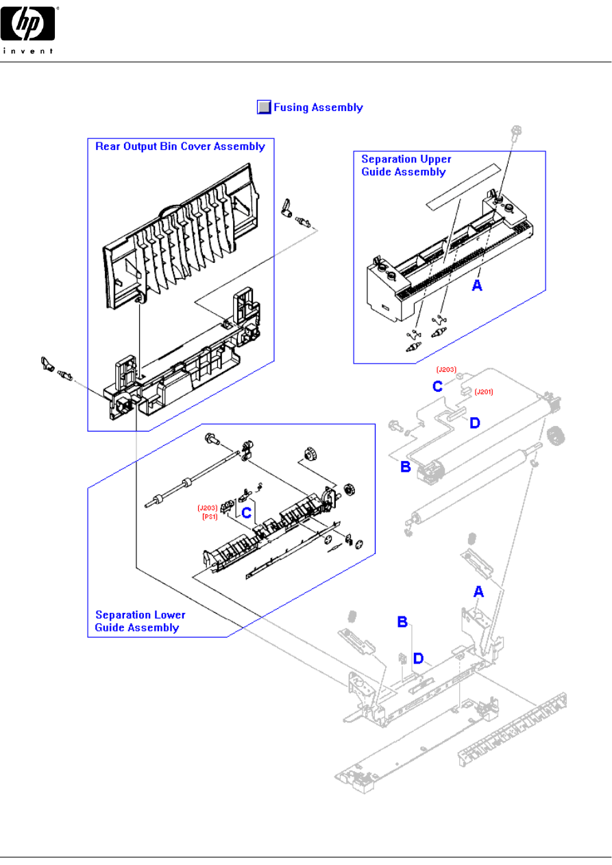
Fusing Assembly
111
RG5-6903-000CN
Fusing assembly - For 110V to 127V AC operation - Bonds the toner to the paper with heat - Slides in and locks in
lower rear of printer
112
RG5-6913-000CN
Fusing assembly - For 220V to 240V AC operation - Bonds the toner to the paper with heat - Slides in and locks in
lower rear of printer
Guide
113
RG5-6929-000CN
Separation guide assembly - Includes the plastic guide, label, and the two small spring loaded rollers - Upper case
and paper guide for the fusing assembly
114
RG5-6930-000CN
Lower separation guide assembly - Includes the guide bracket, paper output sensor (PS1) and flag, exit drive shaft
with two rubber rollers, shaft gear, and idler gear - Mounts in the lower rear on the fusing assembly
Shaft
115
RB2-4933-000CN
Lock release shaft (Small shaft with locking tab) - Does NOT include the lock release lever - Used to secure the
fusing assembly in the printer (2 used)
Other Accessories
Cartridge
116
C9700A
HP Color LaserJet smart Black print cartridge - Will print approximately 5,000 pages at 5% coverage
117
C9701A
HP Color LaserJet smart Cyan print cartridge - Will print approximately 5,000 pages at 5% coverage
118
C9702A
HP Color LaserJet smart Yellow print cartridge - Will print approximately 5,000 pages at 5% coverage
119
C9703A
HP Color LaserJet smart Magenta print cartridge - Will print approximately 5,000 pages at 5% coverage
120
C9700-67901
HP Color LaserJet smart Black print cartridge - Will print approximately 5,000 pages at 5% coverage - For CREW
fulfillment
121
C9701-67901
HP Color LaserJet smart Cyan print cartridge - Will print approximately 5,000 pages at 5% coverage - For CREW
fulfillment
122
C9702-67901
HP Color LaserJet smart Yellow print cartridge - Will print approximately 5,000 pages at 5% coverage - For CREW
fulfillment
123
C9703-67901
HP Color LaserJet smart Magenta print cartridge - Will print approximately 5,000 pages at 5% coverage - For CREW
fulfillment
© 2004 Hewlett-Packard
5

HP Color LaserJet 2500 printer
HP Parts Reference Guide™
www.hp.com/go/hpparts
Other Accessories
Cleaning Supplies
5090-3379
Toner cleaning cloth - Specially treated cloth for absorbing toner (1 per package) - Ideal for clening up toner spills
Drum
125
C9704A
Imaging drum/transfer assembly cartridge - Inserts into printer through the top door - Life expectancy is 20,000
pages for black print only, 5,000 pages for color (Typical combined life is approximately 6,000 to 8,000 pages)
126
C9704-67901
Imaging drum/transfer assembly cartridge - Inserts into printer through the top door - Life expectancy is 20,000
pages for black print ONLY, 5,000 pages for color (Typical combined life is approximately 6,000 to 8,000 pages) -
For CREW fulfillment
Manual
5851-1468
LaserJet printer family paper specification guide
C9706-90926
HP Color LaserJet 2500 series service manual
Paper
Q1298A
LaserJet Satin finish tough paper - A size (8.5 x 11-inches) - Will not tear and will withstand outdoor weather
conditions - Can print on both sides
Q1298B
LaserJet Satin finish tough paper - A4 size (21.0cm x 29.7cm) - Will not tear and will withstand outdoor weather
conditions - Can print on both sides - 50 sheets per box
Tray Assembly
C9699A
Optional 500 sheet paper input tray - Includes tray base which attaches to tray 2, and the slide out paper tray -
Accommodates 216mm x 279mm (8.5 x 11 inches) or 210mm x 279mm (8.3 x 11.7 inches) media - Optional 250
sheet tray must be installed first
Other Internal Parts
Airflow Guide
132
RB2-9904-000CN
Airflow Guide (duct) - Black plastic insert piece which runs the width of the printer and has an air flow hole on right
side - Directs air flow from the fan on the left side of the printer to the fusing assembly - Snap locks in center rear of
printer
133
RB3-0025-000CN
Airflow guide (duct) / fan holder bracket assembly (Quartz Gray plastic) - Mounts on the left metal side frame
assembly
Bushing
134
RB2-9808-000CN
Bushing/shaft retainer assembly (Black plastic) - Holds the rotation drive shaft in the right side plate of the toner
cartridge carousel (rotary) assembly
135
RB2-9809-000CN
Bushing/shaft retainer assembly (White plastic) - Holds the rotation drive shaft in the left side plate of the toner
cartridge carousel (rotary) assembly
136
RS5-1635-000CN
Shaft bushing - Mounts on the plate of the multi-purpose paper pick-up gear assembly
137
RS5-1637-000CN
Bushing (black plastic) - mounts on the left end of the registration roller assembly
138
RS5-1638-000CN
Bushing - For the registration roller gear drive shaft on the right side of the front frame assembly, and the left side of
the feed roller in the 250 sheet paper input tray assembly
Carousel
139
RG5-6910-080CN
Carousel (Rotary) assembly - Includes the carousel assembly, the support assembly, end plates, drive gears and
shaft, sensors, and cables - Mounts towards the rear of the printer in front of the rear frame assembly
Clip
140
WT2-5056-000CN
Cable clip - Mounts in the opening on the cover for the paper pick-up solenoid
141
WT2-5737-000CN
Cable clip - Mounts on the base assembly pan (two used)
142
XD2-1100-502CN
E-ring clip - Secures the dual gear to the drive shaft which drives the registration roller - Located on the inside of the
front frame assembly
Cover
143
RB3-0052-000CN
Gear Cover (Small Black plastic cover) - Protects the idler gear for the transfer roller - Mounts toward the left side of
the middle frame assembly
144
RB3-0104-000CN
Roller cover - Covers the multi-purpose paper pick-up roller assembly - Mounts in the lower portion of the front
frame assembly
145
RB3-0120-000CN
Solenoid cover (Steel) - Cover for the multi-purpose tray pickup roller solenoid (SL92)
Damper
146
RB2-6248-000CN
Damper assembly (Gray plastic piece with small 13 tooth gear on it) - Helps to reduce clunking when the paper pick-
up roller is engaged - engages the paper pick-up roller
© 2004 Hewlett-Packard
6

HP Color LaserJet 2500 printer
HP Parts Reference Guide™
www.hp.com/go/hpparts
Other Internal Parts
Flag
147
RB2-9925-000CN
Sensor arm and flag - Activates the photosensor (Does NOT include the roller) - For the Leading edge paper sensor
for the fusing assembly (PS720) - Protrudes up through the feed plate on the middle frame assembly
148
RB3-0135-000CN
Test print flag (Black lever) - Used to activate the print engine test switch - Mounts in a metal holder in the upper left
of the front frame assembly
Gear
149
RB3-0022-000CN
22 tooth gear (Black plastic) - Small gear with diagonally cut teeth - Idler gear between the transfer roller assembly
and the feed drive shaft - Mounts on the left side of the middle frame assembly
150
RB3-0091-000CN
16 tooth gear (Black plastic) - Gear with large stop tooth and shaft lock tab - Used as part of the mechanism to
disengage the drive cams for the imaging drum/transfer assembly - Mounts on the inside of the right side metal
chassis assembly
151
RB3-0092-000CN
15 tooth gear with drive shaft (Black plastic) - Used as part of the mechanism to disengage the drive cams for the
imaging drum/transfer assembly - Mounts on the right side metal chassis frame
152
RS7-0418-000CN
26 tooth gear (Black plastic) - Has 1/8th portion of gear cut away - Mounts on the end of the paper pick-up roller for
the multi-purpose input tray (tray 1)
153
RS7-0424-000CN
Dual gear - 20 tooth / 40 tooth - Mounts on the right side of the front frame assembly
154
RS7-0425-000CN
30 tooth gear (White plastic) - Part of the drive gears for the registration roller - Mounts on inside of the front frame
assembly on the right side
155
RS7-0426-000CN
Dual gear - 26 tooth / 50 tooth (White plastic) - Part of the drive gears for the registration roller - Mounts on inside of
the front frame assembly on the right side
156
RS7-0428-000CN
30 tooth gear (White plastic) - Mounts on the end of the registration roller drive shaft
157
RS7-0429-000CN
26 tooth gear (White plastic) - Has recess for shaft drive pin - Mounts on the right side of the front fame assembly
158
RS7-0435-000CN
Dual gear - 32 tooth / 37 tooth (White plastic) - Drives the upper top bin output roller - Mounts on the right side of the
rear frame assembly
159
RS7-0436-000CN
Dual gear - 37 tooth / 43 tooth (White plastic) - Part of the gear train for driving the upper top bin output roller -
Mounts on the right side of the rear frame assembly
160
RS7-0437-000CN
51 tooth gear (White plastic) - Main drive gear for both the upper and lower top bin output rollers
Gear Assembly
161
RG5-6938-000CN
Gear assembly - Metal plate with two White plastic gears attached - Part of the drive gears for the paper pick-up
roller for the multi-purpose input tray (tray 1) - Mounts on the right side of the front frame assembly
Ground Plane
162
RB2-9942-000CN
Grounding plate - Provides grounding for the top-of-page sensor and shielding for the density sensor boards -
Mounts on the top left of the front frame assembly
163
RB3-0119-000CN
Grounding plate - Grounds the paper pick-up solenoid cover to the right side metal chassis
Guide
164
RB2-9903-000CN
Cable guide (Quartz Gray plastic) - Protects and supports the upper cable assembly - Mounts to the right rear on the
laser/scanner support assembly
165
RB2-9912-000CN
Top output bin guide - Small curvered ribbed black plastic piece - Snaps on the rear of the printer just below the
upper top bin output roller (two used)
166
RB2-9954-000CN
Left paper feed guide (small Black plastic arm) - Mounts to the left of the separation pad assembly on the lower front
frame assembly
167
RB2-9955-000CN
Right paper feed guide (small Black plastic arm) - Mounts to the right of the separation pad assembly on the lower
front frame assembly
168
RG5-6935-000CN
Left cartridge guide assembly - For the imaging drum/transfer assembly - Mounts on the left metal side frame
Holder
169
RB2-9924-000CN
Sensor assembly mounting holder - For mounting the leading edge paper sensor for the fusing assembly (PS720) -
Mounts to the underside of the middle frame assembly
170
RB3-0023-000CN
Interlock switch holder (Quartz Gray plastic) - Mounts to the laser/scanner support assembly - Towards the left rear
of the printer
Insulator
171
RB3-0007-000CN
Insulating sheet (Transparent plastic) - Mounts between the bottom pan and the high and low voltage power supply
boards
172
RB3-0056-000CN
Insulating sheet (Transparent plastic) - Mounts to the underside of the middle frame assembly
© 2004 Hewlett-Packard
7

HP Color LaserJet 2500 printer
HP Parts Reference Guide™
www.hp.com/go/hpparts
Other Internal Parts
Pad
173
RF5-4047-000CN
Light blocking pad assembly - Black plastic frame with soft rubber gasket and stiff conductive Mylar piece
(grounded) - Mounts to the top center of the front frame assembly
Plate
174
RB2-9916-000CN
Mounting/grounding plate - For the engaging motor (PM704) - Mounts in the recess on the upper left side of the rear
frame assembly
Pressure Assembly
175
RG5-6943-000CN
Carousel pressure (support) assembly - Includes the main rear support, E-label reader assembly, engaging sensor,
and the engaging rod shaft - Primary support structure for the toner cartridge carousel
Rack Slide
176
RB3-0090-000CN
Rack slide - White plastic piece with gear teeth layed out in rack form on both sides - Part of the mechanism that
disengages the imaging drum/transfer assembly cams when the top cover is opened - Mounts vertically on the metal
right side frame
Shaft
177
RB3-0060-000CN
Idler gear shaft - Short metal rod - Shaft for the transfer and feed drive idler roller - Mounts on the left side of the
middle frame assembly
Shield
178
RB2-9932-000CN
RFI shield - Parallel wire form mounted over the fan - Mounts on the fan air duct assembly on the left side of the
printer
Sideplate
179
RG5-6932-060CN
Right side plate assembly - Includes the front half of the metal frame assembly, gears, imaging drum/transfer
assembly drive cams, cover engaging mechanism, roller engaging clutch (CL2), and main drive motor (DCM701) -
Mounts on the right side
RG5-6932-070CN
New Part for RG5-6932-060CN
180
RG5-6934-000CN
Right rear side plate assembly - Includes the rear half of the metal right side plate, the fusing assembly drive motor
and the three associated gears - Mounts on rear half of right side of printer
Spring
181
RB3-0121-000CN
Right retaining spring - Helps to secure and ground the imaging drum/transfer assembly in the printer - Mounts on
the upper right side of the front frame assembly
182
RB3-0122-000CN
Left retaining spring - Helps to secure the imaging drum/transfer assembly in the printer - Mounts on the upper left
side of the front frame assembly
183
RS6-2766-000CN
Tension spring - Provides a small amount of return tension for the sensor flag arm on the leading edge sensor for
the fusing assembly (PS720)
Support
RB3-0062-000CN
PC board support (Black plastic holder) - For mounting the small sub-high voltage board above the high voltage
board
185
RG5-6907-000CN
Laser/scanner support assembly (sheet metal plate) - Crossmember between the two side frames - Support for the
laser/scanner assembly, the toner cartridge carousel drive motor, and the cover interlock switch assembly
Tray
186
RB3-0019-000CN
Toner catch tray (curved Black plastic piece) - Holds residual toner from photosensitive drum - Mounts just below
the toner cartridge carousel on the bottom frame assembly
Paper Input Tray Parts
Guide
187
RG5-6951-000CN
Paper guide assembly - Paper width adjustable guide assembly for the multi-purpose front input tray (tray 1) -
Mounts with the two hinges on the lower portion of the front frame assembly
Hinge
188
RB2-3041-000CN
Tray hinge - For the left side of the multi-purpose front input tray (tray 1) - Mounts in the lower portion of the front
frame assembly
189
RB2-3042-000CN
Tray hinge - For the right side of the multi-purpose front input tray (tray 1) - Mounts in the lower portion of the front
frame assembly
Spring
190
RS6-2030-000CN
Tension spring - Provides support tension for the multi-purpose front input tray guide assembly (two used)
© 2004 Hewlett-Packard
8

HP Color LaserJet 2500 printer
HP Parts Reference Guide™
www.hp.com/go/hpparts
Paper Input Tray Parts
Tray Assembly
191
RG5-6937-000CN
Multi-purpose front input tray assembly (tray 1) - Includes the front cover piece, pull-out paper support, and the flip-
out extender - Mounts on front of printer (on the front frame assembly)
Paper Path Parts
Belt
192
RB1-8668-030CN
Feed guide drive belt - Small belt approximately 5/16 inch wide with 'A' shaped ribs on it - Between the feed drive
roller and the small center roller - Driven via the transfer roller gear train
193
RB3-0063-000CN
Feed belt - Small black rubber belt approximately 1/8 inch wide with little 'A' shaped ribs on it - Goes between the
feed drive roller and the pulley rollers (eight used)
Bushing
194
RB2-3043-000CN
Left roller bushing - Acts as the bearing and retainer for the left end of the paper pick-up roller assembly (tray 1) -
Mounts on the left side of the front frame assembly
195
RB2-3044-000CN
Right roller bushing - Acts as the bearing and retainer for the right end of the paper pick-up roller assembly (tray 1) -
Mounts on the right side of the front frame assembly
196
RB3-0014-000CN
Bushing assembly (black plastic bushing with small guide roller on top) - Holds the right end of the transfer roller
assembly in the middle frame assmebly
Drum
197
C9704A
Imaging drum/transfer assembly cartridge - Inserts into printer through the top door - Life expectancy is 20,000
pages for black print only, 5,000 pages for color (Typical combined life is approximately 6,000 to 8,000 pages)
198
C9704-67901
Imaging drum/transfer assembly cartridge - Inserts into printer through the top door - Life expectancy is 20,000
pages for black print ONLY, 5,000 pages for color (Typical combined life is approximately 6,000 to 8,000 pages) -
For CREW fulfillment
Flag
199
RB2-9925-000CN
Sensor arm and flag - Activates the photosensor (Does NOT include the roller) - For the Leading edge paper sensor
for the fusing assembly (PS720) - Protrudes up through the feed plate on the middle frame assembly
200
RB3-0111-000CN
Paper flag - Plastic rod with paper sensing flag on one end and sensor activator flag on the other - Senses paper
coming from the multi-purpose front input tray (tray 1)
Guide
201
RF5-4049-000CN
Entrance guide assembly - Angled metal guide between the registration roller and the transfer roller - Mounts to the
middle frame assembly
Pad
202
RF5-4012-000CN
Separation pad assembly - Includes the separation pad, holder and spring - Mounts below the multi-purpose front
input (tray 1) pick-up roller assembly
Plate
203
RB3-0010-000CN
Feed plate - Center metal plate with slots that the ribs on the middle frame assembly go through - Mounts behind the
transfer roller on the middle frame assembly
Pulley
204
RB3-0061-000CN
Pulley roller (accommodates three feed belts) - Small black roller approximately 3.49cm (1.75-inches) long with
three ball type pulleys - Mounts just behind the tranfer roller in the middle frame assembly (two used)
205
RB3-0067-000CN
Pulley roller (accommodates one feed belt) - Small black roller approximately 1.59cm (0.625-inch) long with one ball
type pulley - Mounts just behind the tranfer roller in the middle frame assembly (two used)
Roller
206
RB2-7195-000CN
Sensor flag roller (small White plastic roller) - Mounts in the sensor arm flag for the leading edge paper sensor for
the fusing assembly (PS720)
207
RB2-9908-000CN
Pressure roller (small black hard plastic 'disked' roller) - Rides up against the upper top bin output roller on the top
rear of the printer (two used)
208
RB2-9909-000CN
Pressure roller (small Black hard plastic 'solid' roller) - Rides up against the lower top bin output roller on the middle
rear of the printer (two used)
209
RB3-0012-000CN
Belt roller - Small oval shaped roller approximately 1-3/4 inches long - Mounts toward the center of the metal feed
plate on the middle frame assembly
210
RB3-0160-000CN
Paper pick up roller (D-shaped) - Mounts on the paper pick up roller assembly for the multi-purpose front input tray
(tray 1)
© 2004 Hewlett-Packard
9

HP Color LaserJet 2500 printer
HP Parts Reference Guide™
www.hp.com/go/hpparts
Paper Path Parts
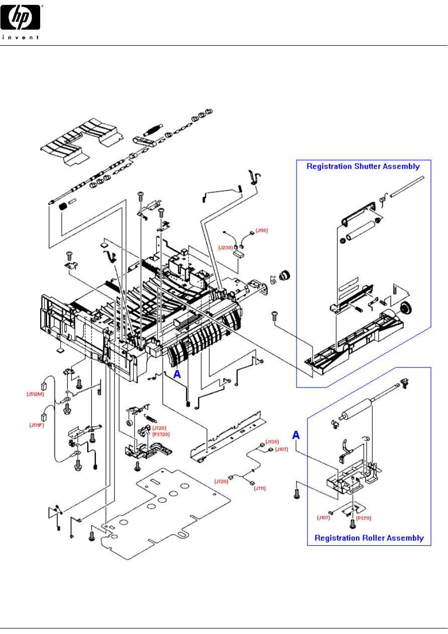
Roller Assembly
211
RF5-4040-020CN
Transfer roller assembly - Long black foam type roller - Transfers static charge to paper - Mounts towards the front
and on top of the middle frame assembly
212
RG5-6897-000CN
Upper top bin output roller assembly - Includes the shaft with four rubber rollers, two bushing/shaft retainers, two
anti-reversing flaps, and the drive gear - Mounts on the top rear of the printer
213
RG5-6936-000CN
Lower top bin output roller assembly - Includes the shaft with four rubber rollers, two bushing/shaft retainers, and the
drive gear - Mounts in the center on the rear frame assembly (above the fusing assembly)
214
RG5-6939-000CN
Registration roller assembly - Includes the roller, bushings, mounting plate, paper sensor, and the sensor flag -
Mounts from the bottom toward the front center of the middle frame assembly
215
RG5-6952-000CN
Paper pick-up roller assembly - Includes the shaft, guide assembly cams, the D-shaped roller, and roller retainers -
Picks paper from the multi-purpose front input tray (tray 1) - Mounts in the lower portion of the front frame assembly
Shaft
216
RB3-0011-000CN
Feed drive shaft - Long shaft with eight feed belt ball type pulleys and one ribbed feed guide drive belt pulley -
Mounts behind the transfer roller on the middle frame assembly
Shutter
217
RG5-6940-000CN
Registration shutter assembly - Includes the metal roller, mounting frame, grounding springs, and the dual coupling
gear - Mounts over the registration roller at the front of the middle frame assembly
Spring
218
RB2-9905-000CN
Torsion spring - Provides pressure for the upper top bin output pressure rollers (two used)
219
RB2-9906-000CN
Torsion spring - Provides pressure for the lower top bin output pressure rollers (two used)
220
RB2-9952-000CN
Tray 1 flag spring - Provides torsion for the tray 1 paper sensor flag - Mounts in the lower portion of the front frame
assembly
221
RB3-0015-000CN
Compression spring - Provides upward pressure for the left bushing on the transfer roller assembly
222
RB3-0016-000CN
Electrical contact spring - Spring steel wire with compression springs formed on both ends - One end provides
upward pressure on the right bushing for the transfer roller - Connects to high voltage board
Static Dissipater
223
RB3-0009-000CN
Static eliminator ground plate - Right angled metal piece with small teeth on top edge - Mounts from underneath on
the middle frame assembly just behind the pulley rollers
Tray 2 Assembly Parts
Body
224
RG5-6915-030CN
250 sheet cassette tray main body assembly - Includes the main structure frame, paper stops, lift plate, springs, and
the separation pad assembly - Does NOT include the blue plastic front cover - For the cassette on the 250 sheet
input tray assembly
Bushing
225
RB2-2895-000CN
Shaft bushing/retainer - Pickup roller support bushing on right side - Mounts on and retains the right end of the pick-
up roller shaft - For the base on the 250 sheet input tray assembly
226
RB2-2896-000CN
Shaft bushing/retainer - Pickup roller support bushing on left side - Mounts on and retains the left end of the pick-up
roller shaft - For the base on the 250 sheet input tray assembly
227
RB2-2897-000CN
Shaft bushing/retainer - Mounts on the gear side of the drive shaft for the paper pick-up roller assembly - For the
base on the 250 sheet input tray assembly
228
RS5-1636-000CN
Shaft bushing - Mounts on the gear end of the feed roller shaft in the base on the 250 sheet input tray assembly
229
RS5-1638-000CN
Bushing - For the registration roller gear drive shaft on the right side of the front frame assembly, and the left side of
the feed roller in the 250 sheet paper input tray assembly
Cable
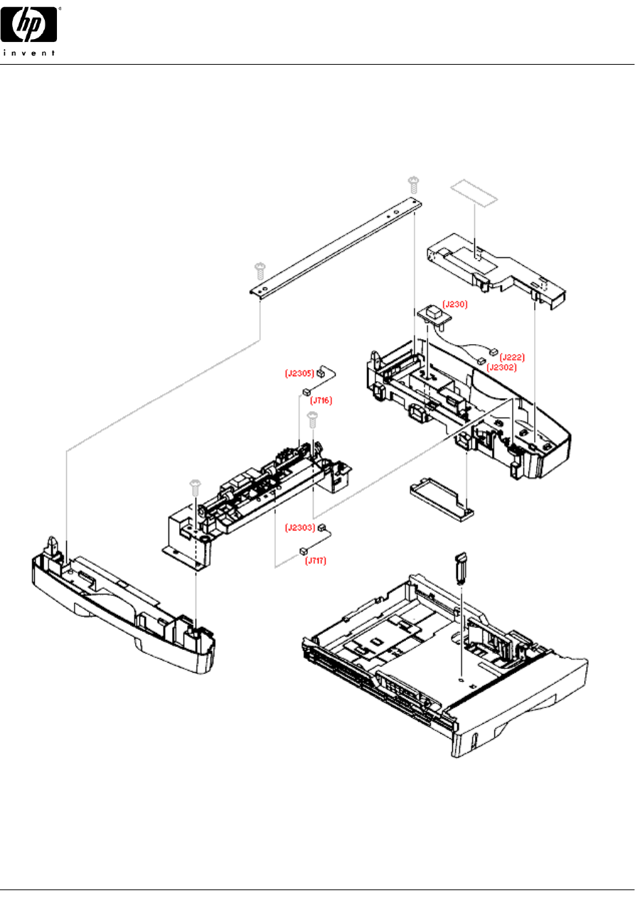
230
RG5-7138-000CN
Cable assembly - From the sensor (PS717) (which senses paper feeding from optional tray 3) to the small
interconnecting PC board on the right side frame/cover assembly - For the base on the 250 sheet input tray
assembly
231
RG5-7139-000CN
Cable assembly - From the paper out sensor (PS716) to the small interconnecting PC board on the right side
frame/cover assembly - For the base on the 250 sheet input tray assembly
232
RG5-7149-000CN
Connector assembly - Includes the 14 pin (F) interface connector and cable assembly - (Tray 2 to printer connector)
Connects to the feed drive PC board in the cassette base assembly
Clip
233
XD9-0136-000CN
Retaining E-ring - Mounts on the left end of the paper feed roller assembly - For the base on the 250 sheet input tray
assembly
© 2004 Hewlett-Packard
10

HP Color LaserJet 2500 printer
HP Parts Reference Guide™
www.hp.com/go/hpparts
Tray 2 Assembly Parts
Connector
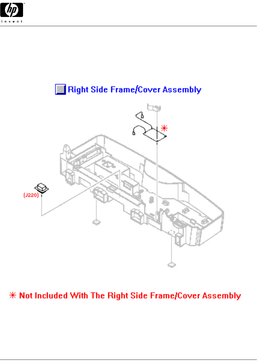
234
RH2-5519-000CN
Connector assembly - For optional paper tray - One mounts to the bottom right side of the printer middle frame
assembly (Interfaces 250 sheet tray), and the other to the bottom of the 250 sheet tray base assembly (Interfaces
500 sheet tray) - (2 used)
Cover
235
RB3-0106-000CN
Left side frame/cover (Quartz Gray plastic) - Left side cover and paper tray guide - For the base on the 250 sheet
input tray assembly
236
RB3-0109-000CN
Front cover for the 250 sheet paper cassette tray (blue plastic) - Has molded in paper loading instructions and a "2"
on the front - For the cassette on the 250 sheet input tray assembly
237
RB3-0165-000CN
Top inner cover (black plastic) - Covers the back half of the pressure roller arms and springs - For the base on the
250 sheet input tray assembly
238
RB3-0166-000CN
Bottom inner cover (black plastic) - Mounts on the bottom of the center frame assembly in the base on the 250 sheet
input tray assembly - One covers the paper feed sensor in the center and the other covers sensor wires toward the
right side (2 used)
239
RB3-0282-000CN
Inner cover - Covers the small interconnecting PC board and the connector for tray 3 - Mounts on top of the right
side support frame/cover assembly - For the base on the 250 sheet input tray assembly
240
RB3-0283-000CN
Inner cover - Covers the connector that interconnects the input tray base to the printer - Mounts on the bottom of the
right side support frame/cover assembly - For the base on the 250 sheet input tray assembly
241
RG5-6919-000CN
Right side frame/cover assembly (Quartz Gray plastic) - Includes the right side cover and paper tray guide, the
cassette retainer spring, tray 3 connector, printer interface connector, and rubber feet - For the base on the 250
sheet input tray assembly
Cross-Brace
242
RB3-0108-000CN
Metal support cross-brace - Mounts on the top rear of the left and right support frame/cover assemblies - For the
base on the 250 sheet input tray assembly
Flag
243
RB3-0130-000CN
Shaft mounted sensor flag (black plastic) - For the paper out sensor - Mounts on the paper pick-up roller drive shaft -
For the base on the 250 sheet input tray assembly
244
RB3-0132-000CN
Mechanical sensor flag (black plastic) - For the paper feed sensor - Mounts on top of the center frame assembly -
For the base on the 250 sheet input tray assembly
Frame
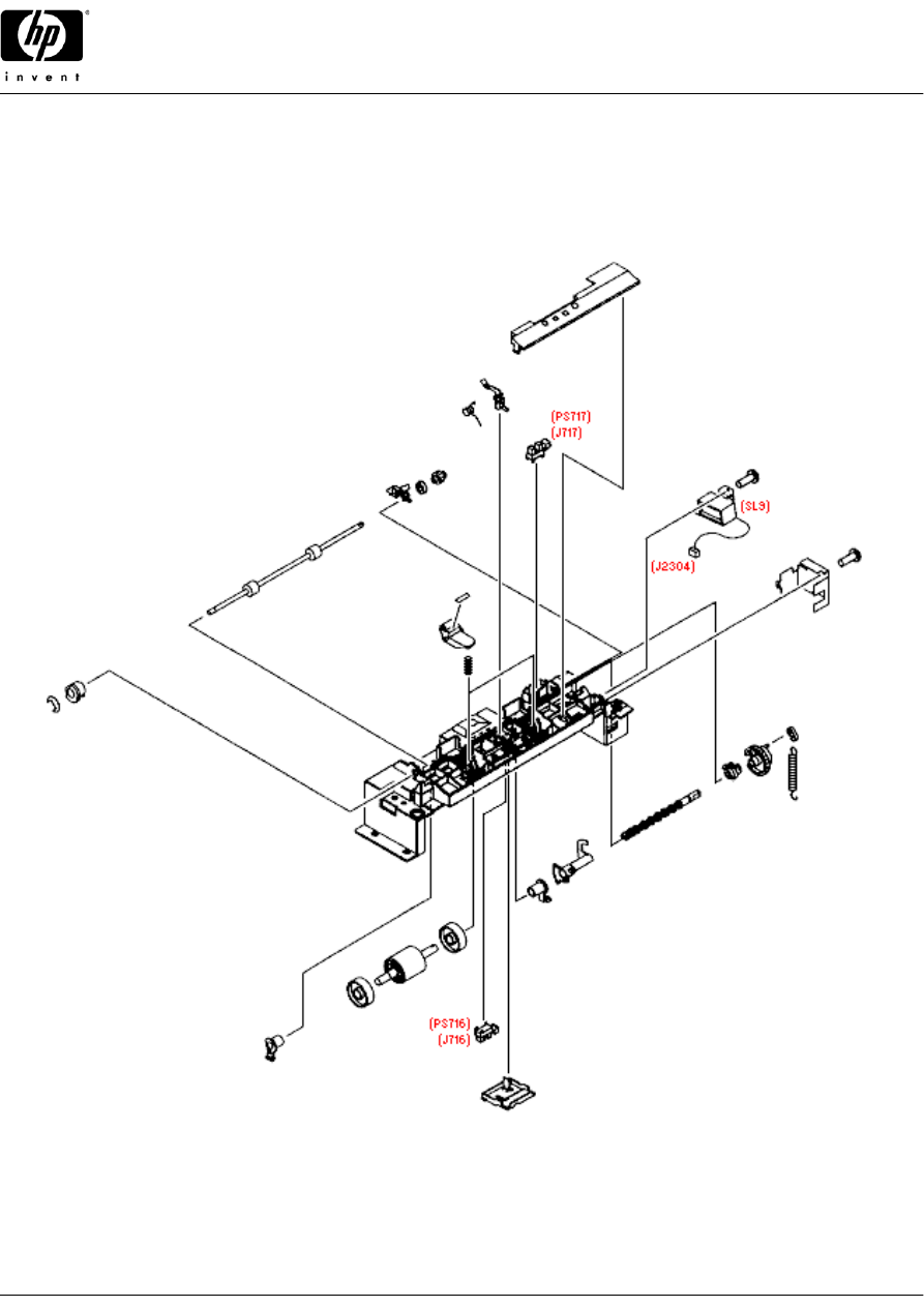
245
RB3-0105-000CN
Center support frame (black plastic) - Support structure for the paper pick-up roller, feed roller, and paper sensors -
Mounts to the top front of both of the support frame/cover assemblies on the base of the 250 sheet input tray
assembly
Gear
246
RS7-0430-000CN
26 tooth gear - White gear with 1/8th portion of gear cut away and pin for spring tensioning - Mounts on the end of
the paper pick-up roller in the base on the 250 sheet input tray assembly
247
RS7-0431-000CN
15 tooth Gear (white plastic) - Mounts on the end of the feed roller shaft in the base on the 250 sheet input tray
assembly
Ground Plane
248
RB3-0137-000CN
Grounding plate - Grounds the paper feed roller - Mounts towards the right end of the center frame assembly - For
the base on the 250 sheet input tray assembly
Hook
249
RB1-2190-000CN
Pick-up roller spring hook - Clips on the pin of the drive gear for the pick-up roller and hooks the tensioning spring -
For the base on the 250 sheet input tray assembly
PC Board
251
RG5-6968-000CN
Interconnecting feed drive PC board - Mounts in the right side cover assembly - For the base on the 250 sheet input
tray assembly
252
WG8-5382-000CN
Sensor PC board - Small board with flag activated photosensor - (PS718) Paper sensor for the multi-purpose tray,
(PS720) fusing assembly front of page sensor, and (PS716/PS717) paper feed/out sensors in the 250 sheet tray
assembly (four used)
Pad
250
RF5-4258-000CN
Separation pad assembly - Includes the gray plastic frame with the rubber insert strip - For the cassette on the 250
sheet input tray assembly
© 2004 Hewlett-Packard
11

HP Color LaserJet 2500 printer
HP Parts Reference Guide™
www.hp.com/go/hpparts
Tray 2 Assembly Parts
Roller
253
RB2-2892-000CN
Guide roller (Free spinning white plastic roller) - One on each side of the rubber paper pick-up roller - For the base
on the 250 sheet input tray assembly
Roller Assembly
254
RB3-0129-000CN
Feed roller assembly - Includes the metal shaft and two small rubber rollers - Feeds paper from the paper cassette
(or tray 3 below) into the printer - Mounts on the top of the center frame in the base on the 250 sheet input tray
assembly
255
RB3-0161-000CN
Paper pick-up roller assembly - Includes the 'D' shaped rubber roller on a plastic shaft - Mounts in the lower center
of the center frame assembly - For the base on the 250 sheet input tray assembly
256
RF5-4035-000CN
Pressure roller and arm assembly - Includes the small white roller, the holding arm, and roller scraper - Rolls against
the rubber feed rollers (2 used) - For the base on the 250 sheet input tray assembly
Shield
257
RB3-0136-000CN
Solenoid cover/magnetic shield - Mounts on the right end of the center frame assembly (over the pick-up solenoid) -
For the base on the 250 sheet input tray assembly
Solenoid
258
RH7-5341-000CN
Solenoid assembly - (SL9) Lever on the solenoid disengages the stop on the drive gear on the paper pick-up roller -
For the base on the 250 sheet input tray assembly
Spring
259
RB2-2843-000CN
Torsion spring - Provides a small amount of back pressure for the paper sensor flag - For the base on the 250 sheet
input tray assembly
260
RS6-2025-000CN
Tensioning spring - Goes between the hook on the pin on the paper pick-up roller drive gear and a pin on the center
frame assembly - For the base on the 250 sheet input tray assembly
261
RS6-2760-000CN
Compression spring - Provides pressure for the pressure rollers on the center frame assembly (2 used) - For the
base on the 250 sheet input tray assembly
Stop
262
RB2-3019-000CN
Shipping stopper (bright orange plastic) - Helps to prevent damage to the paper tray by restricting the movement of
the lift plate (Removed for normal use) - For the cassette on the 250 sheet input tray assembly
Support
263
RB2-9963-000CN
Separation pad support - Pivoting 'L' shaped metal support frame (Does NOT include the separation pad assembly)
- For the cassette on the 250 sheet input tray assembly
Tray Assembly
264
RG5-6914-030CN
250 sheet paper tray assembly - Pull out cassette that the paper is loaded into - Does NOT include the paper feed
base assembly - The cassette on the lower 250 sheet input tray assembly
© 2004 Hewlett-Packard
12
HP Color LaserJet 2500 printer
HP Parts Reference Guide™
www.hp.com/go/hpparts
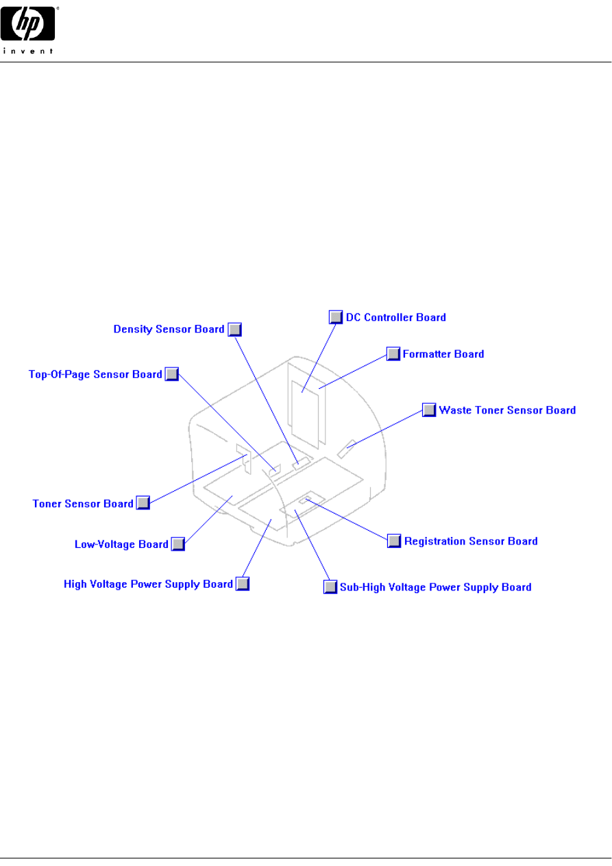
PC Board Assembly Locator
_
54
_
50
_
71, 72
_
69
_
53
_
55
_
56
_
51
_
70
_
49
© 2004 Hewlett-Packard
13
HP Color LaserJet 2500 printer
HP Parts Reference Guide™
www.hp.com/go/hpparts
External Covers
\
91
\
89
\
92
/
99
/
90
\
107
\
105
/
88
|
100
/
98
© 2004 Hewlett-Packard
14
HP Color LaserJet 2500 printer
HP Parts Reference Guide™
www.hp.com/go/hpparts
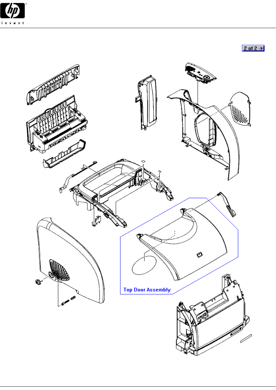
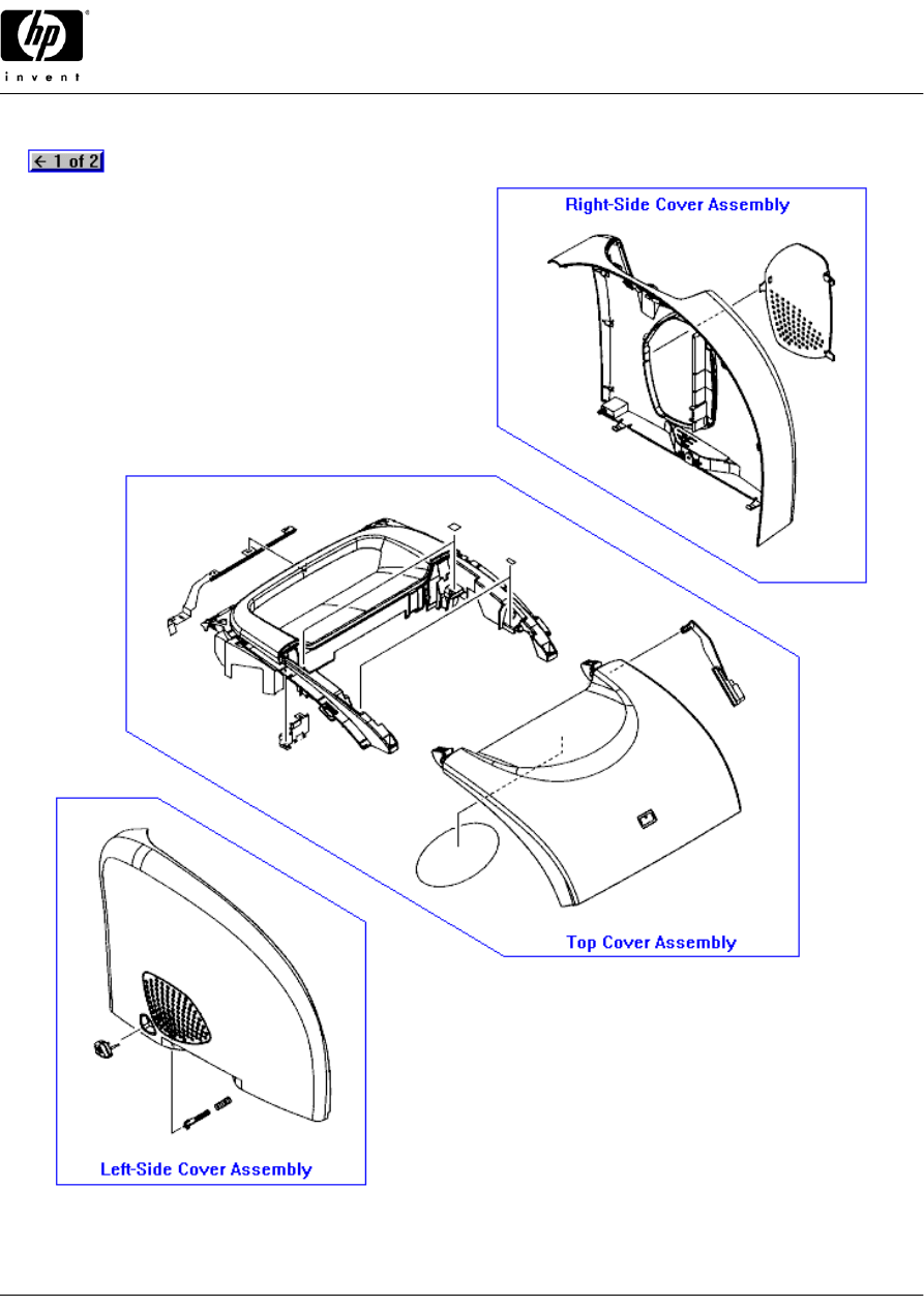
External Covers (Assemblies)
|
95
|
96
|
97
© 2004 Hewlett-Packard
15
HP Color LaserJet 2500 printer
HP Parts Reference Guide™
www.hp.com/go/hpparts
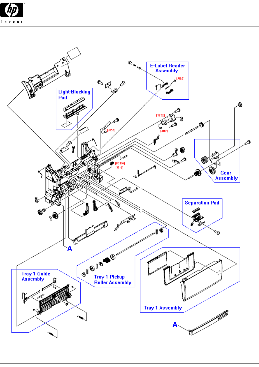
Front Frame Assembly
\
220
\
188
\
189
\
194
\
195
\
146
\
93
\
94
\
144
\
200
\
41, 163
\
37, 145
|
181
/
148
/
182
\
76
|
202
/
190
/
190
\
152
\
153
|
155
\
157
|
191
\
52, 252
|
161
|
187
|
210, 215
/
140
|
73, 74
/
154
/
136
|
173
\
166
\
103
\
40, 162
|
138, 229
\
167
/
142
|
54
\
56
© 2004 Hewlett-Packard
16
HP Color LaserJet 2500 printer
HP Parts Reference Guide™
www.hp.com/go/hpparts
Internal Components (1 of 2)
/
186
/
178
\
133
\
150
\
151
|
201
\
39
|
211
\
87
\
30
/
31
\
196
\
221
\
158
\
159
\
160
/
218
/
207
|
212
\
47
© 2004 Hewlett-Packard
17
HP Color LaserJet 2500 printer
HP Parts Reference Guide™
www.hp.com/go/hpparts
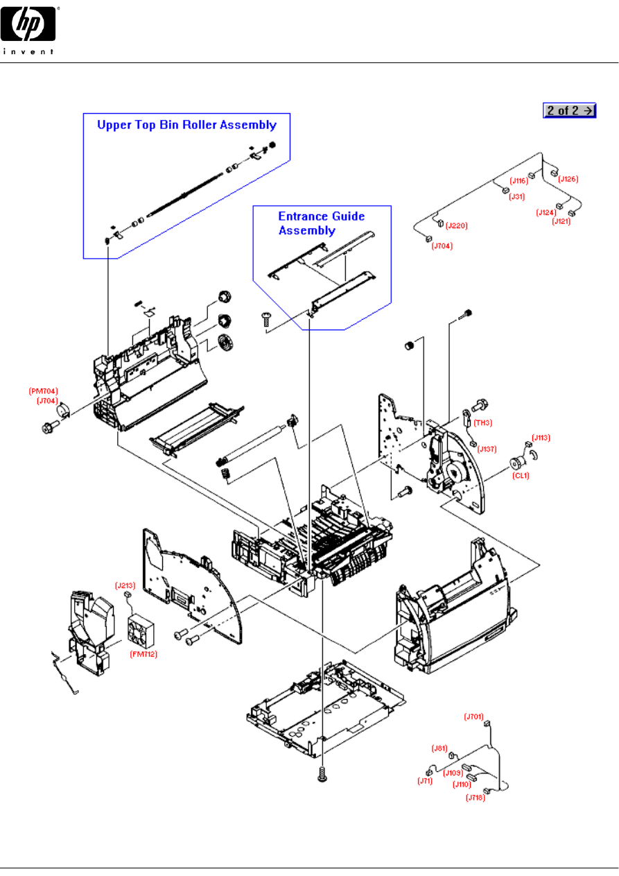
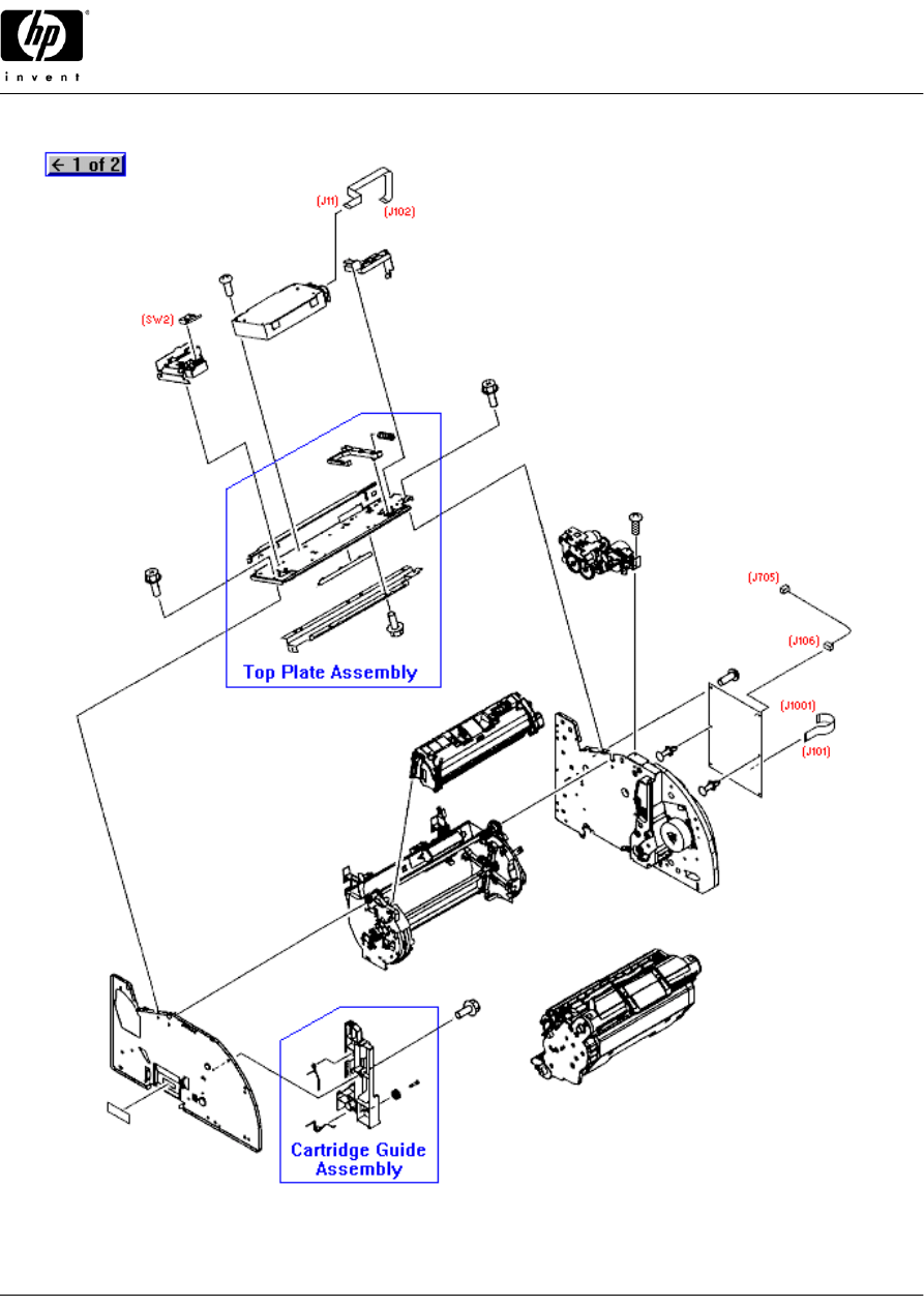
Internal Components (2 of 2)
\
33
/
170
|
185
\
164
\
43
/
21
\
14
\
86
|
168
\
125, 126, 197, 198
|
116, 117, 118, 119,
120, 121, 122, 123
\
50
© 2004 Hewlett-Packard
18
HP Color LaserJet 2500 printer
HP Parts Reference Guide™
www.hp.com/go/hpparts
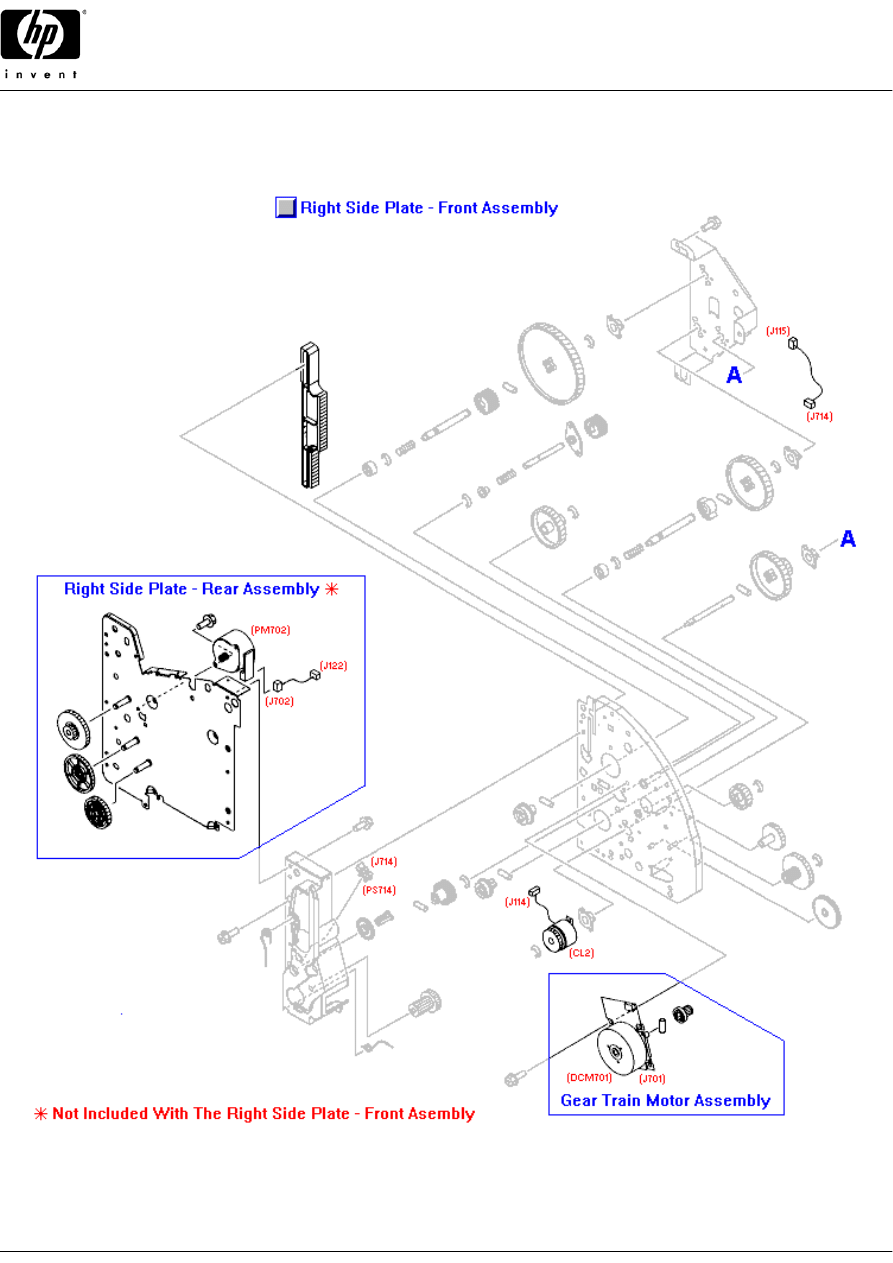
Main Drive Assembly
_
179
|
45
_
34
/
176
/
22
|
180
© 2004 Hewlett-Packard
19
HP Color LaserJet 2500 printer
HP Parts Reference Guide™
www.hp.com/go/hpparts
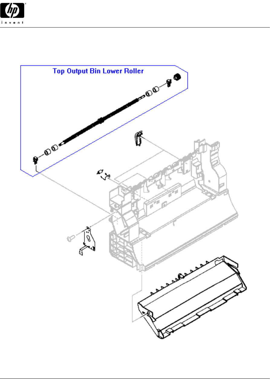
Rear Frame Assembly
\
132
|
213
/
219
/
208
|
174
/
165
© 2004 Hewlett-Packard
20
HP Color LaserJet 2500 printer
HP Parts Reference Guide™
www.hp.com/go/hpparts
Middle Frame Assembly
\
192
\
204
\
204
\
193
\
193
\
193
\
193
\
193
\
193
\
193
\
193
_
101
|
60
\
223
\
203
\
216
\
209
\
177
|
82
|
78, 222
\
149
|
79
\
80
/
81
\
83
/
84
/
85
\
137
\
42, 172
/
57
_
101
\
35, 234
\
156
|
214
|
25
|
217
|
24
/
143
/
57
/
58
|
147, 199
/
169
/
206
\
205
\
205
\
27
_
52, 252
/
183
/
29
© 2004 Hewlett-Packard
21
HP Color LaserJet 2500 printer
HP Parts Reference Guide™
www.hp.com/go/hpparts
Toner Cartridge Carousel Assembly
|
16, 74
|
75
|
175
_
23
/
28
_
139
/
134
\
135
© 2004 Hewlett-Packard
22
HP Color LaserJet 2500 printer
HP Parts Reference Guide™
www.hp.com/go/hpparts
Toner Cartridge Carousel Drive Assembly
_
38
\
46
\
48
/
77
© 2004 Hewlett-Packard
23
HP Color LaserJet 2500 printer
HP Parts Reference Guide™
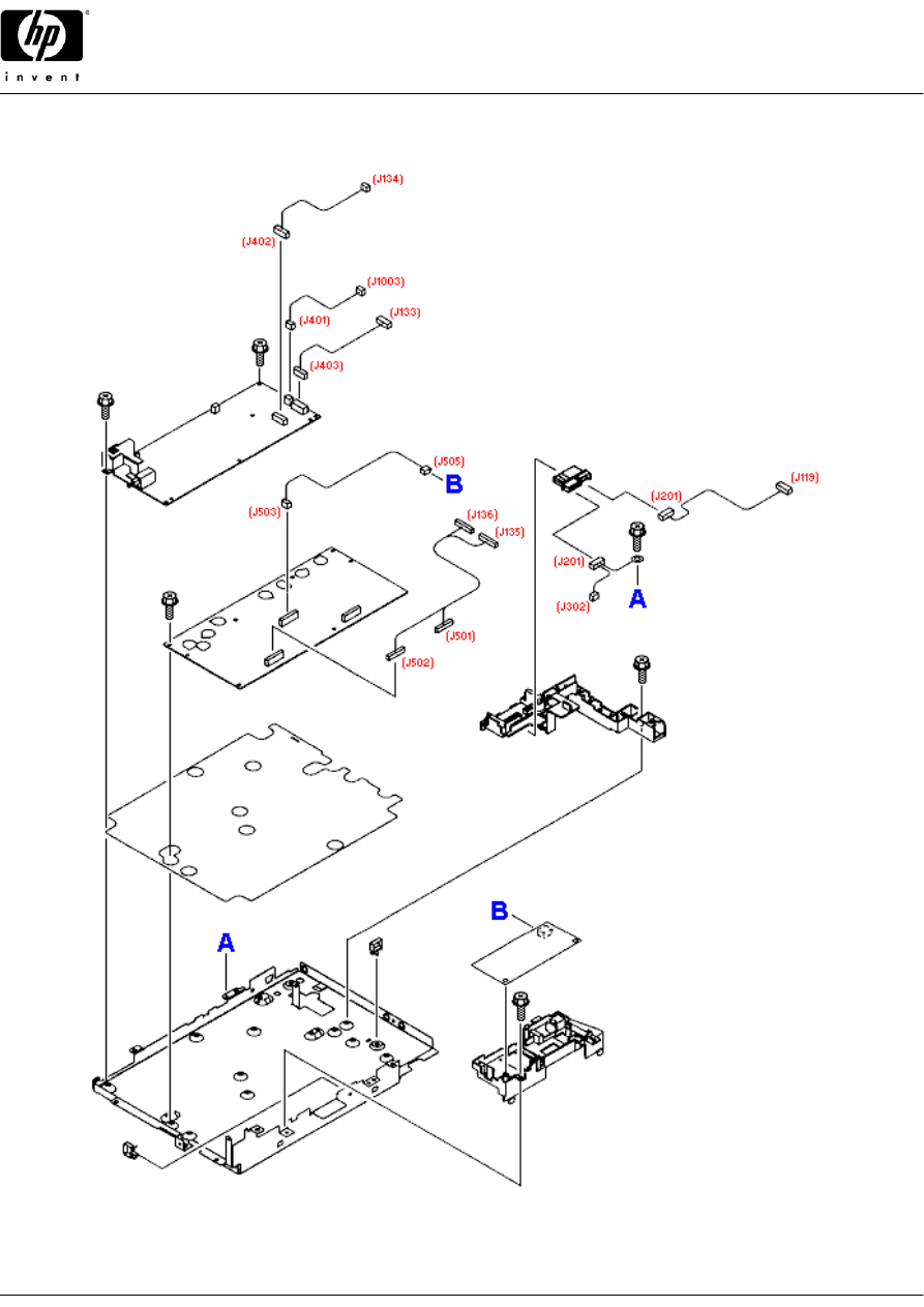
www.hp.com/go/hpparts
Power Supply Base Assembly
\
102
\
171
/
36
\
32
/
141
\
26
|
20
|
15
|
17
\
18
\
19
\
177
\
71, 72
\
69
\
70
© 2004 Hewlett-Packard
24
HP Color LaserJet 2500 printer
HP Parts Reference Guide™
www.hp.com/go/hpparts
Fusing Assembly
_
111, 112
\
110
\
110
|
106, 115
|
106, 115
|
104
|
44
|
113
|
108, 109
|
114
© 2004 Hewlett-Packard
25
HP Color LaserJet 2500 printer
HP Parts Reference Guide™
www.hp.com/go/hpparts
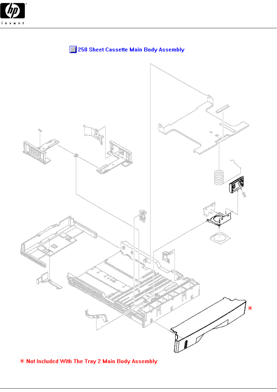
250 Sheet Tray - External Covers
/
235
\
242
/
239
/
240
_
262
\
231
\
230
_
232
© 2004 Hewlett-Packard
26
HP Color LaserJet 2500 printer
HP Parts Reference Guide™
www.hp.com/go/hpparts
250 Sheet Tray - Center Frame Assembly
/
249
\
245
\
237
/
238
\
247
|
246
_
261
_
260
\
228
\
259
|
253
|
253
\
225
\
226
|
227
\
138, 229
\
254
/
52, 252
/
52, 252
\
243
\
244
|
257
\
248
\
255
\
256
\
258
\
233
© 2004 Hewlett-Packard
27
HP Color LaserJet 2500 printer
HP Parts Reference Guide™
www.hp.com/go/hpparts
250 Sheet Tray - Right Cover Assembly
_
241
\
251
\
35, 234
© 2004 Hewlett-Packard
28
HP Color LaserJet 2500 printer
HP Parts Reference Guide™
www.hp.com/go/hpparts
250 Sheet Tray - Paper Cassette Tray
_
224, 264
\
236
/
250
\
263
© 2004 Hewlett-Packard
29

HP Color LaserJet 2500 printer
HP Parts Reference Guide™
www.hp.com/go/hpparts
HP Parts Reference Guide
http://www.hp.com/go/parts
HP PartSurfer
http://partsurfer.hp.com
HP Parts Ordering Information
http://www.hp.com/go/hpparts
HP Parts Questions/Comments
http://partsurfer.hp.com/contactus.htm
© 2004 Hewlett-Packard
30
Wyszukiwarka
Podobne podstrony:
instrukcja obsługi HP LASERJET 4L ML O
HP LaserJet Companion Service Manual
HP LaserJet 4600 Service Manual Update
HP LaserJet 1000w Tiskarna
HP LaserJet 8000DN
HP LaserJet Companion Printer Service Manual
HP LaserJet 4200DTN
hp laserjet 4si
HP LaserJet 4200
HP LaserJet 2300
HP LaserJet 2100
HP LaserJet 2300D
HP LaserJet 4000
HP LaserJet 4100
HP LaserJet 3330MFP Fax Guide
HP LaserJet 45xx Service Manual Update Mar03
HP LaserJet 4050N
PIN Codes for HP LaserJet Service Menu
więcej podobnych podstron