
1
Special Report
Precast Prestressed Concrete
Horizontally Curved
Bridge Beams
prepared by
ABAM Engineers
A MEMBER OF THE BERGER GROUP
33301 Ninth Avenue South
Federal Way, Washington 98003-6395

2
Substantial effort has been made to ensure that all data and infor-
mation in this report are accurate. However, PCI cannot accept
responsibility for any errors or oversights in the use of material or
in the preparation of engineering plans. This publication is
intended for use by professional personnel competent to evaluate
the significance and limitations of its contents and able to accept
responsibility for the application of the material it contains.
Special conditions on a project may require more specific evalu-
ation and practical engineering judgment.
JR 350-88
Copyright © 1988
Prestressed Concrete Institute
All rights reserved. This report or any part thereof may not
be reproduced in any form without the written permission
of the Prestressed Concrete. Institute.

3
CONTENTS
1. Introduction ................................................................................4
2. Concept Description...................................................................4
3 Cost Comparisons .....................................................................6
4. Analysis and Design .................................................................7
5. Design Alternatives ...................................................................9
6. Fabrication Techniques ............................................................10
7. Conclusion ...............................................................................10
Reference .....................................................................................11
Appendix A – Conceptual Drawings and Details..........................11
Appendix B – Design Charts........................................................19
Appendix C – Design Example ....................................................33
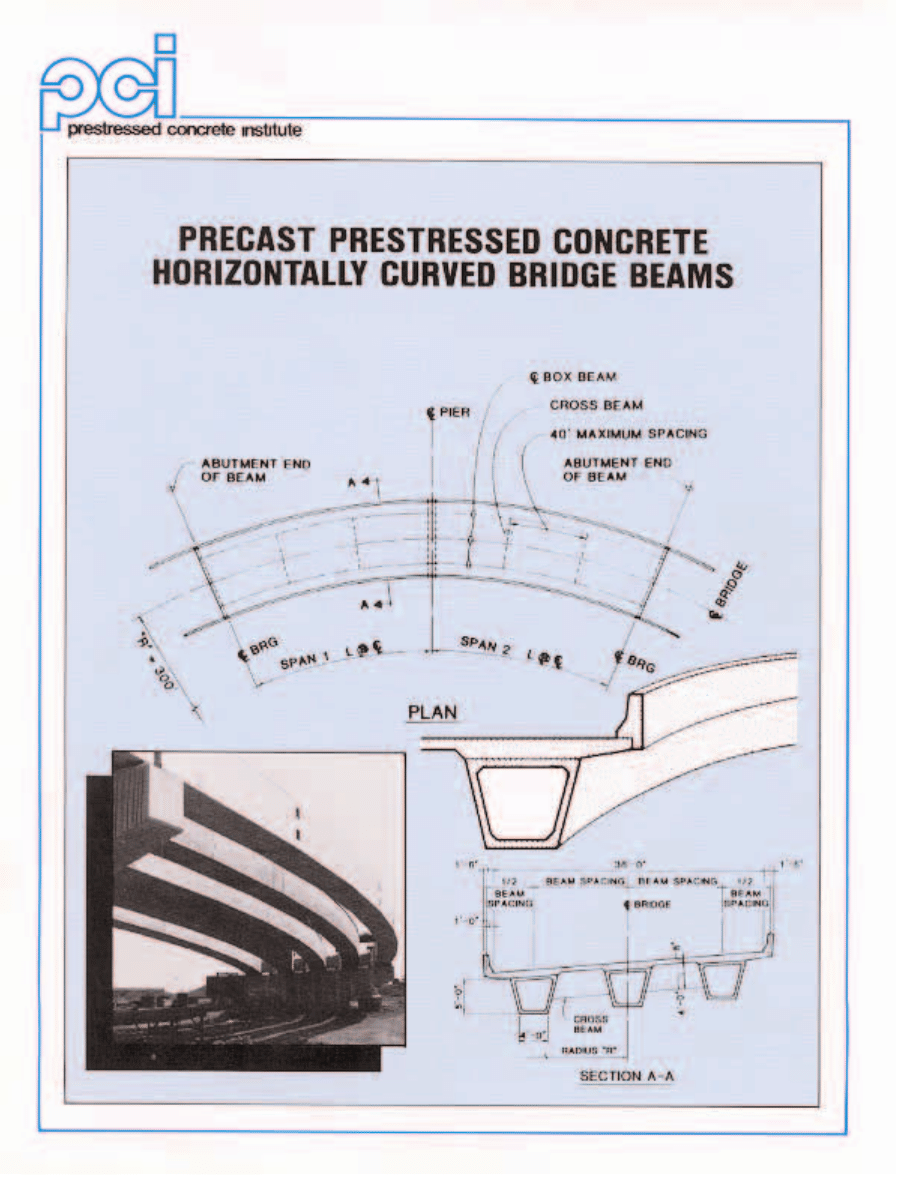
This report discusses the concept, analysis and
design procedures, design alternatives and fabrication
techniques recommended for precast prestressed
horizontally curved bridge beams. Comparisons of
curved precast bridge superstructures with steel and
cast-in-place concrete demonstrate the aesthetic and
economic advantages a precast concrete solution
offers to bridge owners and engineers. Three sepa-
rate appendixes contain plans and details, design
charts and a design example applying the design
aids.
4
New interchanges off limited access
highways often require horizontally
curved medium length bridge beams.
These bridge beams have been made
almost exclusively of steel where false-
work restrictions preclude cast-in-place
concrete construction. This report presents
results of a project sponsored by the
Prestressed Concrete Institute (PCI) to
develop standards for precast prestressed
horizontally curved bridge beams.
The idea to develop horizontally curved
bridge beams won PCI’s Industry
Advancement Award in 1985. This award
winning idea was developed from a pre-
cast prestressed curved beam project con-
structed in Pennsylvania. PCI subsequent-
ly issued a request for proposals to devel-
op this idea. ABAM Engineers of Federal
Way, Washington, was selected to pursue
this effort.
This report summarizes the concept,
analysis and design procedures, and fabri-
cation techniques recommended for pre-
cast prestressed horizontally curved bridge
beams. Comparisons of curved precast
bridge superstructures with steel and
cast-in-place concrete demonstrate the
aesthetic and economic advantages a pre-
cast concrete solution offers to bridge
owners and design engineers.
1. INTRODUCTION
A concept for horizontally curved pre-
cast prestressed concrete beams is pre-
sented. The concept uses the basic idea
that won PCI’s Industry Advancement
Award for 1985. Several alternatives to
this basic idea for materials, fabrication
and erection procedures, beam geometry,
and beam cross sections were evaluated.
Descriptions of these alternatives are
listed in Table 1. Concept 8, a trape-
zoidal box beam, was selected for devel-
opment in this report. Design charts and
conceptual drawings are presented for 5
and 6 ft (1.52 and 1.83 m) deep precast
box beams. These charts are intended to
present preliminary prestressing strand
and concrete strength criteria for various
spans and beam spacings. Appendix A
contains conceptual design plans and
details.
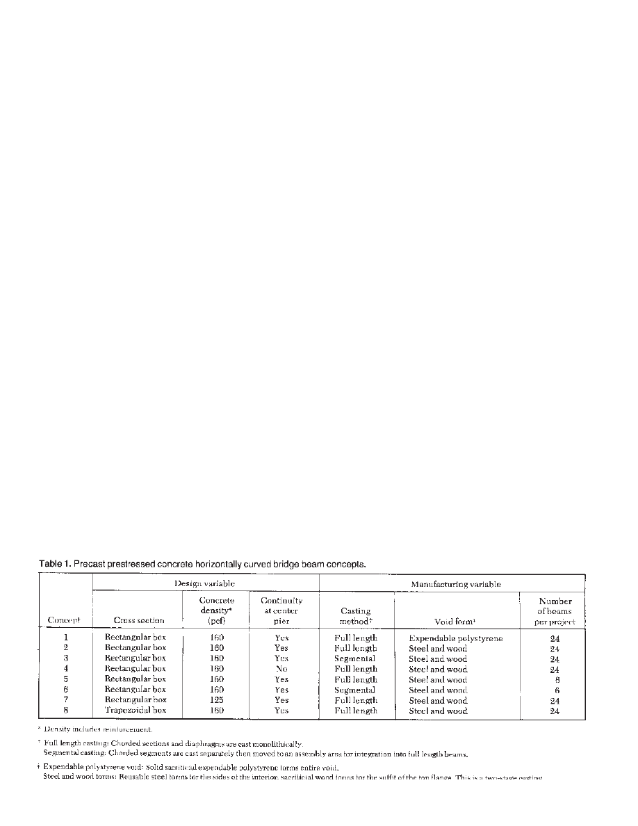
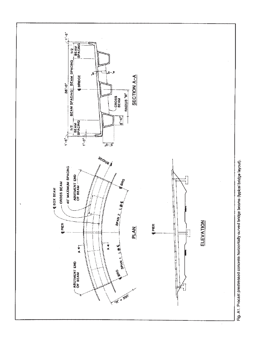
The concept uses long precast concrete
beams spanning between supports.
Chorded sections [20 ft (6.10 m) long]
are used to approximate curved geome-
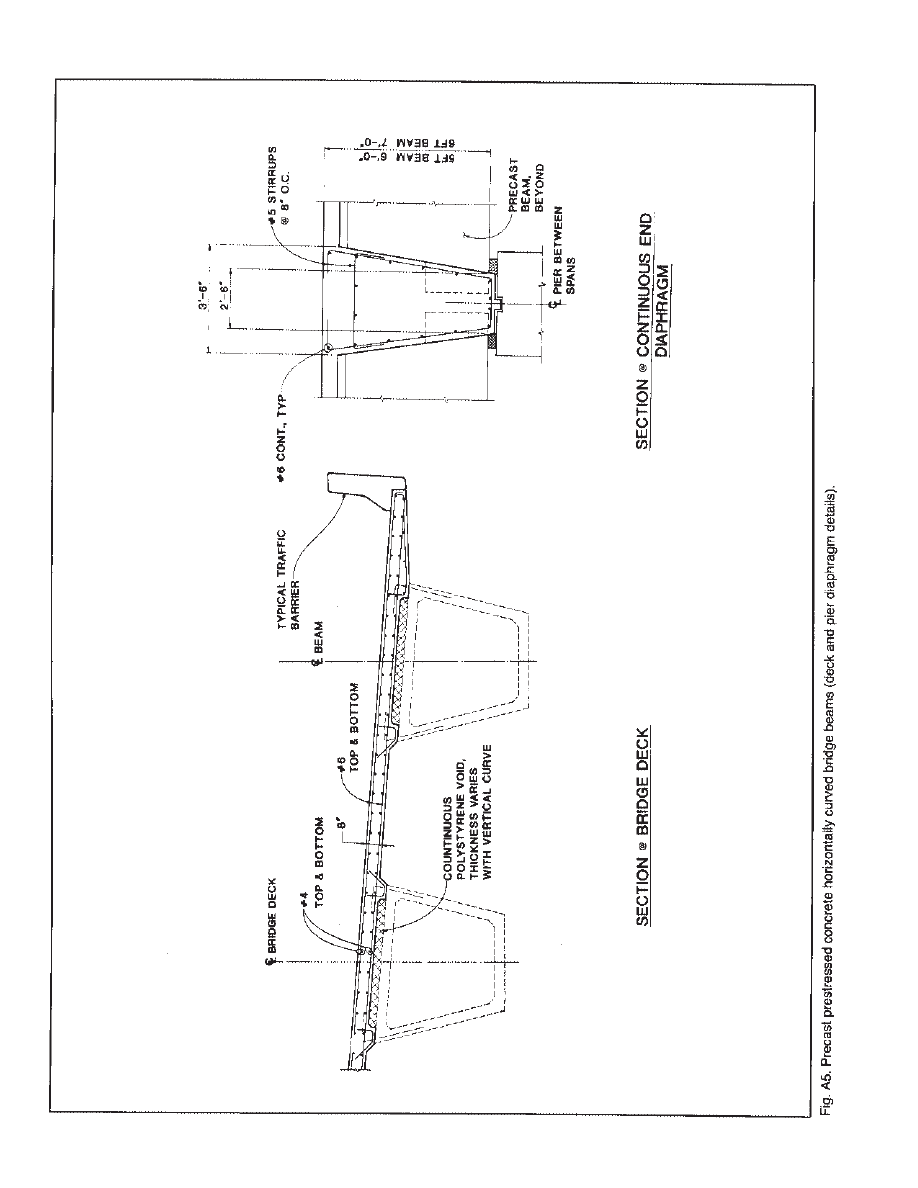
try (Figs. 1 and 2). Diaphragms are pro-
vided at angle points between these
chorded sections. This chord length pro-
duces a 2 in. (51 mm) offset on a 300 ft
(91.5 m) radius curve. The beams are
chorded in plan and in profile. Individual
precast beams are post- tensioned togeth-
er in the field to form continuous struc-
tures.
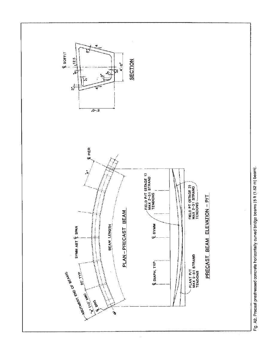
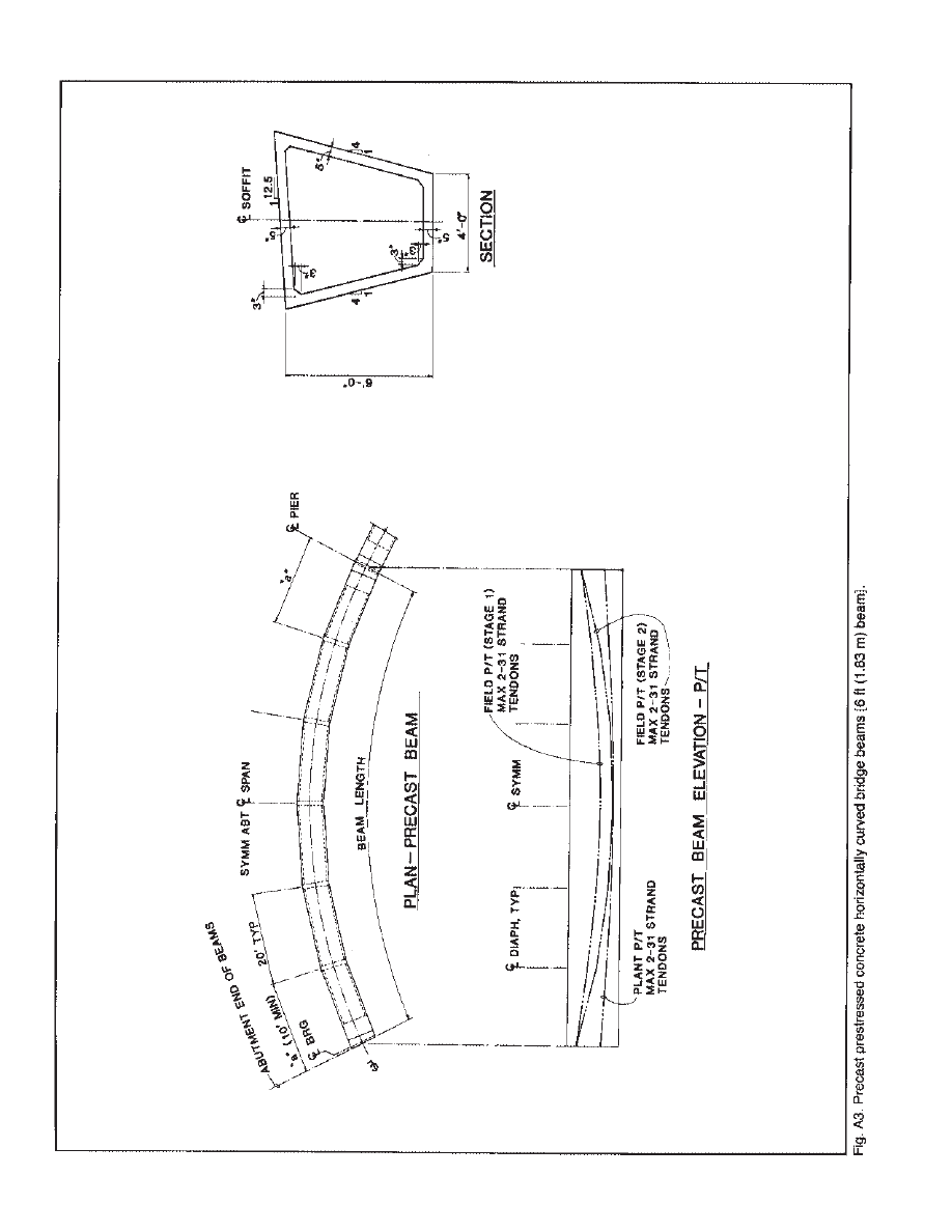
Trapezoidal box beams are used to
produce a torsionally rigid section that is
aesthetically pleasing (Fig. 3). Span to
depth ratios for bridge superstructures
constructed with 5 ft (1.52 m) deep pre-
cast box beam elements can be 27 to 1
for interior spans and 23 to 1 for exterior
spans. These span to depth ratios are
comparable to bridges constructed from
composite welded steel girders and from
cast-in-place post-tensioned box girders.
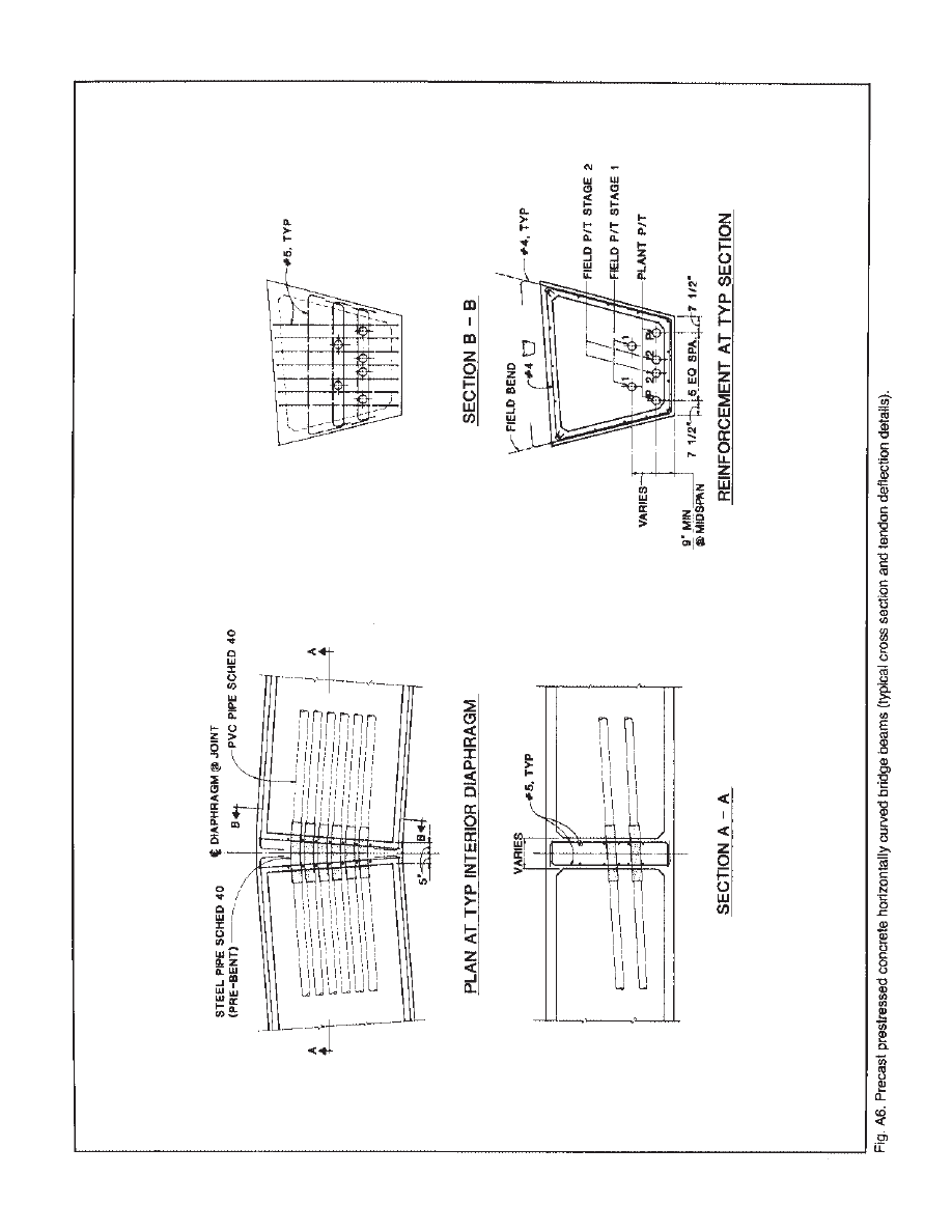
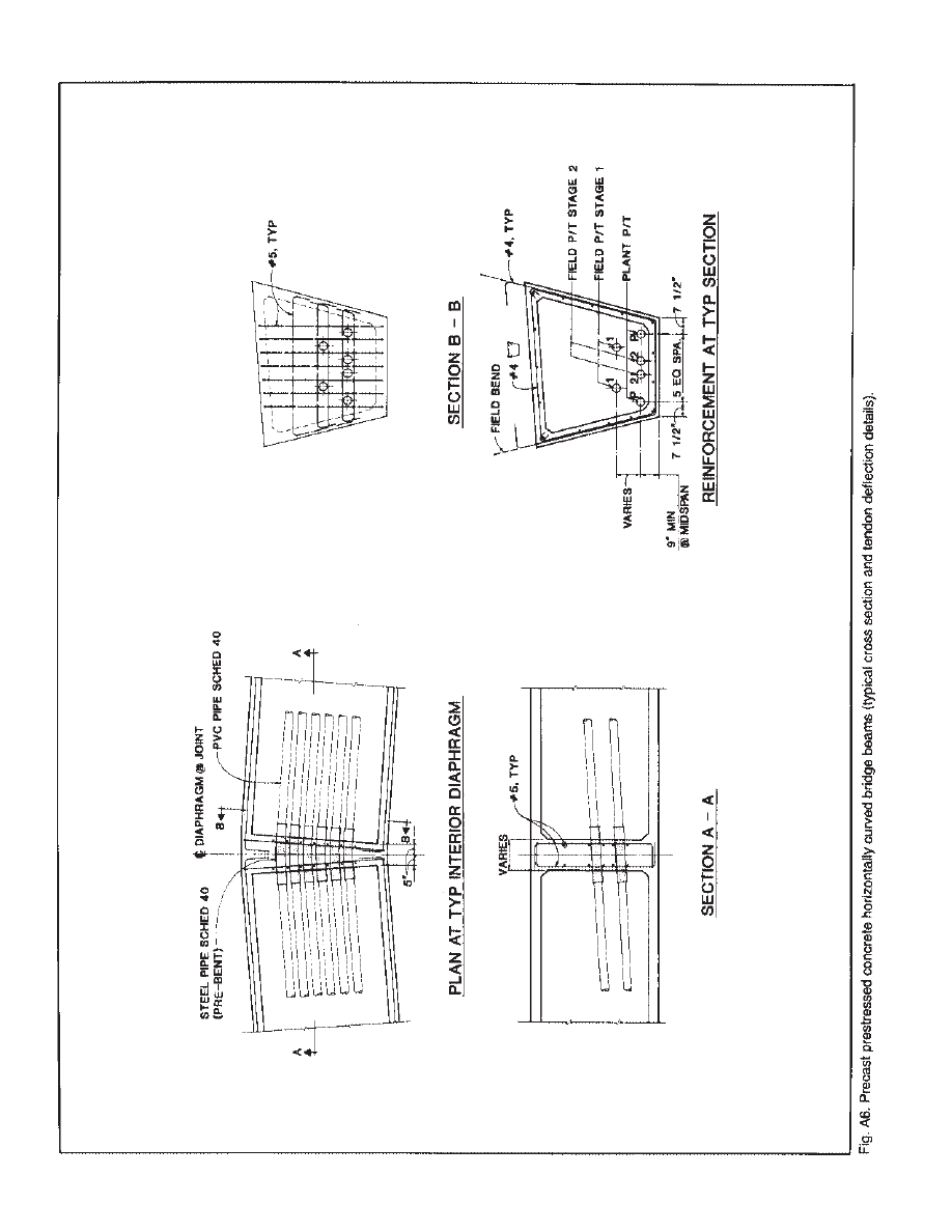
Post-tensioning tendons are placed
inside the beam void and are deflected
horizontally and vertically at diaphragms
between chorded sections. The tendons,
therefore, form a string polygon that
approximates a parabolic shape in profile
and the curve radius in plan (Fig. 4).
Tendons are bonded to the cross section
at each diaphragm but are not continu-
ously bonded along the tendon length.
The concept allows individual beam
lines to be bent horizontally to specific
design radii and to provide different pro-
files for individual beam lines to build in
vertical curves and varying supereleva-
tions. A table of precast beam geometry
would be developed for each project.
Construction of a bridge made from
precast prestressed horizontally curved-
2. CONCEPT DESCRIPTION
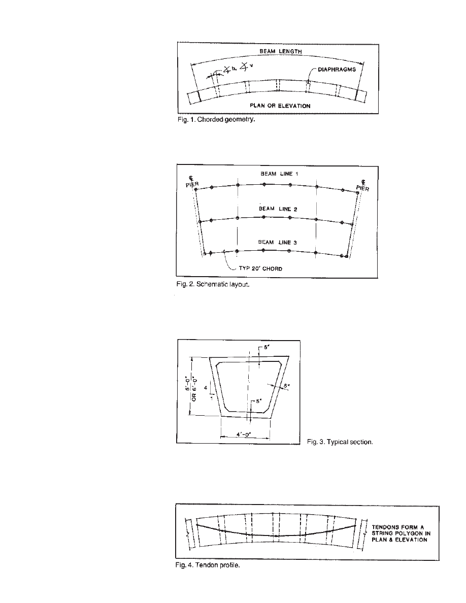
beams involves three basic steps, illus-
trated in Figs. 5, 6 and 7.
■ Step 1 (Fig. 5): Beams are fabricated
full length in the plant in specially
designed formwork. Beams are cast in
two stages. Stage 1 includes the soffit and
webs of the chorded sections, end
diaphragms, and diaphragms between
chorded segments. Ducts are provided by
plant post-tensioning tendons and for
Stage 1 and Stage 2 field post - tensioning
tendons. The beam deck is cast in Stage 2.
Beam casting is complete prior to remov-
ing the beam from the form, Beams are
lifted out of the form and transported to a
yard storage/stressing area as reinforced
concrete members. Plant post-tensioning
tendons are stressed.
■ Step 2 (Fig. 6): Beams are transport-
ed to the site and erected. Ducts for Stage
I and Stage 2 field post-tensioning ten-
dons are spliced over interior supports.
Closure pours are made between beams
over interior supports. Stage I tendons are
stressed, creating continuous beams.
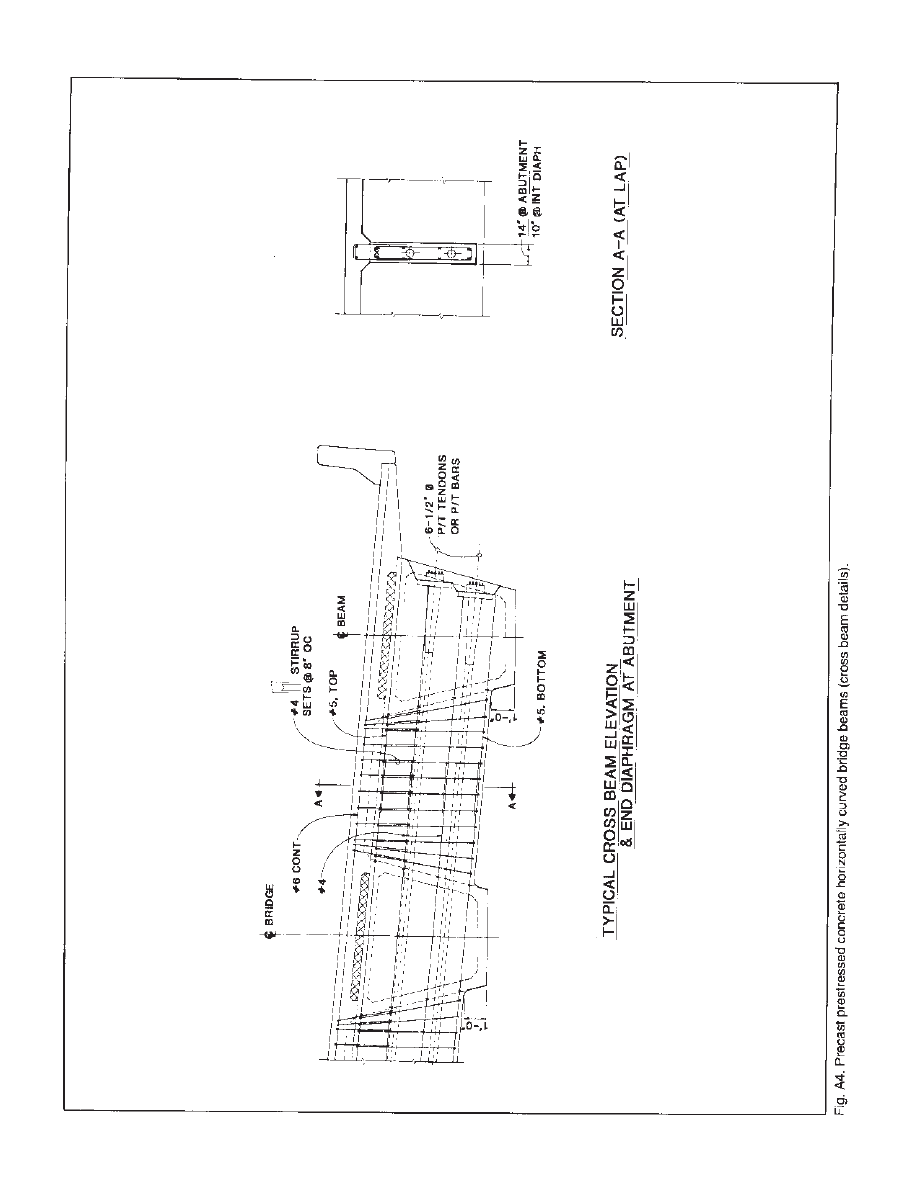
■ Step 3 (Fig. 7): Cross beams are cast
at the midpoint or at the third points along
the span at the nearest diaphragm loca-
tions. The bridge deck is cast. Stage 2 ten-
dons are stressed, placing the deck into
compression. Traffic barriers, overlays,
and expansion joints are placed, complet-
ing the bridge construction.
This horizontally curved prestressed
precast beam concept was selected over
the other concepts (see Table 1) because it
generally:
■ Improved quality
■ Reduced costs
■ Improved aesthetics
Quality was enhanced using a twostage
casting with removable inner forms for
Stage 1. Inner surfaces and thicknesses of
the I beam soffit and webs can be inspect-
ed and positioning of post-tensioning ten-
dons can be carefully established and ver-
ified.
Labor costs to produce full length
beams are reduced by minimizing fabrica-
tion steps. Also, sloping sides delete the
requirement to move back beam side
forms to lift beams from the form.
Material costs are reduced by eliminating
costly inner void forms.
Aesthetics are improved by utilizing
sloping beam sides in lieu of vertical
sides.
Alternative design and fabrication vari-
ations of this concept may be appropriate
for specific project conditions. These
variations are discussed later in this
report.
5
Cost estimates were developed for
bridge superstructures of precast con-
crete, cast-in-place concrete, and struc-
tural steel. The precast alternative
includes the cost of cast-in-place con-
crete cross beams, bridge deck, and traf-
fic barriers. The steel alternative includes
the cost of a concrete bridge deck and
traffic barriers.
A 24-beam project was assumed for
this cost comparison. Projects requir-
ing fewer beams will be more costly
per square foot for the precast alterna-
tive.
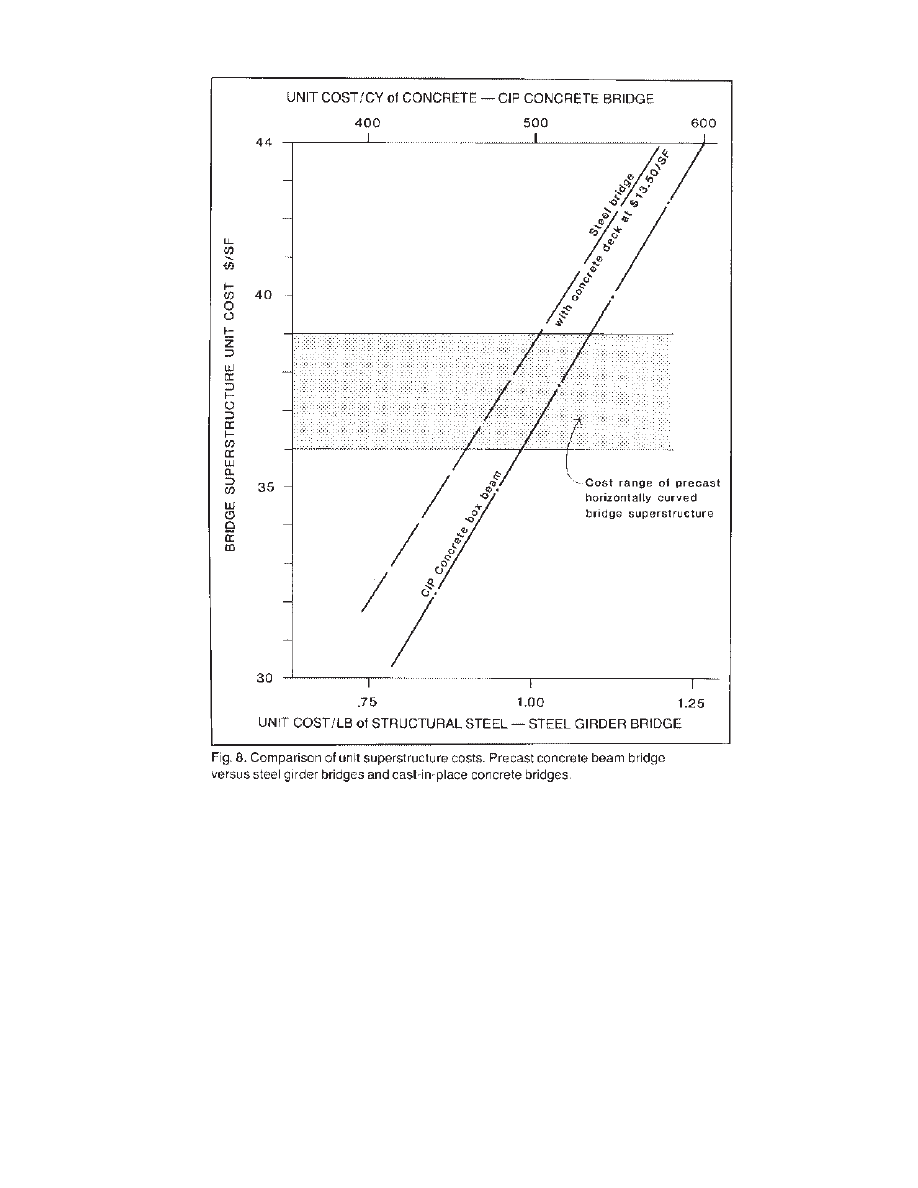
The unit superstructure cost range (per
square foot) for the precast concept ver-
sus the cast-in-place concrete design and
the steel girder bridge design is shown in
Fig. 8. This figure shows that the precast
beam concept is cost competitive with
the steel beam design when the unit steel
price, in place and painted, is more than
$1 per pound ($2000 per ton). Typical
unit prices on curved steel girders range
from $1.00 to $1.50 per pound.
Precast beams are competitive with
cast-in-place concrete box girders when
the in-place unit concrete price exceeds
$530 per cubic yard. Typical
cast-in-place concrete bridges will cost
between $400 and $700 per cubic yard
complete with reinforcing bars and
post-tensioning). Difficult shoring con-
ditions will add to this cost. Also, certain
projects will not allow shoring, therefore
excluding cast-in-place concrete designs.
Horizontally curved bridges made of
precast concrete beams are competitive
with steel girder bridges and cast-
in-place concrete bridges. The amount of
competitive edge will vary with local
project and market conditions.
6
3. COST COMPARISONS
Design of the curved precast beams
addresses flexure, shear, torsion, distor-
tion, and tendon anchoring and deflection
forces. A computer model was developed
for a 120 ft (36.6 m) span 5 ft (1.52 m)
deep girder on a 300 ft (91.5 m) radius to
better understand beam behavior. The
beams, cross beams, and deck were mod-
eled using a grillage of one-dimensional
elements. From this model, analysis tech-
niques were developed for preliminary
design.
Flexure and shear forces can be com-
puted as if the beam were tangent, giving
consideration to the extra length of the
outside beam line that results from hori-
zontal curvature (Fig. 9). Critical stress
conditions are identified for each step of
the construction process.
The beam is post-tensioned at the plant
to carry its own weight (Fig. 10). In this
condition, long beams generally experi-
ence downward deflection. Due to the
beam curvature, the banking, transporta-
tion, and lifting locations are positioned
inward from the ends of the beam over an
appropriate diaphragm to provide over-
turning stability. The beam prestressing is
also adjusted to minimize camber growth
in the stored position. The beam profile in
the form is adjusted for the vertical geom-
etry and for expected elastic and creep
deflections.
The critical stress condition due to
stressing Stage I tendons is tension in the
beam soffit over interior supports (Fig.
11). Temporary tension at this location is
resisted by a positive moment connection
between beams. Upon placing the cross
beams and deck, the critical stress condi-
tion becomes compression in the soffit
over the piers.
7
4. ANALYSIS AND DESIGN
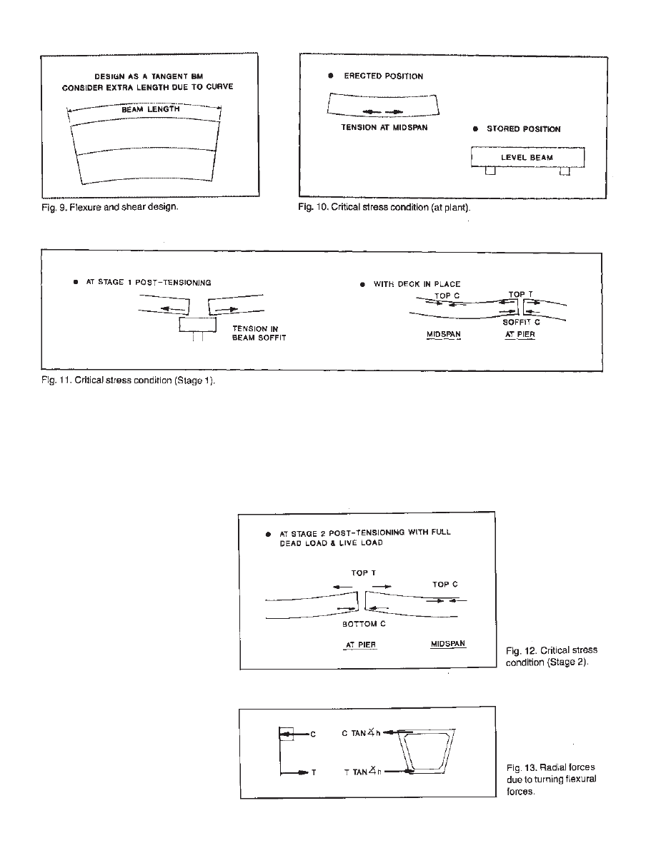
Tension stresses in the top of the beams
over the piers and compressive stresses in
the top of the beams near midspan can
also control the design.
The critical stress conditions at Stage 2,
with the full superimposed dead load and
live load in place, are tension in the bridge
deck and compression in the beam soffit
over interior supports and compression in
the top of the beam near midspan (Fig.
12). The compressive stress at midspan is
theoretically large in the girder top flange
and small in the adjacent cast-in-place
deck. Creep effects, however, will redis-
tribute the large compressive stress from
the beam into the deck. Because the creep
effect is not considered in the preliminary
calculations, the beams designed in this
report use a maximum compressive stress
of 0.5 f ´
c
in the top flange of the precast
beam at midspan. Compression in the
beam soffit near interior supports general-
ly determines the required concrete com-
pressive stress, based on an allowable
compressive stress of 0.4 f ´
c
.
An ultimate strength check is required.
It is recommended that the computation
be done using the capacity of unbonded
post-tensioned tendons. Additional mild
steel can be added to achieve the required
flexural strength. Mild steel reinforce-
ment is used acrossall cold joints along
the beam length. This controls cracking
and improves ductility, which is especial-
ly attractive in seismic risk areas.
Other considerations need to be
accounted for in horizontally curved pre-
cast prestressed concrete bridge beams.
At each horizontal angle point, between
chorded sections, the internal flexural
forces resisting the vertical bending
moment turns through a horizontal angle
8
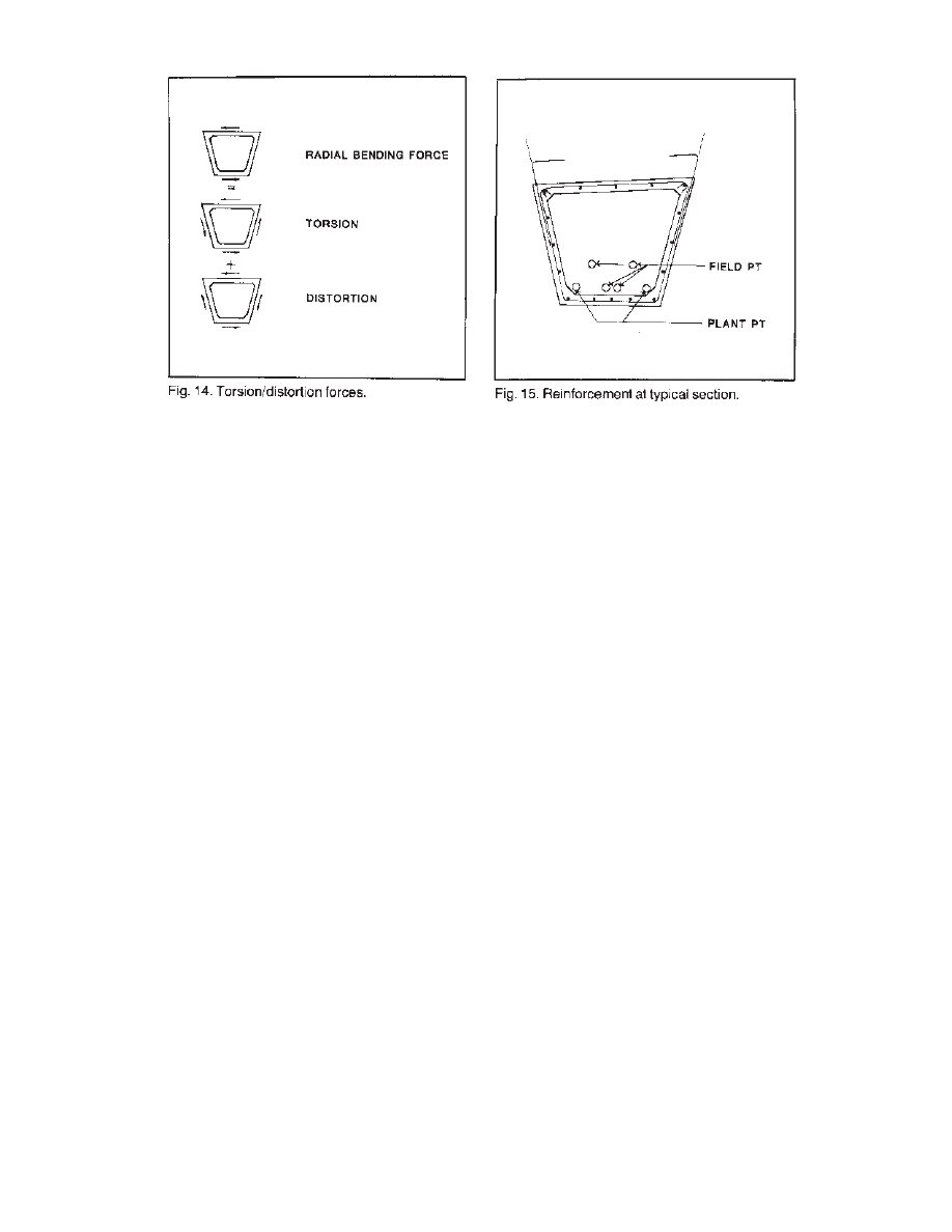
(Fig. 13). Angular deflection of these
forces places horizontal forces in the top
and bottom surfaces of the beams. These
in-plane forces can be broken into tor-
sional and distortion components (Fig.
14). The torsional component is reacted
by the box section and the distortion com-
ponent is resisted by the diaphragm
between chorded segments.
Significant beam torsions are produced
only by the beam self weight acting on a
simple span and by the bridge deck dead
load acting on a continuous beam.
Subsequent twisting of the curved beams
is resisted by thebridge deck and cross
beams.
Shear and torsion design is performed
by distributing the torsional resistance
into individual web shears and adding
web shears reacting vertical forces.
Thickening of webs may be required for
longer beams.
Tendon deflection and anchoring forces
are reacted by the end blocks and the
diaphragms between chorded segments.
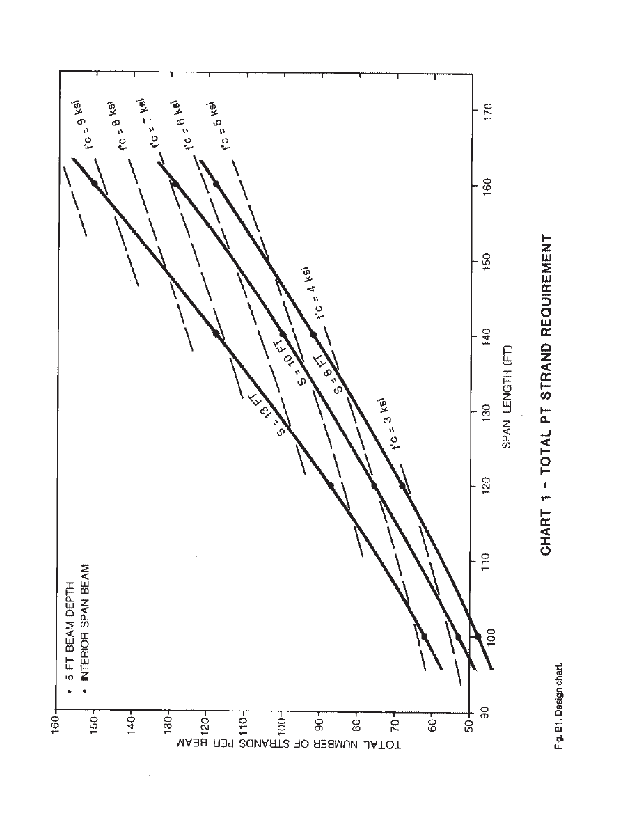
Beam span charts have been developed
that show the required number of
post-tensioning strands per beam for vari-
ous spans and beam spacings. Required
concrete strengths for the design are also
shown. High concrete strengths can be
used to increase girder spacing. Bridge
horizontal curvature has little influence
on post-tensioning requirements. There-
fore, designers can use design charts for
any bridge having the same outside beam
length. Design charts use HS-20 live load.
Beam charts are included in Appendix B
and a design example using the charts is
included in Appendix C.
Typical reinforcement and post-tension-
ing (PT) placement are shown in Fig. 15.
9
5. DESIGN ALTERNATIVES
Situations are presented that require a
concept to offer flexibility to suit the par-
ticular requirements of an owner, bridge
engineer, or precaster. Several variations
in design can be employed to enhance the
usefulness of horizontally curved precast
concrete beams.
Cross Section
A rectangular box section can be used
in lieu of a trapezoidal box section.
Design curves for trapezoidal box cross
sections may be used if rectangular cross
sections have properties similar to trape-
zoidal cross sections shown. Other varia-
tions in the cross section will depend on
the configuration of the bridge and the
intensity of the loads.
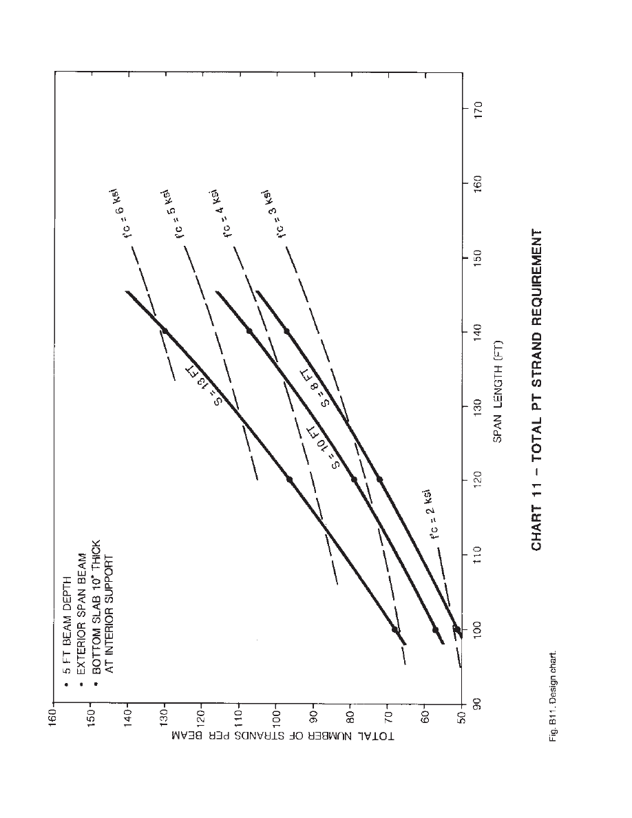
Thickening of Soffit Slab at
Interior Piers
The soffit of the beam near the support
can be thickened to reduce compressive
stresses and therefore the required con-
crete compressive stress. Design Chart 11
can be compared to Design Chart 2
(Appendix B) to determine the amount of
this reduction. Similarly, the thickness of
the top flange of the precast beam could
be increased in the midspan region to
reduce compressive stresses near midspan.
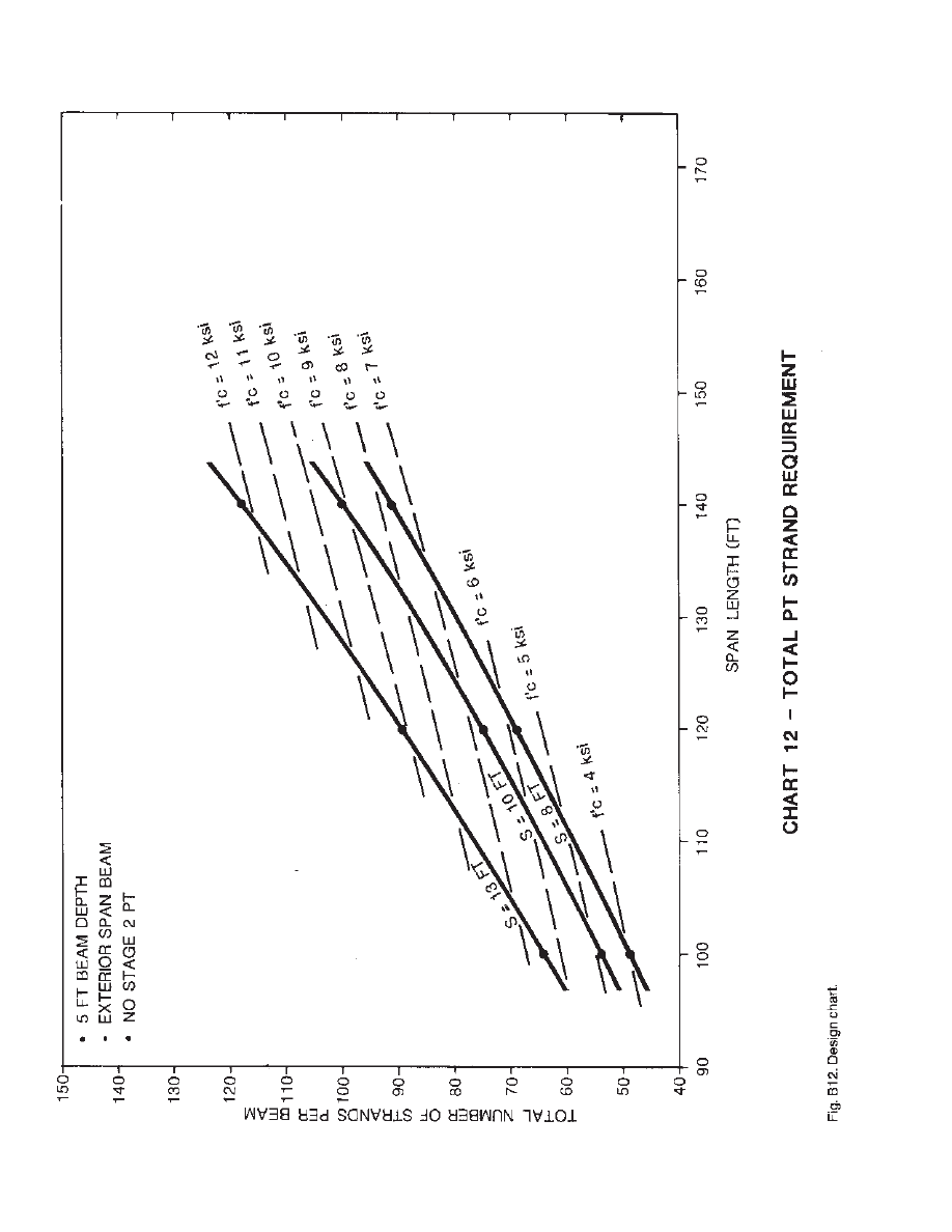
Elimination of the Second Stage of
Field Post-Tensioning
The second stage of field post-tension-
ing can be eliminated. Additional mild
steel is placed in the deck over the piers to
control cracking and provide ultimate
moment strength. This alternative is espe-
cially attractive for areas where the
requirement to totally remove the con-
crete deck for future replacement exists.
Comparison of Design Charts 12 and 2
shows the effect this alternative has on the
number of prestressing strands and on the
required concrete compressive strength.
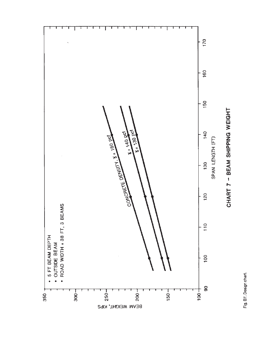
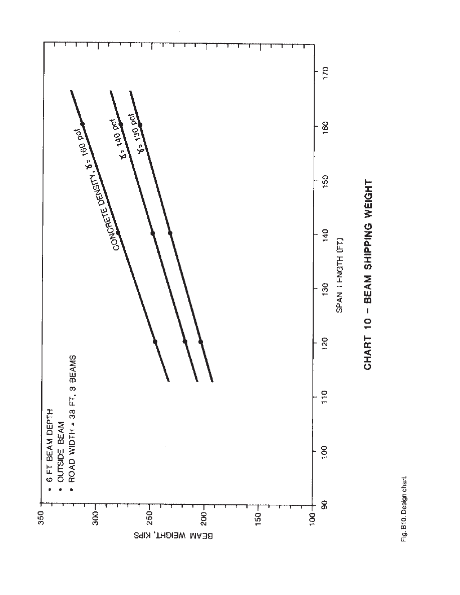
Use of Lightweight Concrete
Lightweight or semi-lightweight con-
crete can be used to reduce beam trans-
portation and erection weight. Reductions
in beam weight can be seen in Charts 7
and 10 (Appendix B).
A concept has been developed for pre-
cast prestressed concrete horizontally
curved bridge beams. The concept uses
trapezoidal box beams made of chorded
segments to approximate curved plan and
profile geometries. Tendons are placedin-
side the void of the beams. High strength
concrete can be used to increase the beam
spacing. Shipping restrictions limit practi-
cal beam span lengths, especially for 6 ft
1.83 m) deep units. Lightweight concrete
or spliced beams can be used to overcome
this limitation. Precast prestressed bridge
beams can be a viable option for horizon-
tally curved bridges, giving bridge owners
and engineers an alternative to steel gird-
ers and to, cast-in-place concrete struc-
tures.
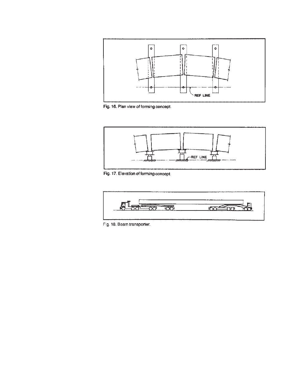
Form Concept
A forming concept for fabricating full
span length chorded beams was devel-
oped. The segments move and rotate
along guide beams to provide the hori-
zontal curvature (Fig. 16). The elevations
of the guide beams can be adjusted using
jacks to provide the vertical profile (Fig.
17). The segments are not twisted or
warped. These variations can be accom-
modated in the cast-in-place deck.
Beam Weight
The weight of precast concrete beams is
a major concern. A maximum shipping
weight of 314,000 lb (142,430 kg) (haul-
ing equipment plus beam) was selected to
identify limiting span lengths. This
weight is equal to the P13 permit design
load used on California’s highway sys-
tem.
Shipping these large loads requires spe-
cial transporters (Fig. 18). There are units
that have been used to transport girders of
similar size. For instance, 13-axle trans-
porters are available on the west coast.
The 318,000 lb (144,245 kg) shipping
weight places an axle load of 24 kips (107
kN) on axles 41/2 ft (1.37 in) apart.
This is similar to the axle loads for the
AASHTO military loading. The maxi-
mum shipping weight translates into an
effective beam transportation weight of
254,000 lb (115,214 kg). This beam
weight limits the shipping length of the 6
ft (1.83 in) deep section to 130 ft (39.6 in)
and the 5 ft (1.52 in) deep section tion to
150 ft (45.7 m).
Alternative Production Methods
Alternative production techniques also
were investigated.
Individual 20 ft (6.10 m) long chorded
beam segments could be fabricated and
then assembled into span length beams at
the plant. This option reduces beam form-
ing costs but increases the number of pro-
duction steps. This alternative may be
advantageous on projects requiring a
small number of beams.
Optional void materials could be used.
The concept was designed around a
two-pour beam casting using steel inner
forms with an expendable wood deck sof-
fit form. Polystyrene or wood forms could
be used. However, production problems
with these expendable voids need to be
carefully considered.
Beams can also be spliced in the field to
reduce shipping weight and to produce
longer spans.
10
6. FABRICATION TECHNIQUES
7. CONCLUSION

11
• • •
APPENDIX
•
APPENDIX A — CONCEPTUAL DRAWINGS AND DETAILS
•
APPENDIX B — DESIGN CHARTS
•
APPENDIX C — DESIGN EXAMPLE
• • •
APPENDIX A — CONCEPTUAL DRAWINGS
AND DETAILS
1. Barnoff, Robert, M.; Nagle, Gordon;
Suarez, Mario, G.; Geschwindner,
Louis, F., Jr.; Merz, H. William, Jr.; and
West, Harry, H.; “Design, Fabrication,
and Erection of a Curved Prestressed
Concrete Bridge With Continuous
Girders,” Transportation Research Record
950,1985, pp. 136-140.
REFERENCE
12
13
14
15
16
17
18

APPENDIX B - DESIGN CHARTS
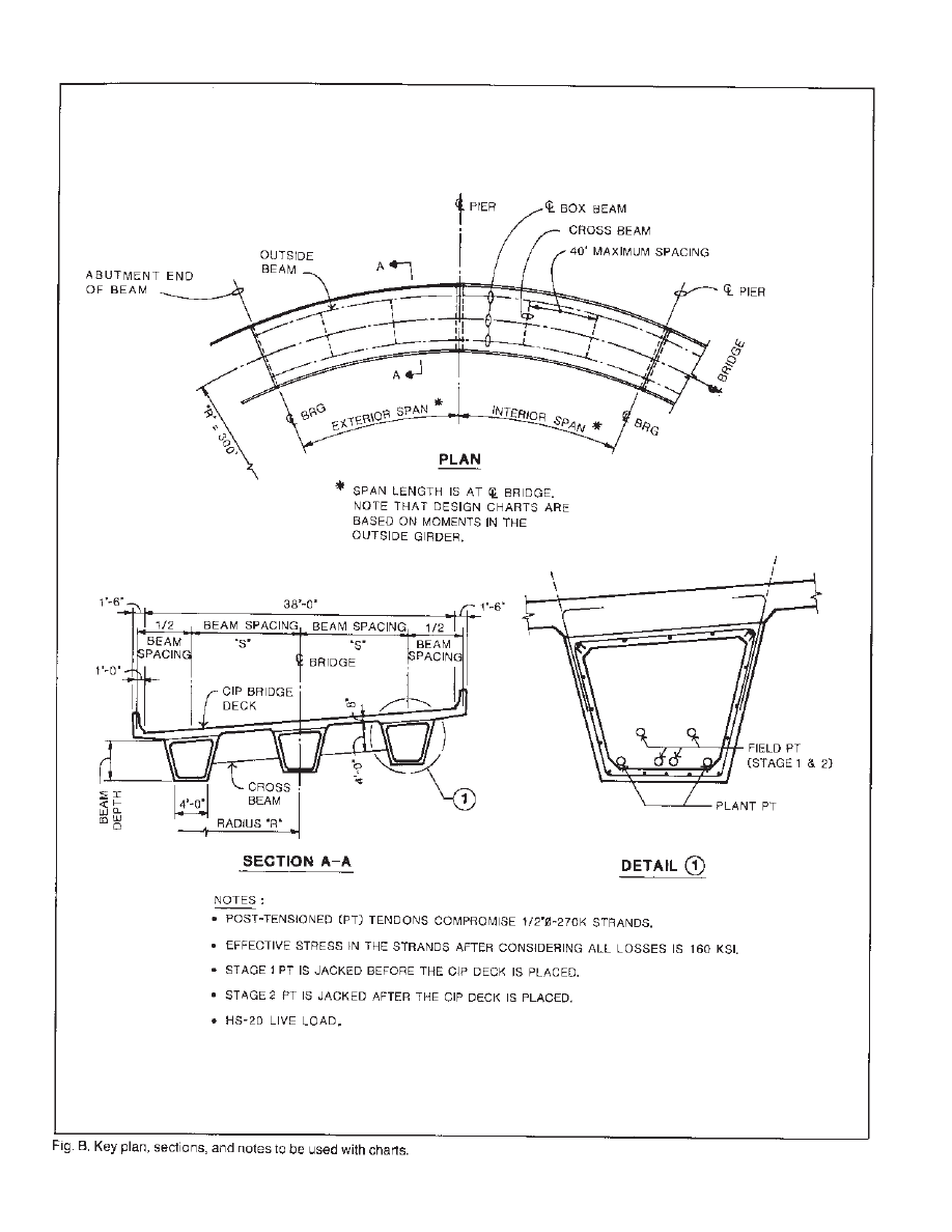
GENERAL
Fig. B. Key plan, sections, and notes to be used with charts.
5 FT (1.52 M) DEEP BOX BEAM
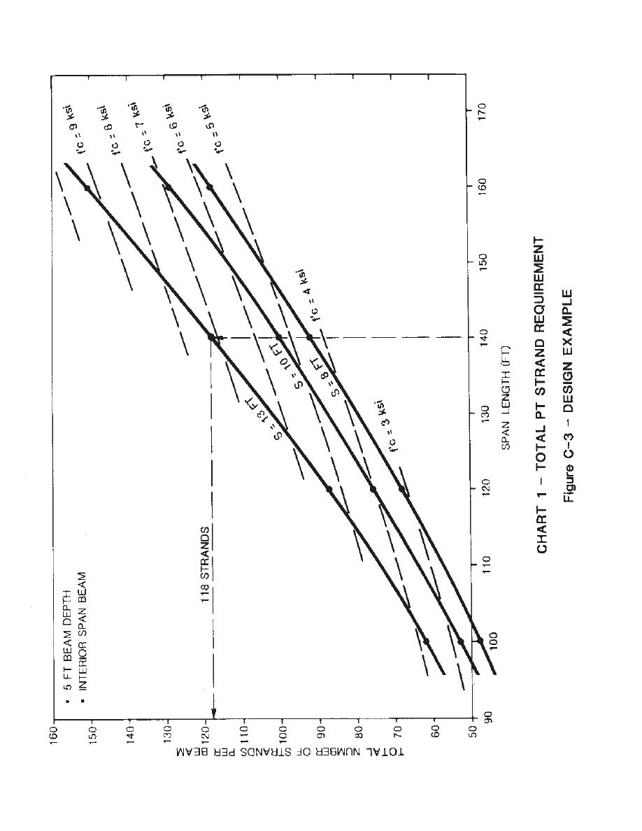
Chart 1. Total post-tensioned strand requirement (interior span beam).
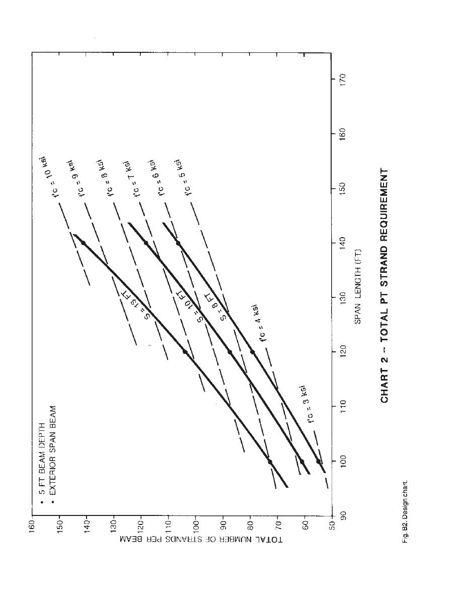
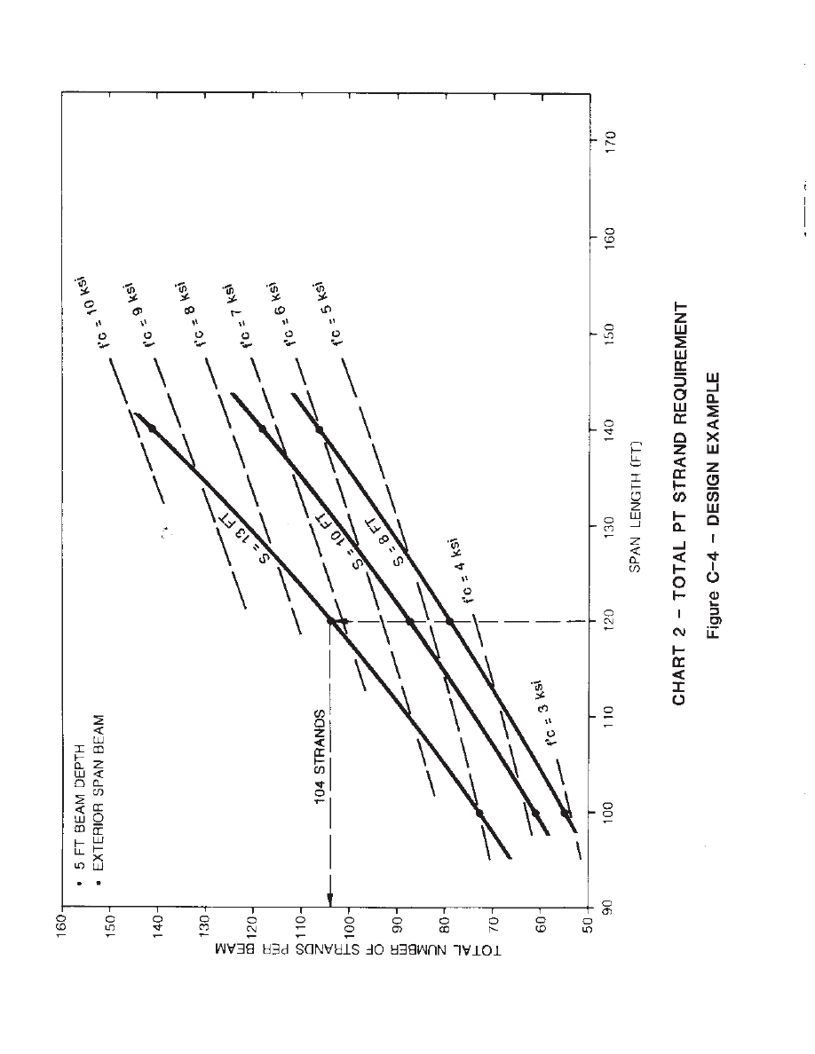
Chart 2. Total post-tensioned strand requirement (exterior span beam).
Chart 3. Post-tensioned strand requirement (interior span beam, beam spacing = 13 ft).
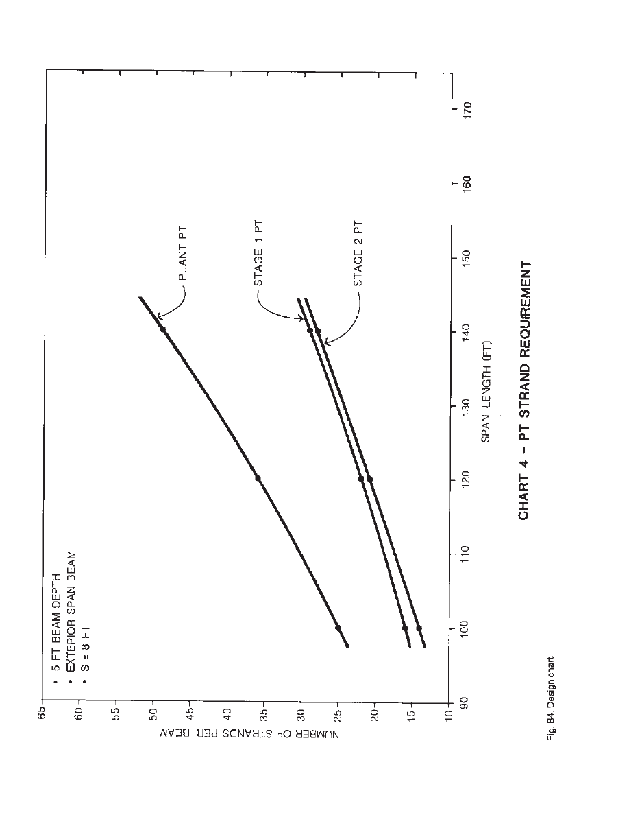
Chart 4. Post-tensioned strand requirement (exterior span beam, beam spacing = 8 ft).
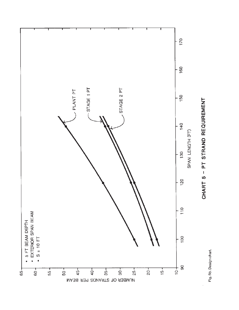
Chart 5. Post-tensioned strand requirement (exterior span beam, beam spacing = 10 ft).
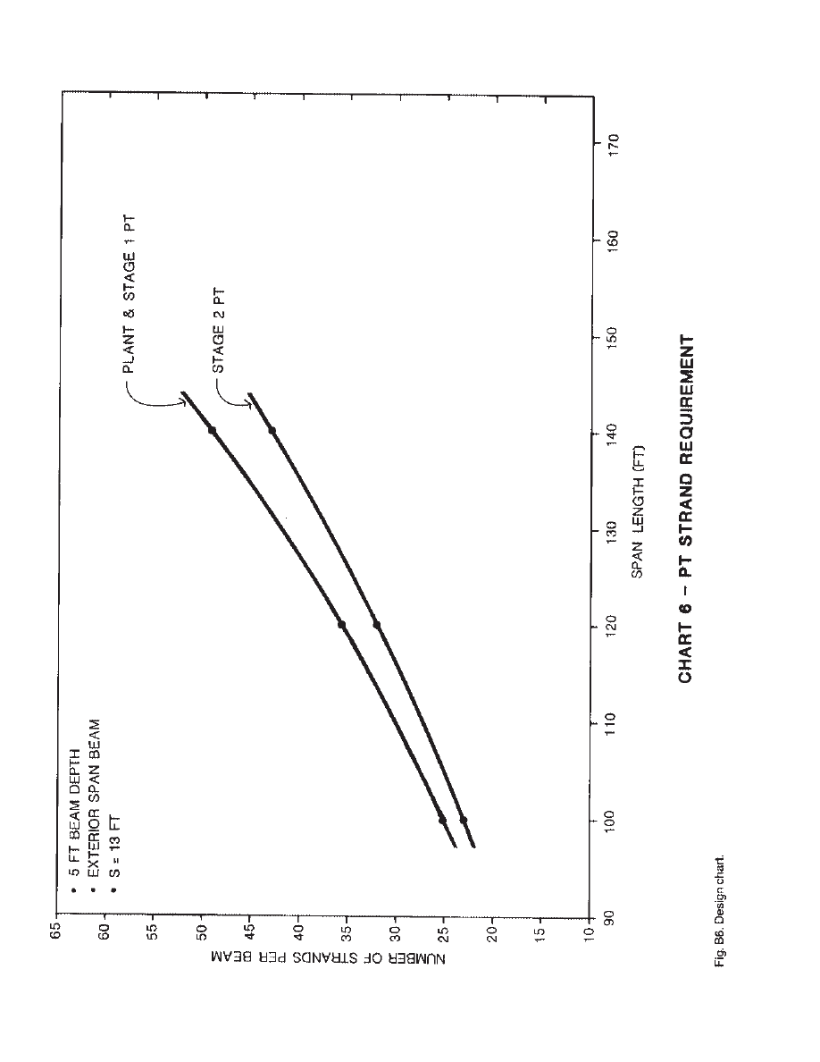
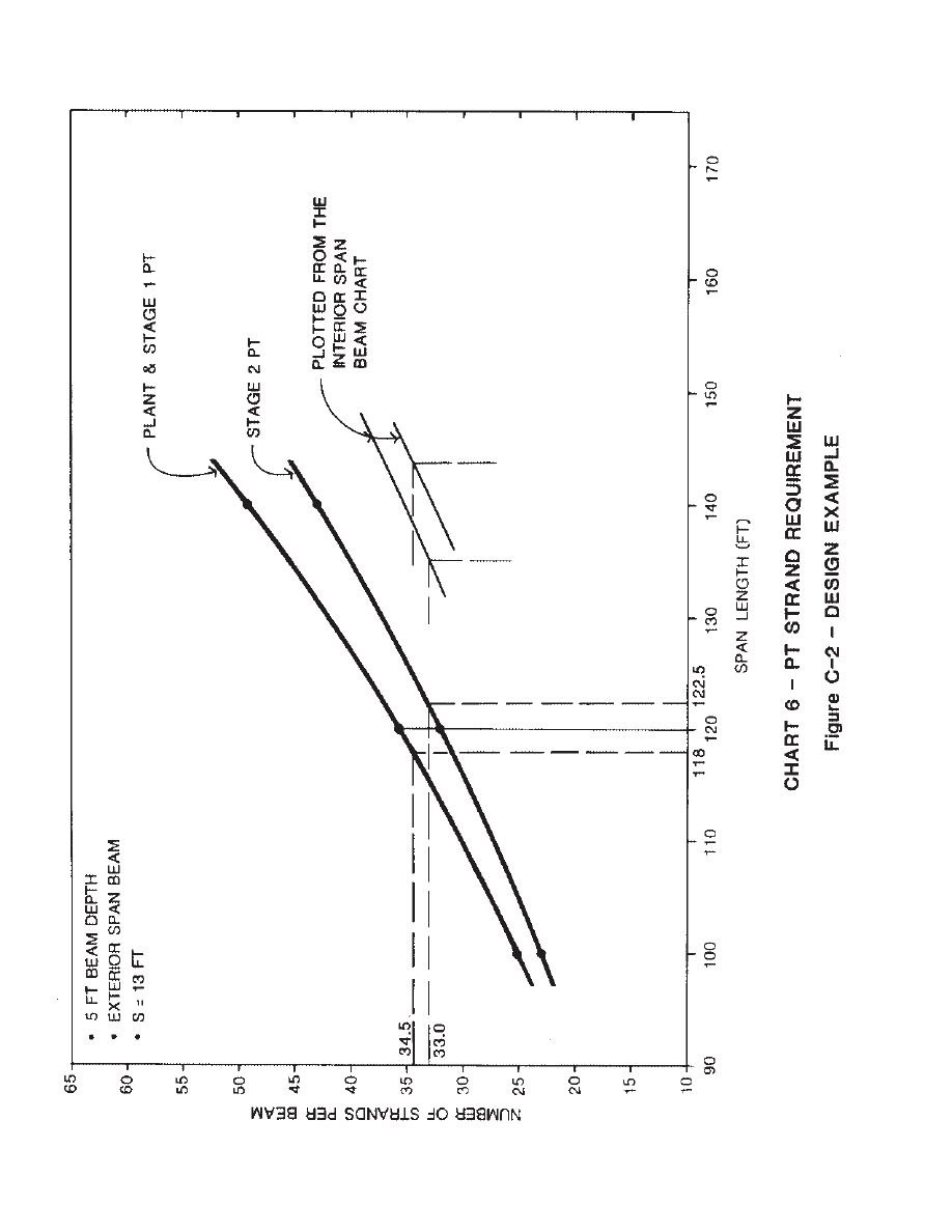
Chart 6. Post- tensioned strand requirement (exterior span beam, beam spacing = 13 ft).
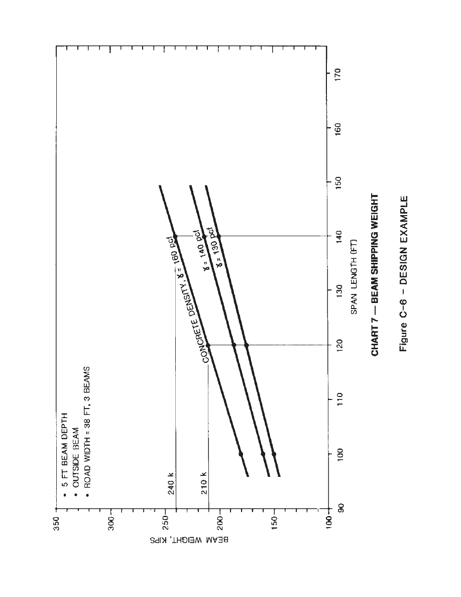
Chart 7. Beam shipping weight.
6 FT (1 .83 M) DEEP BOX BEAM
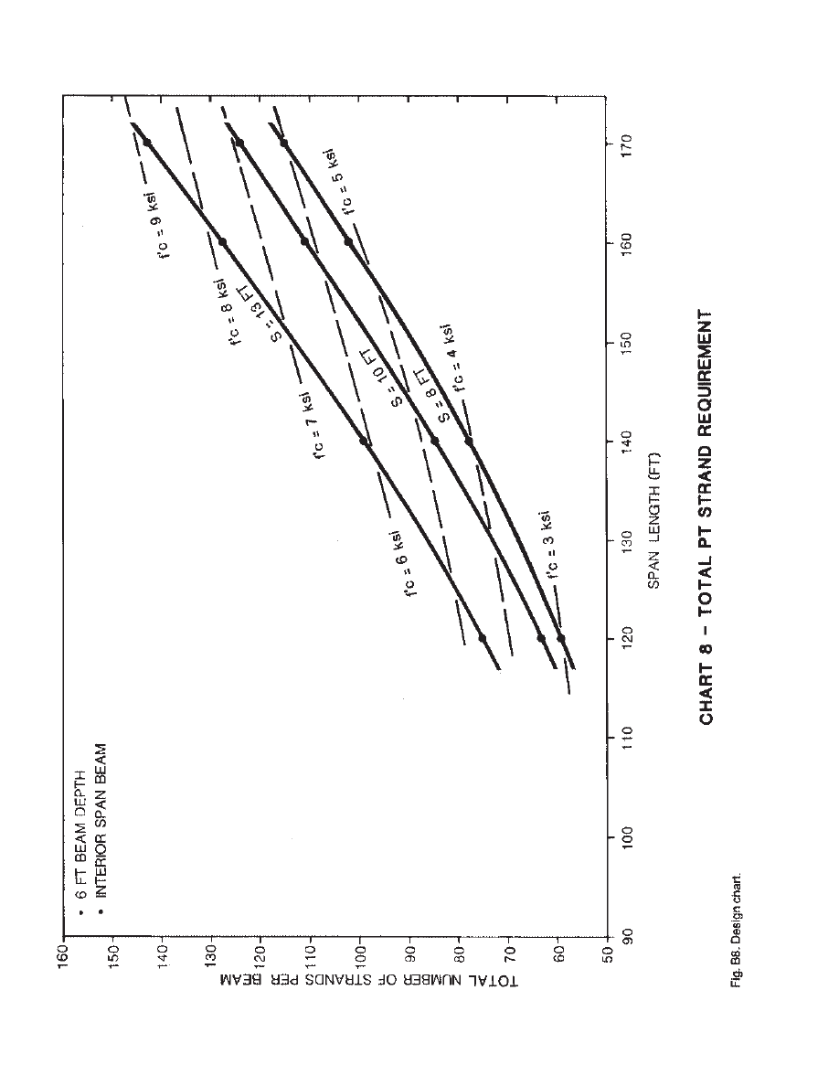
Chart 8. Total post-tensioned strand requirement (interior span beam).
Chart 9. Total post-tensioned strand requirement (exterior span beam).
Chart 10. Beam shipping weight.
DESIGN ALTERNATIVES, 5 FT (1.52 M) DEEP BOX BEAM
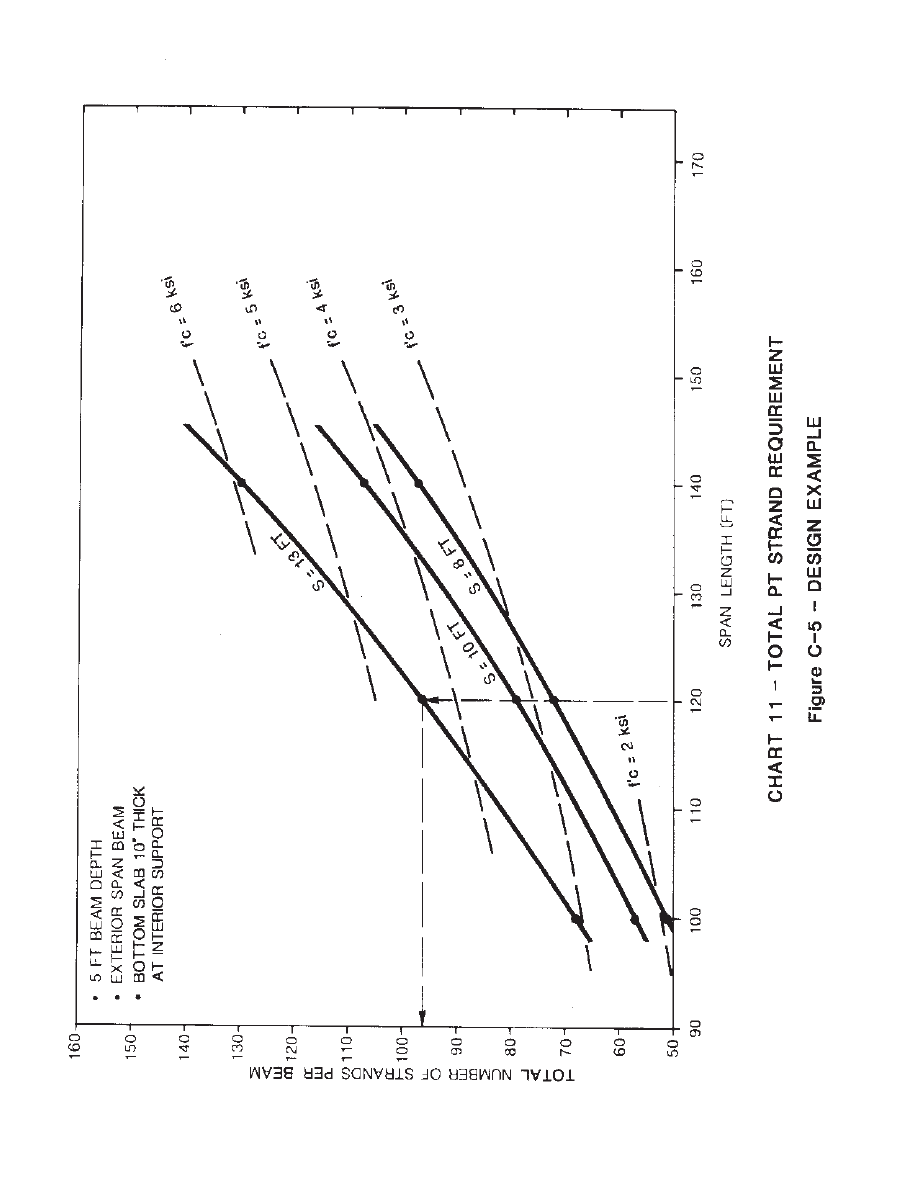
Chart 11. Total post-tensioned strand requirement (exterior span beam, thickened
bottom slab).
Chart 12. Total post-tensioned strand requirement (exterior span beam, no Stage 2
post-tensioning).
19
20
21
22
23

24
25
26
27
28

29
30
31
32
Perform Preliminary
Flexural Design
Bridge ge length= 380 ft 16 (116 m)
Roadway width W = 38 ft (I 11.6m)
Roadway radius R = 300 ft (91.5 m)
Use beam depth = 5 ft (1.52 m)
Number of spans: 380/3 = 127 ft (38.7 m)
avg
Try three spans.
380/4 = 95 ft (29.0 m) avg
The number of beams, Ng (or beam
spacing, S), can be determined from the
design charts.
Try three beams [spacing = 13 ft (3.92
m)].
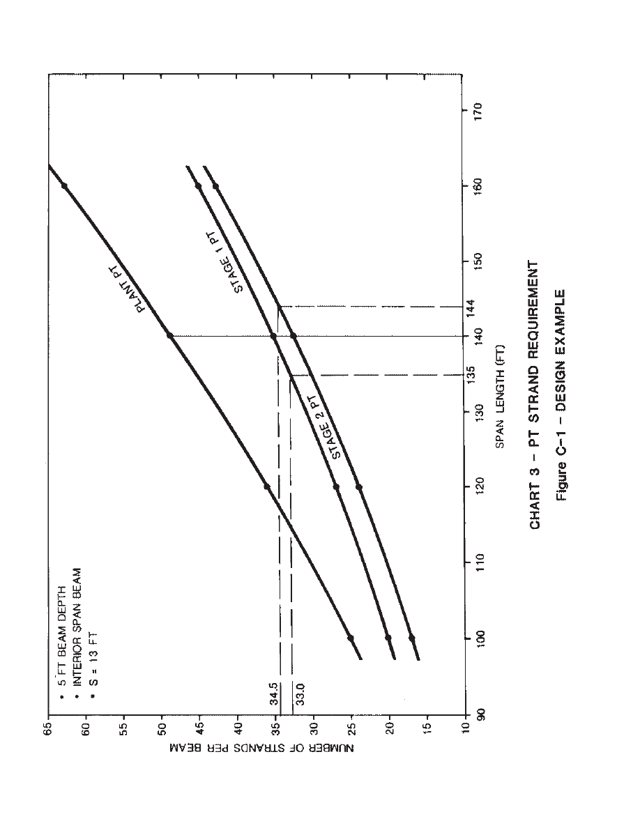
To optimize the post-tensioning design,
enter 5 ft (1.52 m) beam depth charts
(exterior and interior span beams) with
plot of strand required versus span for
three beams (see Figs. C1 and C2).
Find the combination of exterior and
interior span lengths that add up to the
total bridge length and that has the same
number of strands required for each stage
of field post-tensioning.
The plant post-tensioning supports the
beam as a simple span and is not continu-
ous; therefore, the required number of
strands will be greater for the longer inte-
rior spans. It does not control the ratio of
spans.
Stage 1 field post-tensioning is to sup-
port the cast-in-place bridge deck dead
load and is continuous across interior sup-
ports. The number of strands is the same
in the tendon. There will be some differ-
ence in the final stresses of the strand
along the span from the end anchor to the
center of the bridge (assuming stressing is
done from both ends of the bridge) due to
losses.
From the charts, find the spans that add
up to the total length for the same number
of strands in Stage 1:
Using the same charts, similar calcula-
tions are done for determining the spans
for Stage 2 post-tensioning:
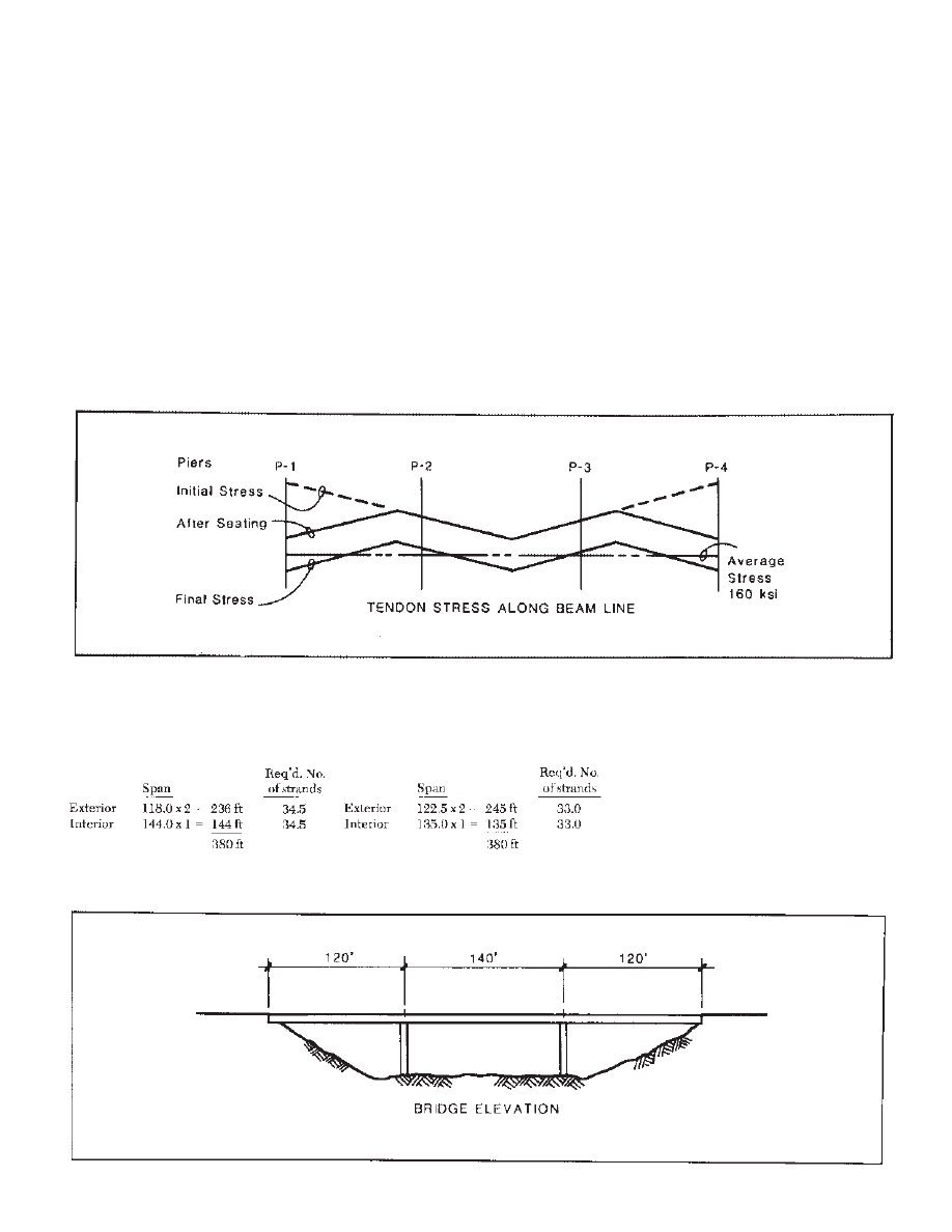
The vertical lines plotted on the charts
will bracket an efficient design solution.
Any choice in between will require a few
more strands. By inspection, use:
Span= 120 + 140 + 120
= 380 ft (1 16m)
The sketch below shows the final span
arrangement of the bridge structure.
33
APPENDIX C - DESIGN EXAMPLE

Strand Required (Figs. C3 and C4):
Adjusted
By chart
strand
strand
require-
required
ment
Exterior span:
5 ft beam depth,
three beams (S = 13 ft)
Plant post-tension
36
36
Stage 1 post-tension
36
36
Stage 2 post-tension
32
36*
104
108
Interior span: 5 ft beam depth,
three beams (S = 13 ft)
Plant post-tension
49
49
Stage I post-tension
33
36*
Stage 2 post-tension
36
36
118
121
*Increase
Required 28-Day Compressive
Strength (see Figs. C3 and C4)
Exterior span: f ´
c
= 7300 psi (50.4 MPa)
Interior span: f ´
c
= 7200 psi (49.7 MPa)
Say: f ´
c
= 7500 psi (51.7 MPa)
This requirement can be significantly
reduced by thickening the bottom slab the
interior continuous supports, because the
compressive strength requirements shown
on the charts are generally governed by
compression in the bottom slab at the
interior support (see Fig. C5.
There are significant compressive stress-
es at the top of the bare beam at midspan
prior to casting the deck; however, service
level stresses in the deck are relatively low,
allowing creep effects to reduce the com-
pressive stress in the beam.
f ´
c
might be reduced to 6000 psi (41.4
MPa).
Exterior span = 4500 psi (31.0 MPa)
Beam Shipping Weight (see Fig. C6)
Exterior span beam shipping weight =
210 kips (934 kN)
Interior span beam shipping weight =
240 kips (1067 kN)
34
35
36
37
38
39
40

Wyszukiwarka
Podobne podstrony:
HORIZONTALLY CURVED STEEL BOX GIRDER BRIDGE AASHTO LRFD Design example
Prestressed Concrete 4
Behaviour of precast reinforced concrete pile caps
Behaviour of precast concrete floor slabs exposed to standar
(01899NB) Sylamore Creek Bridge (concrete arch not built)
04 Bridge monitoring by horizontal displacement at girder ends
(00588NB) North Fork Bridge (concrete arch not built)
Eurocode 2 Part 2 2004 UK NA Design of concrete structures Concrete bridges Design and detailin
H BRIDGE PCB
przeglądarka plików Adobe Bridge
Monitor Bridge CAE 3645G
Concrete Walkways
H BRIDGE nom RESISTORS id 19832 Nieznany
Monitor Bridge CAE 5645
Concrete Mixing
Dark Horizons Universe Crisis on Sol Observatory
więcej podobnych podstron