
INSTRUCTION
MANUAL
G-5500
YAESU MUSEN CO., LTD.
1-20-2 Shimomaruko, Ota-Ku, Tokyo 146-8649, Japan
YAESU U.S.A.
17210 Edwards Rd., Cerritos, CA 90703, U.S.A.
YAESU INTERNATIONAL DIVISION, (Caribbean, Mexico, Central & So. America)
7270 NW 12th St., Suite 320, Miami, FL 33126, U.S.A.
YAESU EUROPE B.V.
Snipweg 3, 1118DN Schiphol, The Netherlands
YAESU UK LTD.
Unit 2, Maple Grove Business Centre,
Lawrence Rd., Hounslow, Middlesex, TW4 6DR, U.K.
YAESU GERMANY GmbH
Am Kronberger Hang 2, D-65824 Schwalbach, Germany
YAESU HK LTD.
11th Floor Tsim Sha Tsui Centre, 66 Mody Rd.,
Tsim Sha Tsui East, Kowloon, Hong Kong

P
AGE
1
G-5500 Antenna Azimuth-Elevation Rotators & Contoroller Instruction Manual
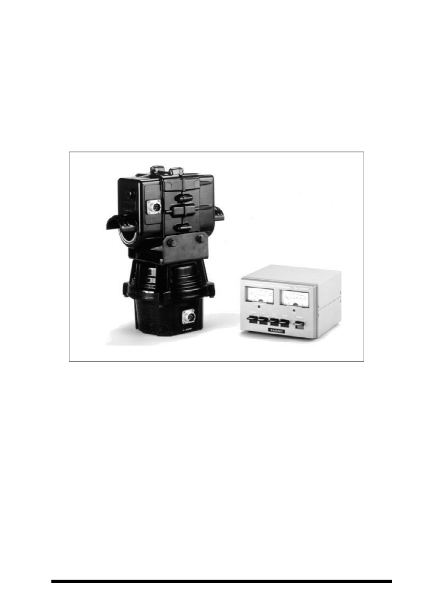
The Yaesu G-5500 provide 450° azimuth and 180° elevation control of medium- and large-size
unidirectional satellite antenna arrays under remote control from the station operating position.
The two factory-lubricated rotator units are housed in weatherproof melamine resin coated die-cast
aluminum, to provide maintenance-free operation under all climatic conditions. The rotators may
be mounted together on a mast, or independently with the azimuth rotator inside a tower and the
elevation rotator on the must.
The controller unit is a handsomely-styled desktop unit with dual meters and direction controls for
azimuth, in compass direction and degrees; and elevation, from 0° to 180°. An External Control
jack is provided on the rear of the controller for interfacing via D-to-A converters to an external
microcomputer or other display/controller.
Please read this manual carefully before installing the rotators.
YAESU G - 5500
ANTENNA AZIMUTH-ELEVATION
ROTATORS & CONTROLLER

P
AGE
2
G-5500 Antenna Azimuth-Elevation Rotators & Contoroller Instruction Manual
SPECIFICATIONS
Voltage requirement:
110-120 or 200-240 VAC
Motor voltage:
24 VAC
Rotation time (approx., @60Hz): Elevation (180°): 67 sec.
Azimuth (360°): 58 sec.
Maximum continuous operation: 5 minutes
Rotation torque:
Elevation: 14 kg-m (101 ft-lbs)
Azimuth: 6 kg-m (44 ft-lbs)
Braking torque:
Elevation: 40 kg-m (289 ft-lbs)
Azimuth: 40 kg-m (289 ft-lbs)
Vertical load:
200 kg (440 lbs)
Pointing accuracy:
±4 percent
Wind surface area:
1 m
2
Control cables:
2 x 6 conductors - #20 AWG or larger
Mast diameter:
38-63 mm (1-1/2 to 2-1/2 inches)
Boom diameter:
32-43mm (1-1/4 to 1-5/8 inches)
Weight:
Rotators: 9 kg (20 lbs)
Controller: 3 kg (6.6 lbs)
UNPACKING & INSPECTION
When unpacking the rotator confirm the pres-
ence of the following items:
Elevation Rotator Unit ................................. 1
Azimuth Rotator Unit .................................. 1
Controller Unit ............................................. 1
Mast Clamp (pair) ........................................ 2
Pipe clamp ................................................... 2
U Bracket ..................................................... 1
M8 x 16 Hex. Bolt ....................................... 4
M8 x 25 Hex. Bolt ....................................... 8
M8 x 70 Hex. Bolt ....................................... 4
M8 x 95 Hex. Socket Bolt ........................... 1
U-Bolt .......................................................... 2
6mm Spring Washer .................................... 4
6mm Flat Washer ......................................... 4
8mm Spring Washer .................................. 18
8mm Flat Washer ....................................... 12
M8 Square Nut............................................. 1
M8 Hex. Nut ................................................ 4
M6 Hex. Nut ................................................ 4
8-pin DIN Plug ............................................ 1
7-pin Metal Connector ................................. 2
Water Resist Cap ......................................... 2
Spare Fuse (117V:2A, 220V:1A) ................. 1
Instruction Manual ....................................... 1
If any of these items are missing or appear to
be damaged, save the carton and packing ma-
terial and notify the shipping company (or
dealer, if purchased directly at his shop).
Before proceeding with installation, confirm
that the AC voltage label on the rear of the
Controller matches your local line voltage: ei-
ther “117V” for 110 to 120 VAC, or “220” for
220 to 240 VAC. If the labeled voltage range
does not match, return the controller to the
dealer from whom you purchased it (different
power transformers are installed for the differ-
ent voltage ranges).
Note that cable is not included with the rotator,
as the length must be determined case-by-case.
Contact your Yaesu dealer to obtain the length
of cable your installation requires. For runs of
over 100 feet, use #18 AWG instead of #20
AWG.
P
AGE
3
G-5500 Antenna Azimuth-Elevation Rotators & Contoroller Instruction Manual
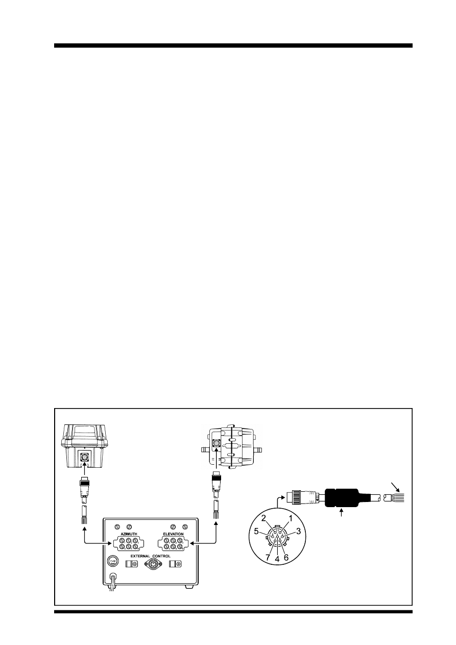
CONTROL CABLE PREPARATION & CONNECTION
Before installing the antenna and rotators, make all connections and test rotator operation thor-
oughly on the ground as described below.
Your control cables should have six conductors each of at least #20 AWG gauge (if less than 100
feet long).
1.
Assemble the cable according to the fol-
lowing diagrams.
2.
Connect each wire to the terminals on the
rear panel of the controller, making sure to
match the numbers on the pins, and insert
the connector to the Jack on the rotator.
3.
On the controller, make sure that the
POWER switch is in the “OFF” position,
and connect the line cord to the AC power
outlet.
4.
Turn on the POWER switch. The meter
lamps should light and the ELEVATION
meter indicate to the center of the scale
(90°).
5.
Press the UP switch. The elevation rota-
tor should turn as the meter indication
moves to the right. Release the UP switch
and confirm that the rotator slowly stops.
6.
Repeat step 5, pressing the DOWN switch
instead of the UP switch. The elevation
rotator should turn in the opposite direc-
tion as the meter indication moves to the
left.
7.
If operation does not occur as described
above, check for a wiring error in the el-
evation cable connections.
8.
Press the LEFT switch. The azimuth ro-
tator should turn counterclockwise as the
meter indication moves to the left. Release
the LEFT switch and confirm that the ro-
tator slowly stops.
9.
Repeat step 8, pressing the RIGHT switch
instead of the LEFT switch. The azimuth
rotator should turn clockwise as the meter
indication moves to the right.
10. If operation does not occur as described in
steps 8 and 9, check for a wiring error in
the azimuth cable connections.
11. When everything checks out in the above
steps, slide the water resist cap over the
connectors on the rotator. Remove the
cable clamps from the controller, clip them
over the cables, and screw them back onto
the controller. Then replace the two con-
troller terminal covers.
Make sure to insert the
Water Resist Cap first.
Tin the wire with solder.
Terminal 7 is not used.
P
AGE
4
G-5500 Antenna Azimuth-Elevation Rotators & Contoroller Instruction Manual
PRE-INSTALLATION ADJUSTMENT
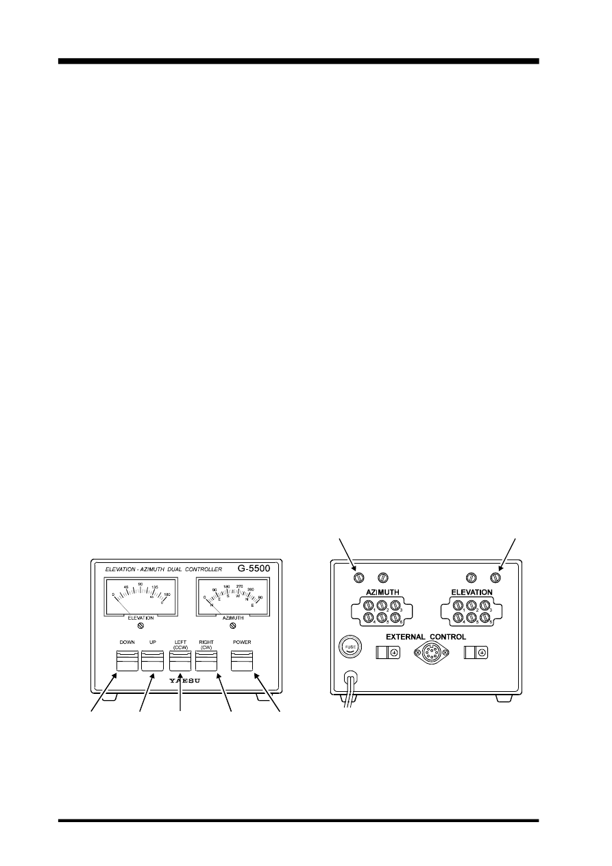
Switch the controller off and adjust the 0. ADJ screws beneath each meter face, if necessary, so that
each meter points to the left edge of the scale. Then turn the controller back on for the following
steps.
Azimuth Indicator
Press and hold the LEFT switch and allow the
azimuth rotator to turn until it reaches its end
stop. Note the precise position of the rotator
(mark the housing, if necessary), and then press
and hold the RIGHT switch to bring the rota-
tor around one full turn to exactly the same po-
sition. The meter should now point precisely
to 360° of the scale. If not, adjust the FULL
SCALE ADJ potentiometer at the upper cor-
ner of the rear panel above the AZIMUTH ter-
minals.
Press the RIGHT switch again to continue
clockwise rotation until the rotator reaches its
end-stop. The indicator should now point to
right edge (90°) of the scale.
Elevation Indicator
Press the UP switch to align the 180° markers
on the rotator. The meter should now point
precisely to 180° at the right end of the scale.
If not, adjust the FULL SCALE ADJ potenti-
ometer at the upper corner of the rear panel
above the ELEVATION terminals.
Notes on Controller Operation:
m The rotator motors are rated for five-min-
utes intermittent duty. However, they be
brought to rest for at least 15 minutes after-
wards.
m If both UP and DOWN switches or RIGHT
and LEFT switches are pressed at the same
time, the corresponding rotator turns up or
right (clockwise).
m Release the switch when the meter indicates
in the end zones (the rotator stops).
m Remember to turn the controller off when
the rotators are not in use.
DOWN
Switch
UP
Switch
LEFT
Switch
RIGHT
Switch
POWER
Switch
Azimuth
Full Scale
Elevation
Full Scale
P
AGE
5
G-5500 Antenna Azimuth-Elevation Rotators & Contoroller Instruction Manual
7
3
8
6
1
4
2
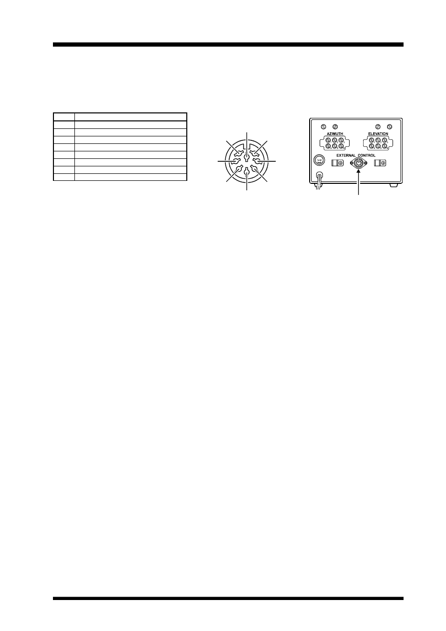
External Control
5
EXTERNAL CONTROL
IF the optional GS-232 Computer Control Interfaces Unit is installed, the RS-232C cable from the
computer routes through this grommet, and is affixed in place by the nylon cable clamp.
P i n
6
1
4
2
5
3
7
8
Function
Provides 2 to 4.5VDC corresponding to 0 to 450°
Provides 2 to 4.5VDC corresponding to 0 to 180°
Connect to Pin 8 to rotate left (counterclockwise)
Connect to Pin 8 to rotate right (clockwise)
Connect to Pin 8 to rotate UP
Connect to Pin 8 to rotate DOWN
Provides DC13V to 6V at up to 200mA
Common ground
P
AGE
6
G-5500 Antenna Azimuth-Elevation Rotators & Contoroller Instruction Manual
ROTATOR INSTALLATION
The maximum safe load of the G-5500 depends
on the physical size of the antenna, method and
quality of mechanical installation, and maxi-
mum wind velocity at the installation site.
Notice that the preferred mounting method re-
quires that each antenna be attached to the
boom at its center of gravity, with the boom
then attached to the elevation rotator at its cen-
ter of gravity. This minimizes stress on the
rotator and supporting structure, especially
during strong winds.
The azimuth rotator may be mounted at the top
of the mast together with the elevation rotator,
or separately inside of a supporting tower. The
latter method is generally stronger, and prefer-
able in high wind locations or for large anten-
nas, but requires some additional hardware not
supplied with the G-5500 kits.
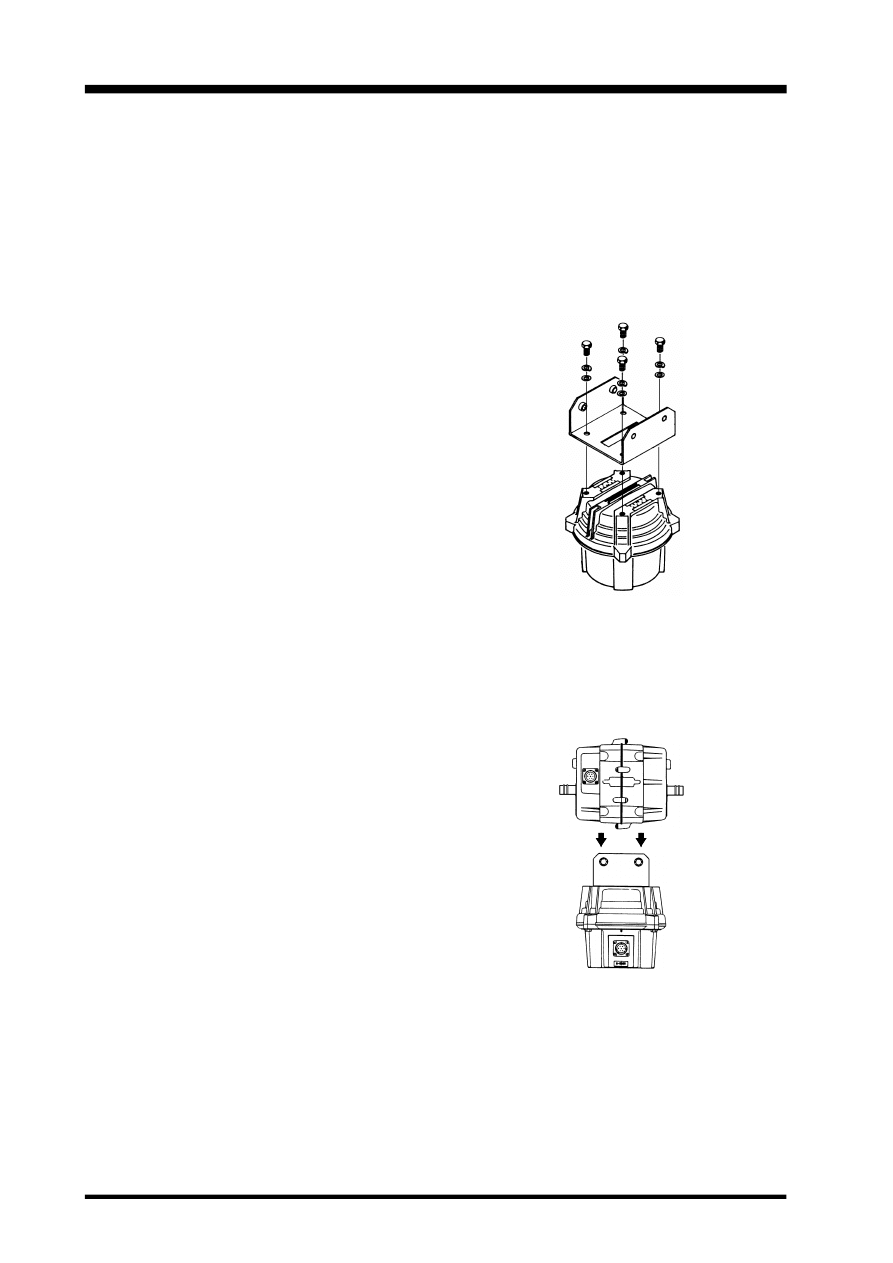
Mounting the Rotators Together
NOTE: If the elevation rotator is to be mounted
on the mast alone, skip this section and see
“Mounting the Rotators Separately”.
1.
Bolt the U-bracket to the top of the azi-
muth rotator using four M8x16 bolts,
spring washers and flat washers.
2.
Insert the elevation rotator into the U-
bracket, then fasten the elevation rotator
using four M8x25 bolts, spring washers
and flat washers.
P
AGE
7
G-5500 Antenna Azimuth-Elevation Rotators & Contoroller Instruction Manual
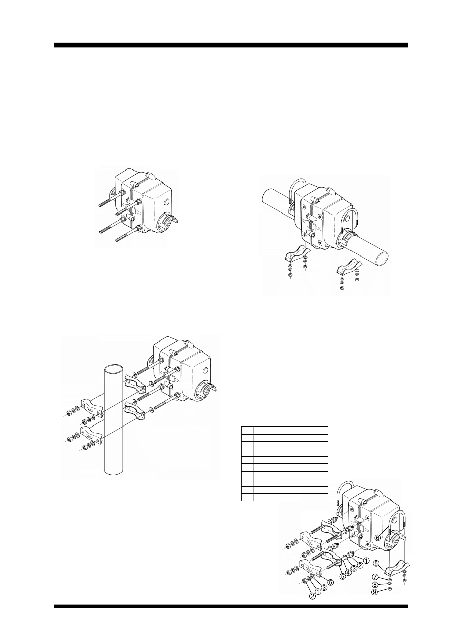
No
Qty
DESCRIPTION
1
8
8
Ø
Spring Washer
2
8
8
Ø
Nut
3
8
8
Ø
Washer
4
4
8
Ø
Stud Bolt
5
6
Boom/Mast Clamp
6
2
U Bolt
7
4
6
Ø
Washer
8
4
6
Ø
Spring Washer
9
4
6
Ø
Nut
Mounting the Rotators Separately
Only do this if the elevation rotator is to be
mounted alone on the mast. You will need four
long stud bolts and four additional pipe clamps
(available from your dealer).
1.
Slip an 8 mm spring washer over the short-
thread end of each stud bolt (x4), and screw
the stud bolts firmly into holes in the side
of the elevation rotator.
2.
Slip an 8 mm flat washer over each in-
stalled stud bolt, and then the pipe clamps.
Place another flat washer and then a spring
washer over the end of each stud bolt, and
start a nut on each to hold the hardware in
place.
Installing the boom in the Elevation Rotator.
Do these steps for all installations.
1.
Slide the boom through the rotator.
2.
Place one U-bolt over each arm of the ro-
tator, and assemble one pipe clamp, flat
washers, spring washers and nuts on the
U-bolts. Center the boom carefully, and
alternately tighten the nuts on each U-bolt
½-turn beyond the point where the spring
washers are flattened.
Be sure to leave enough slack in both the el-
evation control cable and the coaxial cable
feedline around the azimuth rotator so the an-
tenna can rotate 450° without straining the cable
or feedline.
For dual parallel arrays, feedlines should be
taped to the boom on either side of the rotator,
with enough slack left to allow 180° rotation
without stressing the feedlines.
P
AGE
8
G-5500 Antenna Azimuth-Elevation Rotators & Contoroller Instruction Manual
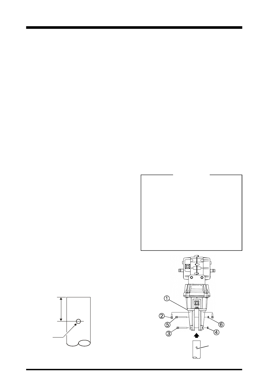
Mast Bracket Attachment in the Azimuth Rotator & Antenna Positioning
Important!! Before mounting the mast to the
azimuth rotator, a single hole must be drilled
through the bottom of the mast to accommo-
date an anti-twist support bolt used in the base
support bracket halves:
1.
Drill a 9 mm diameter hole through both
walls of the mast, centered 50 mm from
the mast bottom (see Figure 1). Ensure the
drill is maintained perpendicular and cen-
tered when making the hole, to ensure
proper alignment of the holes in the mast
and those in the base support clamp.
2.
Referring to Figure 2, loosely fasten the
mast bracket halves
À
to the rotator hous-
ing using four M8x25 bolts
Á
, flat wash-
ers and spring washers.
3.
Insert the mast into the bracket, and fin-
ger-tighten the four M8x70 bolts
Â
with
spring washers and nuts
Ã
. Note that one
side of the bracket has ridges on either side
of the bolt holes: the bolts should be in-
serted from this side, so the ridges hold the
bolt head from turning.
4.
Finger-tighten the M8x95 socket bolt
Ä
with nut
Å
.
5.
With the rotator connected, set the control-
ler so that it indicates precisely 0° (North).
Then, using an accurate map and known
landmarks, position the antenna (without
using the controller) so that it points to true
North. Alternatively, consult a Geodetic
Survey map for your area to determine the
MAST
9 ø
50mm
Figure 1
Figure 2
MAST
Magnetic Deviation at your location, and
then use a compass to position the antenna
so that it points to true North (Magnetic
North + Magnetic Deviation). Be careful
not to disturb the antenna direction when
tightening the mast bracket in the next step.
6.
When you are satisfied with the orienta-
tion of the antenna, center the mast on the
top of the azimuth rotator, and begin tight-
ening the M8x25 bolts
Á
on each side al-
ternately so that the gap on each side of
the mast remains the same. Markings are
provided on the top of the azimuth rotator
to assist this process.
7.
Confirm that the mast and bracket are pre-
cisely centered on the azimuth rotator, and
tighten the four bolts
Â
affixing the mast
bracket to the top of the azimuth rotator.
Warning !!
m Take care not overtighten the four
bracket bolts. Do not torque the bolts
beyond the point where the spring
washer flattens.
m The azimuth rotator is designed for ver-
tical mounting only. One half of the
housing is marked “TOP SIDE”. Wa-
ter and contaminants will damage the
motor unit if it is mounted horizontally
or upside-down.
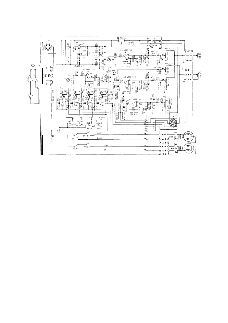
G-5500 Schematic Diagram

Copyright 1998
Yaesu Musen Co., Ltd.
All rights reserved.
No portion of this manual
may be reproduced without
the permission of
Yaesu Musen Co., Ltd.
Printed in Japan.
E12901000
Wyszukiwarka
Podobne podstrony:
YAESU G 250 ROTATOR User Manual
YAESU FT 411mkII User manual
YAESU VX 8R User Manual
YAESU VX 8R User Manual
YAESU ROTATOR G 400 User Manual
YAESU CAT GS 232A User Manual
cas test platform user manual
CARPROG Opel ECU programmer user manual
elm327 interface viecar obd2 bluetooth scanner user manual
autel power scan ps100 user manual
Chartplanner user manual
INPA User manual
all100 user manual
CARPROG user manual
FX2N 485 BD User's Manual JY992 Nieznany
mb sbc tool user manual
07 Altistart48 user manual
iphone user manual pdf
PRDM 0010 Upgrade user manual UPG 0001
więcej podobnych podstron