GS-232A
Computer Control Interface
for Antenna Rotators
YAESU MUSEN CO., LTD.
4-8-8 Nakameguro, Meguro-Ku, Tokyo 153-8644, Japan
YAESU U.S.A.
17210 Edwards Rd., Cerritos, CA 90703, U.S.A.
YAESU EUROPE B.V.
P.O. Box 75525 1118 ZN, Schiphol, The Netherlands
YAESU UK LTD.
Unit 12, Sun Valley Business Park, Winnall Close
Winchester, Hampshire, SO23 0LB, U.K.
YAESU GERMANY GmbH
Am Kronberger Hang 2, D-65824 Schwalbach, Germany
YAESU HK LTD.
11th Floor Tsim Sha Tsui Centre, 66 Mody Rd.,
Tsim Sha Tsui East, Kowloon, Hong Kong

1
GS-232A Computer Control Interface
for Yaesu Antenna Rotators
The GS-232A provide digital control of most models of
Yaesu antenna rotators
ø
from the serial port of an external
personal computer.
The GS-232A contains its own microprocessor with ROM
and RAM (memory), and a l0-bit analog-to-digital (A-D)
converter. The 3-wire async serial line can be configured for
serial data rates from 150 to 9600 baud. The GS-232A has a
DB-9 “male” connector for connection to the (RS-232C)
COM port of your computer. Purchase or construnct a
“straight” type serial cable, ensuring it has the correct gen-
der and number of pins for connection to your system.
Firmware on the GS-232A supports either direct keyboard
control, or commands from programs written specifically to
support it (software is not supplied by Yaesu). In addition
to reading and setting antenna angle and rotation speed,
the firmware includes clocked positioning routines to auto-
G
ENERAL
D
ESCRIPTION
matically step the antenna through up to 3800 angles at
programmable intervals, such as for tracking band open-
ings or satellites (with an elevation rotator).
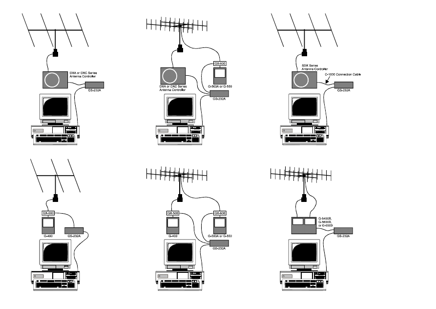
Please read this manual carefully to install the GS-232A. If
also installing a G-400, G-500A or G-550 with the GX-500
Automatic Control Adapter, follow the procedures in the
GX-500 manual before installing the GS-232A.
ø G-800DXA/G-1000DXA/G-2800DXA Azimuth Rotator,
G-800DXC/G-1000DXC/G-2800DXC Azimuth Rotator,
G-400 Azimuth Rotator,
G-500A/G-550 Elevation Rotator,
G-5400B/G-5600B/G-5500 A
Z
-E
L
Rotator, and
above Azimuth and Elevation rotator combination.
G-400 Azimuth Rotator and G-500A/G-550 Elevation Rotator requires
one GX-500 Automatic Control Adapter each.

2
G
ENERAL
Power Requirements:
DC 12 V, 110 mA
Case Size:
110 (W) x 21 (H) x 138 (D) mm
Weight (approx.):
380 g
Semiconductors
Microprocessor: HD6303XP
ROM:
27C64
RAM:
6264
A/D Converter:
HD46508PA (10 bits)
Serial Comms:
3-wire Async. DCE
RS-232C voltage levels,
150 to 9600 baud, 8 data bits,
1 stop bit, no parity, no handshake
S
PECIFICA
TIONS
C
ONNECTOR
P
INOUTS
Serial I/O:
9-pin DB-9 connector (RS-232C connector)
Pin 2 - Tx Data
Pin 3 - Rx Data
Pin 5 - Signal Ground
Rotator Control:
5-pin connector (EL connector)
Pin 1 - UP switch (open collector)
Pin 2 - DOWN switch (open collector)
Pin 3 - analog output (0.5 - 4.5 V, four steps)
Pin 4 - analog input (0-5V elevation)
Pin 5 - analog ground
5-pin connector (AZ connector)
Pin 1 - RIGHT switch (open collector)
Pin 2 - LEFT switch (open collector)
Pin 3 - analog output (0.5 - 4.5 V, four steps)
Pin 4 - analog input (0-5V azimuth)
Pin 5 - analog ground

3
S
UPPLIED
A
CCESSORIES
r Control cable for the Azimuth Rotator
ø1
................ 1 pc
(“5-pin”
1 “Min-DIN” cable)
r Control cable for the A
Z
/E
L
Rotator
ø2
.................... 1 pc
(“Dual 5-pin”
1 “DIN” cable)
r DC cable w/coaxial plug ......................................... 1 pc
r Hook & loop fasteners (for mounting) ................... 1 pc
ø1: G-5400B-G-5600B/G-5500
ø2: G-800DXA/G-1000DXA/G-2800DXA &
G-800DXC/G-1000DXC/G-2800DXC
A
CCESSORIES
& O
PTION
A
VAILABLE
O
PTIONS
GX-500
(GS-232A version)
Control Adapter
(Check with your dealer)
C-1000
Connection Cable
(for SDX series Azuimuth Rotator)
NC-72B/C/F/U
ø3
AC Adapter
ø3: “B” suffix is for use with 117 VAC,
“C” suffix is for use with 220-240 VAC,
“F” suffix is for use with 220 VAC, or
“U” suffix is for use with 230 VAC
4
During installation, a personal computer with a serial port
and terminal software is required to calibrate trimmers on
the Controller and on the Control Interface. Any simple in-
teractive terminal program can be used - it only has to trans-
mit keystrokes as typed, and display characters received
from the GS-232A.
I
NST
ALLA
TION
P
OWER
& C
ONTROL
C
ONNECTIONS
DXA or DXC Series Azimuth Rotator
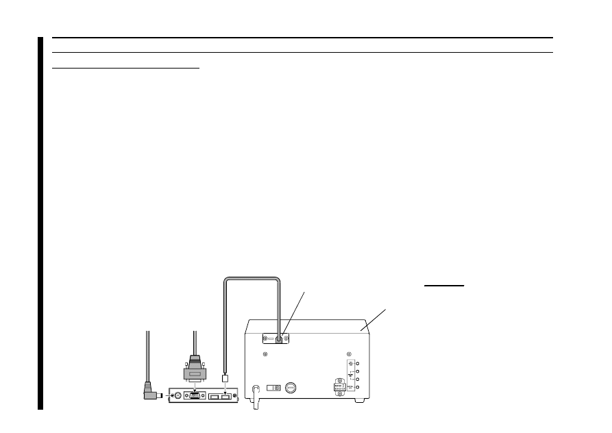
r Connect the supplied DC cable to a source of 12 VDC.
The red lead connects to the Positive (+) DC terminal,
and the black lead connects to the Negative
(–) DC terminal. The GS-232A requires 110 mA. The
supplied cable has a 500-mA fast-blow fuse. Use only
the same type fuse for replacement.
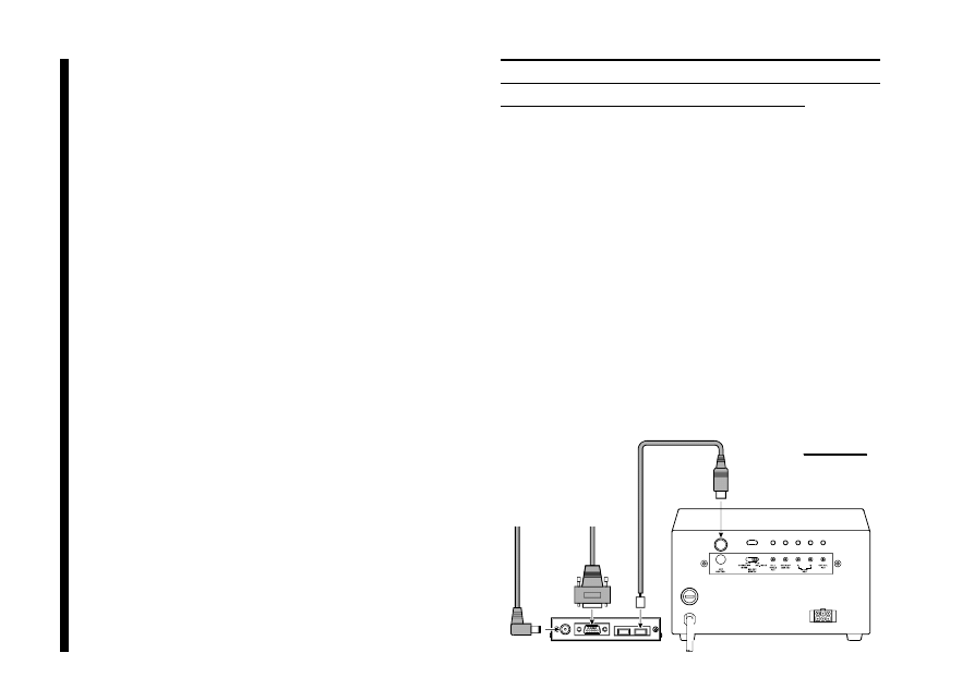
r Plug the coaxial power connector into the DC 12V jack
on the GS-232A rear panel.
r Connect the supplied Control cable (“5-pin” 1 “Mini-
DIN”) between the EXT CONTROL connector on the
rotator’s controller and AZ connector on the rear panel
of the GS-232A (Figure 1).
To DC 12V Power Source
To Serial port of the computer
DXA or DXC series
Azimuth Rotator
Figure 1
5
I
NST
ALLA
TION
G-5400B/-5600B Az-E
L
Rotator
r Connect the supplied DC cable to a source of 12 VDC.
The red lead connects to the Positive (+) DC terminal,
and the black lead connects to the Negative
(–) DC terminal. The
GS-232A requires 110 mA. The
supplied cable has a 500-mA fast-blow fuse. Use only
the same type fuse for replacement.
r Plug the coaxial power connector into the DC 12V jack
on the GS-232A rear panel.
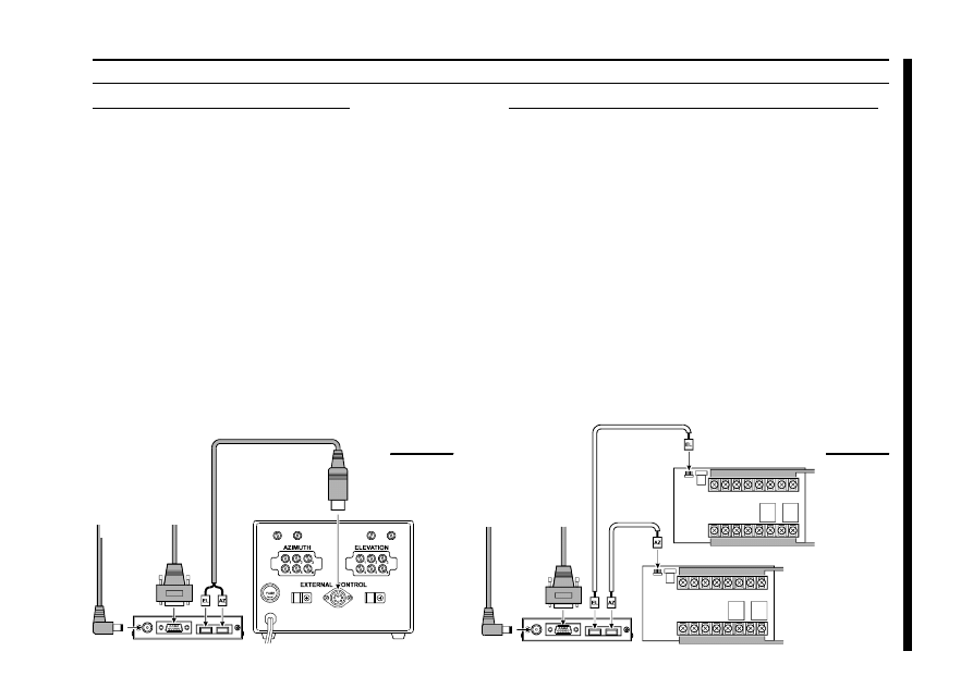
r Connect the supplied Control cable (“Dual 5-pin” 1
“DIN”) between the rotator’s controller and GS-232A.
Be careful to match the “AZ” and “EL” labels on the cable
with the same labels on the rear panel of the GS-232A
(Figure 2).
G-400/G-500 or G-400/G-550 & pair of GX-500
r Connect the supplied DC cable to a source of 12 VDC.
The red lead connects to the Positive (+) DC terminal,
and the black lead connects to the Negative
(–) DC terminal. The GS-232A requires 110 mA. The
supplied cable has a 500-mA fast-blow fuse. Use only
the same type fuse for replacement.
r Plug the coaxial power connector into the DC 12V jack
on the GS-232A rear panel.
r Connect the 5-pin to 5-pin cable (supplied with the GX-
500; requires two sets) between the GX-500(s) and GS-
232A (Figure 3).
P
OWER
& C
ONTROL
C
ONNECTIONS
GX-500
Figure 3
To DC 12V Power Source
To Serial port of the computer
To Elevation
Controller
To Elevation
Rotator
To Azimuth Controller
To Azimuth Rotator
GX-500
Figure 2
To DC 12V Power Source
To Serial port
of the computer
G-5400B/-5600B
or G-5500
A
Z
/E
L
Rotator
6
SDX Series Azimuth Rotator
r Prepare the optional C-1000 Connection Cable.
r Remove the Top cover from the controller.
r Connect the 8-pin connector of the C-1000 Connection
cable to the exposed 8-pin connector located the rear
left corner in the controller.
r Route the 5-pin connector of the C-1000 Connection
cable through out the rubber grommet on the rear panel
of the controller, and connect it to the AZ connector on
the rear panel of the GS-232A (Figure 4).
r Replace the Top Cover.
P
OWER
& C
ONTROL
C
ONNECTIONS
r Connect the supplied DC cable to a source of 12 VDC.
The red lead connects to the Positive (+) DC terminal,
and the black lead connects to the Negative
(–) DC terminal. The GS-232A requires 110 mA. The
supplied cable has a 500-mA fast-blow fuse. Use only
the same type fuse for replacement.
r Plug the coaxial power connector into the DC 12V jack
on the GS-232A rear panel.
I
NST
ALLA
TION
To DC 12V Power Source
To Serial port of the computer
SDX series
Azimuth Rotator
Figure 4
Output Grommet for
C-1000 Connection Cable
Exposed 8-pin Connector
(Inside of the Controller)
Optional C-1000 Connection Cable
7
C
OMPUTER
C
ONNECTION
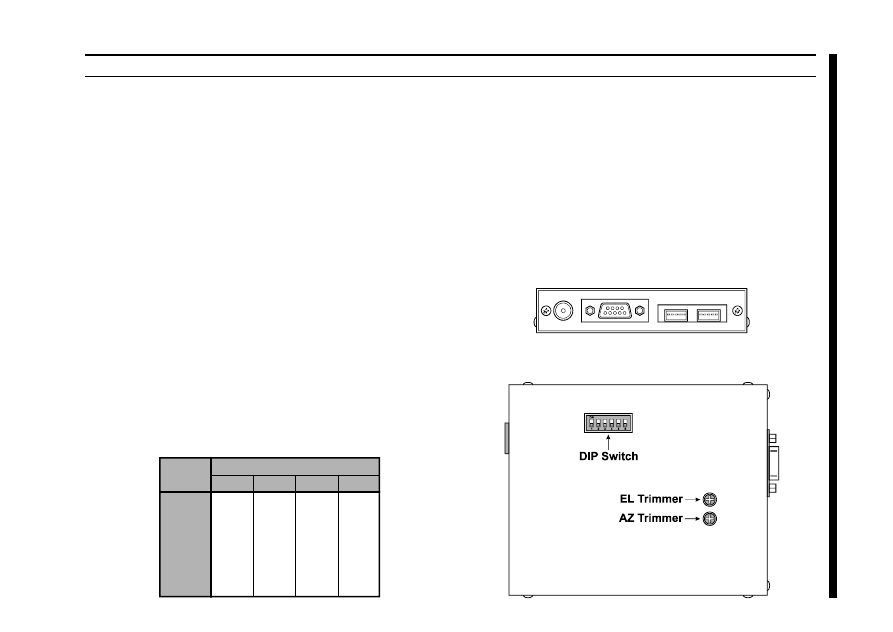
Baud Setting DIP Switches
GS-232A Bottom Case
r With the computer switched off, connect the RS-232C
cable to the serial port of the computer, then connect the
other end of your serial cable to the RS-232C connec-
tor on the rear panel of the GS-232A. Only three wires
are used for serial control, so there is no hardware hand-
shaking.
r If you are using a G-400 Azimuth Rotator, or G-5400B/
G-5600B A
Z
-E
L
Rotator, set the GS-232A’s DIP switch
(switch 5) to “OFF” position, to disable the 450° rotate
operation. If you are using a other rotators (except the
G-400/G-5400B and G-5600B), the GS-232A’s DIP
switch (switch 5) is still “ON.”
1
ON
OFF
ON
ON
ON
OFF
ON
150
300
600
1200
2400
4800
9600
2
ON
ON
OFF
ON
ON
OFF
ON
3
ON
ON
ON
OFF
ON
ON
OFF
4
ON
ON
ON
ON
OFF
ON
OFF
DIP Switch
Baud
I
NST
ALLA
TION
GS-232A Rear Panel
r Select the desired data baud rate with the DIP switch
bank on the GS-232A’s bottom case.
r The Control Interface serial data format uses 8 data bits,
no parity, and one stop bit, with no handshaking. Turn
on the computer, controller, and GS-232A, and set up
your terminal program for this format and your selected
data rate on the serial port to be used for rotator control.
8
DXA/DXC/SDX
SERIES
A
ZIMUTH
R
OTATOR
C
ALIBRA
TION
Azimuth Offset Null
r Before calibrate the Rotator, check to see that the GS-
232A’s DIP switch (switch 5) must be “ON” position.
r From the Controller panel, set the Rotator fully counter-
clockwise (set to 0°).
r Press [O] Ž [↵] (the letter “oh”, and “E
NTER
”) on the
computer keyboard to activate the azimuth calibration
routine. The computer display should show AZaaaa =
bbbb returned from the Interface Board, where aaaa
and bbbb are four-digit numbers padded at the left with
zeroes.
r Adjust the AZ trimmer (located on the bottom case of
the GS-232A) while watching the computer display, until
the four-digit numbers aaaa and bbbb are the same
(the precise values are not important).
r Turn off the GS-232A’s POWER switch to exit the azi-
muth calibration routine, then turn on the GS-232A’s
POWER switch again.
Azimuth A-D Calibration
r From the Controller panel, set the Rotator fully clock-
wise (to the right).
r Press [F] Ž [↵] (“F” and “E
NTER
”) on the computer key-
board to activate the Control Interface’s azimuth A-D
converter calibration routine. The computer’s display
should show +aaaa, where aaaa is a four-digit num-
ber which indicates the azimuth heading in degrees.
r Adjust the OUT VOL ADJ potentiometer on Controller
rear panel so as to get a reading of “0450” on the
computer’s display. This reading (“450 degrees”) corre-
sponds to the actual beam heading you established when
you pointed the azimuth rotator to the East.
r Turn off the GS-232A’s POWER switch to exit the azi-
muth A-D converter calibration routine, then turn on the
GS-232A’s POWER switch again.
Imprtant Note !
If your controller’s indicator needle starts from the point except 0° (North) (such as the default setting of the USA
version), align the starting point of the controller’s indicator needle to 0° (North) before calibration.
When finish the calibration, set the controller’s indicator needle to the desired point. Refer to the rotator’s user manual
for details regarding the indicator needle alignment.

9
G-400 A
ZIMUTH
R
OTATOR
C
ALIBRA
TION
Azimuth Offset Null
r Before calibrating the Rotator, check to see that the GS-
232A’s DIP switch (switch 5) is set to the “OFF” posi-
tion.
r From the Controller panel, set the Rotator fully counter-
clockwise (set to 180°).
r Press [O] Ž [↵] (the letter “oh”, and “E
NTER
”) on the
computer keyboard to activate the azimuth calibration
routine. The computer display should show AZaaaa =
bbbb returned from the Interface Board, where aaaa
and bbbb are four-digit numbers padded at the left with
zeroes.
r Adjust the AZ trimmer (located on the bottom case of
the GS-232A) while watching the computer display, until
the four-digit numbers aaaa and bbbb are the same
(the precise values are not important).
r Turn off the GS-232A’s POWER switch to exit the azi-
muth calibration routine, then turn on the GS-232A’s
POWER switch again.
Azimuth A-D Calibration
r From the Controller panel, set the Rotator fully clock-
wise (to the right).
r Press [F] Ž [↵] (“F” and “E
NTER
”) on the computer key-
board to activate the Control Interface’s azimuth A-D
converter calibration routine. The computer’s display
should show +aaaa, where aaaa is a four-digit num-
ber which indicates the azimuth heading in degrees.
r Adjust the FULL SCALE ADJ on the GX-500 so as to
get a reading of “0180” on the computer’s display.
This reading (“180 degrees”) corresponds to the actual
beam heading you established when you pointed the
azimuth rotator to the South (the fully clockwise set-
ting).
r Turn off the GS-232A’s POWER switch to exit the azi-
muth A-D converter calibration routine, then turn on the
GS-232A’s POWER switch again to turn it back on.

10
C
ALIBRA
TION
G-5400B/-5600B A
Z
-E
L
R
OTATOR
Azimuth Offset Null
r Before calibrating the Rotator, check to see that the GS-
232A’s DIP switch (switch 5) is set to the “OFF” posi-
tion.
r From the Controller panel, set the Azimuth Rotator fully
counter-clockwise (set to 180°).
r Press [O] Ž [↵] (the letter “oh”, and “E
NTER
”) on the
computer keyboard to activate the azimuth calibration
routine. The computer display should show AZaaaa =
bbbb returned from the Interface Board, where aaaa
and bbbb are four-digit numbers padded at the left with
zeroes.
r Adjust the AZ trimmer (located on the bottom case of
the GS-232A) while watching the computer display, until
the four-digit numbers aaaa and bbbb are the same
(the precise values are not important).
r Turn off the GS-232A’s POWER switch to exit the azi-
muth calibration routine, then turn on the GS-232A’s
POWER switch again.
Azimuth A-D Calibration
r From the Controller panel, set the Azimuth Rotator fully
clockwise (to the right).
r Press [F] Ž [↵] (“F” and “E
NTER
”) on the computer key-
board to activate the Control Interface’s azimuth A-D
converter calibration routine. The computer’s display
should show +aaaa, where aaaa is a four-digit num-
ber which indicates the azimuth heading in degrees.
r Adjust the OUT VOL ADJ potentiometer on the “A
ZI
-
MUTH
” (left) side of the Controller rear panel so as to get
a reading of “0180” on the computer’s display. This
reading (“180 degrees”) corresponds to the actual beam
heading you established when you pointed the azimuth
rotator to the South.
r Turn off the GS-232A’s POWER switch to exit the azi-
muth A-D converter calibration routine, then turn on the
GS-232A’s POWER switch again.

11
Elevation Offset Null
r From the Controller panel, set the Elevation Rotator to
the “left” horizon (down, set to 0°).
r Press [O2] Ž [↵] (the letter “oh,” “2,” and “E
NTER
”) on
the computer keyboard to activate the elevation calibra-
tion routine. The computer will return AZaaaa = bbbb,
as in the previous procedure, plus ELcccc = dddd to
the right, where cccc and dddd are four-digit numbers
padded at the left with zeroes.
r Adjust the EL trimmer (located on the bottom case of
the GS-232A), so as to make the numbers cccc and
dddd are the same (again, the actual values are unim-
portant).
r Turn off the GS-232A’s POWER switch to exit the el-
evation calibration routine, then turn on the GS-232A’s
POWER switch again to turn it back on.
C
ALIBRA
TION
Elevation A-D Calibration
r From the Controller panel, set the Elevation Rotator to
full scale (180°: “right” horizon).
r Press [F2] Ž [↵] (F, 2, and E
NTER
) on the computer key-
board to activate the Control Interface’s elevation A-D
converter calibration routine. The computer will display
+aaaa+eeee, where eeee is a four-digit number which
indicates the elevation heading in degrees. For the pur-
poses of this alignment, you may ignore the (azimuth)
aaaa numbers.
r Adjust the OUT VOL ADJ potentiometer on the “E
L
-
EVATION
” (right) side of the Controller rear panel so as to
get a reading of “0180” on the computer’s display.
This reading (“180 degrees”) corresponds to the actual
beam heading you established when you pointed the
elevation rotator to the 180° position.
r Turn off the GS-232A’s POWER switch to exit the el-
evation A-D converter calibration routine, then turn on
the GS-232A’s POWER switch again to turn it back on.
G-5400B/-5600B A
Z
-E
L
R
OTATOR

12
C
ALIBRA
TION
G-5500 A
Z
-E
L
R
OTATOR
Azimuth Offset Null
r Before calibrating the Rotator, check to see that the GS-
232A’s DIP switch (switch 5) is set to the “ON” posi-
tion.
r From the Controller panel, set the Rotator fully counter-
clockwise (set to 0°).
r Press [O] Ž [↵] (the letter “oh”, and “E
NTER
”) on the
computer keyboard to activate the azimuth calibration
routine. The computer display should show AZaaaa =
bbbb returned from the Interface Board, where aaaa
and bbbb are four-digit numbers padded at the left with
zeroes.
r Adjust the AZ trimmer (located on the bottom case of
the GS-232A) while watching the computer display, until
the four-digit numbers aaaa and bbbb are the same
(the precise values are not important).
r Turn off the GS-232A’s POWER switch to exit the azi-
muth calibration routine, then turn on the GS-232A’s
POWER switch again.
Azimuth A-D Calibration
r From the Controller panel, set the Azimuth Rotator fully
clockwise (to the right).
r Press [F] Ž [↵] (F and E
NTER
) on the computer keyboard
to activate the Control Interface’s azimuth A-D converter
calibration routine. The computer’s display should show
+aaaa, where aaaa is a four-digit number which indi-
cates the azimuth heading in degrees.
r Adjust the OUT VOL ADJ potentiometer on the “A
ZI
-
MUTH
” (left) side of the Controller rear panel so as to get
a reading of “0450” on the computer’s display. This
reading (“0450: 360 degrees + 90 degrees”) corre-
sponds to the actual beam heading you established when
you pointed the azimuth rotator fully clockwise.
r Turn off the GS-232A’s POWER switch to exit the azi-
muth A-D converter calibration routine, then turn on the
GS-232A’s POWER switch again.

13
Elevation Offset Null
r From the Controller panel, set the Elevation Rotator to
the “left” horizon (down, set to 0°).
r Press [O2] Ž [↵] (the letter “oh,” “2,” and “E
NTER
”) on
the computer keyboard to activate the elevation calibra-
tion routine. The computer will return AZaaaa = bbbb,
as in the previous procedure, plus ELcccc = dddd to
the right, where cccc and dddd are four-digit numbers
padded at the left with zeroes.
r Adjust the EL trimmer (located on the bottom case of
the GS-232A), so as to make the numbers cccc and
dddd are the same (again, the actual values are unim-
portant).
r Turn off the GS-232A’s POWER switch to exit the el-
evation calibration routine, then turn on the GS-232A’s
POWER switch again to turn it back on.
C
ALIBRA
TION
Elevation A-D Calibration
r From the Controller panel, set the Elevation Rotator to
full scal (180°: “right” horizon).
r Press [F2] Ž [↵] (F, 2, and E
NTER
) on the computer key-
board to activate the Control Interface’s elevation A-D
converter calibration routine. The computer will display
+aaaa+eeee, where eeee is a four-digit number which
indicates the elevation heading in degrees. For the pur-
poses of this alignment, you may ignore the (azimuth)
aaaa numbers.
r Adjust the OUT VOL ADJ potentiometer on the “E
L
-
EVATION
” (right) side of the Controller rear panel so as to
get a reading of “0180” on the computer’s display.
This reading (“180 degrees”) corresponds to the actual
beam heading you established when you pointed the
elevation rotator to the 180° position.
r Turn off the GS-232A’s POWER switch to exit the el-
evation A-D converter calibration routine, then turn on
the GS-232A’s POWER switch again to turn it back on.
G-5500 A
Z
-E
L
R
OTATOR

14
G-500 E
LEVATION
R
OTATOR
Elevation Offset Null
r From the Controller panel, set the Elevation Rotator to
the “left” horizon (down, set to 0°).
r Press [O2] Ž [↵] (the letter “oh,” “2,” and “E
NTER
”) on
the computer keyboard to activate the elevation calibra-
tion routine. The computer will return AZaaaa = bbbb,
as in the previous procedure, plus ELcccc = dddd to
the right, where cccc and dddd are four-digit numbers
padded at the left with zeroes.
r Adjust the EL trimmer (located on the bottom case of
the GS-232A), so as to make the numbers cccc and
dddd are the same (again, the actual values are unim-
portant).
r Turn off the GS-232A’s POWER switch to exit the el-
evation calibration routine, then turn on the GS-232A’s
POWER switch again to turn it back on.
C
ALIBRA
TION
Elevation A-D Calibration
r From the Controller panel, set the Elevation Rotator to
full scale (180°: “right” horizon).
r Press [F2] Ž [↵] (F, 2, and E
NTER
) on the computer key-
board to activate the Control Interface’s elevation A-D
converter calibration routine. The computer will display
+aaaa+eeee, where eeee is a four-digit number which
indicates the elevation heading in degrees. For the pur-
poses of this alignment, you may ignore the (azimuth)
aaaa numbers.
r Adjust the OUT VOL ADJ potentiometer on the GX-
500 so as to get a reading of “0180” on the computer’s
display. This reading (“180 degrees”) corresponds to
the actual beam heading you established when you
pointed the elevation rotator to the 180° position.
r Turn off the GS-232A’s POWER switch to exit the el-
evation A-D converter calibration routine, then turn on
the GS-232A’s POWER switch again to turn it back on.

15
G
ENERAL
O
PERA
TION
After installation and calibration, the Control Interface can
accept commands entered directly from the keyboard, or
from a program written specifically to support it (not sup-
plied by Yaesu). For brief summaries of the commands rec-
ognized by the Control Interface, press [H] Ž [
↵] for a list
of azimuth commands, or [H2] Ž [
↵] for elevations com-
mands. Keep in mind that all commands require that the
E
NTER
key be pressed after the command letter (or “0Dh”
be sent by a control program), although we will not repeat
this when discussing the commands. Also note that any
command letter may be sent in either upper or lower case.
The info screens shown on the next page will be returned
by the Control Interface.
Most commands have two versions: one for azimuth, and
one for elevation. Commands are not echoed by the Control
Interface, but a carriage return character (“0Dh”) is returned
after every command, and also a line feed character (“0Ah”)
if the command invoked returned data. Invalid commands
cause “? >” to be returned and the input buffer cleared.
Note that all angles are in degrees, beginning with zero at
the most counterclockwise azimuth (or horizontal elevation).
Angles sent to the Control Interface must be 3 digits long
(left-zero-padded), and angles returned will, in some cases,
be 4 digits long with a leading “+0.”
If you wish, you can mount the GS-232A on top of your
Rotator Controller using the two supplied hook-and-loop
fastener strips. Just remove the backing from one side of
each strip, and press into place on the bottom of the GS-
232A. Then remove the backing from the other side, and
press the GS-232A into place on the Controller.

16
O
PERA
TION
C
OMMAND
L
IST
In the following command descriptions, the elevation ver-
sion of each command, where there is one, is shown in pa-
rentheses (but don’t type the parentheses). Remember that
elevation commands require the G-5400B, G-5600B or G-
5500 A
Z
/E
L
Rotators, or the GX-500 adapter and the G-
500 or G-550 Elevation Rotator.
0 (02)
Offset calibration for internal AZ (EL) trimmer potentiom-
eter: preset rotator manually fully counter-clockwise, send
command, and adjust trimmer on Control Interface until re-
turned values are equal. Turn off the GS-232A’s POWER
switch to store settings.
H (H2)
Returns list of commands (see page 19).
F (F2)
Full Scale Calibration: preset rotator manually to full scale,
send command, adjust OUT VOL ADJ trimmer on rear of
controller (or GX-500 elevation adapter) until the returned
data is “+0180 or +0450” (“+0nnn+0180” for eleva-
tion). Turn off the GS-232A’s POWER switch to save new
settings.
R (U)
Start turning the rotator to the right (up)
L (D)
Start turning the rotator to the left (down).
A (E)
Stop azimuth (elevation) rotation.
S
Stop: cancel current command before completion.
C (B)
Return current azimuth (elevation) angle in the form “+0nnn”
degrees.
C2
Return azimuth and elevation (“+0aaa+0eee”, where aaa
= azimuth, eee = elevation).
Xn
Select azimuth rotator turning speed, where n = l (slowest)
to 4 (fastest). This command can be issued during rotation,
and takes effect immediately. There is no equivalent for el-
evation.

17
Maaa
Turn to aaa degrees azimuth, where aaa is three digits be-
tween “000” and “360 or 450: vary according to con-
troller type.” Rotation starts.
Msss aaa bbb ccc
This command, together with the [T] command, provides
automatic, timed tracking of moving objects or propagation
by the Control Interface itself. This command stores the
time value sss seconds to wait between stepping from azi-
muth aaa to bbb, and then to ccc, etc. (from “2” to as many
as “3800” angles may be stored with one command).
Note that this command is completely different than the [T]
command with only one parameter: when multiple parameters
are present, the first one is interpreted by the Control Interface
as the rotation interval sss, not an angle. Valid ranges are
“001” to “999” for sss, and “000” to “360 or 450: vary
according to controller type” for the angles. When this com-
mand is sent, the parameters are stored in the Control Interface’s
RAM, and the rotator turns to angle aaa and waits for a subse-
quent [T] command to begin the actual stepping. All numbers
must be 3 digits, space-separated. Stored values remain in
effect until another [M] command is issued (this may have no
parameters, in which case the “? >” error prompt is returned,
but memories are still cleared), or until the controller is turned
off or by toggling the GS-232A off and on.
T
See the [M] (above) and the [W] (below) command. Start
automatic stepping routine (both azimuth and eievation):
turn rotator to next sequentially memorized azimuth (or az-el
pair, for the [W] command), wait sss seconds, and turn to
next angle (or pair), etc. This command works only if a long-
form [M] or [W] has been issued since power-up or the last
reset.
N
Return serial number of currently selected memorized point
[nnnn], and total number of memorized points [mmmm],
in the form +nnnn+mmmm. Must be proceeded by either
a long-form [M] or [W], and a T command. Used only dur-
ing stepping (see [T] command).
The meaning of a “point” in this command following an [M]
command is only an azimuth angle, so in this case nnnn
and mmmm can range up to “3800” (the limit of avail-
able RAM in the Control Interface). However, when eleva-
tion is involved, a “point” following a [W] command is rep-
resented by both an azimuth and an elevation angle, in which
case nnnn and mmmm can range up to only “1900,” since
each “point” is a pair of angles.
O
PERA
TION
C
OMMAND
L
IST

18
Elevation Control Commands
These commands are only for az-el operation. Note that an
azimuth angle must always be supplied when changing el-
evation, and that a setting point consists of a pair of angles.
Waaa eee
Turn to aaa degrees azimuth and eee degrees elevation,
where aaa is three digits between “000” and “360 or
450: vary according to controller type,” and eee is three
digits between “000” and “180.” Rotators respond im-
mediately.
Wsss aaa eee aaa sss ...
This command is similar to the [M] command: the first pa-
rameter is a time interval, and succeeding parameters are
angles. With this command, however, angles are in azimuth-
elevation pairs, each pair representing one antenna loca-
tion. At most “1900” pairs can be sent and stored in the
Control Interface. As with the other commands, the time
interval range is limited to “001” to “999” (seconds),
azimuth to “000” to “360 or 450: vary according to
controller type,” and elevation to “000” to “180.”
When this command is sent, the rotators turn to the first
aaa azimuth parameter and the first eee elevation param-
eter, and wait for a subsequent [T] command to begin the
actual stepping (to the next azimuth-elevation pair). Stored
values remain in effect until another [W] command is is-
sued (this may have no parameters, in which case the “? >”
error prompt is returned, but memories are still cleared), or
until the controller is turned off or by toggling the GS-
232A off and on.
O
PERA
TION
C
OMMAND
L
IST

19
C
OMMAND
L
IST
O
PERA
TION
Returned by [H] Command:
--------- - COMMAND LIST 1 ----------
R
Clockwise Rotation
L
Counter Clockwise Rotation
A
CW/CCW Rotation Stop
C
Antenna Direction Value
M
Antenna Direction Setting. MXXX
M
Time Interval Direction Setting.
MTTT XXX XXX XXX -- -
(TTT = Step value)
(XXX = Horizontal Angle)
T
Start Command in the time interval direction setting
mode.
N
Total number of setting angles in “M” mode and traced
number of all datas (setting angles)
X 1 Rotation Speed 1 (Horizontal) Low
X 2 Rotation Speed 2 (Horizontal) Middle 1
X 3 Rotation Speed 3 (Horizontal) Middle 2
X 4 Rotation Speed 4 (Horizontal) High
S
All Stop
O
Offset Calibration
F
Full Scale Calibration
Returned by [H2] Command:
--------- - HELP COMMAND 2 ----------
U
UP Direction Rotation
D
DOWN Direction Rotation
E
UP/DOWN Direction Rotation Stop
C 2 Antenna Direction Value
W Antenna Direction Setting.
WXXX YYY
W Time Interval Direction Setting.
WTTT XXX YYY XXX YYY ---
(TTT = Step value)
(XXX = Horizontal Angle)
(YYY = Elevation Angle)
T
Start Command in the time interval direction setting
mode.
N
Total number of setting angle in “W” mode and traced
number of all datas (setting angles)
S
All Stop
0 2 Offset Calibration
F2 Full Scale Calibration
B
Elevation Antenna Direction Value

20
N
OTE


Printed in Japan
Copyright 2000
Yaesu Musen Co., Ltd.
All rights reserved.
No portion of this manual
may be reproduced
without the permission of
Yaesu Musen Co., Ltd.
E
A
A
1
4
X
1
0
0
Wyszukiwarka
Podobne podstrony:
YAESU ROTATOR G 400 User Manual
YAESU FT 411mkII User manual
YAESU G 5500 ROTATOR User Manual
YAESU G 250 ROTATOR User Manual
YAESU VX 8R User Manual
YAESU VX 8R User Manual
cas test platform user manual
CARPROG Opel ECU programmer user manual
elm327 interface viecar obd2 bluetooth scanner user manual
autel power scan ps100 user manual
Chartplanner user manual
INPA User manual
all100 user manual
CARPROG user manual
FX2N 485 BD User's Manual JY992 Nieznany
mb sbc tool user manual
07 Altistart48 user manual
iphone user manual pdf
PRDM 0010 Upgrade user manual UPG 0001
więcej podobnych podstron