
2009 ACCESSORIES & EQUIPMENT
Heated Seats - Service Information - Grand Caravan, Town & Country
DESCRIPTION
DESCRIPTION
WARNING:
The front passenger seat assembly contains critical components that
affect the front passenger airbag deployment. Correctly functioning front
passenger seat components are critical for the Occupant Classification
System (OCS) to properly classify the front passenger and calculate the
proper airbag deployment. Unapproved modifications or service
procedures to the front passenger seat assembly, its related components,
or trim cover may inadvertently change the airbag deployment in case of
a frontal crash. This could result in death or serious injury to the front
seat passenger if the vehicle is involved in an accident. The following
requirements must be strictly adhered to:
Do not modify the front passenger seat assembly or components in
any way.
Do not modify the front seat center console or center position seat
in any way.
Do not use prior or future model year seat trim covers not
designated for the specific model being repaired. Always use the
correct seat trim cover specified for the vehicle.
Do not replace the seat trim cover with an aftermarket trim cover.
Do not add a secondary trim cover other than those approved by
Chrysler/Mopar.
At no time should any Supplemental Restraint System (SRS)
component or SRS related component or fastener be modified or
replaced with any part except those which are approved by
Chrysler/Mopar.
2009 Dodge Grand Caravan SE
2009 ACCESSORIES & EQUIPMENT Heated Seats - Service Information - Grand Caravan, Town & Country
2009 Dodge Grand Caravan SE
2009 ACCESSORIES & EQUIPMENT Heated Seats - Service Information - Grand Caravan, Town & Country
steve
Monday, May 23, 2011 2:11:51 PM
Page 1
© 2006 Mitchell Repair Information Company, LLC.
steve
Monday, May 23, 2011 2:11:54 PM
Page 1
© 2006 Mitchell Repair Information Company, LLC.
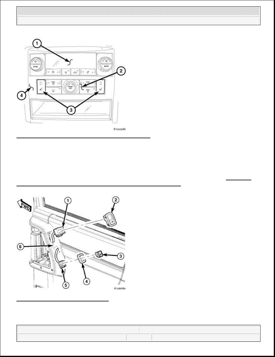
Fig. 1: Identifying Center Stack Rear HVAC Control Unit
Courtesy of CHRYSLER LLC
Vehicles with the heated seat option can be visually identified by the heated seat switches. Two heated seat
switches (3) for the front seats are located in the center stack (4) rear HVAC control unit (2). These two
switches allow the driver and front seat passenger to select from two different levels of electrical seat heating
(HI/LO). The front heated seat switches are an integral part of the HVAC control unit. If the switches are
inoperative or damaged in any way the complete HVAC control assembly must be replaced. See Electrical -
Heated/Cooled Systems/Heated Seats/SWITCH, Heated Seat - Removal.
Fig. 2: Identifying Heated Seat Switches
Courtesy of CHRYSLER LLC
Vehicles with the rear heated seat option can be visually identified by the two heated seat switches (3) located
in the sliding door trim panels (6). The sliding door trim panel mounted switches control the 2nd row heated
2009 Dodge Grand Caravan SE
2009 ACCESSORIES & EQUIPMENT Heated Seats - Service Information - Grand Caravan, Town & Country
steve
Monday, May 23, 2011 2:11:51 PM
Page 2
© 2006 Mitchell Repair Information Company, LLC.

seats. These switches allow the 2nd row seat passengers to select from two different levels of electrical seat
heating (HI/LO). The 2nd row heated seat switches are available individually for service. If the switches are
inoperative or damaged in any way they should be replaced. See Electrical - Heated/Cooled Systems/Heated
Seats/SWITCH, Heated Seat - Removal.
The heated seat system for this vehicle includes the following major components:
Heated Seat Elements - Eight carbon fiber heated seat elements are used per vehicle, two for each heated
seat. Two heated seat elements are integral to each seat, one in the seat back and the other in the seat
cushion.
Heated Seat Module - One heated seat module is used per vehicle. The Heated Seat Module is mounted
under the Driver front seat. This module contains the control logic and software for the front and 2nd row
heated seat system. The module communicates on the Local Interconnect Network (LIN) data bus.
Front Heated Seat Switches - Two heated seat switches for the front seats are located in the center stack
rear HVAC control unit. These two switches allow the driver and front seat passenger to select from two
different levels of electrical seat heating (HI/LO).
Rear Heated Seat Switches - Two heated seat switches for the rear seats are located in the sliding door
trim panels (6). The sliding door trim panel mounted switches control the 2nd row heated seats. These
switches allow the 2nd row seat passengers to select from two different levels of electrical seat heating
(HI/LO). The 2nd row heated seat switches are hardwired to the rear door modules.
Rear Door Modules - A door module is concealed behind the trim panel of each sliding door. The rear
door modules each utilize integrated circuitry and information carried on the CAN data bus network. In
regards to the 2nd row heated seat system, the modules communicate between the hardwired heated seat
switches and the instrument cluster. The cluster then transfers the information to the heated seat module.
Refer to Electrical - Electronic Control Modules/Electronic Control Modules/MODULE, Power
Liftgate Control - Description for additional information.
ElectroMechanical Instrument Cluster (EMIC) (also known as the Cab Compartment Node/CCN) -
The instrument cluster utilizes integrated software and information carried on the LIN and CAN data bus.
The instrument cluster serves as the link between the heated seat switches and the heated seat module.
For complete circuit diagrams, refer to SYSTEM WIRING DIAGRAMS for Town & Country and/or
SYSTEM WIRING DIAGRAMS for Grand Caravan . The wiring information includes wiring diagrams,
proper wire and connector repair procedures, details of wire harness routing and retention, connector pin-out
information and location views for the various wire harness connectors, splices and grounds.
OPERATION
OPERATION
CAUTION: On vehicles equipped with heated cloth seats the heating elements
are an integral part of the seat foam and cover. If the heating element
is damaged or inoperative the complete seat cushion/cover or seat
back/cover assembly must be replaced. Refer to the appropriate
procedures in BODY article .
2009 Dodge Grand Caravan SE
2009 ACCESSORIES & EQUIPMENT Heated Seats - Service Information - Grand Caravan, Town & Country
steve
Monday, May 23, 2011 2:11:51 PM
Page 3
© 2006 Mitchell Repair Information Company, LLC.

FRONT SEAT HEATED SEAT SYSTEM OPERATION
The front heated seat system operates on battery current received through a fuse in the Totally Integrated Power
Module (TIPM). Fused ignition switch output circuits are used, so that the systems will only operate when the
ignition switch is in the ON position. The heated seat system will turn off automatically whenever the ignition
switch is turned to any position except ON. If the ignition switch is turned to the OFF position while a heated
seat is on, the heated seat will remain off after the engine is restarted until a front seat heated seat switch is
depressed again. This prevents the vehicles battery from being drained by the heated seat system.
The heated seat switches for the front row seats are located in rear HVAC control assembly. The rear HVAC
control is mounted in the lower portion of the instrument panel center stack. Amber Light Emitting Diodes
(LEDS) in the top portion of each switch indicate the level of heat in use: Two LEDs are illuminated for high,
one for low, and none for off. Pressing the switch once will select high-level heating. Pressing the switch a
second time will select low-level heating. Pressing the switch a third time will shut the heating elements off.
A Heated Seat Module is used to control the heated seat system. The module is secured to a mounting bracket
located under the Driver front seat. The module responds to heated seat switch messages and ignition switch
status inputs by controlling the 12 v output to the seat heating elements through integral solid-state relays.
When either of the front heated seat switches are depressed a resistance signal is sent to the ElectroMechanical
Instrument Cluster (EMIC) (also known as the Cab Compartment Node/CCN). The instrument cluster receives
this message via the Controller Area Network (CAN) data bus. The instrument cluster then sends a message via
the Local Interconnect Network (LIN) data bus to the heated seat module, signaling the module to energize the
heating element for the selected seat.
The heated seat module energizes an integral solid-state relay, which supplies battery current to the heating
elements. Heated seats turn off after one hour of continuous operation. If high-level heating is selected, the
control system will remain at the high level for 30 minutes and then drop to the low level for 30 minutes. Then
it will turn off. At that time, the number of illuminated LEDs changes from two to one, indicating the change.
The module will automatically turn off the heating elements if it detects an OPEN or LOW short in the heating
element circuit.
2ND ROW HEATED SEAT SYSTEM OPERATION
The 2nd row heated seat system operates on battery current received through a fuse in the Totally Integrated
Power Module (TIPM). Fused ignition switch output circuits are used, so that the systems will only operate
when the ignition switch is in the ON position. The heated seat system will turn off automatically whenever the
ignition switch is turned to any position except ON. If the ignition switch is turned to the OFF position while a
heated seat is on, the heated seat will remain off after the engine is restarted until a 2nd row seat heated seat
switch is depressed again. This prevents the vehicles battery from being drained by the heated seat system.
The heated seat switches for the 2nd row seats are located in the sliding door trim panels near the door handles.
Amber Light Emitting Diodes (LEDS) in the top portion of each switch indicate the level of heat in use: Two
LEDs are illuminated for high, one for low, and none for off. Pressing the switch once will select high-level
heating. Pressing the switch a second time will select low-level heating. Pressing the switch a third time will
shut the heating elements off.
2009 Dodge Grand Caravan SE
2009 ACCESSORIES & EQUIPMENT Heated Seats - Service Information - Grand Caravan, Town & Country
steve
Monday, May 23, 2011 2:11:51 PM
Page 4
© 2006 Mitchell Repair Information Company, LLC.

The 2nd row heated seat system utilizes the same heated seat module as the front heated seat system. The
module is secured to a mounting bracket located under the Driver front seat. The module responds to heated
seat switch messages and ignition switch status inputs by controlling the 12 v output to the seat heating
elements through integral solid-state relays.
When either of the 2nd row heated seat switches are depressed a hardwired resistance signal is sent to the
applicable Rear Door Module (left or right). The applicable Rear Door Module then sends a message via the
Controller Area Network (CAN) data bus network to the ElectroMechanical Instrument Cluster (EMIC) (also
known as the Cab Compartment Node/CCN). The instrument cluster then sends a message via the Local
Interconnect Network (LIN) data bus to the heated seat module, signaling the module to energize the heating
element for the selected seat. Light Emitting Diodes (LED) in each switch indicate the level of heat in use. The
switch LEDs are controlled by the applicable Rear Door Module.
The heated seat module energizes an integral solid-state relay, which supplies battery current to the heating
elements. Heated seats turn off after one hour of continuous operation. If high-level heating is selected, the
control system will remain at the high level for 30 minutes and then drop to the low level for 30 minutes. Then
it will turn off. At that time, the number of illuminated LEDs changes from two to one, indicating the change.
The module will automatically turn off the heating elements if it detects an OPEN or LOW short in the heating
element circuit.
DIAGNOSIS AND TESTING
HEATED SEAT SYSTEM
PRELIMINARY CHECKS
Before testing the individual components in the heated seat system, check the following:
Check the vehicles battery open-circuit voltage and charging system performance. If the vehicle's
electrical system is defective or weak it may not be suppling sufficient energy to operate the heated seat
system.
Using a diagnostic scan tool, check for any heated seat system related Diagnostic Trouble Codes (DTCs).
Record these codes on paper for reference and resolve using the Appropriate Diagnostic Information.
If the front heated seat system functions properly but the heated seat switch HI/LO LED indicators do not
light with the ignition switch in the ON position and the heated seat switch in the low or high position,
check the fused ignition switch fuse in the totally integrated power module. If OK, replace the HVAC
control assembly. If not OK, repair the shorted circuit or component as required and replace the
inoperative fuse.
If the 2nd row heated seat system functions properly but the heated seat switch HI/LO LED indicators do
NOTE:
Vehicles equipped with the heated seat option utilize a low voltage cut-off
feature. This feature turns off power to the heated seat system anytime vehicle
voltage is below 11.7 V or above 15.5 V. Be certain to check the vehicle
electrical system for proper voltage anytime the power seat system appears
inoperative.
2009 Dodge Grand Caravan SE
2009 ACCESSORIES & EQUIPMENT Heated Seats - Service Information - Grand Caravan, Town & Country
steve
Monday, May 23, 2011 2:11:51 PM
Page 5
© 2006 Mitchell Repair Information Company, LLC.

not light with the ignition switch in the ON position and the heated seat switch in the low or high
position, check the fused ignition switch fuse in the totally integrated power module. If OK, replace the
suspect heated seat switch. If not OK, repair the shorted circuit or component as required and replace the
inoperative fuse.
SCAN TOOL DIAGNOSIS
The most reliable, efficient, and accurate means to diagnose the heated seat system requires the use of a
diagnostic scan tool and the Appropriate Diagnostic Information. The diagnostic scan tool can provide vital
information to the technician trying to find a problem with the heated seat system. Diagnostic logic is built into
the Heated Seat Module, Instrument Cluster and both Rear Door Modules to help locate the problem by the
most efficient means possible. Anytime a problem is suspected, a diagnostic scan tool should be obtained and
used to retrieve any heated seat system related stored fault codes.
If diagnostic fault codes are present in the module, record them on a piece of paper immediately before
proceeding any further. Then, use these fault codes to identify the problem by verifying the fault code.
Example, If the module records "DRIVER SEAT HEAT OUTPUT OPEN" fault code, locate the diagnostic
procedure for this code in the Appropriate Diagnostic Information and follow the flow chart until the specific
problem is located and resolved. Once the problem is thought to be corrected, erase the stored fault code using
the diagnostic scan tool and verify correct system operation. If the heated seat system is functioning correctly,
verify that there are no other stored codes and return the vehicle to service.
If the fault code could not be verified, this is a good indication that an INTERMITTENT problem may be
present. You must then attempt to find the intermittent problem, such as moving the heating element within the
seat while testing continuity or wiggling the wire harness/electrical connectors under the seat while testing
continuity.
For complete circuit diagrams, refer to SYSTEM WIRING DIAGRAMS for Town & Country and/or
SYSTEM WIRING DIAGRAMS for Grand Caravan . The wiring information includes wiring diagrams,
proper wire and connector repair procedures, details of wire harness routing and retention, connector pin-out
information and location views for the various wire harness connectors, splices and grounds.
CONTACT
DESCRIPTION
DESCRIPTION
2009 Dodge Grand Caravan SE
2009 ACCESSORIES & EQUIPMENT Heated Seats - Service Information - Grand Caravan, Town & Country
steve
Monday, May 23, 2011 2:11:51 PM
Page 6
© 2006 Mitchell Repair Information Company, LLC.
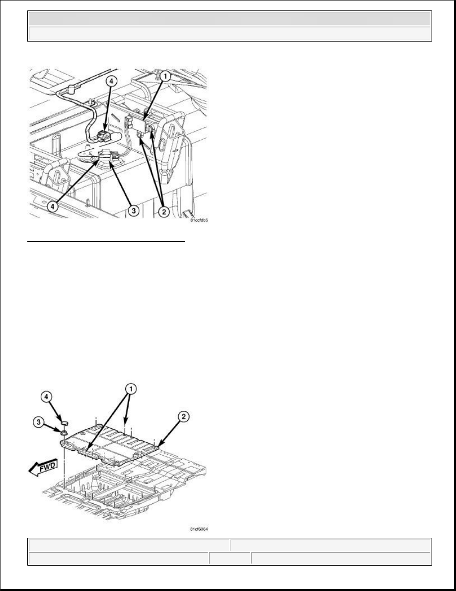
Fig. 3: Seat Contact Electrical Connector
Courtesy of CHRYSLER LLC
Vehicles equipped with 2nd row heated seats and the Swivel 'N Go® Seating System utilize a set of electrical
contacts for the seat wiring. One contact is fastened to the seat frame at the front inboard latching mechanism.
The other contact (1) is located on the inboard 2nd row seat striker. These contacts provide electrical current to
the seats for the 2nd row heated seat option while still allowing for complete seat removal from the vehicle. The
contacts automatically disengage or engage as the seat is removed or installed. The contacts slide past each
other as the seat is rolled to and from the strikers.
REMOVAL
REMOVAL
2009 Dodge Grand Caravan SE
2009 ACCESSORIES & EQUIPMENT Heated Seats - Service Information - Grand Caravan, Town & Country
steve
Monday, May 23, 2011 2:11:51 PM
Page 7
© 2006 Mitchell Repair Information Company, LLC.
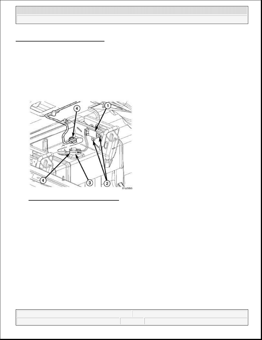
Fig. 4: Second Row Heated Seat Contact
Courtesy of CHRYSLER LLC
1. Disconnect and isolate the battery negative cable.
2. Remove the 2nd row seats.
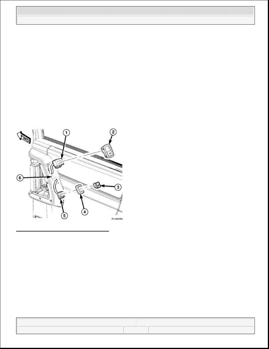
Fig. 5: Seat Contact Electrical Connector
Courtesy of CHRYSLER LLC
3. Remove the 2nd row floor trim ring (2).
a. Remove the retaining nut trim plugs (4).
b. Remove the retaining nuts (3).
c. Carefully remove the trim ring (2) from the vehicle.
4. Disconnect the seat contact electrical connector (4).
5. Using door trim panel tool C-4829A or equivalent, remove the wire harness routing clip (3) from the
vehicle floor.
6. Remove the two retaining screws (2).
7. Remove the contact assembly (1) from the vehicle.
INSTALLATION
INSTALLATION
CAUTION: The 2nd row floor trim ring may be damaged if excessively flexed or
twisted. Take care to support the complete assembly during removal
and installation.
2009 Dodge Grand Caravan SE
2009 ACCESSORIES & EQUIPMENT Heated Seats - Service Information - Grand Caravan, Town & Country
steve
Monday, May 23, 2011 2:11:51 PM
Page 8
© 2006 Mitchell Repair Information Company, LLC.
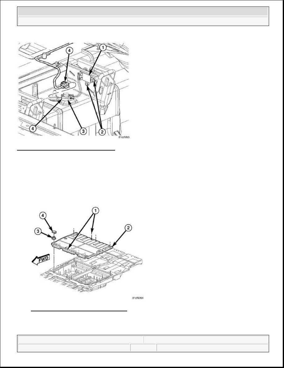
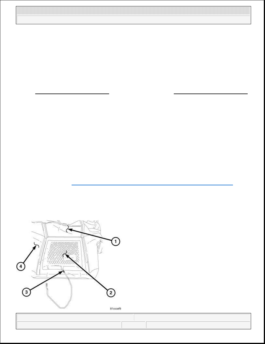
Fig. 6: Seat Contact Electrical Connector
Courtesy of CHRYSLER LLC
1. Position the 2nd row heated seat contact (1) into the vehicle.
2. Install the two retaining screws (2)
3. Secure the wire harness routing clip to the hole vehicle floor (3).
4. Connect the seat contact electrical connector (4).
Fig. 7: Second Row Heated Seat Contact
Courtesy of CHRYSLER LLC
CAUTION: The 2nd row floor trim ring may be damaged if excessively flexed or
2009 Dodge Grand Caravan SE
2009 ACCESSORIES & EQUIPMENT Heated Seats - Service Information - Grand Caravan, Town & Country
steve
Monday, May 23, 2011 2:11:51 PM
Page 9
© 2006 Mitchell Repair Information Company, LLC.
5. Install the 2nd row floor trim ring (2).
a. Position the trim ring (2) into the vehicle and align the holes with the weld studs on the vehicle
floor.
b. Ensure the 4-way locator at the front and 2-way locator at the rear of the panel are positioned
properly on the center seat tub reinforcement (1).
c. Install retaining nuts (3) starting with the center two front and rear nuts and working outward to
both edges of the panel.
d. Install the retaining nut trim plugs (4).
6. Install the 2nd row seats.
7. Connect the battery negative cable.
MODULE, HEATED SEAT
DESCRIPTION
DESCRIPTION
Fig. 8: Heated Seat Module
Courtesy of CHRYSLER LLC
The heated seat module (2) is located under the Driver front seat. It has a single electrical connector (1) and a
push pin style retainer that secures it to the seat pan. The module can be accessed from under the front Driver
seat with the seat in the full rearward position.
The heated seat module is a microprocessor designed to use the Local Interface Network (LIN) data bus
twisted. Take care to support the complete assembly during removal
and installation.
2009 Dodge Grand Caravan SE
2009 ACCESSORIES & EQUIPMENT Heated Seats - Service Information - Grand Caravan, Town & Country
steve
Monday, May 23, 2011 2:11:51 PM
Page 10
© 2006 Mitchell Repair Information Company, LLC.

messages from the instrument cluster also known as the Cabin Compartment Node (CCN). The CCN receives
inputs from the heated seat switches and rear door modules and in turn signals the heated seat module to operate
the heated seat elements for the appropriate seats.
OPERATION
OPERATION
FRONT SEAT HEATED SEAT SYSTEM OPERATION
The front heated seat system operates on battery current received through a fuse in the Totally Integrated Power
Module (TIPM). Fused ignition switch output circuits are used, so that the systems will only operate when the
ignition switch is in the ON position. The heated seat system will turn off automatically whenever the ignition
switch is turned to any position except On. If the ignition switch is turned to the OFF position while a heated
seat is on, the heated seat will remain off after the engine is restarted until a front seat heated seat switch is
depressed again. This prevents the vehicles battery from being drained by the heated seat system.
The heated seat switches for the front row seats are located in rear HVAC control assembly. The rear HVAC
control is mounted in the lower portion of the instrument panel center stack. Amber Light Emitting Diodes
(LEDS) in the top portion of each switch indicate the level of heat in use: Two LEDs are illuminated for high,
one for low, and none for off. Pressing the switch once will select high-level heating. Pressing the switch a
second time will select low-level heating. Pressing the switch a third time will shut the heating elements off.
A Heated Seat Module is used to control the heated seat system. The module is secured to a mounting bracket
located under the Driver front seat. The module responds to heated seat switch messages and ignition switch
status inputs by controlling the 12v output to the seat heating elements through integral solid-state relays.
When either of the front heated seat switches are depressed a resistance signal is sent to the ElectroMechanical
Instrument Cluster (EMIC) (also known as the Cab Compartment Node/CCN). The instrument cluster receives
this message via the Controller Area Network (CAN) data bus. The instrument cluster then sends a message via
the Local Interconnect Network (LIN) data bus to the heated seat module, signaling the module to energize the
heating element for the selected seat.
The heated seat module energizes an integral solid-state relay, which supplies battery current to the heating
elements. Heated seats turn off after one hour of continuous operation. If high-level heating is selected, the
control system will remain at the high level for 30 minutes and then drop to the low level for 30 minutes. Then
it will turn off. At that time, the number of illuminated LEDs changes from two to one, indicating the change.
The module will automatically turn off the heating elements if it detects an OPEN or LOW short in the heating
element circuit.
2ND ROW HEATED SEAT SYSTEM OPERATION
The 2nd row heated seat system operates on battery current received through a fuse in the Totally Integrated
Power Module (TIPM). Fused ignition switch output circuits are used, so that the systems will only operate
when the ignition switch is in the ON position. The heated seat system will turn off automatically whenever the
ignition switch is turned to any position except On. If the ignition switch is turned to the OFF position while a
heated seat is on, the heated seat will remain off after the engine is restarted until a 2nd row seat heated seat
2009 Dodge Grand Caravan SE
2009 ACCESSORIES & EQUIPMENT Heated Seats - Service Information - Grand Caravan, Town & Country
steve
Monday, May 23, 2011 2:11:51 PM
Page 11
© 2006 Mitchell Repair Information Company, LLC.

switch is depressed again. This prevents the vehicles battery from being drained by the heated seat system.
The heated seat switches for the 2nd row seats are located in the sliding door trim panels near the door handles.
Amber Light Emitting Diodes (LEDS) in the top portion of each switch indicate the level of heat in use: Two
LEDs are illuminated for high, one for low, and none for off. Pressing the switch once will select high-level
heating. Pressing the switch a second time will select low-level heating. Pressing the switch a third time will
shut the heating elements off.
The 2nd row heated seat system utilizes the same heated seat module as the front heated seat system. The
module is secured to a mounting bracket located under the Driver front seat. The module responds to heated
seat switch messages and ignition switch status inputs by controlling the 12 v output to the seat heating
elements through integral solid-state relays.
When either of the 2nd row heated seat switches are depressed a hardwired resistance signal is sent to the
applicable Rear Door Module (left or right). The applicable Rear Door Module then sends a message via the
Controller Area Network (CAN) data bus network to the ElectroMechanical Instrument Cluster (EMIC) (also
known as the Cab Compartment Node/CCN). The instrument cluster then sends a message via the Local
Interconnect Network (LIN) data bus to the heated seat module, signaling the module to energize the heating
element for the selected seat. Light Emitting Diodes (LED) in each switch indicate the level of heat in use. The
switch LEDs are controlled by the applicable Rear Door Module.
The heated seat module energizes an integral solid-state relay, which supplies battery current to the heating
elements. Heated seats turn off after one hour of continuous operation. If high-level heating is selected, the
control system will remain at the high level for 30 minutes and then drop to the low level for 30 minutes. Then
it will turn off. At that time, the number of illuminated LEDs changes from two to one, indicating the change.
The module will automatically turn off the heating elements if it detects an OPEN or LOW short in the heating
element circuit.
DIAGNOSIS AND TESTING
HEATED SEAT MODULE
PRELIMINARY CHECKS
Before testing the individual components in the heated seat system, check the following:
Check the vehicles battery open-circuit voltage and charging system performance. If the vehicle's
electrical system is defective or weak it may not be suppling sufficient energy to operate the heated seat
system.
Using a diagnostic scan tool, check for any heated seat system related Diagnostic Trouble Codes (DTCs).
NOTE:
Vehicles equipped with the heated seat option utilize a low voltage cut-off
feature. This feature turns off power to the heated seat system anytime vehicle
voltage is below 11.7 V or above 15.5 V. Be certain to check the vehicle
electrical system for proper voltage anytime the power seat system appears
inoperative.
2009 Dodge Grand Caravan SE
2009 ACCESSORIES & EQUIPMENT Heated Seats - Service Information - Grand Caravan, Town & Country
steve
Monday, May 23, 2011 2:11:51 PM
Page 12
© 2006 Mitchell Repair Information Company, LLC.

Record these codes on paper for reference and resolve using the Appropriate Diagnostic Information.
If the front heated seat system functions properly but the heated seat switch HI/LO LED indicators do not
light with the ignition switch in the ON position and the heated seat switch in the low or high position,
check the fused ignition switch fuse in the totally integrated power module. If OK, replace the HVAC
control assembly. If not OK, repair the shorted circuit or component as required and replace the
inoperative fuse.
If the 2nd row heated seat system functions properly but the heated seat switch HI/LO LED indicators do
not light with the ignition switch in the ON position and the heated seat switch in the low or high
position, check the fused ignition switch fuse in the totally integrated power module. If OK, replace the
suspect heated seat switch. If not OK, repair the shorted circuit or component as required and replace the
inoperative fuse.
SCAN TOOL DIAGNOSIS
The most reliable, efficient, and accurate means to diagnose the heated seat system requires the use of a
diagnostic scan tool and the Appropriate Diagnostic Information. The diagnostic scan tool can provide vital
information to the technician trying to find a problem with the heated seat system. Diagnostic logic is built into
the Heated Seat Module, Instrument Cluster and both Rear Door Modules to help locate the problem by the
most efficient means possible. Anytime a problem is suspected, a diagnostic scan tool should be obtained and
used to retrieve any heated seat system related stored fault codes.
If diagnostic fault codes are present in the module, record them on a piece of paper immediately before
proceeding any further. Then, use these fault codes to identify the problem by verifying the fault code.
Example, If the module records "DRIVER SEAT HEAT OUTPUT OPEN" fault code, locate the diagnostic
procedure for this code in the Appropriate Diagnostic Information and follow the flow chart until the specific
problem is located and resolved. Once the problem is thought to be corrected, erase the stored fault code using
the diagnostic scan tool and verify correct system operation. If the heated seat system is functioning correctly,
verify that there are no other stored codes and return the vehicle to service.
If the fault code could not be verified, this is a good indication that an INTERMITTENT problem may be
present. You must then attempt to find the intermittent problem, such as moving the heating element within the
seat while testing continuity or wiggling the wire harness/electrical connectors under the seat while testing
continuity.
For complete circuit diagrams, refer to SYSTEM WIRING DIAGRAMS for Town & Country and/or
SYSTEM WIRING DIAGRAMS for Grand Caravan . The wiring information includes wiring diagrams,
proper wire and connector repair procedures, details of wire harness routing and retention, connector pin-out
information and location views for the various wire harness connectors, splices and grounds.
REMOVAL
REMOVAL
2009 Dodge Grand Caravan SE
2009 ACCESSORIES & EQUIPMENT Heated Seats - Service Information - Grand Caravan, Town & Country
steve
Monday, May 23, 2011 2:11:51 PM
Page 13
© 2006 Mitchell Repair Information Company, LLC.

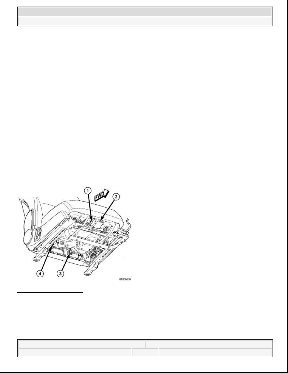
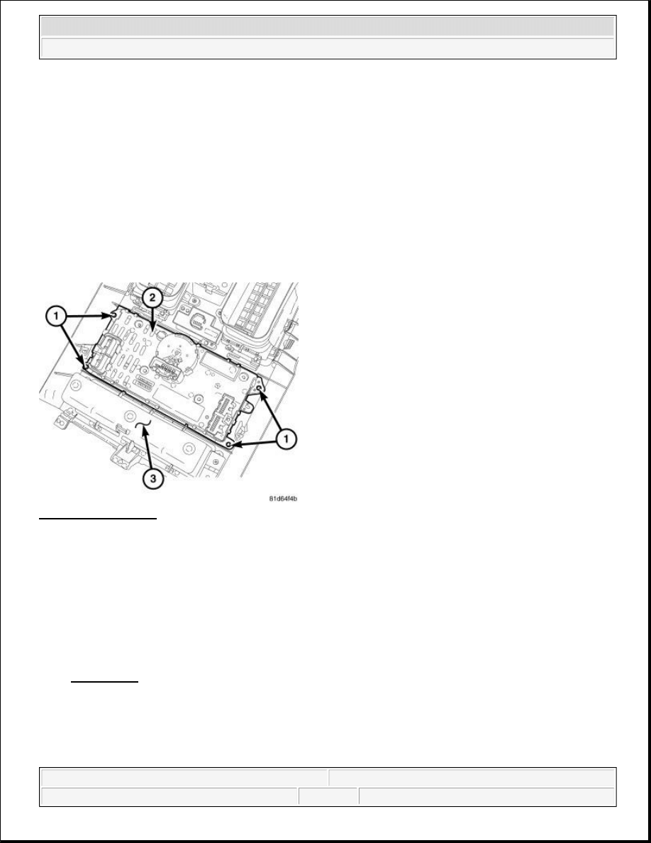
Fig. 9: Locating Heated Seat Module
Courtesy of CHRYSLER LLC
1. Position the Driver front seat to the full rearward position.
2. Disconnect and isolate the battery negative cable.
3. Disconnect the wire harness connector (4) from the heated seat module (3).
4. Unsnap the heated seat module retaining tab (2) from the seat pan (1).
5. Remove the heated seat module (3) from the vehicle.
INSTALLATION
INSTALLATION
CAUTION: The Heated Seat Module mounting tab can be damaged during module
removal and installation. Use care to properly align tab to prevent binding
that could result in tab breakage.
CAUTION: The Heated Seat Module mounting tab can be damaged during module
removal and installation. Use care to properly align tab to prevent binding
that could result in tab breakage.
2009 Dodge Grand Caravan SE
2009 ACCESSORIES & EQUIPMENT Heated Seats - Service Information - Grand Caravan, Town & Country
steve
Monday, May 23, 2011 2:11:51 PM
Page 14
© 2006 Mitchell Repair Information Company, LLC.
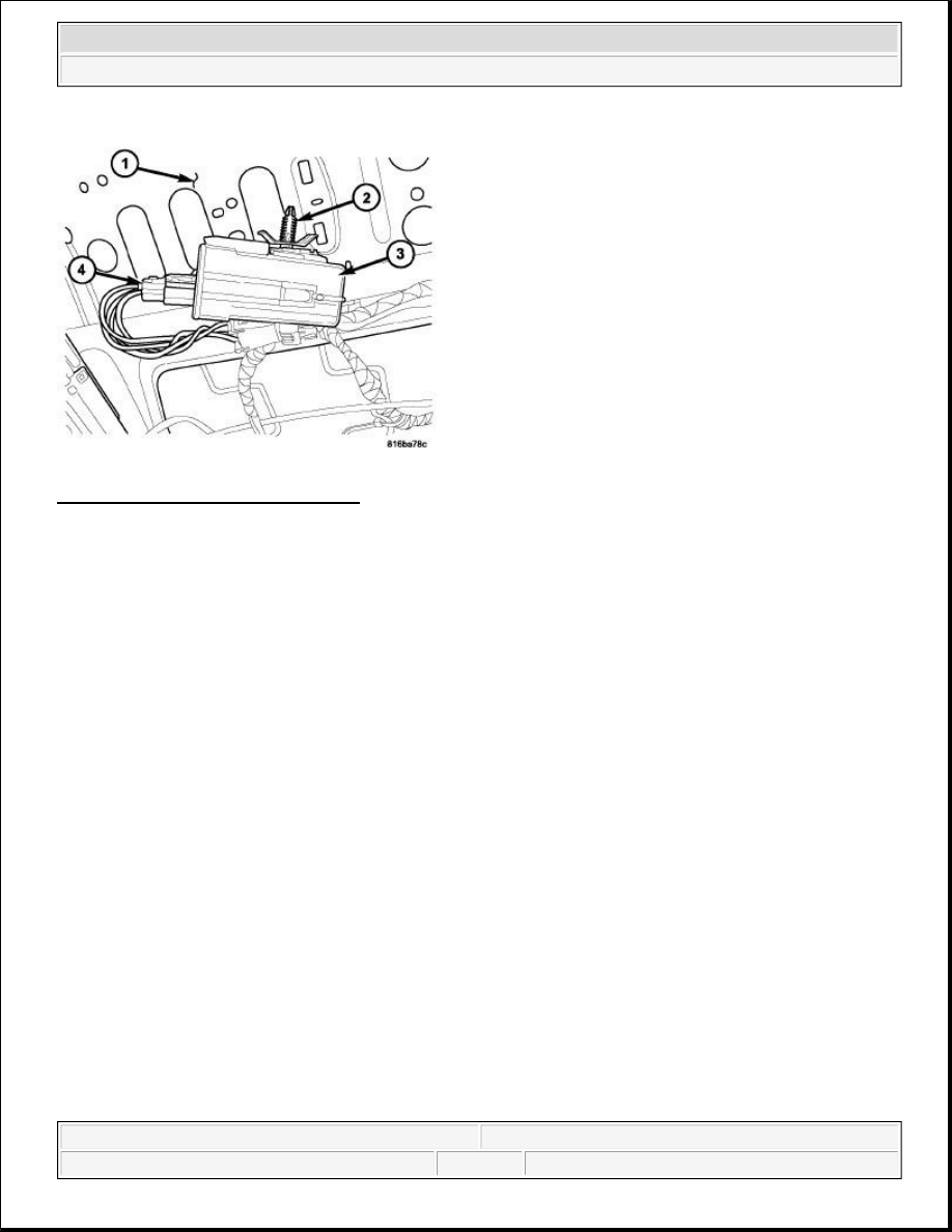
Fig. 10: Locating Heated Seat Module
Courtesy of CHRYSLER LLC
1. Install the heated seat module (3) into the vehicle.
2. Position the retaining tab (2) with the mounting hole in the seat pan (1). Firmly apply even pressure to the
module (3) until the mounting tab is fully seated.
3. Connect the wire harness connector (4) to the heated seat module (3).
4. Connect the battery negative cable.
5. Check for proper heated seat system operation.
PAD, HEATER
DESCRIPTION
DESCRIPTION
2009 Dodge Grand Caravan SE
2009 ACCESSORIES & EQUIPMENT Heated Seats - Service Information - Grand Caravan, Town & Country
steve
Monday, May 23, 2011 2:11:51 PM
Page 15
© 2006 Mitchell Repair Information Company, LLC.
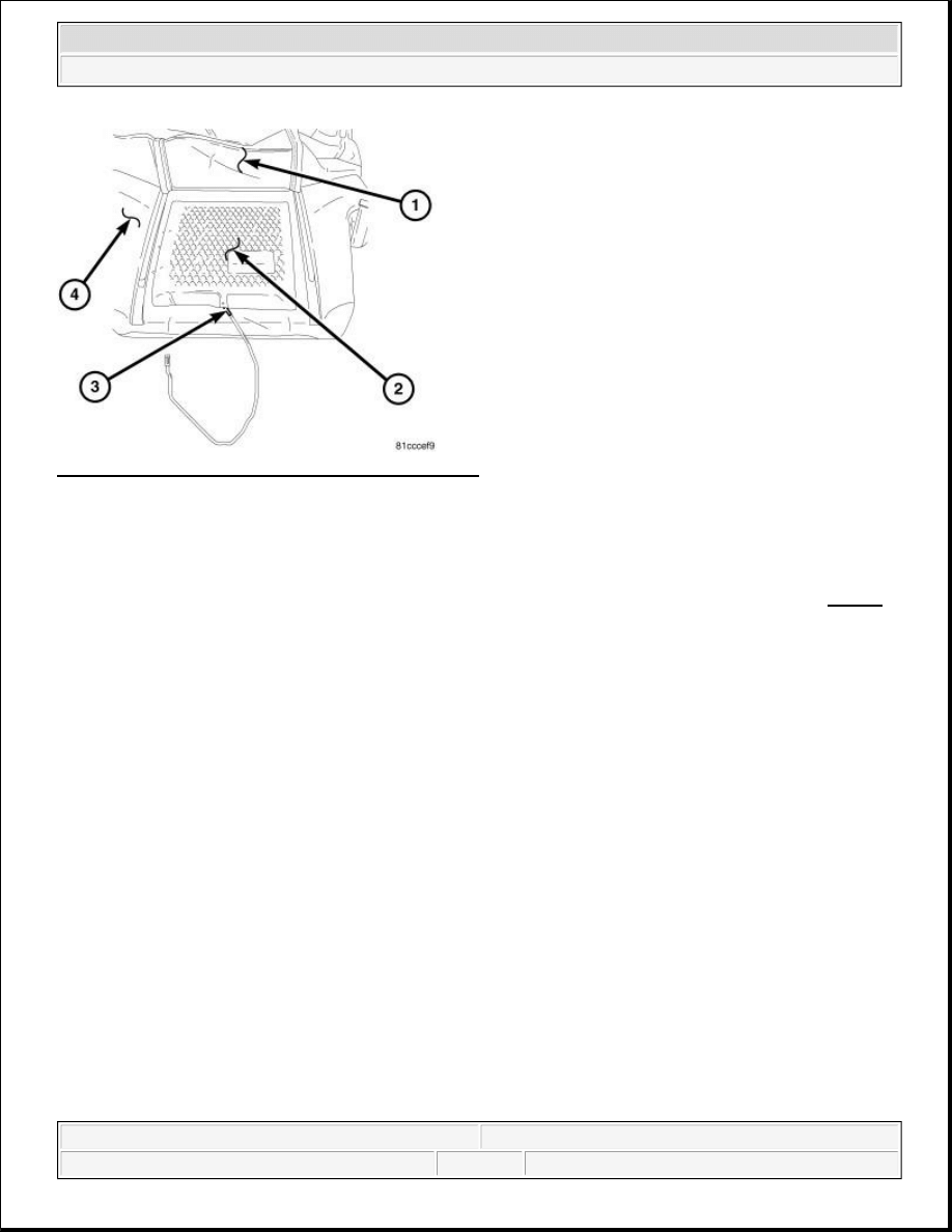
Fig. 11: Seat Back Heated Seat Element Components
Courtesy of CHRYSLER LLC
Vehicles equipped with the optional heated seat system have two, carbon fiber heated seat elements (2), located
in each front row and 2nd row seat. One heating element is used for each seat cushion and another for each seat
back.
Each of the heated seat element consists of multiple heating circuits operating in parallel throughout the carbon
fiber element. The heated seat elements are captured between the leather or cloth trim cover (1) and the seat
foam cushion assembly (4). If a malfunction occurs in one or more of the individual carbon fiber circuits, the
others will continue to provide heat.
The heated seat elements cannot be repaired. If found to be damaged or inoperative, a new heating element
assembly must be installed.
OPERATION
OPERATION
One end of the heated seat element is connected to ground at all times through a splice under the seat. Battery
current is directed to the other end of the heated seat element by the heated seat module. The heated seat module
will energize the heated seat element when the heated seat switch is depressed in the LOW or HIGH position.
CAUTION: On vehicles equipped with heated cloth seats the heating elements are an
integral part of the seat foam and cover. If the heating element is damaged
or inoperative the complete seat cushion/cover or seat back/cover
assembly must be replaced. Refer to the appropriate procedures in BODY
article .
NOTE:
Seat back heated seat element shown, seat cushions similar.
2009 Dodge Grand Caravan SE
2009 ACCESSORIES & EQUIPMENT Heated Seats - Service Information - Grand Caravan, Town & Country
steve
Monday, May 23, 2011 2:11:51 PM
Page 16
© 2006 Mitchell Repair Information Company, LLC.
As electrical current passes through the heated seat element, the resistance of the wire used in the element
disperses some of the electrical current in the form of heat. The heat produced by the heated seat element then
radiates through the underside of the seat cushion and seat back trim covers, warming the seat cover and its
occupant.
DIAGNOSIS AND TESTING
HEATED SEAT ELEMENT
Refer to SYSTEM WIRING DIAGRAMS for Town & Country and/or SYSTEM WIRING DIAGRAMS
for Grand Caravan for complete circuit schematic or connector pin-out information.
The wire harness connectors for the heating elements are located either under the seat cushion pan or at the rear
of the seat near the seat back hinge area.
1. Locate and disconnect the seat electrical connector.
2. Check the resistance between the circuit leading in and out of the suspect heated seat element. The
resistance should be between 3.0 - 5.5 ohms for a seat cushion element and 4.0 - 6.0 ohms for a seat back
element. If OK. See
Electrical - Heated/Cooled Systems/Heated Seats - Diagnosis and Testing
. If not
OK, replace the inoperative heated seat element.
REMOVAL
REMOVAL
NOTE:
When checking heated seat elements for continuity, be certain to move the
heating element being checked. Moving the element, such as sitting in the seat
will eliminate the possibility of an intermittent open in the element which would
only be evident if the element was in a certain position. Failure to check the
element in various positions could result in an incomplete test.
2009 Dodge Grand Caravan SE
2009 ACCESSORIES & EQUIPMENT Heated Seats - Service Information - Grand Caravan, Town & Country
steve
Monday, May 23, 2011 2:11:51 PM
Page 17
© 2006 Mitchell Repair Information Company, LLC.

Fig. 12: Seat Back Heated Seat Element Components
Courtesy of CHRYSLER LLC
1. Disconnect and isolate the battery negative cable.
2. For front row seats and 2nd row Fold 'N Go® seats disconnect the seat electrical connectors.
3. Remove the appropriate seat, refer to the appropriate procedures in BODY article .
4. Remove the appropriate seat cushion or seat back trim cover (1). Refer to the appropriate procedures in
BODY article.
5. Disconnect the inoperative heated seat cushion or seat back element electrical connectors.
6. Remove the heater element from the foam pad by peeling it away from the foam cushion, being careful
not to remove excessive foam in the process.
INSTALLATION
INSTALLATION
CAUTION: On vehicles equipped with heated cloth seats the heating elements are an
integral part of the seat foam and cover. If the heating element is damaged
or inoperative the complete seat cushion/cover or seat back/cover
assembly must be replaced. Refer to the appropriate procedures in BODY
article .
NOTE:
Seat back heated seat element shown, seat cushions similar.
NOTE:
The factory installed heating element can be removed from the foam cushion by
carefully peeling the element off along the adhesive lines.
2009 Dodge Grand Caravan SE
2009 ACCESSORIES & EQUIPMENT Heated Seats - Service Information - Grand Caravan, Town & Country
steve
Monday, May 23, 2011 2:11:51 PM
Page 18
© 2006 Mitchell Repair Information Company, LLC.
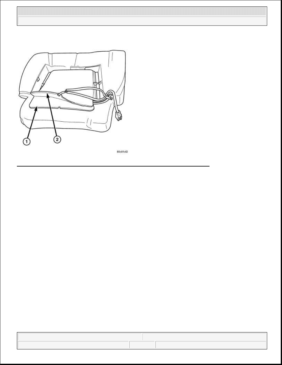
Fig. 13: Peeling Off Adhesive Backing On Back Of Replacement Heating Element
Courtesy of CHRYSLER LLC
1. Peel off the adhesive backing on the back of the replacement heating element (2) and stick directly where
the factory installed heating element (1) was.
CAUTION: During the installation of the replacement heating element, be careful not
to fold or crease the element assembly. Folds or creases will cause
premature failure.
NOTE:
The factory installed heating element should be completely removed from the
system and discarded.
2009 Dodge Grand Caravan SE
2009 ACCESSORIES & EQUIPMENT Heated Seats - Service Information - Grand Caravan, Town & Country
steve
Monday, May 23, 2011 2:11:51 PM
Page 19
© 2006 Mitchell Repair Information Company, LLC.
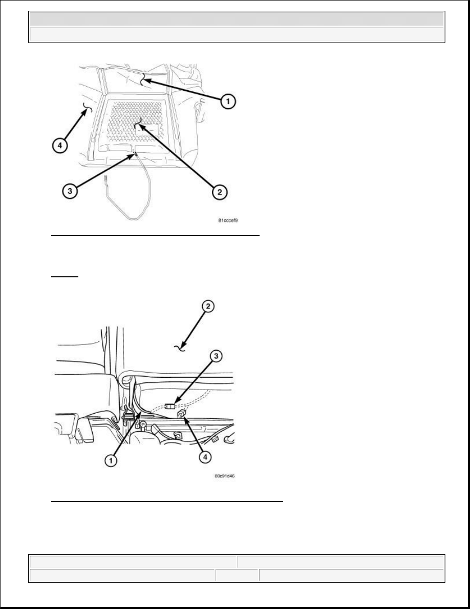
Fig. 14: Seat Back Heated Seat Element Components
Courtesy of CHRYSLER LLC
2. Install the appropriate seat cushion or seat back trim cover (1). Refer to the appropriate procedures in
BODY article .
Fig. 15: Identifying Heating Element Electrical Connectors
Courtesy of CHRYSLER LLC
3. For front row seats and 2nd row Fold 'N Go® seats connect the new heating element electrical connectors
(1, 3 and 4). Passenger seat shown, driver seat similar.
2009 Dodge Grand Caravan SE
2009 ACCESSORIES & EQUIPMENT Heated Seats - Service Information - Grand Caravan, Town & Country
steve
Monday, May 23, 2011 2:11:51 PM
Page 20
© 2006 Mitchell Repair Information Company, LLC.
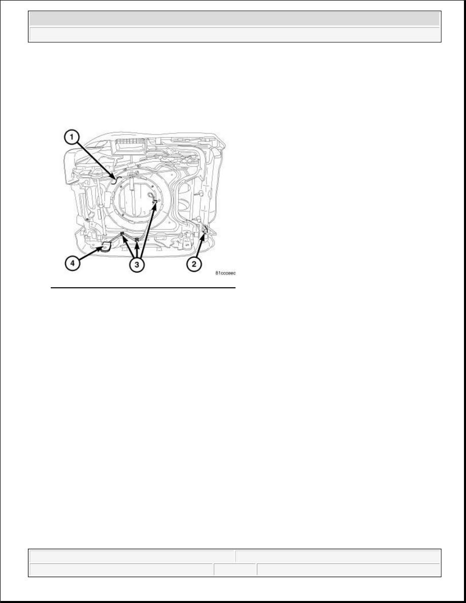
Fig. 16: Heating Element Electrical Connectors
Courtesy of CHRYSLER LLC
4. For 2nd row Swivel 'N Go® seats connect the new heating element electrical connectors (2).
5. Connect the battery negative cable.
6. Verify heated seat system operation.
SWITCH, HEATED SEAT, FRONT
DESCRIPTION
DESCRIPTION
NOTE:
Make certain the seat wire harness is correctly routed through the seat
and seat back. The excess wire between the cushion and back elements
should be securely tucked between the rear of the cushion foam and the
rear carpet flap of the trim cover.
NOTE:
Make certain the seat wire harness is correctly routed through the seat
and seat back. The seat contact should be securely fastened in place (4)
and all wire harness routing clips should be correctly installed (3).
2009 Dodge Grand Caravan SE
2009 ACCESSORIES & EQUIPMENT Heated Seats - Service Information - Grand Caravan, Town & Country
steve
Monday, May 23, 2011 2:11:51 PM
Page 21
© 2006 Mitchell Repair Information Company, LLC.
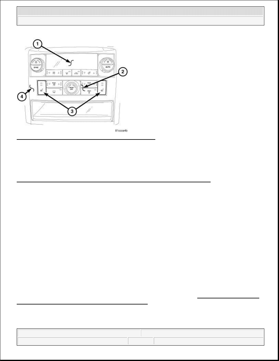
Fig. 17: Identifying Center Stack Rear HVAC Control Unit
Courtesy of CHRYSLER LLC
The two heated seat switches (3) for the front seats are located in the center stack (4) rear HVAC control unit
(2). These two switches allow the driver and front seat passenger to select from two different levels of electrical
seat heating (HI/LO). The front heated seat switches are an integral part of the HVAC control unit. If the
switches are inoperative or damaged in any way the complete HVAC control assembly must be replaced. See
Electrical - Heated/Cooled Systems/Heated Seats/SWITCH, Heated Seat - Removal.
OPERATION
OPERATION
The heated seat switches for the front row seats are located in rear HVAC control assembly. The rear HVAC
control is mounted in the lower portion of the instrument panel center stack. Amber Light Emitting Diodes
(LEDS) in the top portion of each switch indicate the level of heat in use: Two LEDs are illuminated for high,
one for low, and none for off. Pressing the switch once will select high-level heating. Pressing the switch a
second time will select low-level heating. Pressing the switch a third time will shut the heating elements off.
When either of the two momentary, push button-type heated seat switches are depressed a resistance signal is
sent to the ElectroMechanical Instrument Cluster (EMIC) (also known as the Cab Compartment Node/CCN).
The instrument cluster receives this message via the Controller Area Network (CAN) data bus. The instrument
cluster then sends a message via the Local Interconnect Network (LIN) data bus to the heated seat module,
signaling the module to energize the heating element for the selected seat.
The front heated seat switches are an integral part of the HVAC control unit. If the switches are inoperative or
damaged in any way the complete HVAC control assembly must be replaced. See Electrical - Heated/Cooled
Systems/Heated Seats/SWITCH, Heated Seat - Removal.
REMOVAL
REMOVAL
2009 Dodge Grand Caravan SE
2009 ACCESSORIES & EQUIPMENT Heated Seats - Service Information - Grand Caravan, Town & Country
steve
Monday, May 23, 2011 2:11:51 PM
Page 22
© 2006 Mitchell Repair Information Company, LLC.
Automatic Temperature Control (ATC)
Fig. 18: ATC Control
Courtesy of CHRYSLER LLC
1. Disconnect and isolate the negative battery cable.
2. Remove the center bezel (3) from the instrument panel and place it on a workbench (refer to
REMOVAL ).
3. Remove the four screws (1) that secure the A/C-heater control (2) to the instrument panel center bezel and
remove the control.
Manual Temperature Control (MTC)
WARNING:
Disable the airbag system before attempting any steering wheel, steering
column, or instrument panel component diagnosis or service. Disconnect
and isolate the negative battery (ground) cable, then wait two minutes for
the airbag system capacitor to discharge before performing further
diagnosis or service. This is the only sure way to disable the airbag
system. Failure to take the proper precautions may result in accidental
airbag deployment and possible serious or fatal injury.
NOTE:
Take the proper precautions to protect the front face of the instrument panel
center bezel from cosmetic damage during this service procedure.
CAUTION: Be sure to note the color and location of each connector at the back
of the A/C-heater control prior to disconnecting them. Reconnecting
a connector to the wrong receptacle can damage the A/C-heater
control system.
2009 Dodge Grand Caravan SE
2009 ACCESSORIES & EQUIPMENT Heated Seats - Service Information - Grand Caravan, Town & Country
steve
Monday, May 23, 2011 2:11:51 PM
Page 23
© 2006 Mitchell Repair Information Company, LLC.
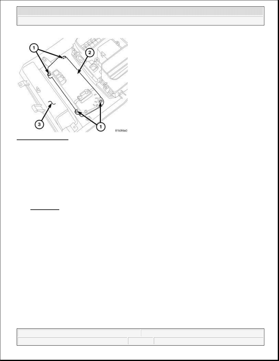
Fig. 19: MTC Control
Courtesy of CHRYSLER LLC
1. Disconnect and isolate the negative battery cable.
2. Remove the center bezel (3) from the instrument panel and place it on a workbench (refer to
REMOVAL ).
3. Remove the four screws (1) that secure the A/C-heater control (2) to the instrument panel center bezel and
remove the control.
INSTALLATION
INSTALLATION
Automatic Temperature Control (ATC)
CAUTION: Be sure to note the color and location of each connector at the back
of the A/C-heater control prior to disconnecting them. Reconnecting
a connector to the wrong receptacle can damage the A/C-heater
control system.
2009 Dodge Grand Caravan SE
2009 ACCESSORIES & EQUIPMENT Heated Seats - Service Information - Grand Caravan, Town & Country
steve
Monday, May 23, 2011 2:11:51 PM
Page 24
© 2006 Mitchell Repair Information Company, LLC.
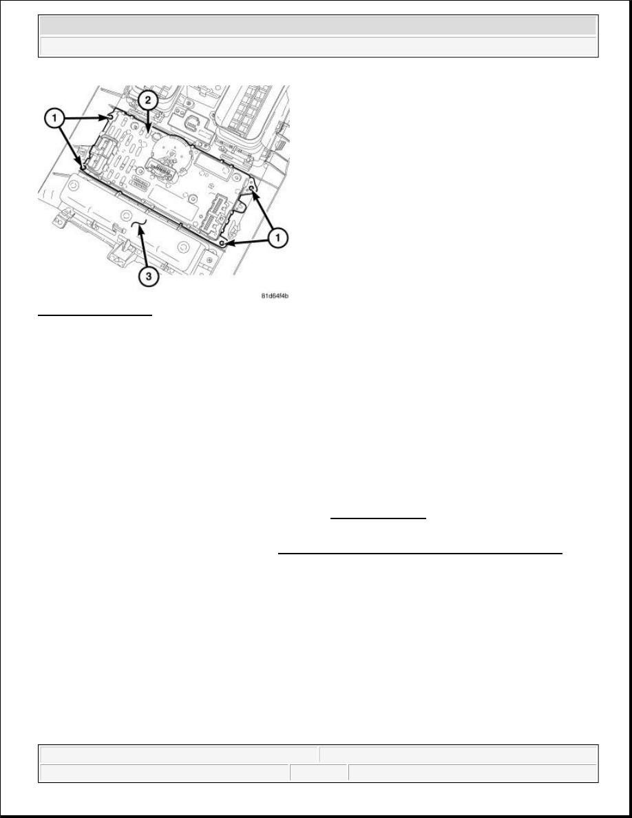
Fig. 20: ATC Control
Courtesy of CHRYSLER LLC
1. Position the A/C-heater control (2) into the instrument panel center bezel (3).
2. Install the screws (1) that secure the A/C-heater control to the center bezel. Tighten the screws to 2 N.m
(17 in. lbs.).
3. Install the instrument panel center bezel (1) (refer to INSTALLATION ).
4. Reconnect the negative battery cable.
5. Calibrate the A/C-heater control. Refer to DTC-Based Diagnostics/HVAC - Standard Procedure .
Manual Temperature Control (MTC)
CAUTION: Each wire connector is individually keyed to its respective receptacle
on the back of the A/C-heater control. Be sure to note the color and
location of each connector when reinstalled to the back of the A/C-
heater control. Do not force any connector onto the A/C-heater
control. Failure to follow this caution can damage the A/C-heater
control system.
2009 Dodge Grand Caravan SE
2009 ACCESSORIES & EQUIPMENT Heated Seats - Service Information - Grand Caravan, Town & Country
steve
Monday, May 23, 2011 2:11:52 PM
Page 25
© 2006 Mitchell Repair Information Company, LLC.
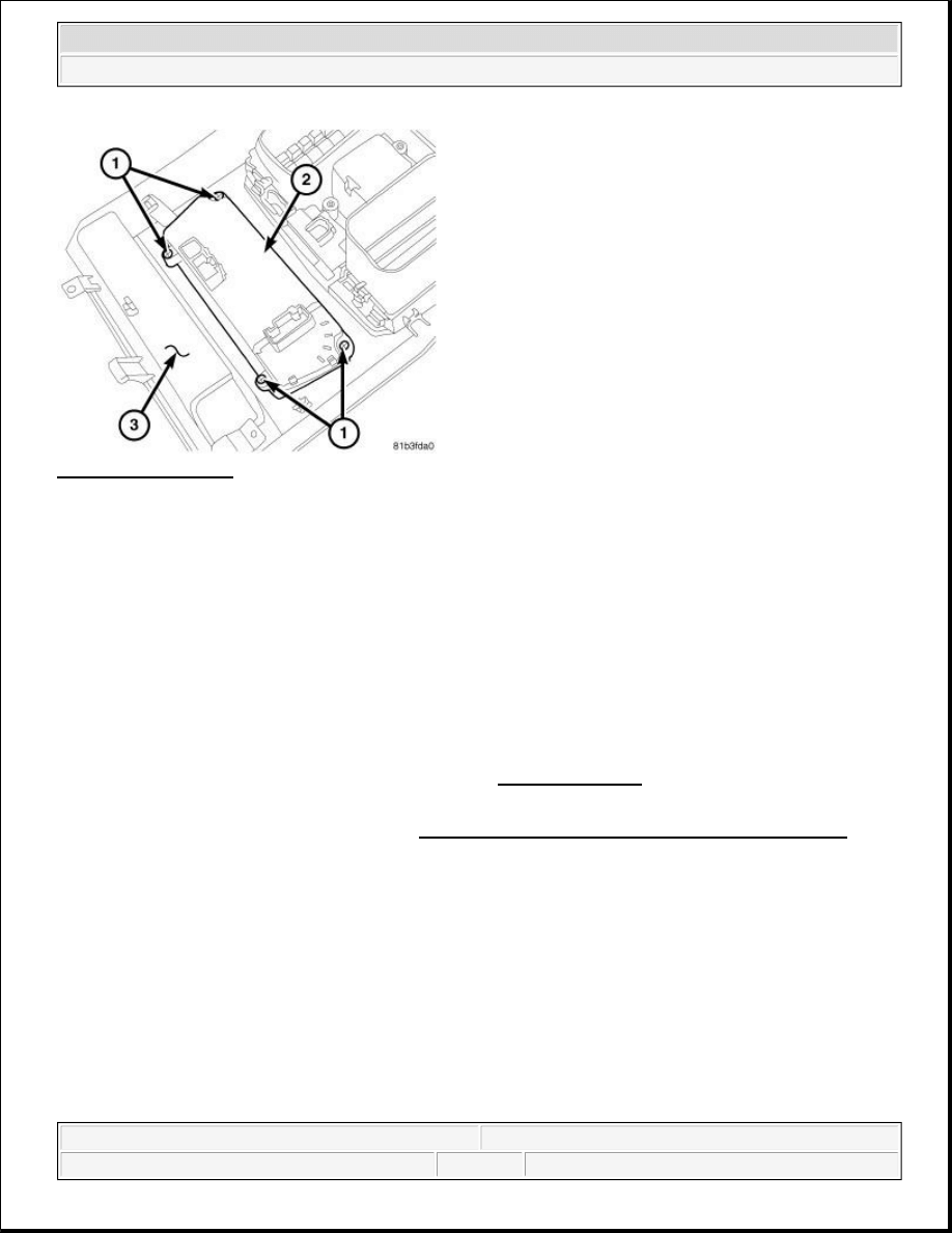
Fig. 21: MTC Control
Courtesy of CHRYSLER LLC
1. Position the A/C-heater control (2) into the instrument panel center bezel (3).
2. Install the screws (1) that secure the A/C-heater control to the center bezel. Tighten the screws to 2 N.m
(17 in. lbs.).
3. Install the instrument panel center bezel (1) (refer to INSTALLATION ).
4. Reconnect the negative battery cable.
5. Calibrate the A/C-heater control. Refer to DTC-Based Diagnostics/HVAC - Standard Procedure .
SWITCH, HEATED SEAT, SECOND ROW
DESCRIPTION
DESCRIPTION
CAUTION: Each wire connector is individually keyed to its respective receptacle
on the back of the A/C-heater control. Be sure to note the color and
location of each connector when reinstalled to the back of the A/C-
heater control. Do not force any connector onto the A/C-heater
control. Failure to follow this caution can damage the A/C-heater
control system.
2009 Dodge Grand Caravan SE
2009 ACCESSORIES & EQUIPMENT Heated Seats - Service Information - Grand Caravan, Town & Country
steve
Monday, May 23, 2011 2:11:52 PM
Page 26
© 2006 Mitchell Repair Information Company, LLC.
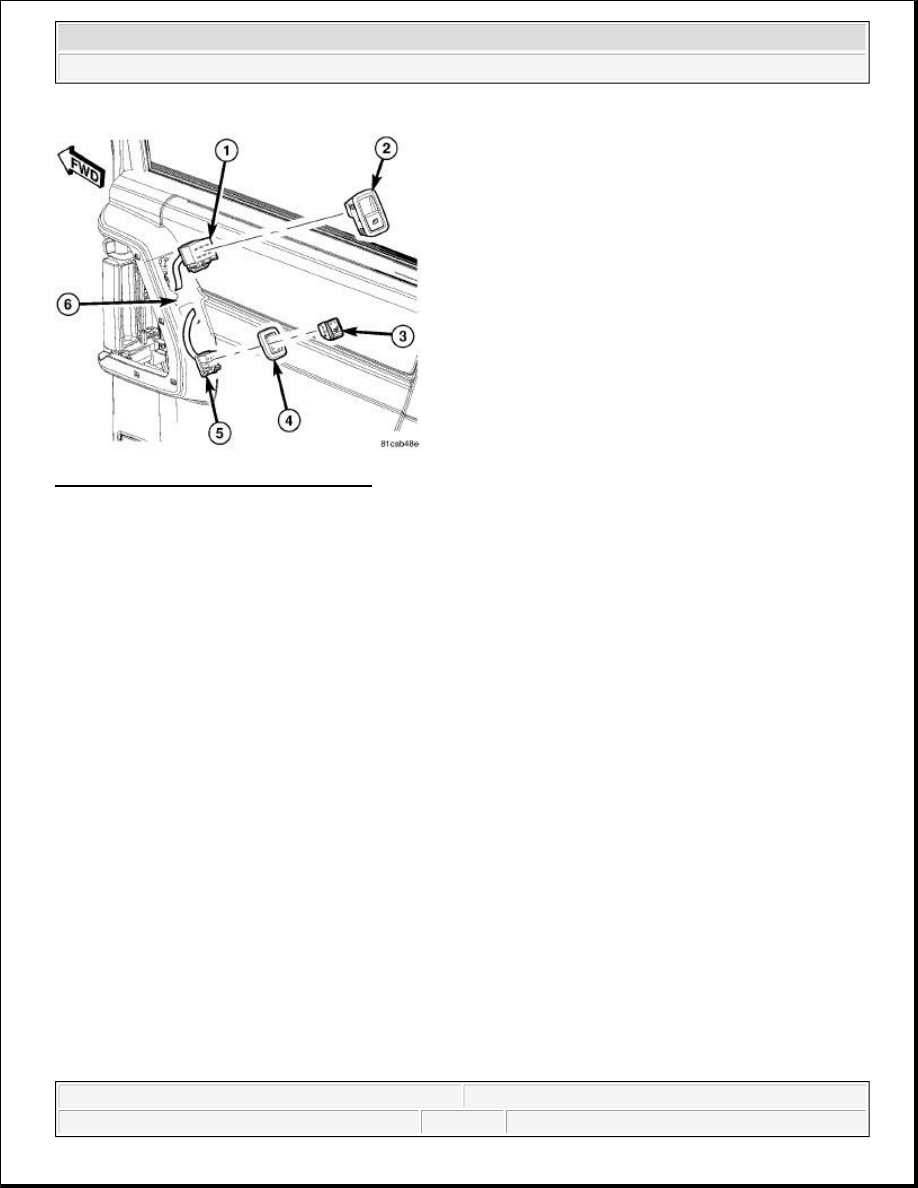
Fig. 22: Identifying Heated Seat Switches
Courtesy of CHRYSLER LLC
The heated seat switches (3) for the 2nd row seats are located in the sliding door trim panels (6) near the door
handles. These switches allow the 2nd row seat passengers to select from two different levels of electrical seat
heating (HI/LO). The two switches are snapped into switch bezels (4) and then snapped into mounting holes in
the sliding door trim panels (6). Amber Light Emitting Diodes (LEDS) in the top portion of each switch indicate
the level of heat in use: Two LEDs are illuminated for high, one for low, and none for off. Pressing the switch
once will select high-level heating. Pressing the switch a second time will select low-level heating. Pressing the
switch a third time will shut the heating elements off.
The two momentary, push button-type heated seat switches provide a hardwired resistance signal to the
applicable Rear Door Module (left or right). The applicable Rear Door Module then sends a message via the
Controller Area Network (CAN) data bus network to the ElectroMechanical Instrument Cluster (EMIC) (also
known as the Cab Compartment Node/CCN). The instrument cluster then sends a message via the Local
Interconnect Network (LIN) data bus to the heated seat module, signaling the module to energize the heating
element for the selected seat. Light Emitting Diodes (LED) in each switch indicate the level of heat in use. The
switch LEDs are controlled by the applicable Rear Door Module.
The two LED indicator lamps and the incandescent bulb in each heated seat switch cannot be repaired. If the
indicator lamps or back lighting bulb are inoperative or damaged, the individual heated seat switch must be
replaced.
OPERATION
OPERATION
The heated seat switches for the 2nd row seats are located in the sliding door trim panels near the door handles.
Amber Light Emitting Diodes (LEDS) in the top portion of each switch indicate the level of heat in use: Two
LEDs are illuminated for high, one for low, and none for off. Pressing the switch once will select high-level
2009 Dodge Grand Caravan SE
2009 ACCESSORIES & EQUIPMENT Heated Seats - Service Information - Grand Caravan, Town & Country
steve
Monday, May 23, 2011 2:11:52 PM
Page 27
© 2006 Mitchell Repair Information Company, LLC.
heating. Pressing the switch a second time will select low-level heating. Pressing the switch a third time will
shut the heating elements off.
When either of the 2nd row heated seat switches are depressed a hardwired resistance signal is sent to the
applicable Rear Door Module (left or right). The applicable Rear Door Module then sends a message via the
Controller Area Network (CAN) data bus network to the ElectroMechanical Instrument Cluster (EMIC) (also
known as the Cab Compartment Node/CCN). The instrument cluster then sends a message via the Local
Interconnect Network (LIN) data bus to the heated seat module, signaling the module to energize the heating
element for the selected seat. Light Emitting Diodes (LED) in each switch indicate the level of heat in use. The
switch LEDs are controlled by the applicable Rear Door Module.
REMOVAL
REMOVAL
Fig. 23: Identifying Heated Seat Switches
Courtesy of CHRYSLER LLC
1. Disconnect and isolate the battery negative cable.
2. Using a trim stick (special tool #C-4755) or equivalent, gently pry the upper edge of the 2nd row heated
seat switch bezel (4) away from the sliding door trim panel (6).
3. Once the upper edge is free from the trim panel, rock the switch and bezel out of the sliding door trim
panel opening.
4. Disconnect the heated seat switch wire harness connector (5).
5. From the back side of the switch bezel (4), gently pry the switch (3) free from the bezel.
INSTALLATION
INSTALLATION
2009 Dodge Grand Caravan SE
2009 ACCESSORIES & EQUIPMENT Heated Seats - Service Information - Grand Caravan, Town & Country
steve
Monday, May 23, 2011 2:11:52 PM
Page 28
© 2006 Mitchell Repair Information Company, LLC.

Fig. 24: Identifying Heated Seat Switches
Courtesy of CHRYSLER LLC
1. Assemble the rear heated switch (3) into the switch bezel (4) by pressing the two together until the
retaining tabs snap securely into place. Make sure that the switch retaining tabs are fully engaged to the
bezel.
2. Connect the wire harness connector (5).
3. Install the switch and bezel assembly into the sliding door trim panel (6). Press the switch into the trim
panel opening until the retaining tabs snap securely into place. Make sure that the switch bezel retaining
tabs are fully engaged to the door trim panel.
4. Connect the battery negative cable.
5. Verify 2nd row heated seat system operation.
NOTE:
Right sliding door shown, left sliding door similar.
2009 Dodge Grand Caravan SE
2009 ACCESSORIES & EQUIPMENT Heated Seats - Service Information - Grand Caravan, Town & Country
steve
Monday, May 23, 2011 2:11:52 PM
Page 29
© 2006 Mitchell Repair Information Company, LLC.
Wyszukiwarka
Podobne podstrony:
Heated Seats Circuit
M39h Seats
72 Seats
FRONT SEATS
Heated mirror repair
M39h Seats
Seats
BMW E38 schematic Heated windshield washer
05a6 E70 Seats
BMW E38 schematic Memory seats
93ZJ Secc 8R Power Seats
72 Seats
20 Restoring Mercedes Seats General
96ZJ 8N ELECTRICALLY HEATED SYSTEMS
heated glass
Elizabeth Lapthorne Montague Vampires 02 Heated Fantasies
Heated Moments
więcej podobnych podstron