POWER SEATS
CONTENTS
page
page
DIAGNOSIS
. . . . . . . . . . . . . . . . . . . . . . . . . . . . . 1
GENERAL
. . . . . . . . . . . . . . . . . . . . . . . . . . . . . . 1
POWER SEAT MOTOR REPLACEMENT
. . . . . . . 3
SEAT REMOVAL/INSTALLATION
. . . . . . . . . . . . . 3
SWITCH TEST
. . . . . . . . . . . . . . . . . . . . . . . . . . . 2
GENERAL
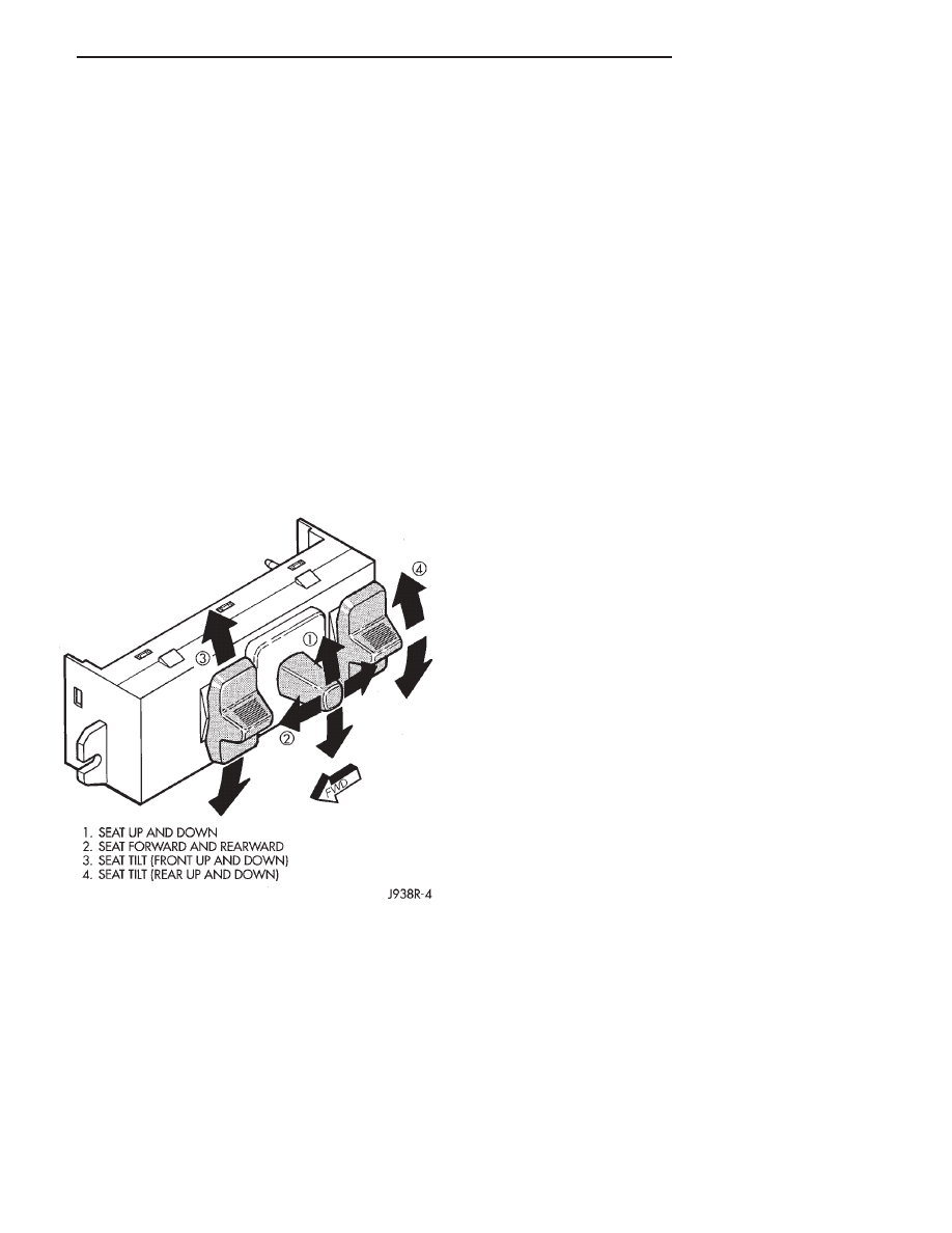
The power seats can be adjusted in six different
directions (Fig. 1). The control switch is located on the
lower outboard side of the seat.
The front lever on the switch raises or lowers (tilts)
the front of the seat; the center lever raises or lowers
the complete seat by moving the switch up or down. It
also moves it forward or rearward by moving the
switch forward or rearward. The rear lever raises or
lowers (tilts) the back of the seat.
There are three reversible motors that operate the
power seats. The front and rear of a seat are operated
by different motors. They can be raised or lowered
independently of each other. When the center seat
switch is pushed to the UP or DOWN position, both
rear and front motors run, moving the entire seat up
or down.
The forward-rearward motor is operated by the cen-
ter position seat switch. When the switch is held in
the FORWARD position, battery voltage is applied
through the switch contacts the forward-rearward
motor. The motor is grounded and the motor runs to
drive the seat forward until the switch is released.
With the switch in the REAR position, the polarity
is reversed and causes the motor to run in the oppo-
site direction and drive the seat backward.
The front motor works in a similar way when the
front height switch is operated.
To raise the entire seat, the center position seat
switch is held in the UP position. This applies battery
voltage to both the front and rear motors. Both mo-
tors run to drive the entire seat up. A similar action
occurs to move the entire seat down.
Each motor contains a self-resetting circuit breaker
to protect it from overload. Consecutive or frequent
resetting must not be allowed to continue. Make nec-
essary repairs.
DIAGNOSIS
Refer to Group 8W-Wiring Diagrams for a complete
circuit diagram.
Before any testing is attempted the battery should be
fully charged and all connections and pins cleaned and
tightened to ensure proper continuity and grounds.
With the dome light on, apply switch in direction of
the failure. If the dome light dims, the seat may be
jamming. Check for binding. If the dome light does not
dim, then proceed with the following electrical tests.
SEAT MOTOR ASSEMBLY
• Position Seat Switch to move all three Seat Motors.
The seat should move in all directions. If not, go to No
Seat Motors Operate. If one or more motors operate,
refer to switch testing.
Test Seat Switch. If ok, replace defective motor.
NO SEAT MOTORS OPERATE
Power Seats circuit breaker #25 installed.
• Probe Power Seats 30 amp circuit breaker, #25 on
fuse panel. If battery voltage is present, replace circuit
breaker.
• Remove switch mounting screws and measure volt-
age at Red wire at switch. Meter should read battery
voltage. If not, repair open to power.
• Measure resistance at black wire at switch. Meter
should read zero ohms. If OK, replace switch. If not,
repair open to ground.
Fig. 1 Power Seat Switch
Z
POWER SEATS
8R - 1
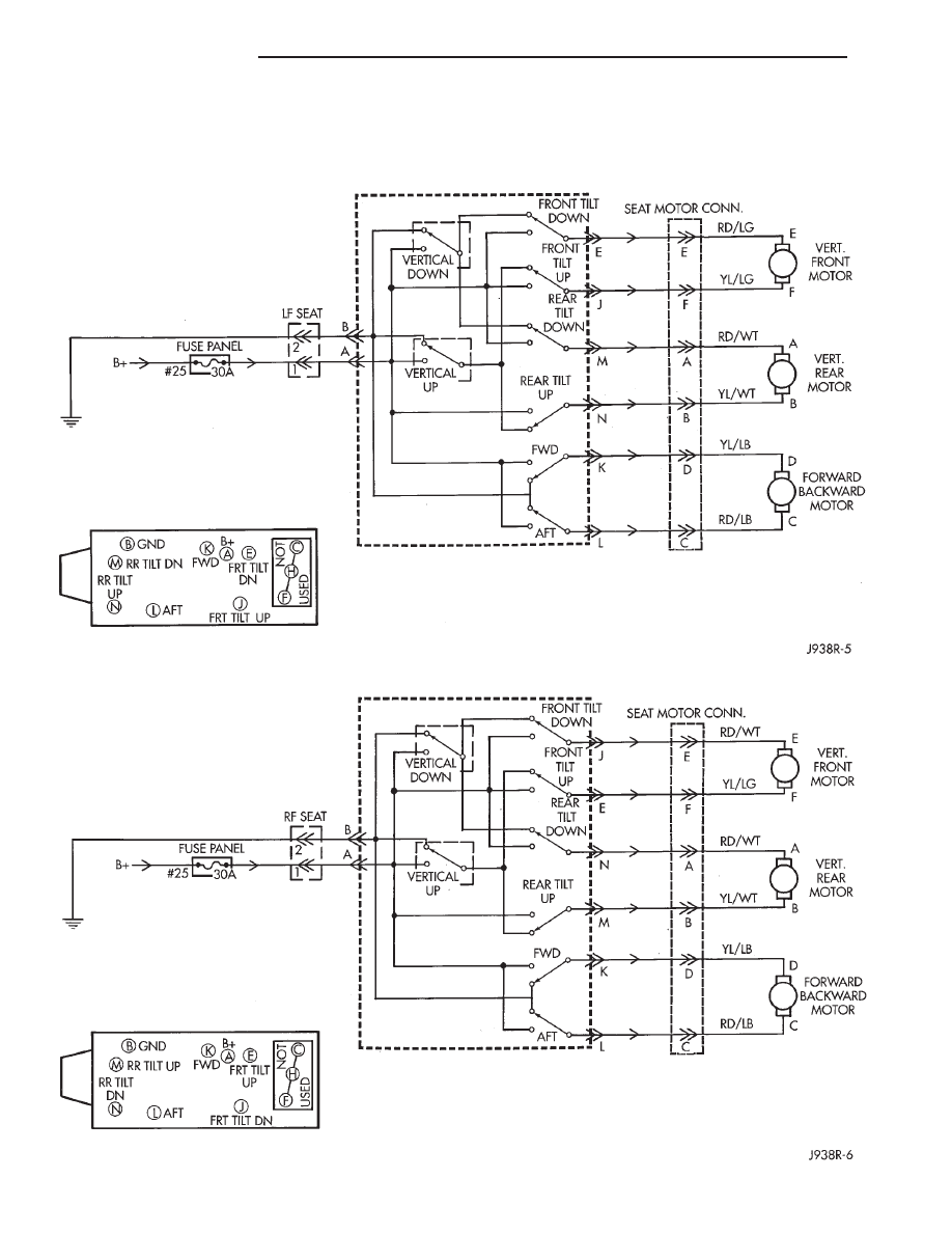
SWITCH TEST
To check the switch, remove the switch from its
mounting position. Using an ohmmeter, and referring to
the schematic, determine if continuity is correct. If
there is not continuity at any one of the switch posi-
tions, replace the switch.
DRIVER’S POWER SEAT
PASSENGER’S POWER SEAT
8R - 2
POWER SEATS
Z
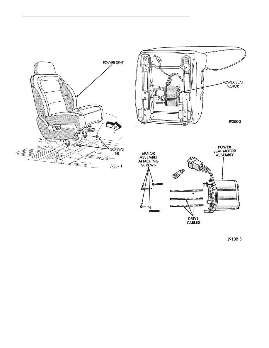
SEAT REMOVAL/INSTALLATION
REMOVAL
(1) Remove 2 screws and the rear track covers.
(2) Remove 4 screws holding seat to floor pan (Fig.
2). Move adjuster as required for access.
(3) Disconnect wiring harness power lead at carpet.
(4) Remove seat assembly from vehicle.
INSTALLATION
(1) Position seat assembly in vehicle.
(2) Connect wiring harness.
(3) Install and tighten mounting bolts to 20 N
Im
(15 ft. lbs.).
(4) Install rear track covers.
(5) Check seat operation.
POWER SEAT MOTOR REPLACEMENT
(1) Remove
seat
as
described
in
Seat
Removal/Installation.
CAUTION: Take care to avoid excessive bending of
the three drive cables when removing/installing the
motor assembly.
(2) Remove screws attaching motor assembly to
seat frame and remove motor assembly and mounting
spacers (Figs. 3 and 4).
(3) To install the power seat motor, reverse the
removal procedures. Tighten seat mounting bolts to
20 N
Im (15 ft. lbs.).
Fig. 2 Power Seat Removal—Right Side Shown
Fig. 3 Power Seat Motor Installation—Right Side
Shown
Fig. 4 Power Seat Motor Assembly
Z
POWER SEATS
8R - 3

Document Outline
Wyszukiwarka
Podobne podstrony:
93ZJ Secc 8T Power Mirrors
93ZJ Secc 8S Power Windows
93ZJ Secc 8P Power Door Locks
93ZJ Secc 11 Exhaust System and Intake Manifold
93ZJ Secc 8J Turn Signals and Hazard Warning Flashes
93ZJ Secc 8F Audio Systems
93ZJ Secc 16 Propeller Shafts
93ZJ Secc 6 Clutch
93ZJ Secc 8L Lamps
93ZJ Secc 8B Battery Starter Motor Generator Service
93ZJ Secc 8A Electrical Systems
93ZJ Secc 8M Restraint Systems
93ZJ Secc 22 Wheels and Tires
96ZJ 8R POWER SEAT SYSTEMS
93ZJ Secc 25 Emission Control Systems
93ZJ Secc 0 Lubrication and Maintenance
93ZJ Secc 8G Horns
power seats front
93ZJ Secc 8Q Vehicle Theft Security System
więcej podobnych podstron