BATTERY/STARTER MOTOR/GENERATOR SERVICE
CONTENTS
page
page
BATTERY SERVICE PROCEDURES
. . . . . . . . . . . 1
ENGINE STARTER MOTOR SERVICE
PROCEDURES
. . . . . . . . . . . . . . . . . . . . . . . . . 4
GENERATOR SERVICE PROCEDURES
. . . . . . . . 6
SPECIFICATIONS
. . . . . . . . . . . . . . . . . . . . . . . . 9
BATTERY SERVICE PROCEDURES
GENERAL INFORMATION
This section covers Battery rermoval and installa-
tion procedures only. For diagnostic procedures. refer
to Group 8A - Battery/Starting/Charging Systems Di-
agnostics.
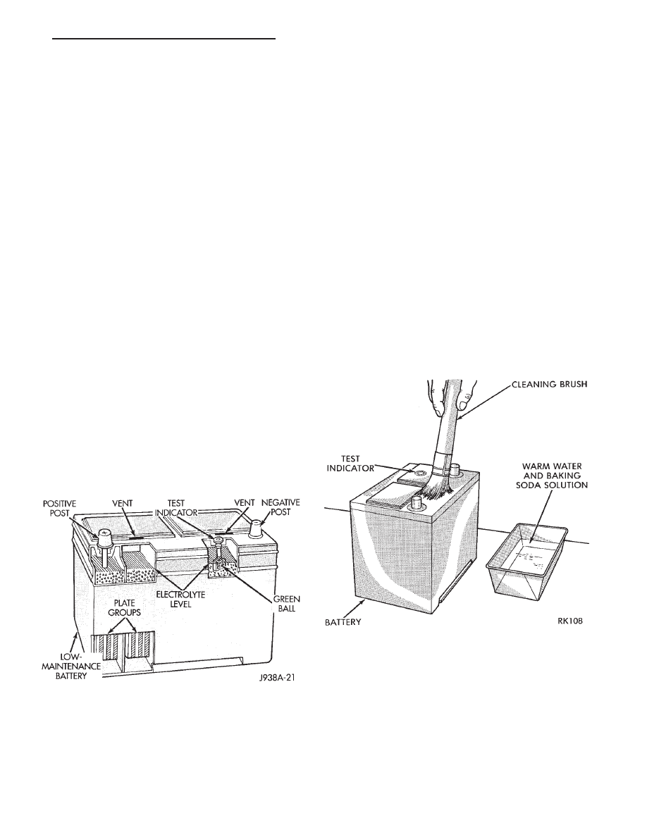
The Low Maintenance Battery (Fig. 1) has remov-
able battery cell caps. Water can be added to this
battery. The battery is not sealed and also has small
vent holes in the top. The chemical composition inside
of the battery produces an extremely small amount of
gases at normal charging voltages. The battery is
equipped with a test indicator (Fig. 1) that displays a
colored ball to indicate battery state-of-charge.
Green Indicator = Full charge
Black Indicator = Discharged
Yellow Indicator = Battery replacement required
BATTERY MAINTENANCE
(1) Inspect the cable terminal for corrosion and
damage. Remove the corrosion using a wire brush, or
post
and
terminal
cleaner,
and
a
sodium
bicarbonate/water solution. Replace cables that have
damaged or deformed terminals.
Be sure vents are installed when washing bat-
tery to prevent solution from entering battery.
(2) Clean the outside of the battery case if the
original battery is to be installed. Clean the top cover
with diluted ammonia or a sodium bicarbonate/water
solution to remove the acid film (Fig. 2). Flush with
clean water. Ensure that the cleaning solution does
not enter the cells.
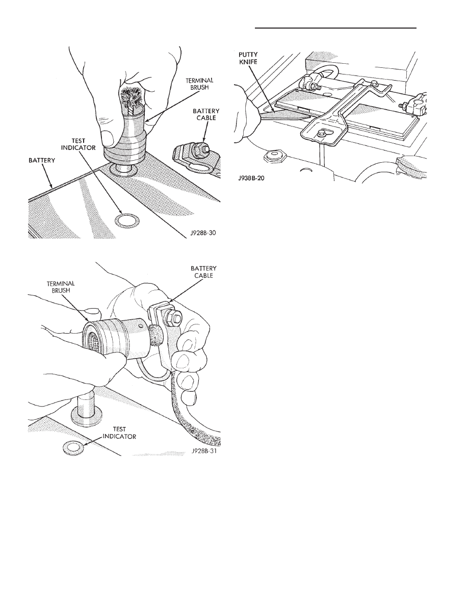
(3) Remove corrosion from the terminals with a
wire brush or post and terminal cleaner (Figs. 3 and
4). Inspect the case for cracks or other damage that
would result in leakage of electrolyte.
Check electrolyte level in the battery. Use a putty
knife or other suitable wide tool to pry filler caps off
low maintenance battery (Fig. 5). Do not use a screw-
driver. Add distilled water to each cell until the liquid
reaches the bottom of the vent well. DO NOT OVER-
FILL.
Fig. 1 Low Maintenance Battery
Fig. 2 Cleaning Battery
Z
BATTERY/STARTER MOTOR/GENERATOR SERVICE
8B - 1
Operate the engine immediately after adding water
(particularly in cold weather) to assure proper mixing
of the water and acid.
BATTERY REPLACEMENT
REMOVAL
(1) Make sure ignition switch is in OFF position
and all electrical accessories are OFF.
(2) Loosen the cable terminal clamps.
(3) If necessary, use a puller to remove the cable
terminal clamps, and remove the negative cable ter-
minal clamp first.
WARNING: WEAR A SUITABLE PAIR OF RUBBER
GLOVES (NOT THE HOUSEHOLD TYPE) WHEN RE-
MOVING A BATTERY BY HAND. IF THE BATTERY IS
CRACKED OR LEAKING THE ELECTROLYTE CAN
BURN THE SKIN.
(4) Remove battery holddowns and remove battery
from vehicle (Fig. 6).
(5) Inspect the battery tray and holddowns for cor-
rosion. Remove corrosion using a wire brush and a
sodium bicarbonate/water solution. Paint any exposed
bare metal. Replace damaged components (Fig. 6).
If the battery tray needs to be replaced, dis-
connect the hoses from the vacuum reservoir to
remove the tray. Remove the vacuum reservoir
from the bottom to the battery tray.
INSTALLATION
(1) Refer to Specifications to determine if the bat-
tery has the correct classification and rating for the
vehicle.
(2) Use a hydrometer to test the battery electrolyte.
Charge the battery if necessary.
(3) Position the battery in the tray. Ensure that the
positive and negative terminals (posts) are correctly
located. The cables must reach their respective termi-
nals (posts) without stretching (Fig. 7).
(4) Ensure that the tang at the battery base is
positioned in the tray properly before tightening the
holddown.
CAUTION: It is imperative that the cables are con-
nected
to
the
battery
positive-to-positive
and
negative-to-negative. Reverse polarity will damage
the generator diodes and radio(s).
Fig. 3 Cleaning Battery Post
Fig. 4 Cleaning Battery Terminals
Fig. 5 Removing Filler Cap
8B - 2
BATTERY/STARTER MOTOR/GENERATOR SERVICE
Z
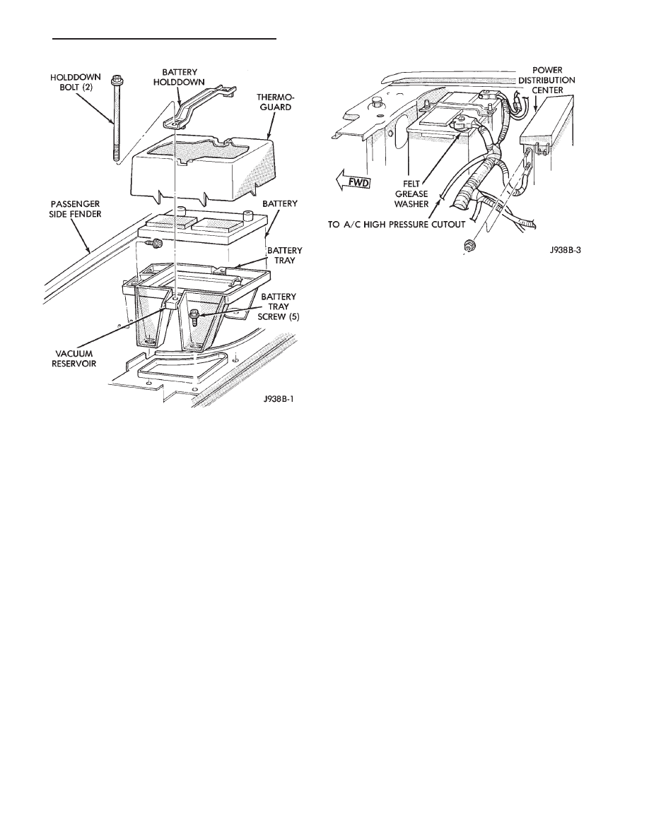
(5) Place the felt washer on the positive battery
terminal.
(6) Connect the positive cable first. Then connect
the negative cable. Tighten both cable terminal bolts
to 8.5 N
Im (75 in. lbs.).
(7) Apply a thin coating of petroleum jelly or chas-
sis grease to the cable terminals and the battery
posts.
(8) Inspect the negative cable connections on the
engine and the vehicle body for condition, security
and electrical continuity.
Fig. 6 Battery Tray and Holddown
Fig. 7 Battery Cable Connections
Z
BATTERY/STARTER MOTOR/GENERATOR SERVICE
8B - 3
ENGINE STARTER MOTOR SERVICE PROCEDURES
GENERAL INFORMATION
This section will cover the Starting System compo-
nent service procedures only. For diagnostic proce-
dures, refer to Group 8A - Battery/Starting/Charging
Systems Diagnostics.
The starter system circuits consist of:
• a battery
• starter motor and solenoid
• starter relay
• ignition switch
• park/neutral positon switch (automatic transmis-
sion)
• connecting wires and battery cables.
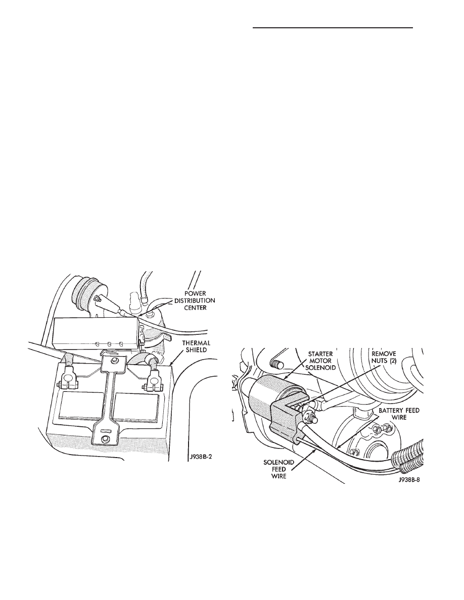
STARTER RELAY REPLACEMENT
The starter relay is located in the Power Distribu-
tion Center (Fig. 1). Refer to the underside of the
Power Distribution Cover for relay location.
(1) Disconnect negative cable from battery.
(2) Replace the relay.
(3) Connect battery cable.
(4) Test relay operation.
STARTER MOTOR GENERAL INFORMATION—4.0L
The Mitsubishi starter motor is a light-weight unit
featuring a planetary gear drive and permanent mag-
nets for current induction.
The planetary gear drive is splined to both the
armature shaft and overrunning clutch. Starter
torque is transmitted to the overrunning clutch pin-
ion through the planetary gears which provide higher
rotational speeds.
The starter magnetic field is produced by six per-
manent magnets. The magnets are mounted in the
armature frame and positioned according to polarity.
They are permanently attached to the frame and are
not removable.
The starter motor is activated by a solenoid
mounted on the overrunning clutch housing.
This unit is highly sensitive to hammering, shocks,
and external pressure.
CAUTION:
The
starter
motor
MUST
NOT
BE
CLAMPED in a vise by the stator frame. Doing so
may damage the magnets. It may be clamped by the
mounting flange ONLY.
CAUTION: Do not connect the starter motor incor-
rectly when electrical tests are being performed. The
magnets may be damaged and rendered unservice-
able.
• Ensure cleanliness when performing repairs.
• Metal chips are attracted by the magnets and may
not be completely removed from the stator frame.
Chips in the ring gear can lead to failure of the
starter.
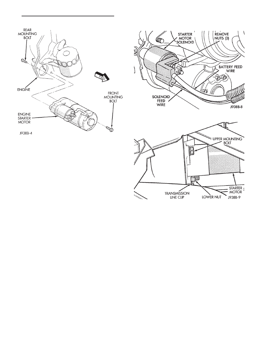
STARTER MOTOR REMOVAL/INSTALLATION—4.0L
(1) Disconnect negative cable from battery.
(2) Raise and support vehicle.
(3) Disconnect the battery wire and solenoid feed
wire connector (Fig. 2).
(4) Remove starter front mounting bolt (Fig. 3).
(5) Remove starter rear mounting bolt and remove
starter.
(6) To install the starter motor, reverse the removal
procedures and torque the mounting hardware as
follows:
• Tighten starter mounting bolts to 45 NIm (33 ft. lbs.).
Fig. 1 Power Distribution Center
Fig. 2 Solenoid Harness Removal
8B - 4
BATTERY/STARTER MOTOR/GENERATOR SERVICE
Z
• Tighten the terminal adapter solenoid nut to 6
N
Im (55 in. lbs.).
• Tighten the terminal adapter battery cable nut to
10 N
Im (90 in. lbs.).
(7) Remove vehicle support and lower vehicle.
(8) Install negative cable to battery.
STARTER MOTOR GENERAL INFORMATION—5.2L
A Nippondenso reduction gear field coil starter mo-
tor is used on the 5.2L engine. This starter motor
features compact design and is lightweight as com-
pared with those having the same output. Structure
is different from that of direct drive and permanent
magnet type, but electrical wiring is common for all
engines. The reduction gear sets and solenoid shift
devices are enclosed in an aluminum die cast housing
which is part of starter assembly.
STARTER MOTOR REMOVAL/INSTALLATION—5.2L
(1) Disconnect negative cable from battery.
(2) Raise and support vehicle.
(3) Disconnect the battery wire and solenoid feed
wire connector (Fig. 4).
(4) Remove lower mounting nut (Fig. 5).
(5) Remove transmission line clip from stud.
(6) Remove upper mounting bolt.
(7) Pull starter forward and remove from vehicle.
(8) To install the starter motor, reverse the removal
procedures and torque the mounting hardware as
follows:
• Tighten starter upper mounting bolt and stud nut
to 68 N
Im (50 ft. lbs.).
• Tighten the terminal adapter solenoid nut to 6
N
Im (55 in. lbs.).
• Tighten the terminal adapter battery cable nut to
10 N
Im (90 in. lbs.).
(9) Remove vehicle support and lower vehicle.
(10) Install negative cable to battery.
PARK/NEUTRAL POSITION SWITCH
Refer to Group 21 for diagnostic, removal and in-
stallation procedures.
Check linkage adjustment before replacing
the switch.
Fig. 3 Starter Motor Removal/Installation—Typical
Fig. 4 Solenoid Harness Removal—Typical
Fig. 5 Starter Motor Removal/Installation (Typical)
Z
BATTERY/STARTER MOTOR/GENERATOR SERVICE
8B - 5
GENERATOR SERVICE PROCEDURES
GENERAL
The generator is belt-driven by the engine. This
section will cover generator removal and installation.
The generator is not serviceable. Information covering
on-vehicle testing can be found in Group 8A -
Battery/Starting/Charging Systems Diagnostics.
GENERATOR REMOVAL AND INSTALLATION—4.0L
WARNING: FAILURE TO DISCONNECT THE NEGA-
TIVE CABLE FROM THE BATTERY BEFORE DIS-
CONNECTING THE RED (OUTPUT) WIRE CONNEC-
TOR FROM THE GENERATOR CAN RESULT IN
INJURY.
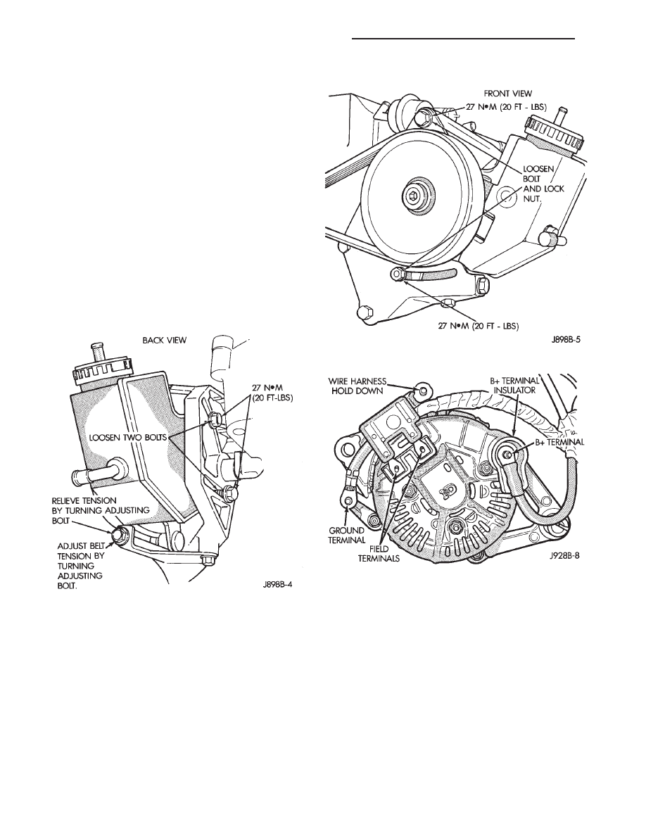
Belt tension is adjusted at the power steering
pump.
(1) Disconnect negative cable from battery.
(2) Loosen rear mounting bolts (Fig. 1).
(3) Loosen power steering pump pivot bolt and lock
nut (Fig. 2).
(4) Loosen adjusting bolt to remove belt.
(5) Raise and support vehicle.
(6) Remove B+ terminal nut, 2 field terminal nuts,
ground and harness hold down nuts (Fig. 3). Remove
wire connector assembly.
(7) Remove 2 generator mounting bolts and remove
generator from vehicle.
(8) Install generator with two mounting bolts.
Torque bolts to 55 N
Im (41 ft. lbs.).
(9) Attach generator wires.
CAUTION: Never force a belt over a pulley rim using
a screwdriver as the synthetic fiber may be dam-
aged.
CAUTION: When installing a serpentine accessory
drive belt, the belt MUST be routed correctly. The
engine may overheat because the water pump will
be rotating in the wrong direction if the belt is
installed incorrectly. Refer to the appropriate acces-
sory drive belt schematic for the correct belt routing
(Group 7).
(10) Place serpentine belt over pulley.
(11) The 2 rear mounting bolts and the power steer-
ing pump pivot bolt should be finger tight.
Fig. 1 P.S Pump Rear Mounting Bolts
Fig. 2 P.S Pump Front Mounting Bolts
Fig. 3 Remove or Install Connector Assembly
8B - 6
BATTERY/STARTER MOTOR/GENERATOR SERVICE
Z
(12) Turn adjusting bolt until the belt has the cor-
rect tension as given in Specifications.
(13) Tighten rear mounting bolts, pivot bolt, and
lock nut to 27 N
Im (20 ft. lbs.) torque.
(14) Remove support and lower vehicle.
(15) Attach negative cable to the battery.
GENERATOR REMOVAL AND INSTALLATION—5.2L
ENGINE
WARNING: FAILURE TO DISCONNECT THE NEGA-
TIVE CABLE FROM THE BATTERY BEFORE DIS-
CONNECTING THE RED (OUTPUT) WIRE CONNEC-
TOR FROM THE GENERATOR CAN RESULT IN
INJURY.
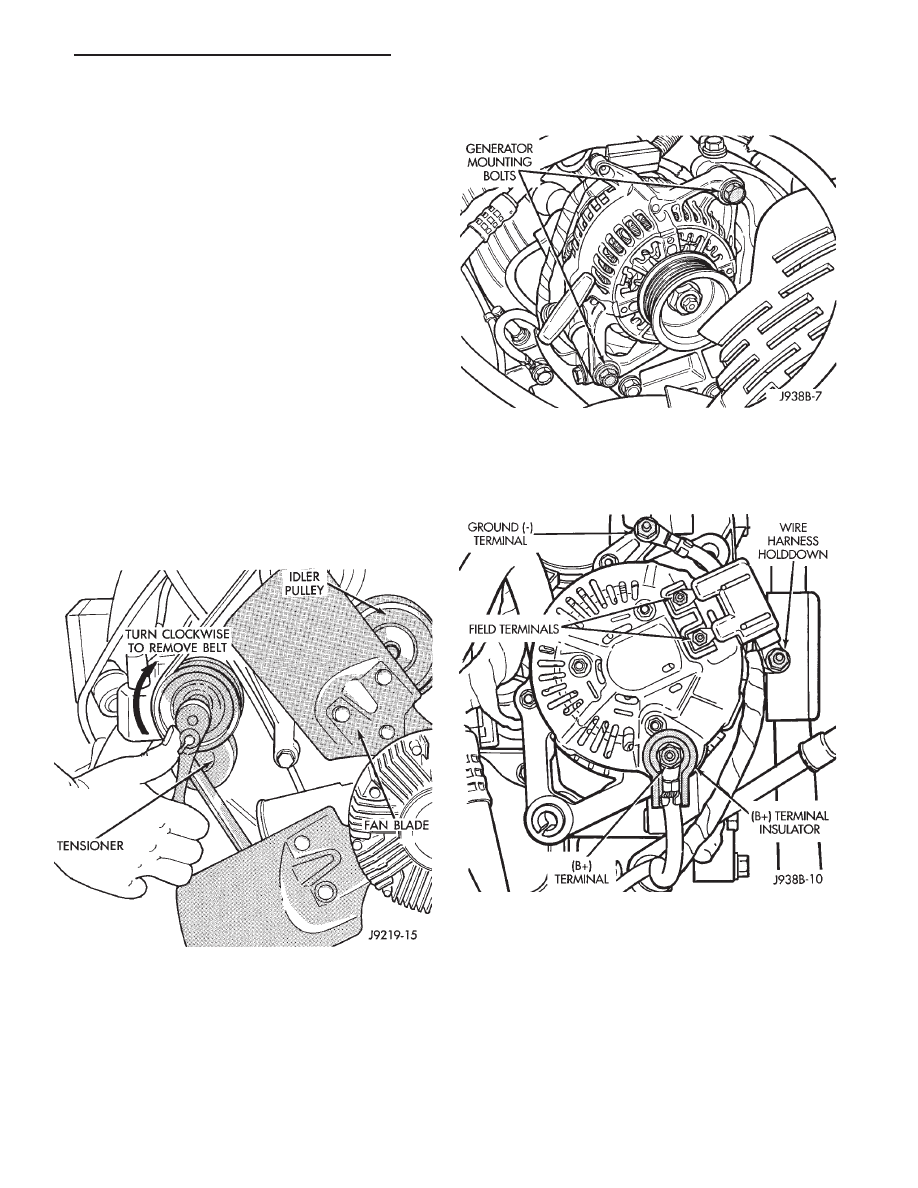
REMOVAL
Drive belts on the 5.2L engine are equipped with a
spring loaded automatic belt tensioner (Fig. 4). This
belt tensioner is used on all belt configurations. For
more information, refer to Group 7 - Cooling, Auto-
matic Belt Tensioner—5.2L Engines.
(1) Disconnect negative cable from battery.
(2) Attach a socket/wrench to the pulley mounting
bolt of the automatic tensioner (Fig. 4).
(3) Rotate the tensioner assembly clockwise (as
viewed from front) until tension has been relieved
from belt.
(4) Remove belt from vehicle.
(5) Remove lower generator mounting bolt and nut
(Fig. 5).
(6) Remove upper generator mounting bolt and re-
move generator from bracket.
(7) Remove the B+ terminal nut, 2 field terminal
nuts, ground, and harness hold down nuts (Fig. 6).
Remove wire connectors.
INSTALLATION
(1) Install generator. Tighten both bolts to 41 N
Im
(30 ft. lbs.).
CAUTION: When installing the serpentine accessory
drive belt, the belt MUST be routed correctly. If not,
the engine may overheat due to the water pump
rotating in the wrong direction. Refer to (Fig. 7) for
correct 5.2L engine belt routing. The correct belt
with the correct length must be used
Fig. 4 Automatic Belt Tensioner—Belt Removal/
Installation
Fig. 5 Generator Mounting Bolts
Fig. 6 Remove or Install Wire Connector Assembly
Z
BATTERY/STARTER MOTOR/GENERATOR SERVICE
8B - 7
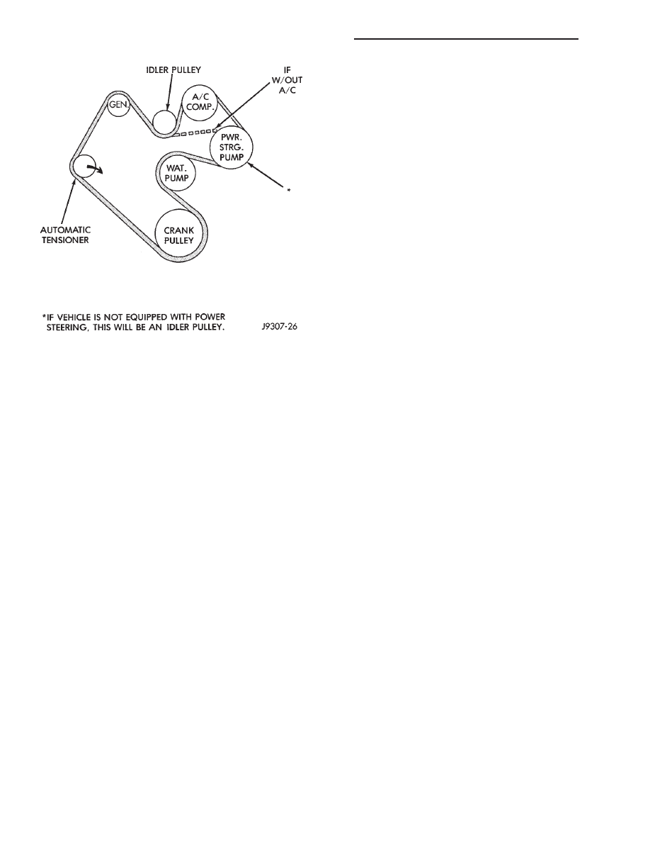
(2) Position the drive belt over all pulleys except
the idler pulley. This pulley is located between the
generator and A/C compressor.
(3) Attach a socket/wrench to the pulley mounting
bolt of the automatic tensioner (Fig. 4).
(4) Rotate the socket/wrench clockwise. Place the
belt over the idler pulley. Let tensioner rotate back
into place. Remove wrench. Be sure belt is properly
seated on all pulleys.
(5) Check belt indexing marks. Refer to Group 7 -
Cooling, Automatic Belt Tensioner—5.2L Engine for
more belt information.
Fig. 7 Belt Routing—5.2L Engine
8B - 8
BATTERY/STARTER MOTOR/GENERATOR SERVICE
Z
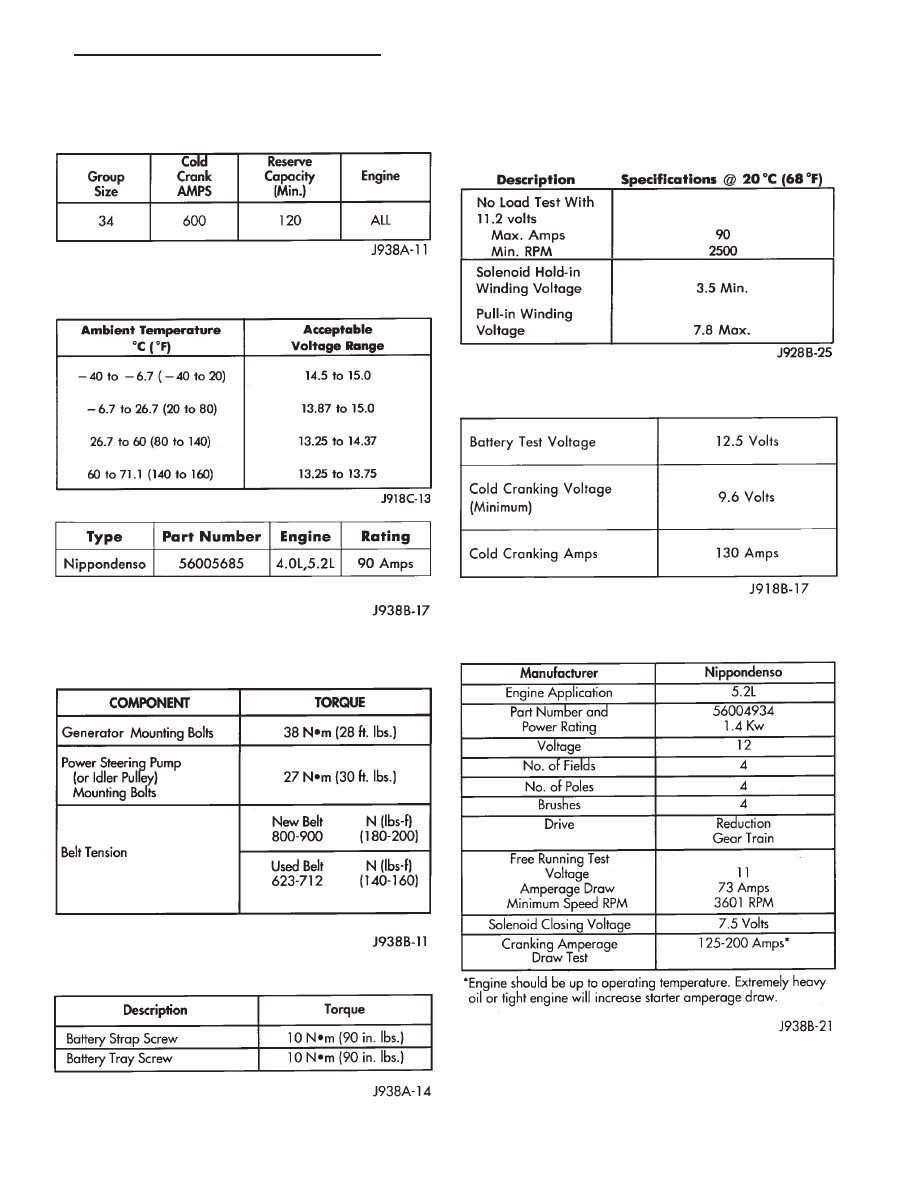
SPECIFICATIONS
4.0L ENGINE
5.2L ENGINE
BATTERY CLASSIFICATIONS AND RATINGS
GENERATOR OUTPUT VOLTAGE
SPECIFICATIONS
TORQUE SPECIFICATIONS
TORQUE SPECIFICATIONS
ENGINE STARTER MOTOR AND SOLENOID
TESTING SPECIFICATIONS
ENGINE STARTER MOTOR COLD CRANKING
SPECIFICATIONS
REDUCTION GEAR STARTER
Z
BATTERY/STARTER MOTOR/GENERATOR SERVICE
8B - 9

Document Outline
- BATTERY/ STARTER MOTOR/ GENERATOR SERVICE
Wyszukiwarka
Podobne podstrony:
93ZJ Secc 11 Exhaust System and Intake Manifold
93ZJ Secc 8J Turn Signals and Hazard Warning Flashes
93ZJ Secc 8F Audio Systems
93ZJ Secc 8R Power Seats
93ZJ Secc 16 Propeller Shafts
93ZJ Secc 6 Clutch
93ZJ Secc 8L Lamps
93ZJ Secc 8A Electrical Systems
93ZJ Secc 8M Restraint Systems
93ZJ Secc 22 Wheels and Tires
93ZJ Secc 25 Emission Control Systems
93ZJ Secc 0 Lubrication and Maintenance
93ZJ Secc 8G Horns
93ZJ Secc 8Q Vehicle Theft Security System
93ZJ Secc 8T Power Mirrors
ac system general servicing
93ZJ Secc 8K Windshield Wiper and Washer Systems
93ZJ Secc 8C Overhead Console
93ZJ Secc 8U Chime Buzzer Warning Systems
więcej podobnych podstron