POWER MIRRORS
CONTENTS
page
page
AUTOMATIC DAY/NIGHT REAR VIEW MIRROR
. 6
POWER SIDE MIRRORS . . . . . . . . . . . . . . . . . . . 1
POWER SIDE MIRRORS
INDEX
page
page
General Information
. . . . . . . . . . . . . . . . . . . . . . . . 1
Heated Mirror
. . . . . . . . . . . . . . . . . . . . . . . . . . . . 1
Mirror Assembly Replacement
. . . . . . . . . . . . . . . . 5
Mirror Switch Replacement . . . . . . . . . . . . . . . . . . . 2
Mirror Switch Test Procedure
. . . . . . . . . . . . . . . . . 2
Mirror Test Procedure . . . . . . . . . . . . . . . . . . . . . . . 1
GENERAL INFORMATION
For information concerning wiring or connectors,
refer to Group 8W - Wiring Diagrams.
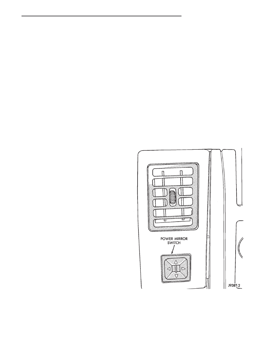
The mirror control switch uses a paddle which is
moved Left or Right for mirror selection and 4 but-
tons for mirror movement direction (Fig. 1).
Each mirror has two reversible motors: one to ad-
just the mirror view up and down, the other to adjust
the mirror view right and left. The driver operates
the switch that controls the polarity of the voltage to
the motors. The mirror select switch directs these
control voltages to either the RH or LH mirror.
The mirror select switch must be set to L or R to
direct current flow.
HEATED MIRROR
The heated mirror is controlled by the rear window
defogger switch. The mirror heater is on only when
the rear window defogger switch is on.
Refer to Group 8N - Rear Window Defogger.
MIRROR TEST PROCEDURE
CAUTION: The wiring harness to the door switches
is just long enough to allow installation. If trim panel
is pulled off by hand the switch may be pulled apart.
Use a door clip tool to prevent damaging the
switches.
(1) Remove the door trim panel with a wide flat
blade tool (Fig. 2).
To aid in removal of the trim panel, start at
the bottom of the panel.
(2) Unplug door wiring harness connector.
(3) Connect a jumper wire to a 12 volt source.
(4) Connect another jumper wire to a good body
ground.
(5) Refer to Mirror Motor Test for appropriate pin
numbers (Fig. 3).
Fig. 1 Power Mirror Switch
Z
POWER MIRRORS
8T - 1
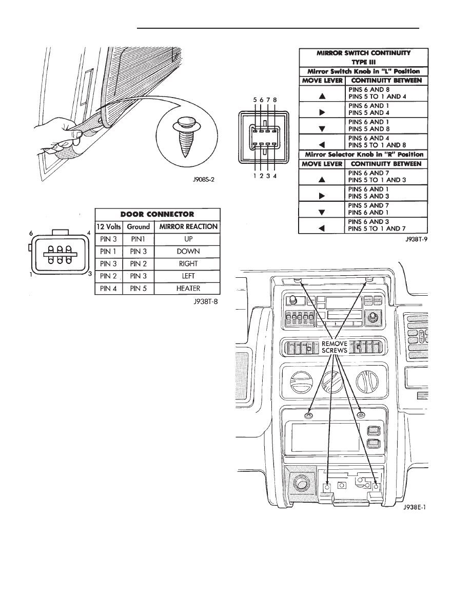
MIRROR SWITCH TEST PROCEDURE
(1) Remove power mirror switch from mounting po-
sition.
(2) Unplug wiring harness connector.
(3) Using an ohmmeter, test for continuity between
the terminals of the switch as shown in the Mirror
Switch Test (Fig. 4).
MIRROR SWITCH REPLACEMENT
(1) Disconnect negative cable from the battery.
(2) Remove ash tray.
(3) Remove 6 screws holding center cluster bezel
(Fig. 5).
(4) Remove center bezel.
(5) Remove 2 screws holding dash pad located be-
hind top of center bezel.
(6) Gently pry defroster grille out of dash pad.
(7) Unplug sensors (if equipped) and set defroster
grille aside.
Fig. 2 Trim Panel Removal
Fig. 3 Mirror Motor Test
Fig. 4 Mirror Switch Test
Fig. 5 Remove Center Bezel Screws
8T - 2
POWER MIRRORS
Z
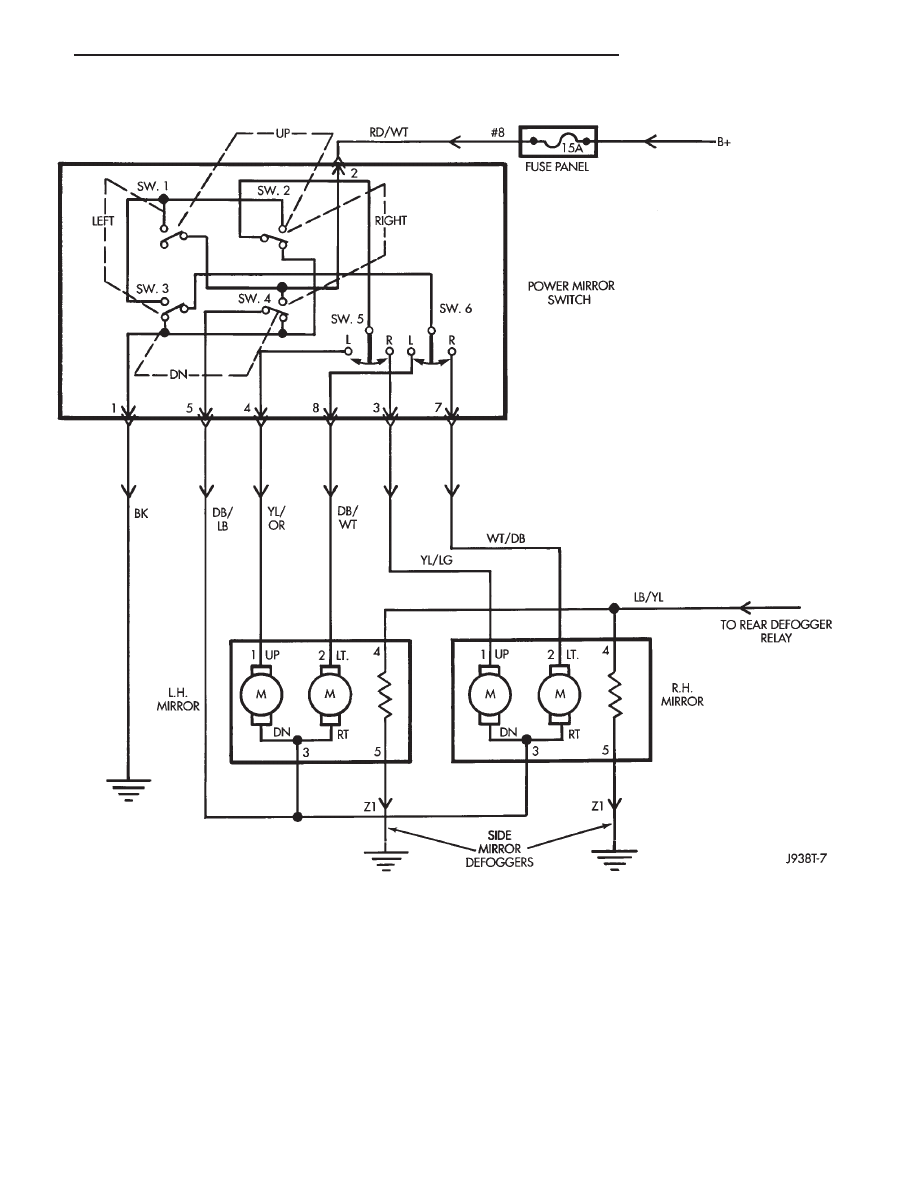
POWER MIRROR SCHEMATIC
Z
POWER MIRRORS
8T - 3
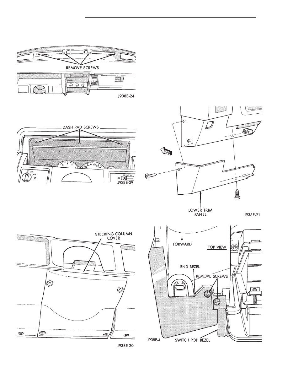
(8) Remove 4 screws in defroster duct opening hold-
ing dash pad (Fig. 6).
(9) Remove 3 screws above Instrument Panel clus-
ter holding dash pad (Fig. 7).
(10) Open glove box and remove 2 screws holding
dash pad.
(11) Remove dash pad pulling up to unsnap end
clips.
(12) Remove 4 screws holding the steering column
cover (Fig. 8).
(13) With driver’s door open remove 1 screw from
the side of the lower trim panel (Fig. 9).
(14) Remove 1 screw from bottom of lower trim
panel and pull panel off. There is also a clip holding
the panel to the instrument panel.
(15) Remove 1 screw holding top of mirror switch
bezel (Fig. 10).
(16) Remove 1 screw holding bottom of bezel (Fig.
11). Remove the mirror switch bezel far enough to
unplug connector.
(17) Depress locking tabs and remove switch from
bezel (Fig. 12).
(18) To install the switch, reverse the removal pro-
cedures.
Fig. 9 Lower Trim Panel
Fig. 10 Remove Screw Holding Top Of Bezel
Fig. 8 Steering Column Cover
Fig. 6 Upper Dash Pad Attaching Screws
Fig. 7 Remove Screws Holding Dash Pad
8T - 4
POWER MIRRORS
Z
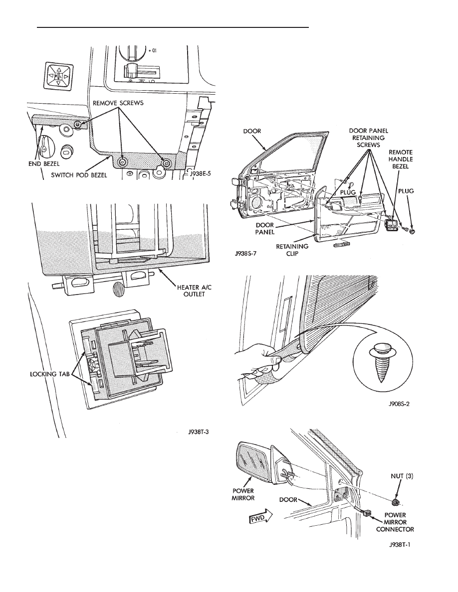
MIRROR ASSEMBLY REPLACEMENT
(1) Remove screw at top of trim panel near mirror
(Fig. 13).
(2) Remove screw from demister opening.
(3) Remove screw and door handle cover.
(4) Remove screw from under armrest.
(5) Remove screw from bottom of hand hold in arm-
rest.
(6) Remove the trim panel with a wide flat blade
tool (Fig. 14).
To aid in removal of the trim panel, start at
the bottom of the panel.
(7) Unplug mirror wiring from door harness at con-
nector (Fig. 15).
(8) Remove 3 nuts holding mirror and remove mir-
ror.
(9) To install the mirror, reverse the removal proce-
dures.
Fig. 13 Door Panel Removal
Fig. 14 Trim Panel Removal
Fig. 15 Power Mirror Removal/Installation
Fig. 11 Remove Screw Holding Bottom Of Bezel
Fig. 12 Power Mirror Switch Removal
Z
POWER MIRRORS
8T - 5
AUTOMATIC DAY/NIGHT REAR VIEW MIRROR
GENERAL
The Automatic Day/Night Mirror automatically
changes its reflectance to reduce glare in all types of
driving conditions. A thin layer of electrochromic ma-
terial between two pieces of conductive glass make up
the face of the mirror. As light conditions change, two
photocell sensors adjust the reflectance while reduc-
ing glare from headlamps approaching from the rear.
SENSORS
The mirror incorporates 2 sensors. The Ambient
sensor (forward facing) detects normal outside light
levels. The Headlamp sensor (rear facing) detects
light levels received at the rear window side of the
mirror. When the difference between the two levels
becomes too great (light level received at rear of mir-
ror is much higher than front of mirror), the mirror
begins to darken. The level of light required to darken
the mirror is controlled by the Mirror Switch.
SWITCH
The mirror switch allows the driver to adjust the
sensitivity of the mirror. In the LOW position, the
mirror is less sensitive to change while the HIGH
position causes the mirror to darken at a lower glare
level.
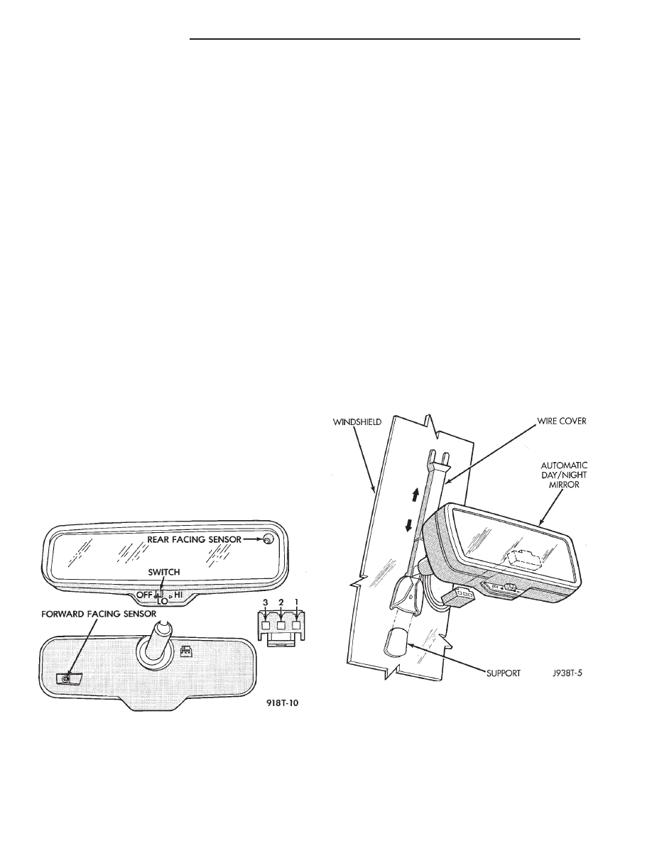
To test the operation:
• Turn ignition switch to the ON position with the
vehicle in park.
• Place mirror switch in either the low or high posi-
tion (Fig. 1).
• Cover the forward facing sensor with your hand to
keep out any ambient light.
• Shine a light into the rear facing sensor. Watch to
see if the mirror darkens.
With the mirror darkened, place the vehicle in re-
verse, the mirror should return to its normal condi-
tion.
If the above conditions are met the mirror is operat-
ing properly.
If the above conditions are not met, perform the
following voltage tests (Fig. 1).
Test 3 way connector harness.
(1) Pin 1 - Ignition Switch in RUN position, should
have battery voltage.
(2) Pin 2 - Should have continuity to ground.
(3) Pin 3 - When the transmission is in reverse,
should have battery voltage.
(4) If test is OK, replace Mirror.
(5) If not, refer to 8W - Wiring Diagrams to test the
circuits.
REPLACEMENT
(1) Remove wire cover by grasping lower portion of
wire cover and sliding into upper portion and off of
mirror base (Fig. 2).
(2) Unplug connector behind mirror.
(3) Remove screw holding mirror to windshield.
(4) Push mirror up far enough to clear the support
and remove mirror.
(5) To install mirror, reverse removal procedures
Fig. 1 Automatic Day/Night Mirror
Fig. 2 Automatic Mirror Removal
8T - 6
POWER MIRRORS
Z
Document Outline
Wyszukiwarka
Podobne podstrony:
93ZJ Secc 8R Power Seats
96ZJ 8T POWER MIRROR SYSTEMS
93ZJ Secc 8S Power Windows
93ZJ Secc 8P Power Door Locks
93ZJ Secc 11 Exhaust System and Intake Manifold
93ZJ Secc 8J Turn Signals and Hazard Warning Flashes
93ZJ Secc 8F Audio Systems
POWER MIRRORS
93ZJ Secc 16 Propeller Shafts
93ZJ Secc 6 Clutch
93ZJ Secc 8L Lamps
93ZJ Secc 8B Battery Starter Motor Generator Service
93ZJ Secc 8A Electrical Systems
93ZJ Secc 8M Restraint Systems
93ZJ Secc 22 Wheels and Tires
power mirrors
93ZJ Secc 25 Emission Control Systems
93ZJ Secc 0 Lubrication and Maintenance
93ZJ Secc 8G Horns
więcej podobnych podstron