
POWER DOOR LOCKS
CONTENTS
page
page
KEYLESS ENTRY . . . . . . . . . . . . . . . . . . . . . . . . . 5
POWER LOCKS
. . . . . . . . . . . . . . . . . . . . . . . . . . 1
POWER LOCKS
INDEX
page
page
Actuator Motor Stall Test
. . . . . . . . . . . . . . . . . . . . 2
Description
. . . . . . . . . . . . . . . . . . . . . . . . . . . . . . 1
Diagnosing Power Door Locks
. . . . . . . . . . . . . . . . 1
General
. . . . . . . . . . . . . . . . . . . . . . . . . . . . . . . . . 1
Liftgate Lock Actuator Replacement
. . . . . . . . . . . . 4
Solenoid and Latch Assembly Replacement
. . . . . . 3
Switch Replacement—Front Door
. . . . . . . . . . . . . . 2
Switch Replacement—Rear Door
. . . . . . . . . . . . . . 2
GENERAL
The door lock actuators, including liftgate, are con-
trolled by two-way switches. To lock the doors, push
either switch to the right. To unlock doors from inside
the vehicle push either switch to the left.
The power door locks do not lock or unlock the
doors from outside the vehicle. Insert the key into the
lock cylinder to lock or unlock each individual door or
use the keyless entry transmitter.
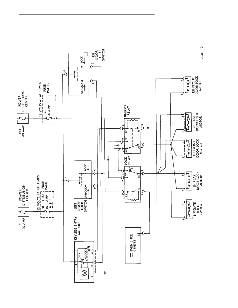
DESCRIPTION
The door locks are operated by reversible motors.
The voltage supply comes from the 20 amp mini fuse
F1 in the Power Distribution Center (PDC) to the 15
amp #8 fuse located in the fuse panel. Power then
goes to the left hand door lock switch. With the left
hand door lock switch in LOCK, voltage is applied
through the switch to the door Lock Relay coil. The
relay coil is energized which closes the circuit from
the F14 20 amp fuse to the lock motor. Fuse 14 is
supplied by a 40 amp maxi fuse in the PDC labeled
Fuse Block Feed. The motor is grounded by the un-
lock relay.
The LOCK function will not operate if:
• The chime module is not plugged in.
• The key is in the ignition, or the lights are ON,
while the driver’s door is open.
• The door lock inhibit feature of the chime module
is inoperable due to defective electronics in the chime.
In this case the operation is unpredictable.
The RH door lock window switch operates the same
as the driver’s door switch. The voltage and ground
paths are reversed to unlock the doors.
The power door lock operates with battery power
and, therefore, is independent of the ignition switch.
DIAGNOSING POWER DOOR LOCKS
If the vehicle has Keyless Entry and the door locks
operate properly using the door switches but do not
work with the transmitter, refer to Keyless Entry in
this group.
DOOR LOCKS DO NOT OPERATE USING DOOR
LOCK SWITCHES
For complete circuit diagrams refer to Group
8W - Wiring Diagrams.
Check fuses #8 and #14 in the fuse panel. Re-
place as required.
(1) Measure voltage at output side of fuses. Meter
should read battery voltage. If not, repair open in
circuit to fuse.
(2) Remove door switch and measure voltage at
terminal 4. Meter should read battery voltage. If not,
repair open circuit between fuse #8 and switch.
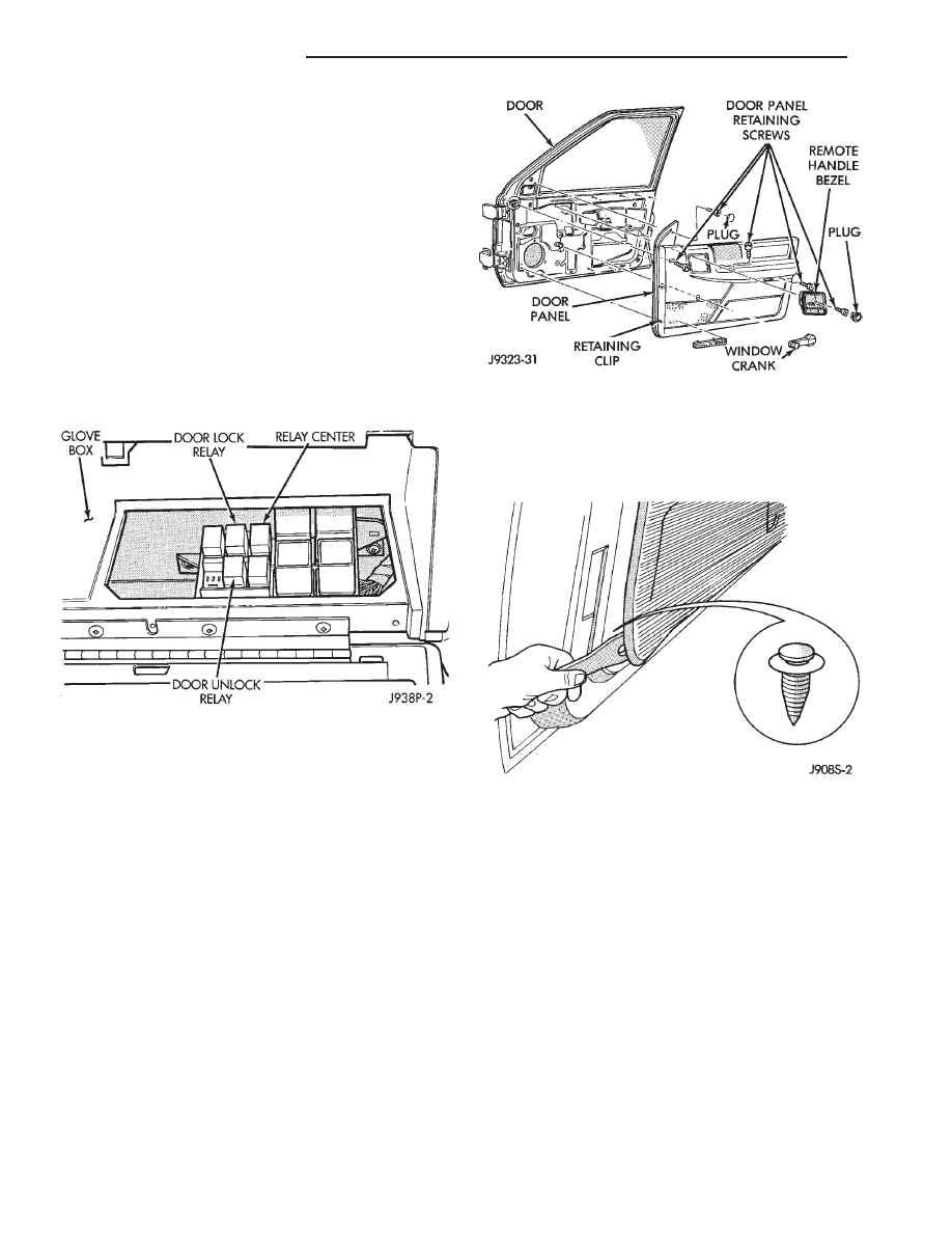
(3) Remove glove box bottom to access the relay
center.
(4) Measure resistance between Lock and Unlock
relay terminal 4 and ground. Meter should read zero
ohms. If not, repair open to ground.
(5) Measure voltage at terminal 2 of both the Lock
and Unlock relays. Meter should read battery voltage.
If OK, next step. If not, repair open to fuse #14.
(6) Measure resistance at terminal 5 of both the
Lock and Unlock relays. Meter should read zero
ohms. If not, repair open to ground.
Z
POWER DOOR LOCKS
8P - 1
(7) Hold left hand switch in LOCK position. Mea-
sure voltage at lock relay terminal 1. Meter should
read battery voltage. If OK, next step. If not, repair
open to left hand switch.
(8) Hold left hand switch in UNLOCK position.
Measure voltage at Unlock relay terminal 1. Meter
should read battery voltage. If OK, next step. If not,
repair open to left hand switch.
(9) Hold left hand switch in LOCK position. Mea-
sure voltage at Lock relay terminal 4. Meter should
read battery voltage. If OK, next step. If not, replace
Lock relay.
(10) Hold left hand switch in UNLOCK position.
Measure voltage at Unlock relay terminal 4. Meter
should read battery voltage. If OK, check connections
and door motor. If not, replace Unlock relay.
(11) Repeat procedures for RH switch.
ACTUATOR MOTOR STALL TEST
To test the actuator motor, attach an ammeter in
series with the motor and operate the door switch.
Replace the actuator motor if current draw exceeds 8
amps at room temperature or if the actuator does not
complete its travel in less than one second. Refer to
Removal procedures.
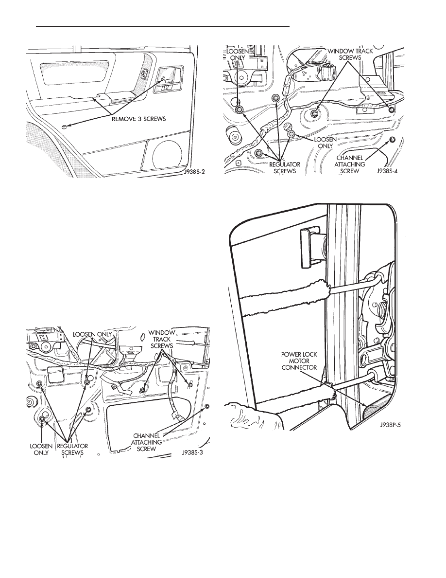
SWITCH REPLACEMENT—FRONT DOOR
(1) Remove screw at top of trim panel near mirror
(Fig. 2).
(2) Remove screw from demister opening at front of
door.
(3) Remove screw and door handle cover.
(4) Remove screw from under armrest.
(5) Remove screw from bottom of hand hold in arm-
rest.
CAUTION: The wiring harness to the door switches
is just long enough to allow installation. If trim panel
is pulled off by hand the switch may be pulled apart.
Use a door clip tool to prevent damaging the
switches.
(6) Remove the trim panel with a wide flat blade
tool (Fig. 3).
To aid in removal of the trim panel, start at
the bottom of the panel.
(7) Unplug electrical connector from switch.
(8) Remove switch from door panel.
(9) Install a new switch.
(10) Install door trim panel by reversing the re-
moval procedures.
SWITCH REPLACEMENT—REAR DOOR
(1) Remove screw and door handle cover (Fig. 4).
(2) Remove screw from under armrest.
(3) Remove screw from bottom of hand hold in arm-
rest.
CAUTION: The wiring harness to the door switches
is just long enough to allow installation. If trim panel
is pulled off by hand the switch may be pulled apart.
Use a door clip tool to prevent damaging the
switches.
Fig. 1 Door Lock/Unlock Relays
Fig. 2 Door Panel Removal
Fig. 3 Trim Panel Removal
8P - 2
POWER DOOR LOCKS
Z
(4) Remove the trim panel with a wide flat blade
tool (Fig. 3).
To aid in removal of the trim panel, start at
the bottom of the panel.
(5) Remove switch from door panel.
(6) Install a new switch.
(7) Install door trim panel by reversing the removal
procedures.
SOLENOID AND LATCH ASSEMBLY REPLACEMENT
(1) Remove door panel as described in Switch Re-
placement.
(2) Remove 1 bolt holding bottom of window track
to door (Figs. 5 and 6).
(3) Disconnect 4 linkage rods from their clips (Figs.
7 and 8).
(4) Unplug wire harness connector from lock motor.
(5) Remove 3 torx head screws retaining the latch
(Figs. 9 and 10).
(6) Place the lock solenoid, latch and remote control
rods in the door.
(7) Attach the lock solenoid to the door panel with
3 torx head screws. Tighten screws to 11 N
Im (95 in.
lbs.).
(8) Install 4 linkage rods.
(9) Using 3M 08044 or 3M 08041 adhesive/sealant,
install the plastic water dam sheet.
(10) Place the trim panel in the installation posi-
tion and press in the nylon retainers.
(11) Install the door panel attaching screws.
Fig. 4 Trim Panel Attachment
Fig. 5 Window Track Attaching Bolts—Front Door
Fig. 6 Window Track Attaching Bolts—Rear Door
Fig. 7 Power Lock Motor—Front Door
Z
POWER DOOR LOCKS
8P - 3
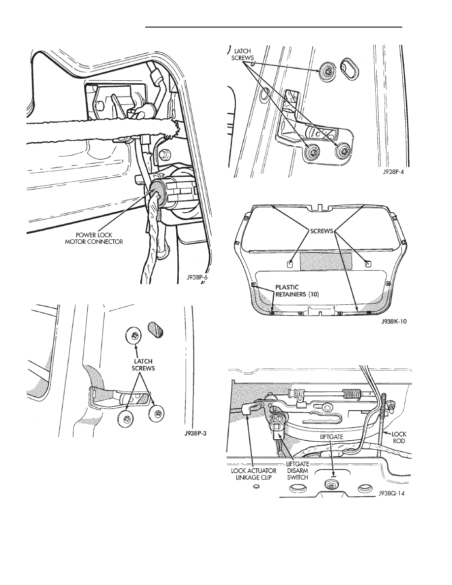
LIFTGATE LOCK ACTUATOR REPLACEMENT
(1) Remove 5 screws holding liftgate interior trim
panel.
To aid in removal of the trim panel, start at
the bottom of the panel.
(2) Remove the trim panel with a wide flat blade
tool (Fig. 11).
(3) Disconnect the lock actuator linkage clip at the
handle (Fig. 12).
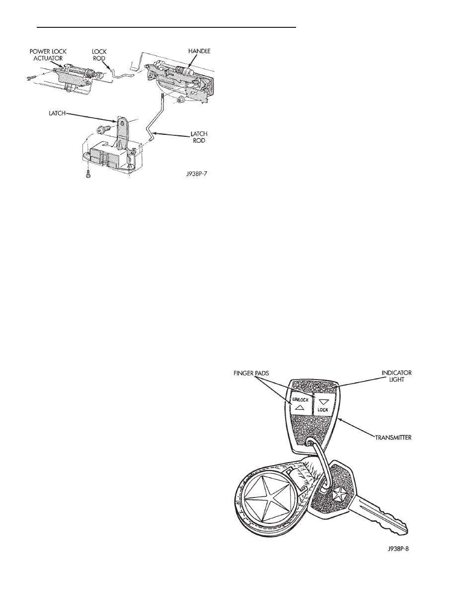
(4) Remove 2 actuator retaining screws (Fig. 13).
(5) Remove the actuator.
Fig. 8 Power Lock Motor—Rear Door
Fig. 9 Latch Removal/Installation—Front Door
Fig. 10 Latch Removal/Installation—Rear Door
Fig. 11 Liftgate Trim Panel Removal
Fig. 12 Lock Actuator Linkage Clip
8P - 4
POWER DOOR LOCKS
Z
(6) To install the actuator, reverse the removal pro-
cedures.
(7) Tighten the actuator screws to 3 N
Im (28 in.
lbs.) torque.
KEYLESS ENTRY
INDEX
page
page
Diagnosing Power Door Locks
. . . . . . . . . . . . . . . . 6
Door Lock/Unlock Relay Replacement
. . . . . . . . . . 9
Receiver
. . . . . . . . . . . . . . . . . . . . . . . . . . . . . . . . 6
Receiver Service
. . . . . . . . . . . . . . . . . . . . . . . . . . 8
System Description
. . . . . . . . . . . . . . . . . . . . . . . . 5
System Operation
. . . . . . . . . . . . . . . . . . . . . . . . . 6
Transmitter
. . . . . . . . . . . . . . . . . . . . . . . . . . . . . . 5
Transmitter Programming
. . . . . . . . . . . . . . . . . . . . 6
Transmitter Service
. . . . . . . . . . . . . . . . . . . . . . . . 8
SYSTEM DESCRIPTION
The keyless entry system consists of a portable
remote control transmitter and a receiver mounted in
the overhead console or in the dome-lamp housing.
System operation is based on a coded infrared signal
from the transmitter to the receiver. The transmitter
is programmed into the receiver providing the correct
programming sequence is met.
When the keyless entry system is activated, the
corresponding relay operates to supply voltage to the
motors. The use of either relay determines the polar-
ity of the voltage that is supplied to the door lock
motors.
When the keyless entry system is used, the trans-
mitter sends a signal to the keyless entry module. If
the doors are unlocked, the module activates a tran-
sistor switch to apply voltage to the lock relay coil.
The coil is energized to close the normally open con-
tacts of the lock relay. Battery voltage from the relay
is applied to the door lock motors to lock the doors.
Current flows in the same path to ground as it does
when the master door lock switch is used.
When the doors are locked, the keyless entry mod-
ule applies voltage to the unlock relay coil and a
similar action takes place to unlock the doors.
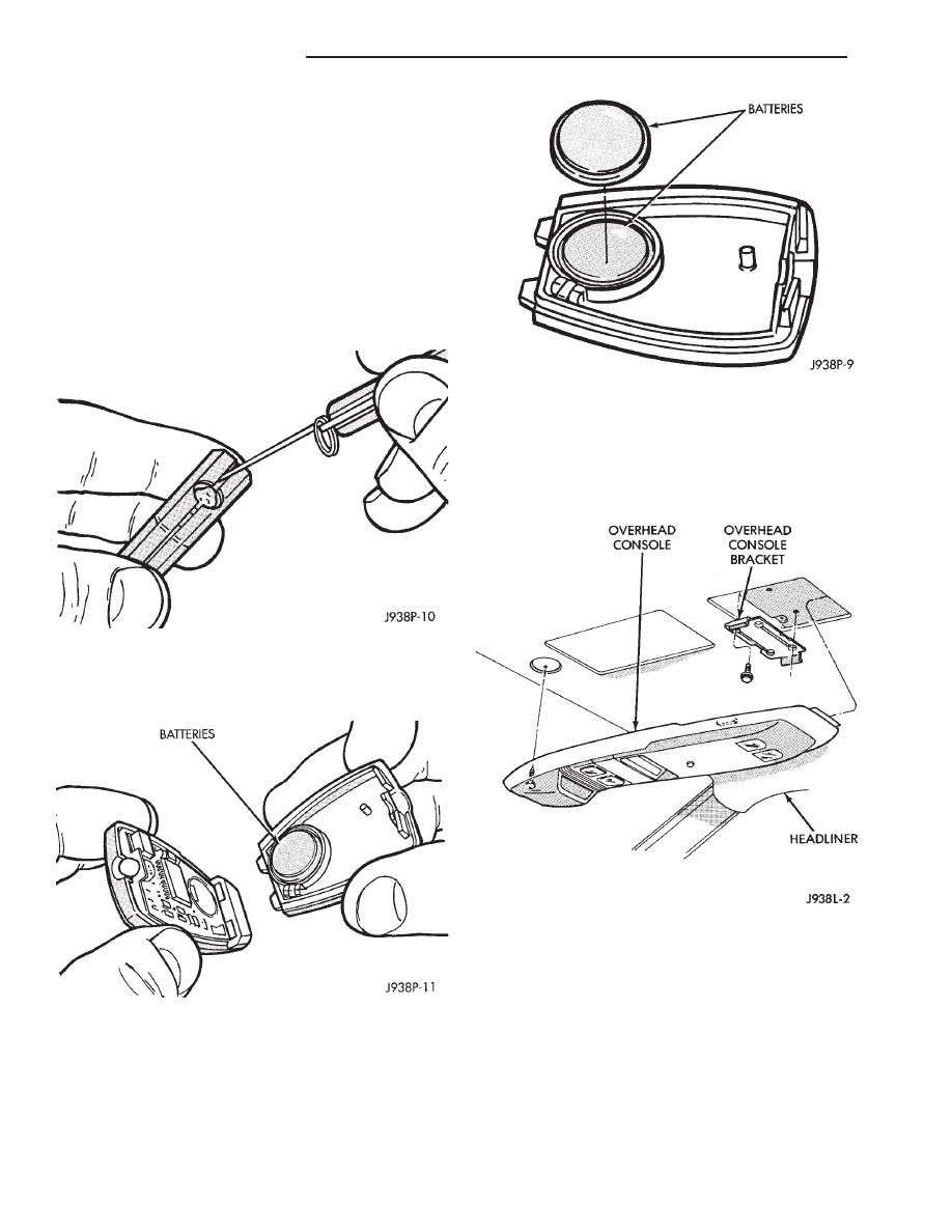
TRANSMITTER
The pocket size, solid state transmitter operates on
2, 3 volt lithium (CR1616) batteries (Fig. 1). The
transmitter is activated by pressing either the lock
Fig. 1 Keyless Entry Transmitter
Fig. 13 Power Lock Actuator Removal/Installation
Z
POWER DOOR LOCKS
8P - 5

or unlock button. This closes the internal contacts
that complete the battery circuit.
The battery voltage activates the transmitter diode
which in turn generates a coded infrared signal. The
signal is transmitted as pulses of infrared light.
If the red LED on the side of the transmitter case
does not light when the transmitter is activated, the
batteries are low.
RECEIVER
The receiver is in circuit with the electric door lock
system. The coded infrared signal is picked up by the
receiver diode and is shaped, amplified and decoded
by an integrated circuit within the receiver. If the
signal code received matches the code in the receiver
memory
circuit,
the
receiver
triggers
the
door
lock/unlock relays. The relays complete the circuit to
the electric door lock solenoid to either lock or unlock
the doors.
SYSTEM OPERATION
To activate the system, aim the transmitter diode
toward the receiver and press the transmitter signal
button to lock or unlock the doors as desired.
Effective transmitter range is 4.75 meters (15 ft.)
with the transmitter positioned no more than 45 de-
grees from the receiver centerline.
For complete circuit diagrams refer to Group
8W - Wiring Diagrams.
TRANSMITTER PROGRAMMING
Up to 4 Transmitter Identification Codes (TIC’s) can
be programed into the receiver at any given time.
(1) Open the driver’s door of the vehicle. Leave it
open through the programming procedure.
(2) Move the mechanical door lock lever to the
LOCK position.
(3) Insert the ignition key and turn it to the RUN
position.
(4) Turn the ignition to the RUN position. Within
20 seconds, aim a transmitter at the receiver dome
and press the lock button, for at least 5 seconds. Once
the receiver accepts the programming code the driv-
er’s door will unlock.
(5) Once
the
first
transmitter
has
been
pro-
grammed, additional transmitters (up to 4) may be
programmed into the receiver. Within 20 seconds of
the previous transmitter programming, move the me-
chanical door lock lever to the Lock position. Aim
another transmitter at the receiver dome and press
the LOCK button for at least 5 seconds. The door lock
will cycle again.
(6) To lock the programmed codes into the receiver,
the ignition must be turned off and back on within 20
seconds after programming the last transmitter’s
code. At that time, all previous codes are erased from
the module.
DIAGNOSING POWER DOOR LOCKS
NO DOOR LOCKS OPERATE, USING TRANS-
MITTER
(1) Measure resistance at Keyless entry module ter-
minal 10. Meter should read zero ohms. If not, repair
open to ground.
(2) Measure voltage at Keyless entry module termi-
nal 1. Meter should read battery voltage. Battery
voltage must be at least 9 volts for this system
to operate. If not, repair open to Dome fuse.
(3) Jumper test leads Keyless entry module termi-
nal 1 to terminal 3. Doors should lock. If OK, replace
module. If not, repair open from terminal 3 to Lock
relay terminal 5.
(4) Jumper test leads Keyless entry module termi-
nal 1 to terminal 4. Door should unlock. If OK, re-
place module. If not, repair open from terminal 4 to
Unlock relay terminal 5.
8P - 6
POWER DOOR LOCKS
Z
POWER
DOOR
LOCKS
Z
POWER DOOR LOCKS
8P - 7
TRANSMITTER SERVICE
If the receiver malfunctions, only the receiver will
have to be replaced. The new receiver will have to be
reprogrammed. If a transmitter is lost, replace the
transmitter and reprogram the receiver.
Batteries may not be supplied with some re-
placement transmitters. Be sure to check a re-
placement transmitter before attempting to ac-
tivate the system.
TRANSMITTER BATTERY REPLACEMENT
(1) Separate the transmitter at the middle seam
(Fig. 2).
(2) Remove and discard the old batteries (Figs. 3,
4).
(3) Install the new CR 1616 batteries. Be sure the
batteries are installed according to polarity as shown
on the transmitter battery receptacles.
(4) Assemble the transmitter and verify the correct
battery installation. The voltage indicator light will
glow when the batteries are properly installed.
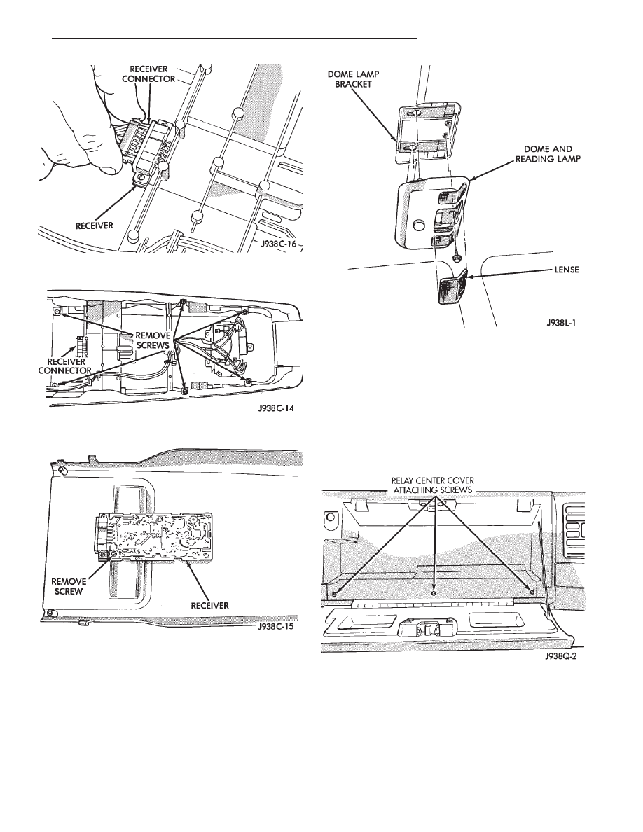
RECEIVER SERVICE
WITH OVERHEAD CONSOLE
(1) Remove console forward mounting screw (Fig.
5).
(2) Unplug Trip Computer harness connector.
(3) Slide console forward until the console detaches
from the rear mounting bracket.
(4) Unplug keyless entry harness connector (Fig. 6).
(5) Remove 6 screws holding rear half of console
(Fig. 7).
(6) Release 4 clips, 2 front and 2 rear, and separate
cover out from console.
(7) Remove the screw and the printed circuit board
can be removed (Fig. 8).
Fig. 2 Separate Transmitter Halves
Fig. 3 Battery Removal
Fig. 4 Battery Installation
Fig. 5 Remove/Install Overhead Console
8P - 8
POWER DOOR LOCKS
Z
(8) To install the overhead console, reverse the re-
moval procedures.
WITHOUT OVERHEAD CONSOLE
(1) Remove 1 screw attaching the dome lamp hous-
ing to the roof (Fig. 9).
(2) Push the housing toward the front of the vehi-
cle to disengage retainers.
(3) Unplug the harness connectors.
(4) Release the circuit board connector from its
mounting location.
(5) Remove circuit board from housing.
(6) Reverse the removal procedures to install the
receiver.
DOOR LOCK/UNLOCK RELAY REPLACEMENT
(1) Open glove box and remove 3 screws holding
relay center cover (Fig. 10).
Fig. 6 Keyless Entry Harness Connector
Fig. 7 Rear Overhead Console Panel Removal
Fig. 8 Receiver Removal/Installation
Fig. 9 Remove/Install Dome Lamp Housing
Fig. 10 Relay Center Cover
Z
POWER DOOR LOCKS
8P - 9
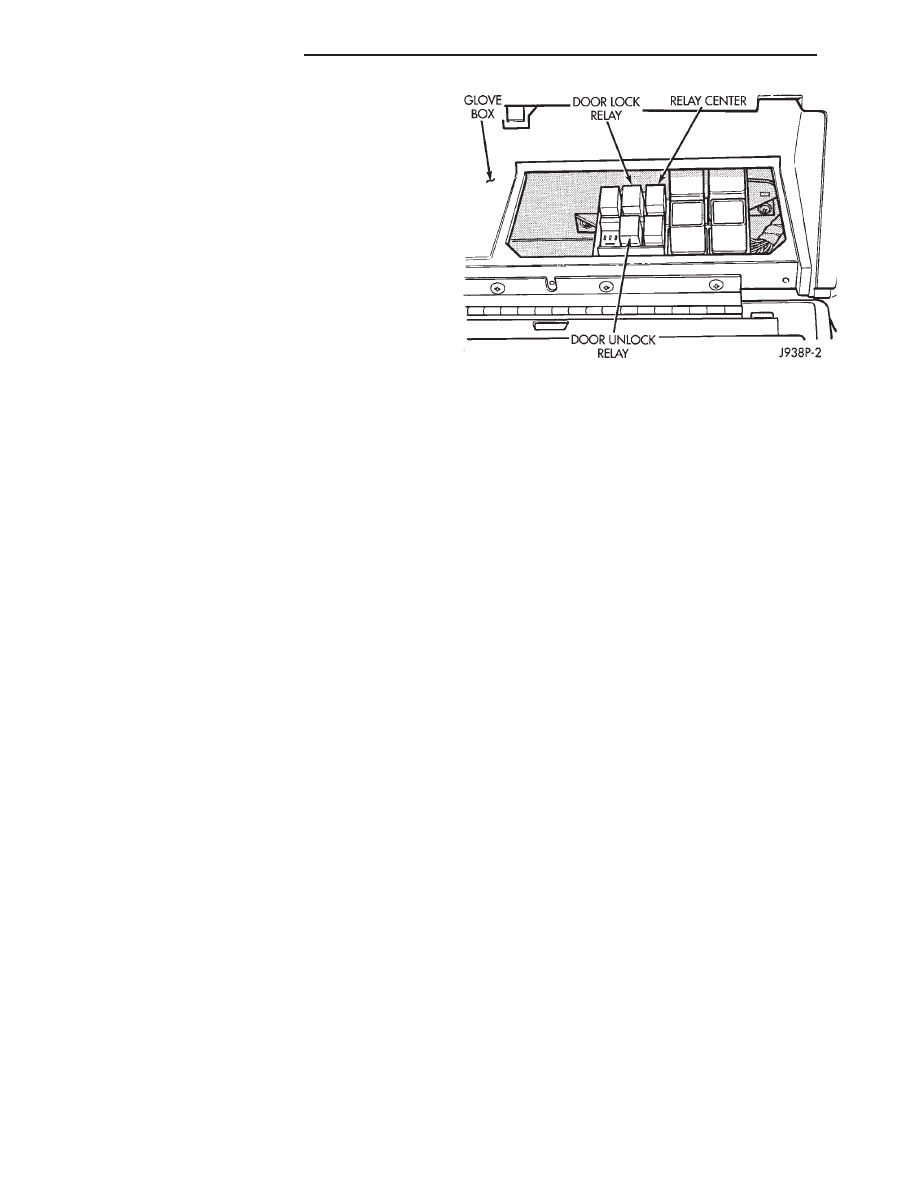
(2) Remove lock or unlock relay as required (Fig.
11).
Fig. 11 Door Lock/Unlock Relays
8P - 10
POWER DOOR LOCKS
Z
Document Outline
- POWER DOOR LOCKS
Wyszukiwarka
Podobne podstrony:
POWER DOOR LOCKS
93ZJ Secc 8R Power Seats
93ZJ Secc 8T Power Mirrors
93ZJ Secc 8S Power Windows
BMW E38 schematic Power door locks
door locks power
73 Anti Theft and Door Locks
11701 LEBARON COUPE CHRYSLER 3 5 WIRE DOOR LOCKS ALERT SHELBY UNITS
93ZJ Secc 11 Exhaust System and Intake Manifold
93ZJ Secc 8J Turn Signals and Hazard Warning Flashes
12856 BOXSTER PORSCHE 1 WIRE DOOR LOCKS JBS UNITS
93ZJ Secc 8F Audio Systems
93ZJ Secc 16 Propeller Shafts
93ZJ Secc 6 Clutch
93ZJ Secc 8L Lamps
Power Door Lock Circuit
93ZJ Secc 8B Battery Starter Motor Generator Service
93ZJ Secc 8A Electrical Systems
93ZJ Secc 8M Restraint Systems
więcej podobnych podstron