LAMPS
CONTENTS
page
page
BULB APPLICATION
. . . . . . . . . . . . . . . . . . . . . 17
DIAGNOSTIC PROCEDURES
. . . . . . . . . . . . . . . . 1
EXTERIOR LAMP SYSTEMS
. . . . . . . . . . . . . . . 12
GENERAL INFORMATION
. . . . . . . . . . . . . . . . . . 1
INTERIOR LAMPS . . . . . . . . . . . . . . . . . . . . . . . . 9
SERVICE PROCEDURES
. . . . . . . . . . . . . . . . . . . 3
GENERAL INFORMATION
Each vehicle is equipped with various lamp assem-
blies. A good ground is necessary for proper lighting
operation. Grounding is provided by the lamp socket
when it comes in contact with the metal body, or
through a separate ground wire.
When changing lamp bulbs check the socket for
corrosion. If corrosion is present, clean it with a wire
brush. Coat the inside of the socket lightly with Mo-
par
t Multi-Purpose Grease or equivalent.
Aero headlamps use a replaceable bulb that is
mounted in a molded plastic lens.
DIAGNOSTIC PROCEDURES
Always begin any diagnosis by testing all of the
fuses and circuit breakers in the system. Refer to
Group 8W, Wiring Diagrams.
LEFT HAND SWITCH POD
The multi-function switch pod contains electrical
circuitry for:
• Auto Headlamps
• Park Lamps
• Headlamps
• Low Beam/Fog Lamp
• Instrument Lamp Intensity
• Dome Lamp
This multi-function switch pod is mounted to the
left hand side of the instrument panel. Should any
function of the switch fail, other than illumination
bulbs, the entire switch pod must be replaced.
The multi-function switch also serves as a fog lamp
lock-out circuit. The circuit to the fog lamp switch is
completed only when the dimmer switch is in the low
beam position.
TURN SIGNAL/DIMMER SWITCH
This integrated switch is mounted to the left of the
steering column. Should any function of this switch
fail, the entire switch must be replaced. Refer to
Group 8J, Turn Signals And Hazard Warning Flasher
for service procedures.
DIMMER SWITCH TEST
(1) Disconnect battery negative cable.
(2) Remove tilt lever.
(3) Remove screws along bottom edge of steering
column.
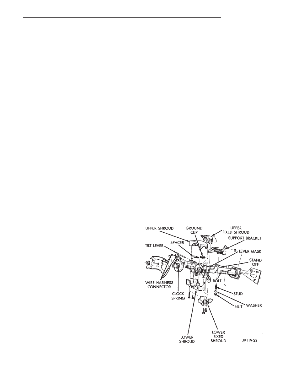
(4) Remove upper and lower shrouds to gain access
to the switch connector (Fig. 1).
Fig. 1 Steering Column Covers
Z
LAMPS
8L - 1
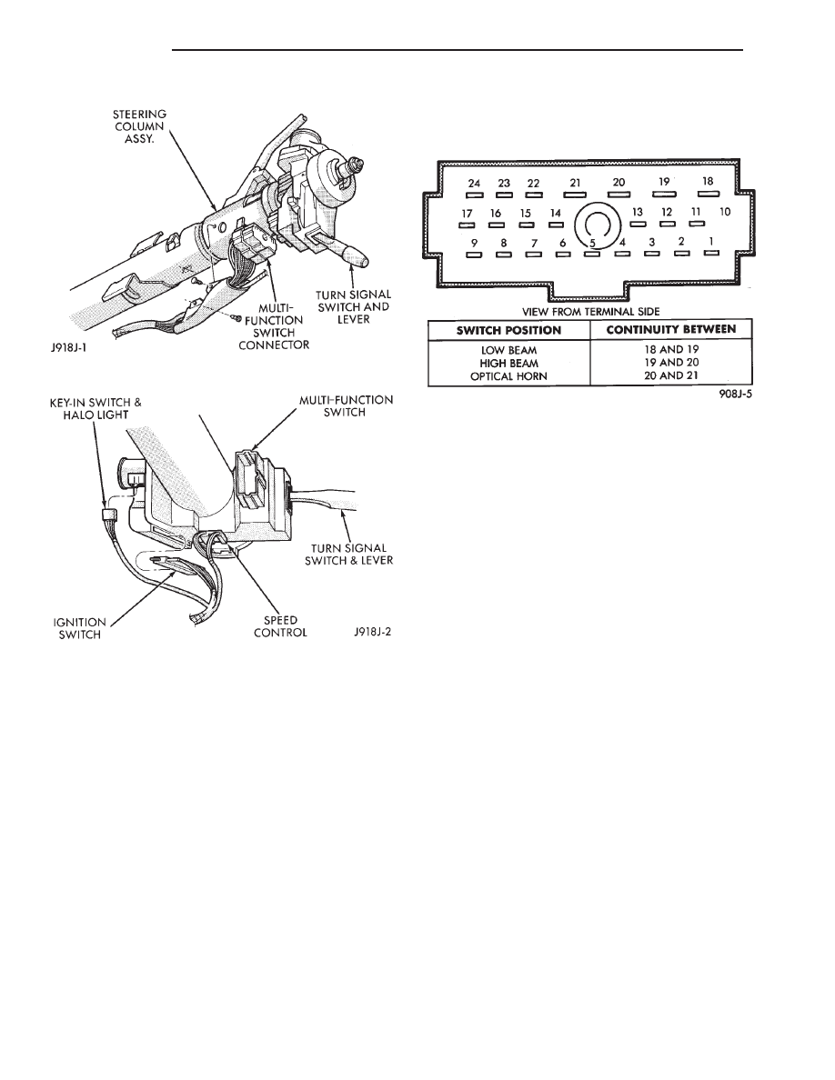
(5) Remove switch connector (Figs. 2 and 3).
(6) Use an ohmmeter to test for continuity between
the terminals of the switch as shown in the chart
(Fig. 4).
(7) Refer to Service Procedures for assembly.
Fig. 2 Multi-function Switch Connector
Fig. 3 Steering Column Connectors
Fig. 4 Dimmer Switch Continuity Chart
8L - 2
LAMPS
Z

SERVICE PROCEDURES
INDEX
page
page
Aero Headlamp Replacement
. . . . . . . . . . . . . . . . . 3
Backup Lamps
. . . . . . . . . . . . . . . . . . . . . . . . . . . . 6
Center High Mounted Stop Lamp (CHMSL)
. . . . . . 7
Fog Lamp Switch Replacement
. . . . . . . . . . . . . . . 6
Fog Lamps
. . . . . . . . . . . . . . . . . . . . . . . . . . . . . . 4
Headlamp Alignment
. . . . . . . . . . . . . . . . . . . . . . . 3
Headlamp Alignment Preparation
. . . . . . . . . . . . . . 3
Headlamp Switch
. . . . . . . . . . . . . . . . . . . . . . . . . . 6
Headlamp/Fog Lamp Adjustment Using Alignment
Screen
. . . . . . . . . . . . . . . . . . . . . . . . . . . . . . . . 3
License Plate Lamp
. . . . . . . . . . . . . . . . . . . . . . . . 7
Parking Lamp Bulb/Lens Replacement
. . . . . . . . . . 4
Rear Side Marker Lamp
. . . . . . . . . . . . . . . . . . . . . 7
Tail and Stop Lamps
. . . . . . . . . . . . . . . . . . . . . . . 6
Turn Signal and Side Marker Lamp
. . . . . . . . . . . . 4
Turn Signal Lamp
. . . . . . . . . . . . . . . . . . . . . . . . . 6
Turn Signal/Dimmer Switch
. . . . . . . . . . . . . . . . . . 6
Underhood Lamp
. . . . . . . . . . . . . . . . . . . . . . . . . . 8
HEADLAMP ALIGNMENT
Headlamps can be aligned using the screen method
provided in this section. Alignment Tool C4466-A or
equivalent can also be used. Refer to instructions
provided with the tool for proper procedures. The
preferred headlamp alignment setting is 0 for
the left/right adjustment and 1
( down for the
up/down adjustment.
HEADLAMP ALIGNMENT PREPARATION
(1) Verify headlamp dimmer switch and high beam
indicator operation.
(2) Correct defective components that could hinder
proper headlamp alignment.
(3) Verify proper tire inflation.
(4) Clean headlamp lenses.
(5) Verify that luggage area is not heavily loaded.
(6) Fuel tank should be FULL. Add 2.94 kg (6.5
lbs.) of weight over the fuel tank for each estimated
gallon of missing fuel.
HEADLAMP/FOG LAMP ADJUSTMENT USING
ALIGNMENT SCREEN
ALIGNMENT SCREEN PREPARATION
(1) Position vehicle on a level surface. Perpendicu-
lar to a flat wall 7.62 meters (25 ft) away from front
of headlamp lens.
(2) If necessary, tape a line on the floor 7.62 meters
(25 ft) away from and parallel to the wall (Fig. 1).
(3) From the floor up 1.27 meters (5 ft), tape a line
on the wall at the centerline of the vehicle. Sight
along the centerline of the vehicle to verify accuracy
of line placement.
(4) Rock vehicle side-to-side three times to allow
suspension to stabilize.
(5) Jounce front suspension three times by pushing
downward on front bumper and releasing.
(6) Measure the distance from the center of head-
lamp lens to the floor. Transfer measurement to the
alignment screen (with tape). Use this line for
up/down adjustment reference.
(7) Measure distance from the centerline of the ve-
hicle to the center of each headlamp being aligned.
Transfer measurements to screen (with tape) to each
side of vehicle centerline. Use these lines for left/right
adjustment reference.
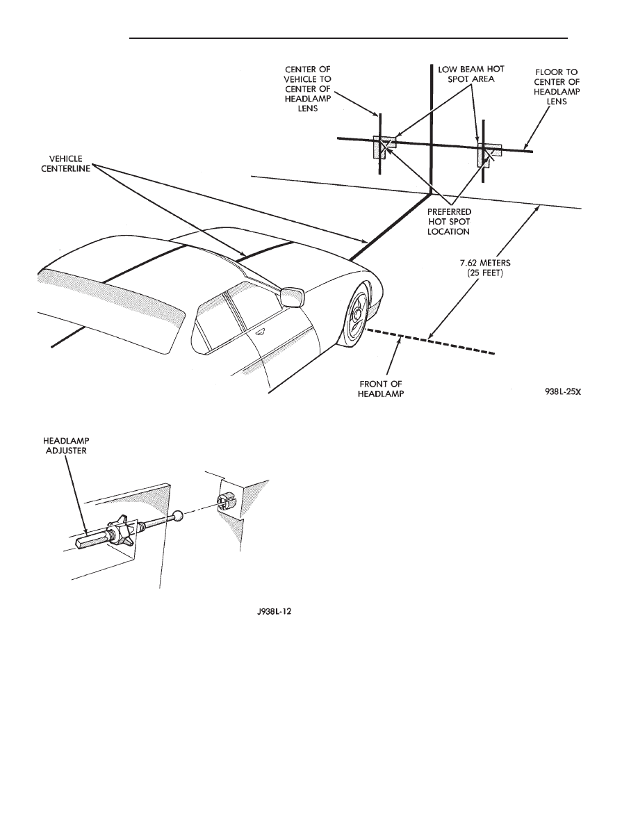
HEADLAMP ADJUSTMENT
A properly aimed low beam will project the top edge
of high intensity pattern on the screen from 50 mm (2
in.) above to 50 mm (2 in.) below headlamp center-
line. The side-to-side left edge of high intensity pat-
tern should be from 50 mm (2 in.) left to 50 mm (2 in.)
right of headlamp centerline (Fig. 1). The preferred
headlamp alignment is 0 for the left/right ad-
justment and 1
( down for the up/down adjust-
ment. The high beams on a vehicle with aero head-
lamps cannot be aligned. The high beam pattern
should be correct when the low beams are aligned
properly.
To adjust headlamp aim, rotate alignment screws.
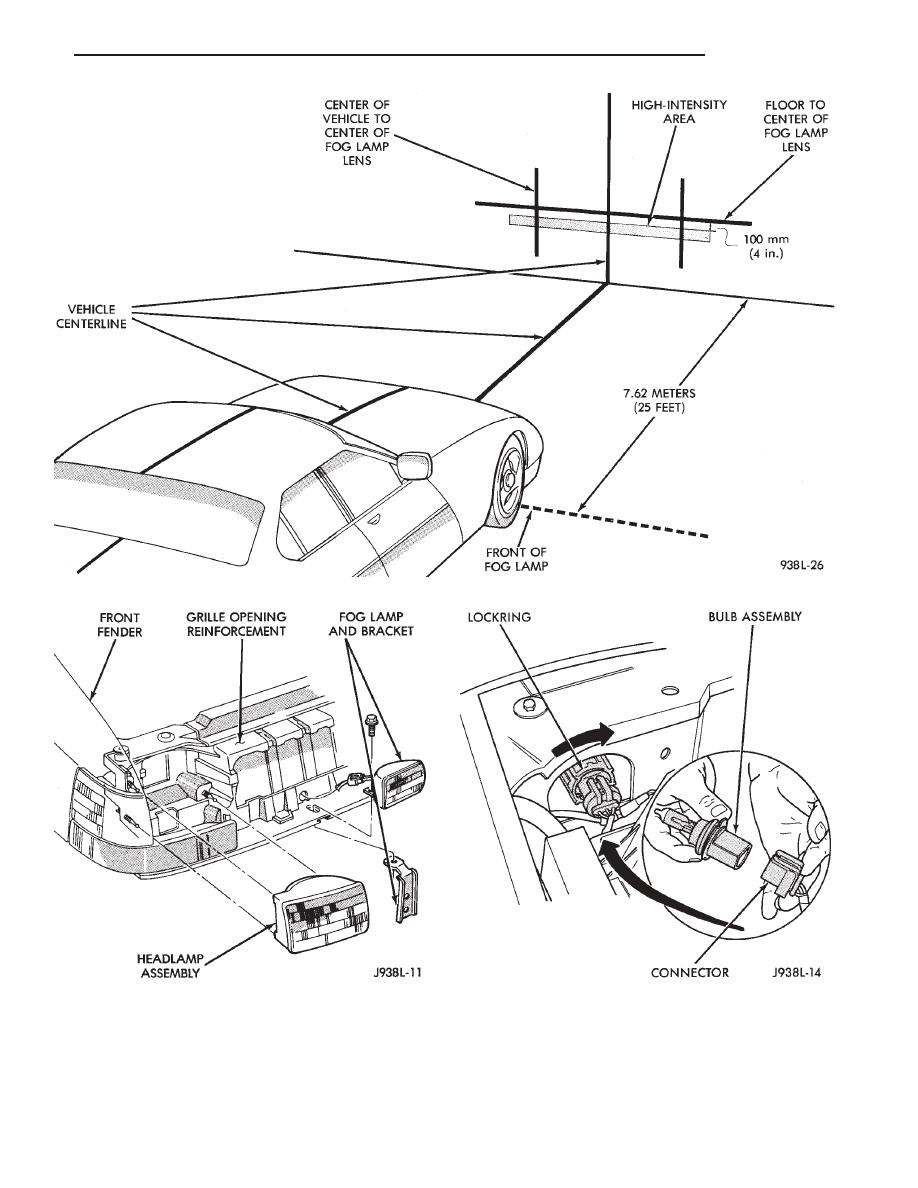
FOG LAMP ADJUSTMENT
Prepare an alignment screen. A properly aligned fog
lamp will project a pattern on the alignment screen
100 mm (4 in.) below the fog lamp centerline and
straight ahead (Fig. 3).
AERO HEADLAMP REPLACEMENT
CAUTION: Do not touch the bulb glass with fingers
or other oily surfaces. Reduced bulb life will result.
(1) Grasp lower edge of headlamp lens. Pull
straight back (away) from grille opening reinforce-
ment (GOR). Disengage lower adjuster pivots from
lens assembly (Fig. 4).
(2) Grasp upper edge of headlamp lens. Pull
straight back from grille opening reinforcement
(GOR). Disengage upper adjuster pivot from lens as-
sembly.
(3) Locate and disconnect the 3 wire connector be-
hind the headlamp.
Z
LAMPS
8L - 3
HEADLAMP BULB REMOVAL
(1) Lift hood to access lamps.
(2) Reach into engine compartment and locate lock
ring supporting the headlamp bulb assembly.
(3) Rotate the lock ring 1/8 turn counterclockwise
(Fig. 5).
(4) Pull the bulb (9004) straight out from the hous-
ing. This is a halogen bulb, take care not to touch it
with your fingers.
(5) Replace by seating the assembly in the lamp
housing and turning the lock ring 1/8 turn clockwise
to secure.
PARKING LAMP BULB/LENS REPLACEMENT
The parking lamp is mounted on the side of the
GOR next to headlamp assembly.
(1) Open hood.
(2) Remove two screws which hold the parking
lamp in position (Fig. 6).
(3) Disengage lamp and grasp and pull bulb (194
NA) to remove.
To install, reverse the removal procedure.
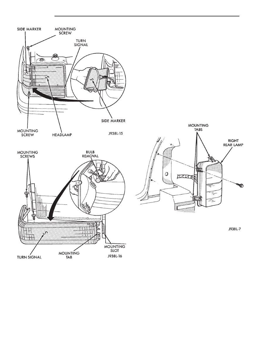
TURN SIGNAL AND SIDE MARKER LAMP
(1) The parking lamp must be removed to get to
attaching screws for this lamp.
(2) Remove the two screws and slide lamp outboard
to expose the bulb (Fig. 7).
(3) To replace turn signal bulb, press in on bulb
(1295na) and rotate 1/4 turn to remove.
(4) To replace sidemarker bulb (194na) grasp and
pull from lamp.
(5) After replacing bulb, slide lamp into slot pro-
vided on inboard side of headlamp assembly. Replace
two screws and replace parking lamp.
FOG LAMPS
Fog lamps are turned OFF by the circuit relay
Fig. 1 Headlamp Alignment Screen —Typical
Fig. 2 Aero Headlamp Alignment
8L - 4
LAMPS
Z
when high beam driving lamps are turned ON.
Fog lamps may be operated ONLY when low beam
headlamps are ON. If the headlamps are switched to
high beam, the fog lamps will turn OFF. The fog lamps
will go back on when the high beams are switched OFF.
FOG LAMP BULB/LENS REPLACEMENT
CAUTION: Do not touch the bulb glass with fingers
or other oily surfaces. Reduced bulb life will result.
(1) Remove center pivot bolt and disconnect wire
Fig. 3 Fog Lamp Alignment —Typical
Fig. 4 Headamp Removal
Fig. 5 Headlamp Bulb Removal
Z
LAMPS
8L - 5
connector.
(2) Remove the 2 screws attaching the lens to the
lamp housing. Remove lens from lamp housing.
(3) Remove spring clip holding bulb to lens.
(4) Disconnect 2 wire connectors at bulb.
(5) Remove bulb element from lens.
(6) To install, reverse the removal procedure.
HEADLAMP SWITCH
To remove or replace headlamp switch. Refer to
Group 8E, Instrument Panel and Gauges.
TURN SIGNAL/DIMMER SWITCH
To remove or replace dimmer switch, Refer to Group
8J, Turn Signals and Hazard Flasher.
FOG LAMP SWITCH REPLACEMENT
The fog lamp switch is integrated into the head-
lamp switch. The switch is located on the left hand
side of instrument panel.
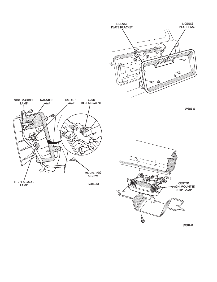
TAIL AND STOP LAMPS
To remove or replace bulbs.
(1) Remove three lamp screws and separate lamp
from body (Fig. 8).
(2) Grip top bulb socket and rotate counterclock-
wise. Separate socket and bulb from lens (Fig. 9).
(3) Rotate bulb in socket counterclockwise. Remove
bulb from socket.
To install, reverse the removal procedures.
BACKUP LAMPS
To remove or replace backup lamp bulbs:
(1) Remove three lamp screws and separate lamp
from the body (Fig. 8).
(2) Grip second bulb socket from top and rotate
counterclockwise. Separate socket from lamp (Fig. 9).
(3) Rotate bulb in the socket counterclockwise. Re-
move bulb from socket.
To install reverse the removal procedures.
BACKUP LAMP SWITCH
The backup lamp switch service instructions can be
found in Group 21, Transmission.
TURN SIGNAL LAMP
(1) Remove three lamp screws and separate the
lamp from body (Fig. 8).
Fig. 6 Parking Lamp Removal
Fig. 7 Turn Signal And Side Marker
Fig. 8 Rear Lamps
8L - 6
LAMPS
Z
(2) Grip bottom bulb socket and rotate counter-
clockwise. Separate socket from lamp (Fig 9).
(3) Rotate bulb in socket counterclockwise. Remove
bulb from socket.
To install, reverse the removal procedure.
REAR SIDE MARKER LAMP
The rear side marker lamp is incorporated into the
tail lamp.
(1) Remove three lamp screws and separate lamp
from body (Fig. 8).
(2) Grip bulb socket located on the side of lens.
Rotate counterclockwise. Separate socket from lamp
(Fig. 9).
(3) Rotate bulb in the socket counterclockwise. Re-
move bulb from socket (Fig. 9).
To install, reverse the removal procedure.
LICENSE PLATE LAMP
REMOVAL
(1) Remove screws and license plate lamp visor
from liftgate (Fig. 10).
(2) Remove bulb from lamp socket.
INSTALLATION
(1) Install a bulb in lamp socket.
(2) Position license plate lamp visor on liftgate and
install screws (Fig 10).
CENTER HIGH MOUNTED STOP LAMP (CHMSL)
The CHMSL is mounted at the top of the rear
window (Fig. 11).
(1) Raise liftgate.
(2) Remove CHMSL access door.
(3) Remove CHMSL lamp mounting screws.
(4) Remove CHMSL lamp.
(5) Replace bulbs if necessary.
To install, reverse removal procedure.
Fig. 9 Bulb Replacement/Rear Lamps
Fig. 10 License Plate Lamp Visor
Fig. 11 Center High Mounted Stop Lamp
Z
LAMPS
8L - 7
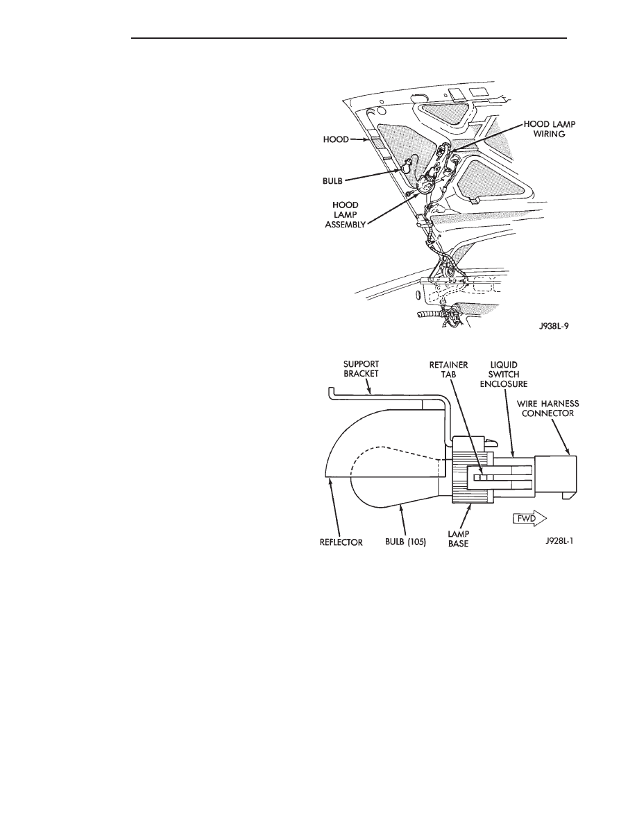
UNDERHOOD LAMP
When equipped, the underhood lamp is installed on
the hood right, rear panel. The lamp is on when hood
is opened by way of liquid ON/OFF switch that is
integral with lamp base (Fig. 13).
BULB REMOVAL
(1) Disconnect wire harness connector from under-
hood lamp (Fig. 12).
(2) Rotate bulb counterclockwise. Remove it from
lamp base socket.
BULB INSTALLATION
(1) Insert replacement bulb in lamp base socket.
Rotate it clockwise.
(2) Connect wire harness connector to lamp.
HOUSING REMOVAL
(1) Disconnect wire harness connector from lamp.
(2) Rotate bulb counterclockwise. Remove it from
lamp base socket.
(3) Remove screw that attaches lamp reflector
bracket to hood inner panel (Fig. 12).
(4) Remove lamp from hood inner panel.
HOUSING INSTALLATION
(1) Position underhood lamp on the hood inner
panel.
(2) Install screw through lamp and into the hood
panel.
(3) Insert bulb in lamp base socket and rotate it
clockwise.
(4) Connect wire harness connector to lamp.
Fig. 12 Underhood Lamp
Fig. 13 Underhood Lamp Components
8L - 8
LAMPS
Z
INTERIOR LAMPS
INDEX
page
page
Cargo Lamp/Bulb
. . . . . . . . . . . . . . . . . . . . . . . . . 10
Dome Lamp Bulb
. . . . . . . . . . . . . . . . . . . . . . . . . 10
Dome/Courtesy Lamp Service Information
. . . . . . . 9
Dome/Courtesy Lamp Trouble Diagnosis
. . . . . . . . 9
Dome/Reading Lamp
. . . . . . . . . . . . . . . . . . . . . . 10
Door Courtesy Lamp
. . . . . . . . . . . . . . . . . . . . . . 10
Illuminated Entry System Service Information
. . . . 11
Lighted Vanity Mirror
. . . . . . . . . . . . . . . . . . . . . . . 9
Lighted Vanity Mirror Trouble Diagnosis
. . . . . . . . . 9
Overhead Console
. . . . . . . . . . . . . . . . . . . . . . . . 11
Under Panel Lamp
. . . . . . . . . . . . . . . . . . . . . . . . 11
DOME/COURTESY LAMP SERVICE INFORMATION
The interior lamp bulbs illuminate when they are
connected to vehicle body ground. By way of appli-
cable switch:
• Dome lamp switch
• Glove box switch
• Door pillar switch
• Liftgate switch (if the cargo lamp is ON.)
If equipped with Security Alarm Module, refer to
Group 8Q—Vehicle Theft Security System.
DOME/COURTESY LAMP TROUBLE DIAGNOSIS
ALL LAMPS INOPERATIVE
(1) Slide the I/P illumination rheostat to the right.
The lamps should light. If not, remove, inspect and
test the dome lamp fuse.
(2) If fuse is OK, repair open circuit in the wire
harness to vehicle body ground.
(3) Replace left hand pod switch if dome lamp
switch fails.
ONE LAMP INOPERATIVE
(1) Measure the resistance across the bulb holder
terminals. The ohmmeter should indicate approxi-
mately zero ohms. If not, replace bulb.
(2) Measure voltage between voltage side of the
bulb holder and vehicle body ground. The voltmeter
should indicate battery voltage. If not, repair the open
circuit in the wire harness to the splice.
LAMPS INOPERATIVE WITH ONE OR MORE
DOORS OPENED
(1) Remove the faulty switch from the door pillar
and connect switch wire directly to ground. The lamp
should light.
(2) If not, check for an open circuit in ground wire.
Repair as necessary. If lamps still do not light, replace
switch.
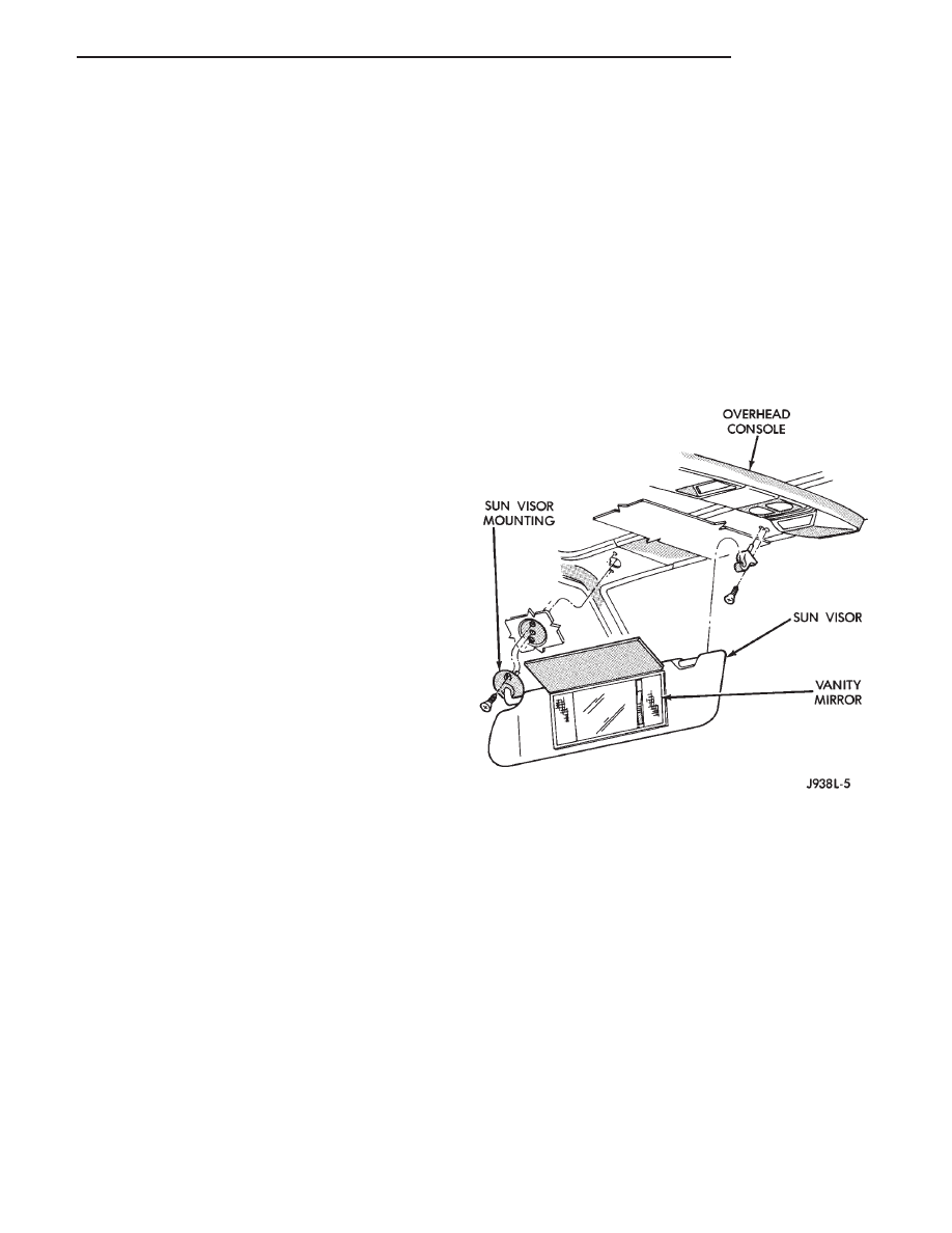
LIGHTED VANITY MIRROR
SERVICE INFORMATION
Both the driver and the front passenger sunvisor
can be equipped with a lighted vanity mirror. A lamp
is located at each side of the vanity mirror. The lamps
are switched ON automatically when the mirror cover
is lifted (Fig. 1).
Voltage is applied directly to the vanity lamp bulbs
by way of the dome lamp fuse.
LIGHTED VANITY MIRROR TROUBLE DIAGNOSIS
VANITY LAMPS INOPERATIVE
(1) Remove, inspect and test dome lamp fuse. Re-
place if defective.
(2) Test dome lamp operation. If OK, go to next
step. If not OK, repair the open circuit in the wire
harness from the splice.
(3) Measure the voltage between the pink wire on
switch connector and vehicle body ground. The volt-
meter should indicate battery voltage. If not OK,
repair the open circuit in wire harness from splice.
(4) Connect a jumper wire from the ground side of
the switch to a good vehicle body ground. Measure
the resistance to vehicle body ground. The ohmmeter
Fig. 1 Lighted Vanity Mirror
Z
LAMPS
8L - 9
should indicate approximately zero ohms. If not, re-
pair the open circuit in the wire harness to vehicle
body ground.
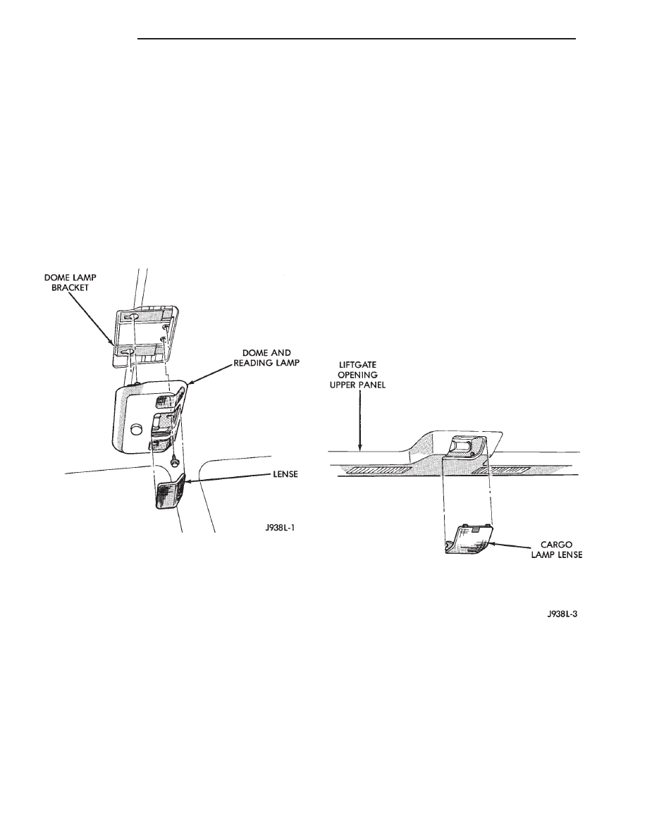
DOME/READING LAMP
REMOVAL
(1) Insert a flat blade screwdriver in slot at the
center of the lamp housing. Rotate screwdriver up-
ward and unsnap dome lamp lens.
(2) Pull lens downward. Remove it from lamp hous-
ing.
(3) Remove the lamp housing retaining screws (Fig.
2).
(4) Push housing forward and release housing from
bracket.
(5) Disconnect wire harness connectors.
(6) Remove lamp housing from headliner cavity.
INSTALLATION
(1) Position dome/reading lamp housing at head-
liner cavity.
(2) Connect wire harness connectors.
(3) Locate rear pods of the lamp in the slots of the
dome lamp bracket. Push lamp housing up and to
rear.
(4) Install the lamp housing screws (Fig. 2).
(5) Position dome lamp lens at lamp housing. Snap
lens into housing.
DOME LAMP BULB
REMOVAL
(1) Insert a flat blade screwdriver in slot at front of
lens.
(2) Rotate the screwdriver until lens snaps out of
the housing.
(3) Remove lens from housing.
(4) Remove bulb from terminals.
INSTALLATION
(1) Insert bulb into reding lamp terminals.
(2) Replace lens by holding lens level and pushing
rearward into housing.
(3) Push lens up to snap into housing.
CARGO LAMP/BULB
The cargo lamp bulb housing is integral with the
upper rear headliner trim moulding. To replace bulb
housing the trim moulding must be replaced.
REMOVAL
(1) Insert a flat blade screwdriver in slots provided
at lower portion of lens.
(2) Rotate screwdriver upward until lens snaps out
of housing.
(3) Remove lens from housing (Fig. 3).
(4) Remove bulb from bulb holder.
INSTALLATION
(1) Install bulb in holder.
(2) Insert upper tabs of lens into lens housing.
(3) Snap lower portion of lens into slots at lens
housing (Fig. 3).
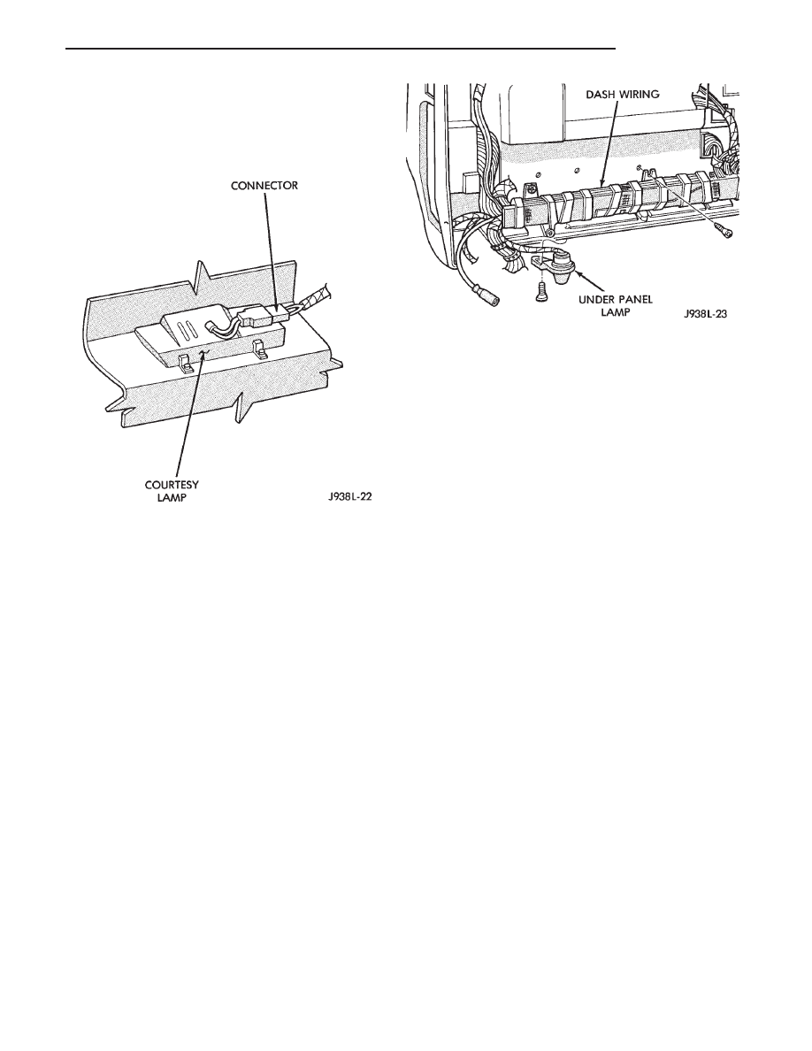
DOOR COURTESY LAMP
REMOVAL
(1) Remove door panel. Refer to Group 23—Body
Components for service procedure.
(2) Disconnect wiring harness connector (Fig. 4).
Fig. 2 Dome/Reading Lamp
Fig. 3 Cargo Lamp
8L - 10
LAMPS
Z
(3) Carefully insert a thin flat blade screwdriver
between lens and door trim panel.
(4) Rotate screwdriver to remove lens.
(5) Push door courtesy lamp housing through door
trim panel.
INSTALLATION
(1) Connect wiring harness.
(2) Insert door courtesy lamp into door trim panel.
(3) Install door trim panel.
UNDER PANEL LAMP
REMOVAL
(1) Remove 1 mounting screw (Fig. 5).
(2) Disconnect wiring harness connector.
INSTALLATION
For installation, reverse removal procedure.
OVERHEAD CONSOLE
To remove or repair overhead console refer to Group
8C, Overhead Console.
ILLUMINATED ENTRY SYSTEM SERVICE INFOR-
MATION
The Illuminated Entry System is activated by the
system relay. The relay is located in the relay center
behind instrument panel. The relay receives input
from door pillar switches, the keyless entry system,
and the ignition switch (when in the RUN position).
When input is received, the timer in the relay imme-
diately begins the timing-out process. The timing-out
process requires approximately 30 seconds. Interior
lamps are turned off either when the 30 second time-
out is completed or when the ignition switch is turned
ON. If a door remains open for more than 30 seconds,
the interior lamps will stay on until the door is closed.
The illuminated entry system also operates
when a door is opened to exit vehicle. When
door is closed the lamps will stay on for remain-
ing portion of the 30 seconds.
ILLUMINATED ENTRY RELAY
To remove or replace relay, refer to Auto Headlamp
Module procedure located in this section.
Fig. 4 Door Courtesy Lamp
Fig. 5 Under Panel Lamp—Rear View
Z
LAMPS
8L - 11
EXTERIOR LAMP SYSTEMS
INDEX
page
page
Auto Headlamps
. . . . . . . . . . . . . . . . . . . . . . . . . 12
Daytime Running Light Module
. . . . . . . . . . . . . . . 12
Lamp Outage Module
. . . . . . . . . . . . . . . . . . . . . . 16
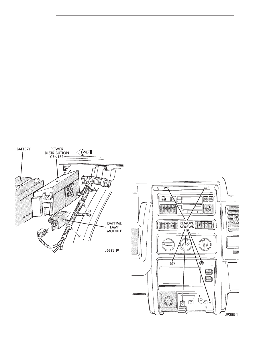
DAYTIME RUNNING LIGHT MODULE
The headlamps on vehicles sold in Canada, will go
ON when the ignition is turned ON. The module must
also receive a movement signal from distance sensor.
This provides a constant Lights On condition while
the vehicle is rolling. The lamps illuminate at less
than 50% of normal intensity.
The Daytime Running Light Module is located on
right inner fender below power distribution center.
(1) Remove bolts holding module and bracket to
vehicle (Fig. 1).
(2) Disconnect electrical connector.
To install module, reverse the removal procedures.
AUTO HEADLAMPS
This system automatically turns the lamps on and off
according to light conditions. The system also keeps the
lights on for a selected amount of time after driver has
parked and left vehicle. The system can be turned off to
give driver manual control of headlamps.
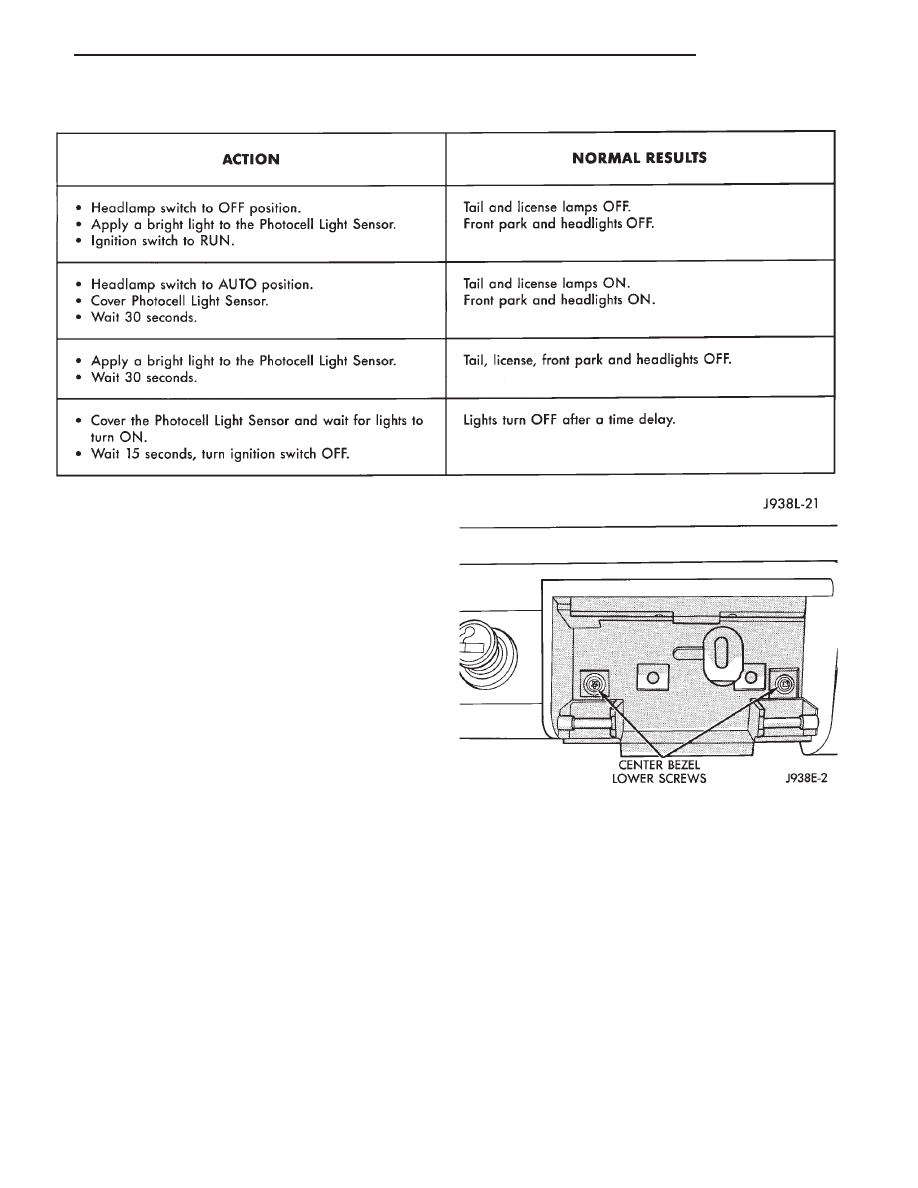
AUTO HEADLAMP SYSTEM DIAGNOSIS
Perform the system check in the order shown. When a
fault is found, refer to the Body Diagnostic Manual. If a
normal result is found at each and every step of the
System Check, the fault may be intermittent.
To find an intermittent fault, check the mating
terminals at each component and connector for a poor
connection. Also check that each terminal of mating
connectors is properly seated. If the connections ap-
pear to be reliable, try the System Check again while
moving the wire harness from side to side at each
component. Once a fault has been corrected, perform
the System Check to verify the diagnosis.
AUTO HEADLAMP MODULE
The module receives inputs from the auto headlamp
switch and auto headlamp sensor. Based on these
inputs the module will control the lamps. The auto
headlamp module is located behind the glove box to
the right of the security alarm module.
REMOVAL
(1) Disconnect battery negative cable.
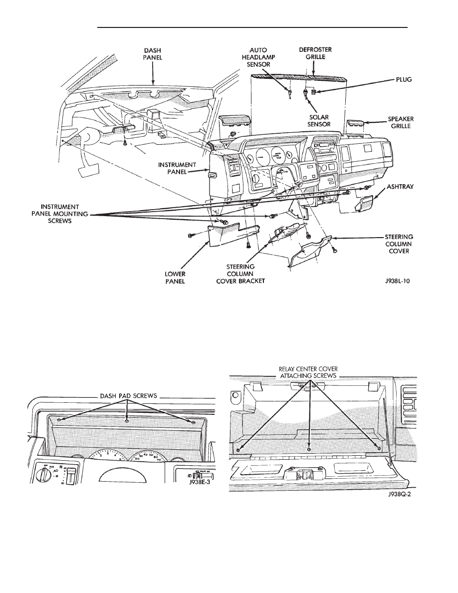
(2) Remove two screws holding top of center cluster
bezel (Fig. 2).
Fig. 2 Center Bezel Upper Screws
Fig. 1 Daytime Running Light Module
8L - 12
LAMPS
Z
(3) Remove ash tray.
(4) Remove two screws holding center of bezel.
(5) Remove two screws holding bottom of bezel (Fig.
3).
(6) Remove center bezel.
(7) Remove two screws holding dash pad located
behind center bezel.
Fig. 3 Center Bezel Lower Screws
AUTO HEADLAMP SYSTEM CHECK
Z
LAMPS
8L - 13
(8) Gently pry defroster bezel out of dash pad (Fig.
4).
(9) Unplug sensor(s) and set defroster bezel aside.
(10) Remove screws in defroster duct opening hold-
ing dash pad.
(11) Remove speaker grilles. Remove screws behind
speaker grilles.
(12) Remove three screws above IP cluster holding
dash pad (Fig. 5).
(13) Open glove box and remove 2 screws holding
dash pad.
(14) Pull up on dash pad to unsnap clips and then
remove dash pad.
(15) Remove four screws holding glove box bottom
(Fig. 6).
Fig. 4 Instrument Panel
Fig. 5 Dash Pad Screws
Fig. 6 Glove Box
8L - 14
LAMPS
Z
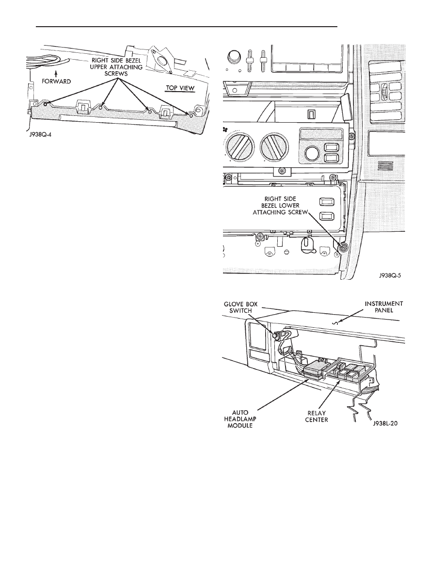
(16) Remove four screws from top of glove box bezel
(Fig. 7).
(17) Remove one screw holding the bezel to the
center armature (Fig. 8).
(18) Remove bezel from instrument panel. Discon-
nect glove box light switch.
(19) Remove 2 screws holding auto headlamp mod-
ule (Fig. 9).
(20) Remove connector from module.
For installation, reverse removal procedure.
AUTO HEADLAMP SENSOR
The auto headlamp sensor is the key sensor for the
auto headlamp system. The module utilizes the sen-
sor input to determine when to turn the headlamps
on or off. The sensor is located in the center of the
defroster grille at the base of the windshield.
Fig. 7 Right Side Bezel
Fig. 8 Right Side Lower Screw
Fig. 9 Auto Headlamp Module
Z
LAMPS
8L - 15
REMOVAL (FIG. 10)
(1) Gently pry defroster bezel out of dash pad.
(2) Unplug auto headlamp sensor connector.
(3) Snap out sensor from bezel.
For installation, reverse the removal procedure.
LAMP OUTAGE MODULE
Details for the lamp outage module can be found in
Group 8E, Vehicle Information Center. For circuit
location refer to the Wiring Diagrams.
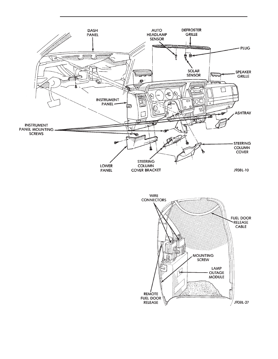
REMOVAL
(1) Remove battery negative cable.
(2) Remove spare tire from carrier.
(3) Remove access door (Fig. 11).
(4) Remove wiring connectors at top of module.
(5) Remove 1 screw holding module to inner quar-
ter panel.
(6) Remove lamp outage module.
For installation, reverse the removal procedure.
Fig. 10 Instrument Panel
Fig. 11 Lamp Outage Module
8L - 16
LAMPS
Z

BULB APPLICATION
GENERAL INFORMATION
The following Bulb Application Table lists the lamp
title on the left side of the column and trade number
or part number on the right.
CAUTION: Do not use bulbs that have a higher
candle power than bulb listed in the Bulb Applica-
tion Table. Damage to lamp can result. Do not touch
halogen bulbs with fingers or other oily surfaces.
Bulb life will be reduced.
EXTERIOR LAMPS
Back-up .................................................................1156
Center High Mounted Stop Lamp ........................921
Fog............................................................................H3
Front Turn Signal ...........................................1295NA
Front Side Marker ............................................194NA
Headlamp/Aero ..................................................H6054
License Plate ..........................................................168
Rear/Stop/Tail .......................................................2057
Rear Turn Signal ..................................................1156
Underhood Lamp....................................................105
INTERIOR LAMPS
Service procedures for most of the lamps in the
instrument panel, are located in Group 8E. Some
components have lamps that can only be serviced by
an Authorized Service Center (ASC) after the compo-
nent is removed from the vehicle. Contact local dealer
for location of nearest ASC.
Ash Receiver .........................................................1891
Cargo Lamp .........................................................212-2
Cigarette Lighter......................................................53
Climate Control ........................................................74
Console Floor Shifter ........................................PC194
Dome/Reading ..........................................561 and 906
Door Courtesy.........................................................168
Glove Compartment ..........................................PC194
Overhead Console ...............................................212-2
Radio ......................................................................ASC
Rocker Switch...........................................................37
Transfer Case Shifter........................................PC194
Under Panel Courtesy .............................................89
*Vanity Mirror..........................................P/N6501966
*Available only at Chrysler Dealers.
Z
LAMPS
8L - 17

Document Outline
- LAMPS
- GENERAL INFORMATION
- DIAGNOSTIC PROCEDURES
- SERVICE PROCEDURES
- HEADLAMP ALIGNMENT
- HEADLAMP ALIGNMENT PREPARATION
- HEADLAMP/ FOG LAMP ADJUSTMENT USING ALIGNMENT SCREEN
- AERO HEADLAMP REPLACEMENT
- PARKING LAMP BULB/ LENS REPLACEMENT
- TURN SIGNAL AND SIDE MARKER LAMP
- FOG LAMPS
- HEADLAMP SWITCH
- TURN SIGNAL/ DIMMER SWITCH
- FOG LAMP SWITCH REPLACEMENT
- TAIL AND STOP LAMPS
- BACKUP LAMPS
- TURN SIGNAL LAMP
- REAR SIDE MARKER LAMP
- LICENSE PLATE LAMP
- CENTER HIGH MOUNTED STOP LAMP (CHMSL)
- UNDERHOOD LAMP
- INTERIOR LAMPS
- EXTERIOR LAMP SYSTEMS
- BULB APPLICATION
Wyszukiwarka
Podobne podstrony:
93ZJ Secc 11 Exhaust System and Intake Manifold
93ZJ Secc 8J Turn Signals and Hazard Warning Flashes
93ZJ Secc 8F Audio Systems
93ZJ Secc 8R Power Seats
93ZJ Secc 16 Propeller Shafts
93ZJ Secc 6 Clutch
93ZJ Secc 8B Battery Starter Motor Generator Service
93ZJ Secc 8A Electrical Systems
93ZJ Secc 8M Restraint Systems
93ZJ Secc 22 Wheels and Tires
93ZJ Secc 25 Emission Control Systems
93ZJ Secc 0 Lubrication and Maintenance
93ZJ Secc 8G Horns
96ZJ 8L LAMPS
93ZJ Secc 8Q Vehicle Theft Security System
93ZJ Secc 8T Power Mirrors
93ZJ Secc 8K Windshield Wiper and Washer Systems
93ZJ Secc 8C Overhead Console
93ZJ Secc 8U Chime Buzzer Warning Systems
więcej podobnych podstron