OVERHEAD CONSOLE
CONTENTS
page
page
COMPASS REPAIR PROCEDURES
. . . . . . . . . . . 6
CONSOLE REPAIR PROCEDURES
. . . . . . . . . . . 8
DESCRIPTION
. . . . . . . . . . . . . . . . . . . . . . . . . . . 1
DIAGNOSTIC PROCEDURES
. . . . . . . . . . . . . . . . 2
KEYLESS ENTRY RECEIVER . . . . . . . . . . . . . . . . 9
LENS/LAMP REPLACEMENT
. . . . . . . . . . . . . . . 9
PUSH BUTTON MODULE REPLACEMENT
. . . . . 8
THERMOMETER SENSOR REPLACEMENT . . . . . 8
TRIP COMPUTER REPLACEMENT
. . . . . . . . . . . 8
DESCRIPTION
The overhead console includes:
• reading and courtesy lights for the front and rear
seats
• the receiver for the keyless entry system
• storage compartment for remote garage door
opener
• storage compartments sun glasses.
A compass/thermometer mini trip computer that
displays 6 conditions:
• Compass/Temperature
• Trip odometer (ODO)
• Average miles per gallon (ECO)
• Instant miles per gallon (ECO)
• Distance to empty (DTE)
• Elapsed time (ET)
• Blank Display
READING AND COURTESY LAMPS
All reading and courtesy lamps in the overhead
console are activated by the door courtesy circuit.
When all four doors and the liftgate are closed the
lamps can be activated by depressing the correspond-
ing lens. When any door or the liftgate is open, the
switches are disabled. They will not turn the lamps
off.
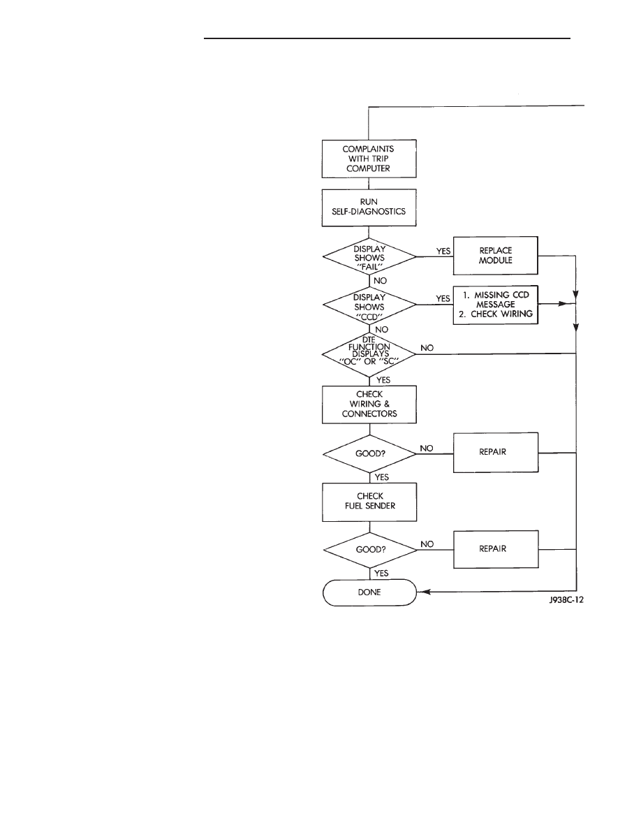
TRIP COMPUTER
Actuating the STEP switch will cause the trip com-
puter to change mode of operation when ignition is
ON. Traveler data is obtained from the Powertrain
Control Module and HEVAC on the CCD lines. If the
data displayed is wrong, run self diagnostics before
replacing the computer. The DRB II is recommended
for checking the CCD lines.
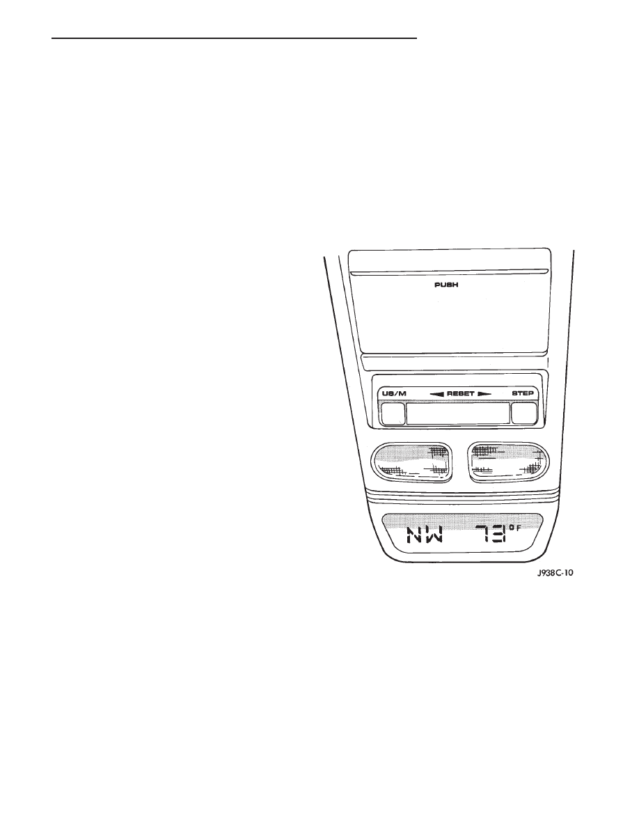
COMPASS
The compass will display the direction the vehicle is
pointed in using the 8 major compass headings (Ex-
amples: North is ‘‘N’’, Northeast is ‘‘NE’’). It does not
display the headings in actual degrees.
The compass is a self calibrating unit that requires
no adjusting. The only calibration that may prove
necessary is to drive the vehicle in 3 complete circles,
on level ground, in not less than 48 seconds. This will
‘‘reorient’’ the unit to its vehicle. The unit will also
compensate for magnetism the vehicle may acquire
during its life. Care should be used to avoid putting
anything magnetic on the roof of the vehicle.
The unit can compensate for some magnetic fields
in the body. The use of magnetic attachments like
antenna mounts or repair order ‘‘hats’’ placed directly
on the roof can exceed the compensation ability of the
unit. Magnetic bit drivers used on the fasteners to
hold the assembly to the roof header can also affect
operation. If the vehicle roof should become magne-
tized, then the demagnetizing and calibration proce-
dures may be required to restore proper operation.
Z
OVERHEAD CONSOLE
8C - 1
If the front console attaching screw is re-
placed, the new screw must be a #10 stainless.
If the compass functions but accuracy is suspect, it
may be necessary to perform a variation adjustment.
This procedure allows the unit to accommodate varia-
tions in the earth’s magnetic field strength based on
geographic location.
If the compass has blanked out and only CAL
appears, demagnetizing may be necessary to re-
move residual magnetic fields.
THERMOMETER
The ambient temperature display can be changed
from Fahrenheit to Celsius using the US/Metric but-
ton. The temperature reported is not an instant read-
ing of conditions but an average temperature. It may
take the unit several minutes to react to a major
change such as driving out of a heated garage into
winter temperatures.
When the ignition switch is turned off, the last
displayed temperature reading stays in memory.
If the temperature is more than 55°C (131°F) or the
circuit is shorted to ground, the temperature display
should read SC. If the temperature message received
is less than -40°C (-40°F), or an open circuit exists,
the display should read OC.
DIAGNOSTIC PROCEDURES
Follow the appropriate diagnostic flow chart:
• Chart 1 Describes the procedures for compass and
display problems.
• Chart 2 Describes the procedures for outside tem-
perature measuring problems.
• Chart 3 Describes the procedures for illumination
lamp problems.
Chart 1
8C - 2
OVERHEAD CONSOLE
Z
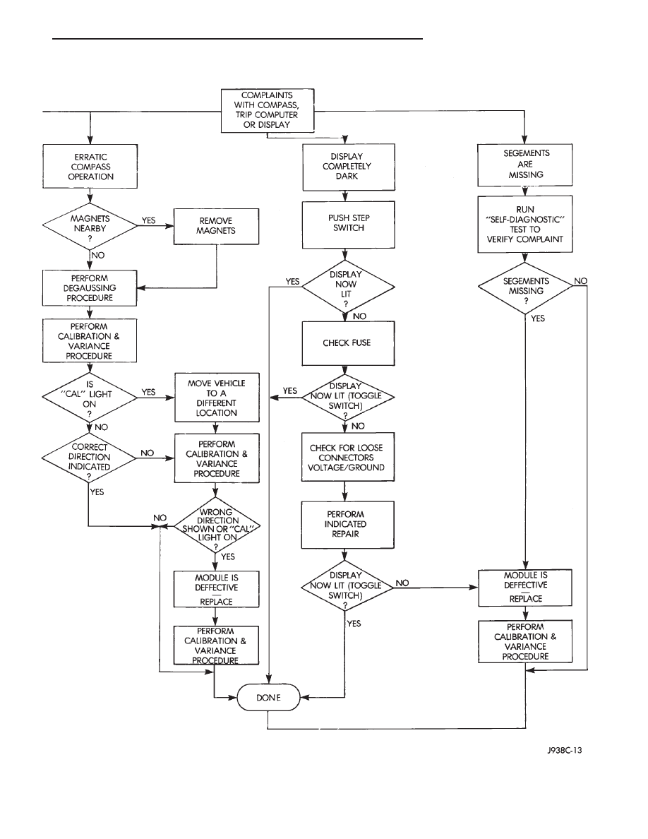
Chart 1 Continued
Z
OVERHEAD CONSOLE
8C - 3
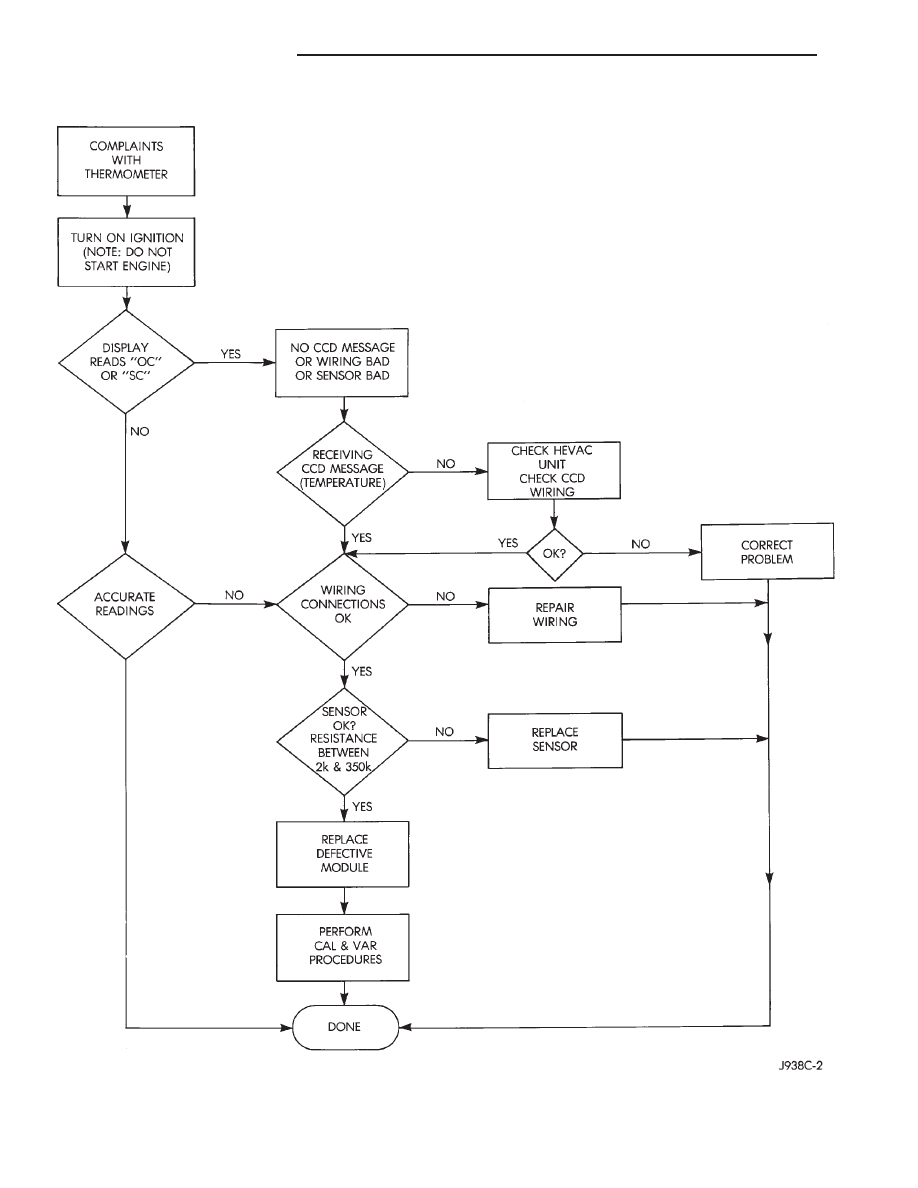
Chart 2
8C - 4
OVERHEAD CONSOLE
Z
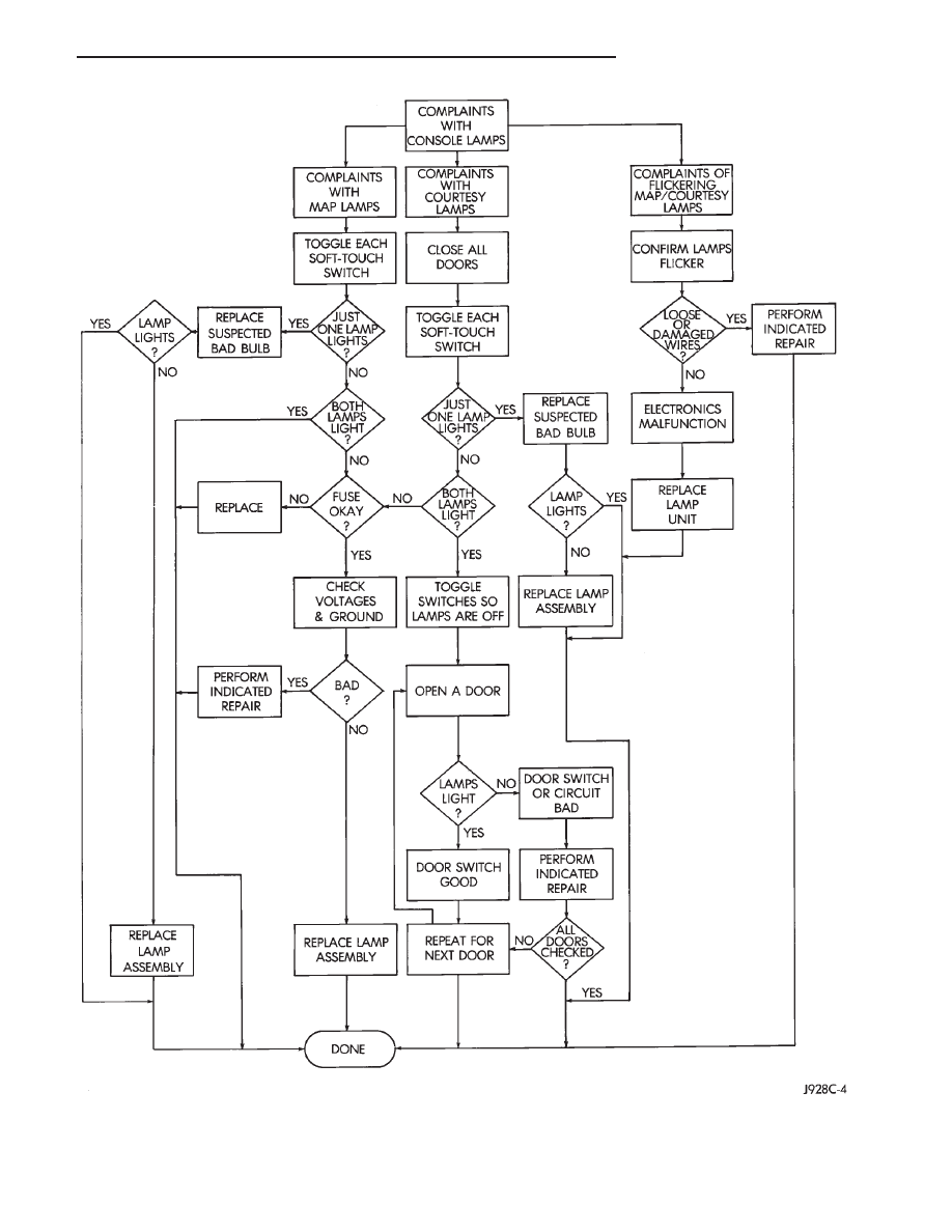
Chart 3
Z
OVERHEAD CONSOLE
8C - 5
COMPASS REPAIR PROCEDURES
VARIATION ADJUSTMENT PROCEDURE
Variance is the difference between magnetic North
and geographic North. In some areas the difference
between magnetic and geographic north is great
enough to cause the compass to give false readings. If
this occurs, the variance must be set.
To set the variance: turn key to the ON position.
Depress both buttons and hold down until VAR light
appears. This takes about 5 seconds.
Release both buttons.
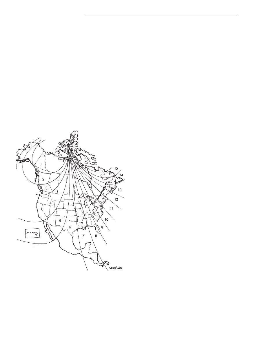
Using the map (Fig. 1) find your geographic location
and note the Zone Number.
Press the U.S./Metric button to sequentially go
through the numbers until the zone number for your
area appears in the display.
Press the STEP button to enter this zone number.
Confirm correct directions are indicated.
COMPASS CALIBRATION PROCEDURE
CAUTION: DO NOT use magnetic tools when servic-
ing the overhead console.
CAUTION: DO NOT place any external magnets such
as magnetic roof mount antennas, in the vicinity of
the compass.
Do not attempt to set compass near large metal
objects such as other vehicles, large buildings or
bridges. The compass features an ‘‘Auto-Cal’’ design
which simplifies the calibration procedure. During
normal driving this feature automatically updates the
compass calibration. This takes into account small
changes in magnetism the vehicle may see over its
life time.
Calibrate the compass manually as follows:
(1) Start the engine.
(2) Depress both buttons and hold down until CAL
light appears. This takes about 10 seconds and ap-
pears about 5 seconds after the VAR light appears.
(3) Release buttons.
(4) Drive vehicle on a level surface that is away
from metal objects through 3 or more complete
circles, in not less than 48 seconds. The CAL light
will go off and the compass is now calibrated.
If CAL light does not go off, either there is
excessive magnetism near the compass or the
unit is defective. Repeat the demagnetizing and
calibration procedures at least one more time.
If the wrong direction is still indicated, the
area selected may be too close to a magnetic
source. Repeat the calibration procedure in an-
other location.
DEMAGNETIZING PROCEDURE
The tool used to demagnetize the forward console
attaching screw and roof panel is the Miller Tool
6029. Equivalent units must be rated as continuous
duty for 110/115 volts and 60Hz. They must also have
a field strength of over 350 gauss at 1/4 inch beyond
the tip of the probe.
In this procedure the demagnetizing tool is used to
demagnetize both the roof panel and console forward
mounting screw.
(1) Be sure the ignition switch is in the OFF posi-
tion before you begin the demagnetizing procedures.
(2) Plug the demagnetizing tool into a 110/115 volt
outlet while keeping the tool at least 2 inches away
from the compass area.
CONSOLE FORWARD MOUNTING SCREW
(3) Slowly approach the head of the forward mount-
ing screw with the plastic coated tip of the demagne-
tizing tool. Contact the head of the screw for about 2
seconds.
(4) With the demagnetizing tool still energized,
slowly back it away from the screw until the tool is at
least 2 inches from the screw head. Unplug the tool.
ROOF PANEL
(5) Place an 8 1/2 X 11 piece of paper on the center
of the roof at the windshield, oriented lengthwise
from front to rear. The purpose of the paper is to
protect the roof panel from scratches and define the
area
Fig. 1 Variance Settings
8C - 6
OVERHEAD CONSOLE
Z
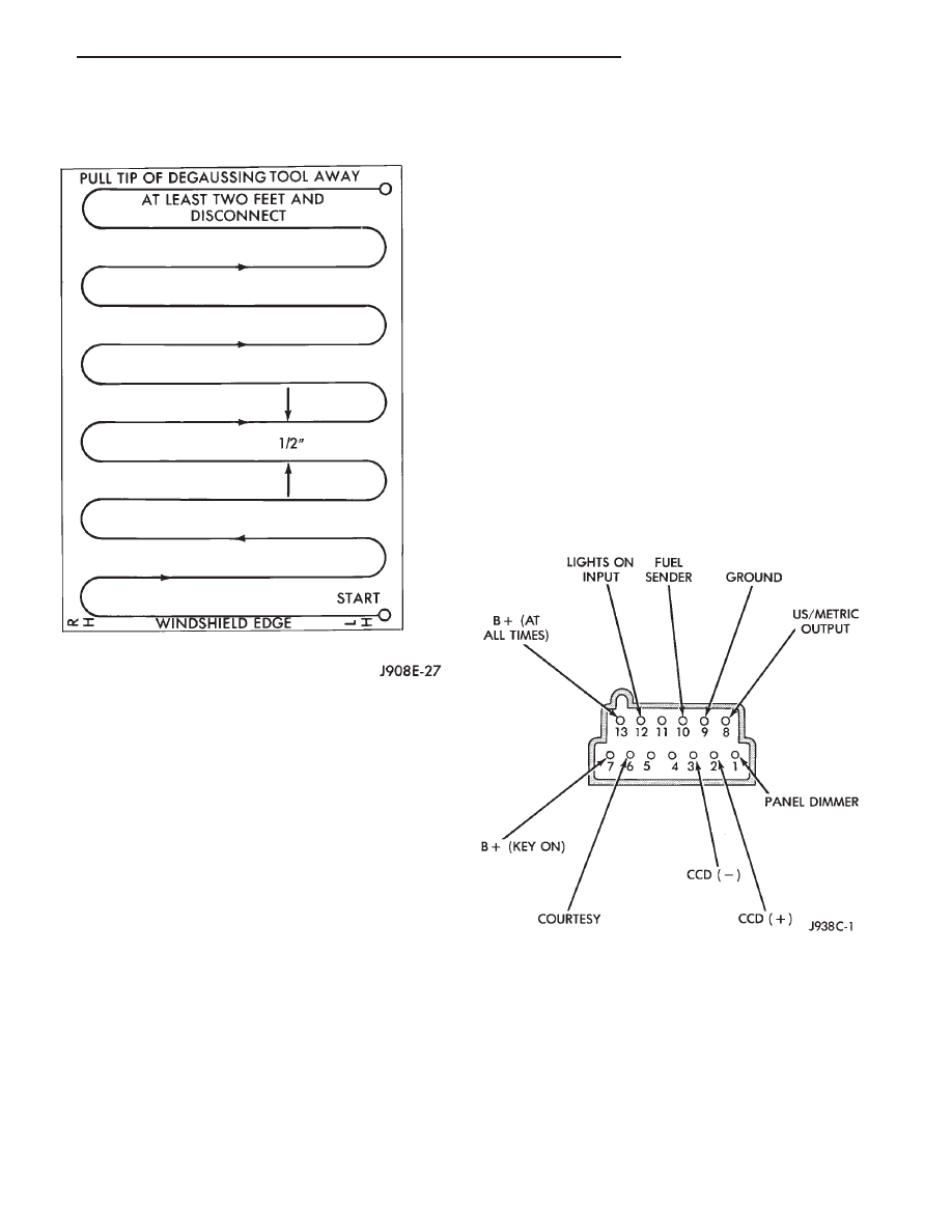
to be degaussed (Fig. 2). Figure 2 shows the recom-
mended sweep pattern of 1/2 inch between passes in a
sweeping zig-zag pattern.
(6) Plug in the demagnetizing tool. Keep the tool at
least 2 inches away from the compass unit.
(7) Slowly approach the center of the roof panel at
the windshield with the demagnetizing tool plugged
in.
(8) Contact the roof panel with the tip of the tool
(be sure template is in place to avoid scratching the
roof panel). Use slow sweeping motions of 1/2 inch
between sweeps. Move the tool approximately 4
inches either side of the centerline and at least 11
inches back from the windshield.
(9) With the demagnetizing tool still energized,
slowly back it away from the roof panel until the tip
is at least 2 inches from the roof. Unplug the tool.
(10) Calibrate the compass and set the variance as
described.
SELF-DIAGNOSTIC TEST
The Self-Diagnostic test is used to verify compass
electrical operation and that all CCD messages re-
quired are being received. This can be used to confirm
that the display and all of its segments are operating
properly. Initiate the self-diagnostic test as follows:
(1) With the ignition switch in the OFF position
simultaneously press and hold the STEP button and
the US/METRIC button.
(2) Turn ignition switch to ON.
(3) Continue to hold both buttons until all seg-
ments on the display light. The module is now in self
diagnostic test. The test will:
(a) Display all segments
(b) Check internal circuitry
(c) Check if all CCD messages needed are being
received.
(4) If tests (a) and (b) pass, the module will auto-
matically return to normal operation.
(5) If test (b) fails, the module will display ‘‘FAIL’’.
To return to normal operation press either button.
Replace module.
(6) If test (c) fails, the module is not receiving all
the CCD messages required for operation. The failure
message on the display will be ‘‘CCD’’. Check CCD
buss for missing messages. Press either button to
return to normal operation.
Should any segment in any of the digit posi-
tions fail to light, the unit is defective and
should be replaced.
Fig. 2 Roof Demagnetizing Pattern
Fig. 3 Compass/Temperature Harness Connector
Z
OVERHEAD CONSOLE
8C - 7
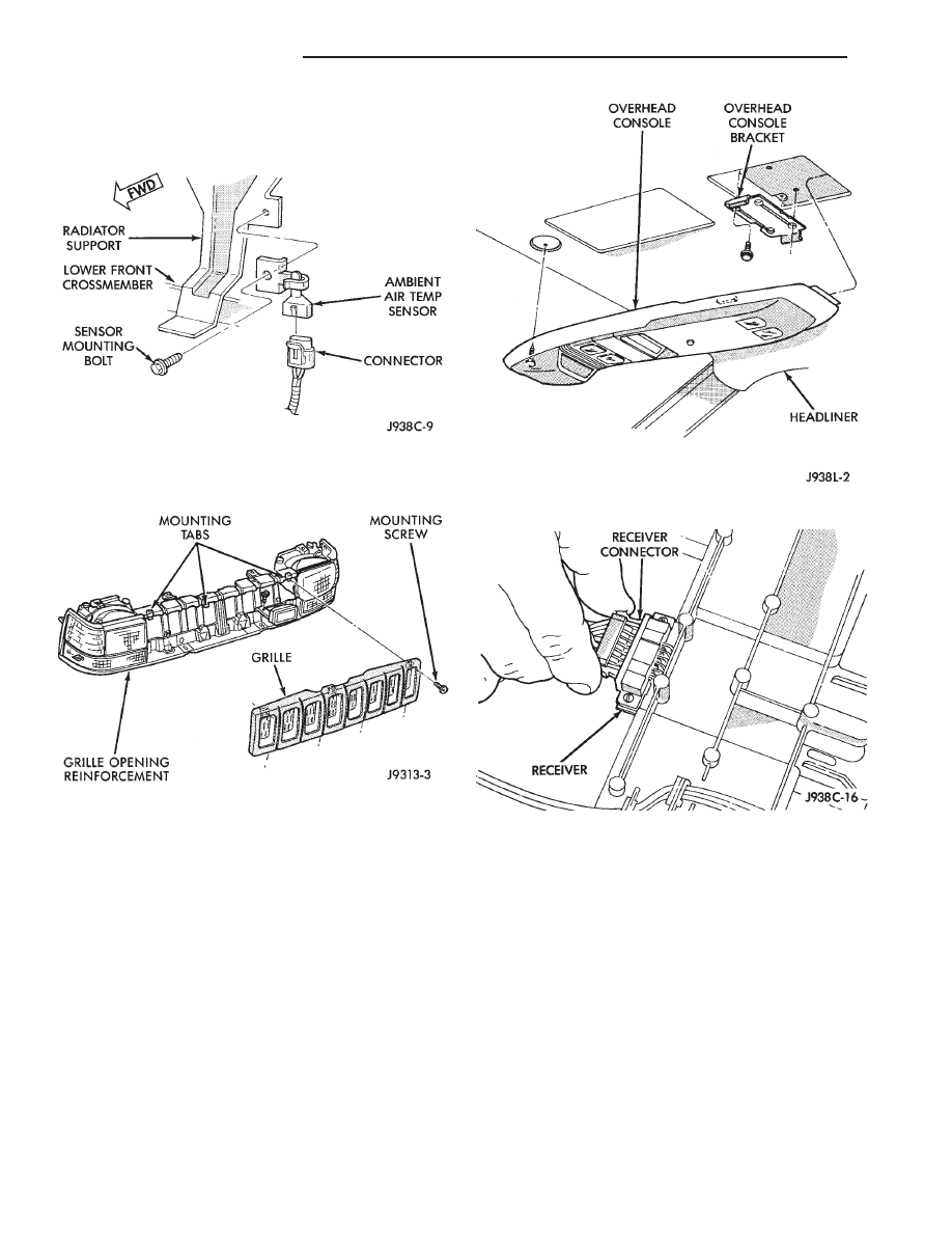
THERMOMETER SENSOR REPLACEMENT
The sensor is mounted to the radiator support in
the center just behind the grille (Fig. 1).
Remove the grille to access the sensor (Fig. 2).
CONSOLE REPAIR PROCEDURES
(1) Remove console forward mounting screw (Fig.
3).
(2) Slide console forward until the console detaches
from the rear mounting bracket.
(3) Disconnect wire harnesses from keyless entry
and compass (Fig. 4).
(4) To install overhead console, reverse the removal
procedures.
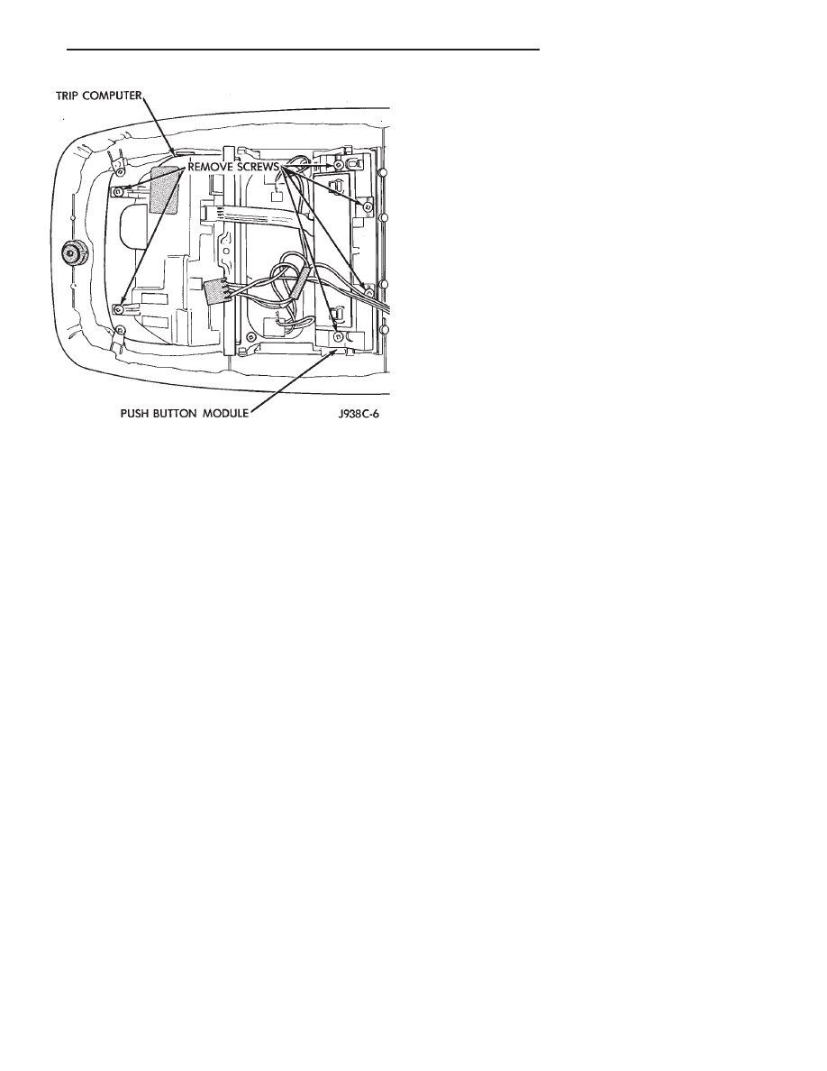
TRIP COMPUTER REPLACEMENT
(1) Remove overhead console and disconnect wir-
ing. Refer to Console Repair Procedures.
(2) Unplug harness connectors from Trip Computer.
(3) Remove 2 screws holding trip computer to con-
sole (Fig. 5).
(4) Spread retaining tabs on the sides to remove
trip computer from the console.
(5) For installation, reverse the removal proce-
dures.
PUSH BUTTON MODULE REPLACEMENT
(1) Remove overhead console and disconnect wir-
ing. Refer to Console Repair Procedures.
(2) Unplug harness connectors from Push Button
Module.
(3) Remove 4 screws holding module to console
(Fig. 5).
(4) Remove module from console.
(5) For installation, reverse the removal proce-
dures.
Fig. 1 Ambient Temperature Sensor.
Fig. 2 Grille Removal
Fig. 3 Remove/Install Overhead Console
Fig. 4 Keyless Entry Harness Connector
8C - 8
OVERHEAD CONSOLE
Z
LENS/LAMP REPLACEMENT
(1) Insert a long flat blade tool at the notch on the
curved edge of the lens. Carefully pry the lens from
the housing and pivot the lens down. It may be neces-
sary to move the tool along the edge to free the lens.
(2) Remove bulb by pulling straight down.
(3) Install new bulb by pushing firmly into socket.
(4) Pivot lens up into position and snap in. Test by
pressing lens for proper operation and lighting.
KEYLESS ENTRY RECEIVER
Refer to Group 8P - Power Locks.
Fig. 5 Trip Computer Removal/Installation
Z
OVERHEAD CONSOLE
8C - 9

Document Outline
- OVERHEAD CONSOLE
Wyszukiwarka
Podobne podstrony:
93ZJ Secc 11 Exhaust System and Intake Manifold
93ZJ Secc 8J Turn Signals and Hazard Warning Flashes
93ZJ Secc 8F Audio Systems
93ZJ Secc 8R Power Seats
93ZJ Secc 16 Propeller Shafts
93ZJ Secc 6 Clutch
93ZJ Secc 8L Lamps
93ZJ Secc 8B Battery Starter Motor Generator Service
93ZJ Secc 8A Electrical Systems
93ZJ Secc 8M Restraint Systems
93ZJ Secc 22 Wheels and Tires
93ZJ Secc 25 Emission Control Systems
93ZJ Secc 0 Lubrication and Maintenance
93ZJ Secc 8G Horns
96ZJ 8V OVERHEAD CONSOLE SYSTEMS
93ZJ Secc 8Q Vehicle Theft Security System
93ZJ Secc 8T Power Mirrors
93ZJ Secc 8K Windshield Wiper and Washer Systems
93ZJ Secc 8U Chime Buzzer Warning Systems
więcej podobnych podstron