ELECTRICAL
GROUP INDEX
page
page
. . . . . . . . . . . . . . . . . . . . . . . 8F
BATTERY/STARTER/GENERATOR SERVICE
BATTERY/STARTING/CHARGING SYSTEMS
. . . . . . . . . . . . . . . . . . . . . . . . 8A
CHIME WARNING/REMINDER SYSTEM . . . . . . 8U
HORNS
. . . . . . . . . . . . . . . . . . . . . . . . . . . . . . . 8G
. . . . . . . . . . . . . . . . . . . . . 8D
. . . . . . . . . . . . . . . . . . . . . . . . . . . . . . . 8L
. . . . . . . . . . . . . . . . . . . 8C
POWER LOCKS . . . . . . . . . . . . . . . . . . . . . . . . . 8P
. . . . . . . . . . . . . . . . . . . . . . 8T
POWER WINDOWS . . . . . . . . . . . . . . . . . . . . . . 8S
POWER SEATS
. . . . . . . . . . . . . . . . . . . . . . . . . 8R
. . . . . . . . . . . . . . 8N
. . . . . . . . . . . . . . . . . . . . . . . . . . 8M
TURN SIGNALS AND HAZARD WARNING FLASHER
. . . . . . . . . . . . . . . . . . . . . . . . . . . . . . . . . . . . . . 8J
VEHICLE SPEED CONTROL SYSTEM . . . . . . . . 8H
VEHICLE THEFT SECURITY SYSTEM
WINDSHIELD WIPERS AND WASHERS . . . . . . 8K
WIRING DIAGRAMS
. . . . . . . . . . . . . . . . . . . . 8W
BATTERY/STARTING/CHARGING SYSTEMS DIAGNOSTICS
CONTENTS
page
page
BATTERY TEST PROCEDURES
. . . . . . . . . . . . . . 2
ENGINE STARTER MOTOR TEST
PROCEDURES
. . . . . . . . . . . . . . . . . . . . . . . . 10
GENERATOR TEST PROCEDURES ON
VEHICLE . . . . . . . . . . . . . . . . . . . . . . . . . . . . . 15
IGNITION OFF DRAW (IOD)
. . . . . . . . . . . . . . . . 9
SPECIFICATIONS
. . . . . . . . . . . . . . . . . . . . . . . 21
GENERAL INFORMATION
The Battery, Starting, and Charging Systems oper-
ate with one another, and therefore, must be thor-
oughly tested as a complete system. In order for the
vehicle to start and charge properly, it must have a
battery that will perform to specifications. The starter
motor, generator, wiring, and electronics also must
perform within specifications. Group 8A covers Start-
ing (Fig. 1) and Charging (Fig. 2) System diagnostic
procedures. These procedures include the most basic
conventional methods to On-Board Diagnostics (OBD)
built into the Powertrain Control Module (PCM). Use
of an ammeter, volt/ohmmeter, battery charger, car-
bon pile rheostat (load tester), and 12 volt test light
will be required.
All OBD sensing systems are monitored by the
PCM. The PCM will store in memory any detectable
failure in the monitored circuits. Refer to Using On-
Board Diagnostic System in this group for more infor-
mation.
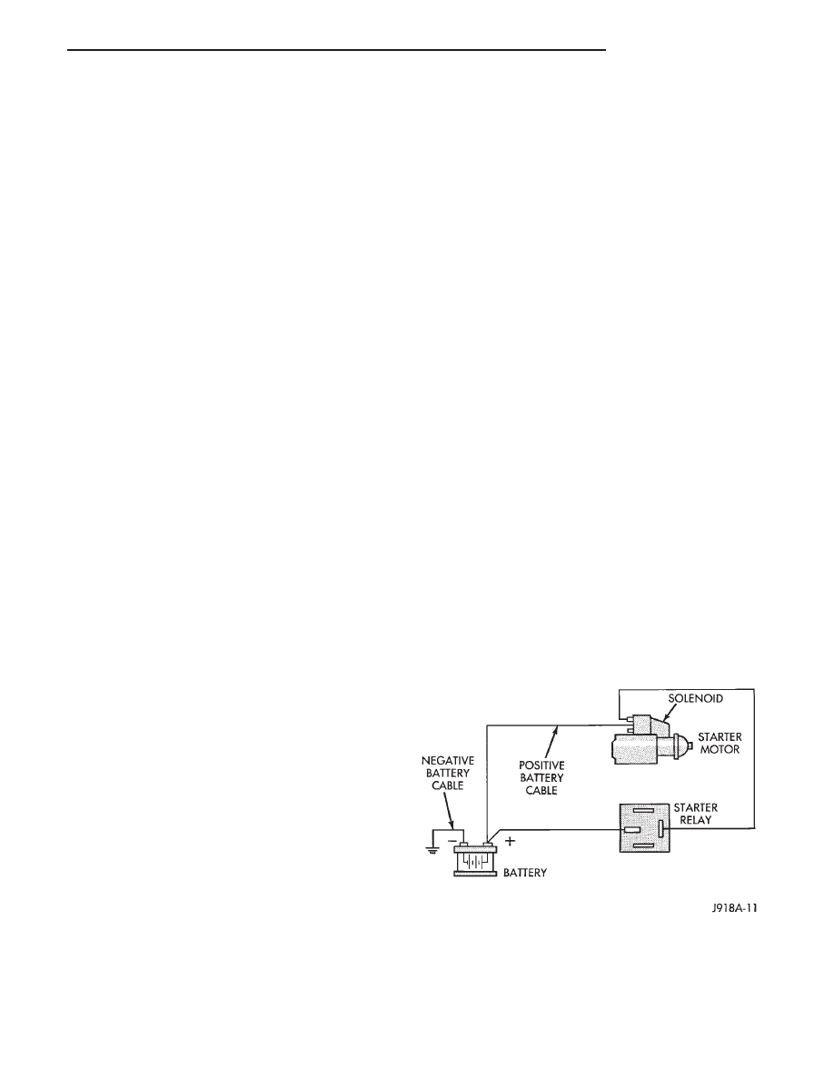
Fig. 1 Starting System Components (Typical)
Z
ELECTRICAL
8A - 1
BATTERY TEST PROCEDURES
INDEX
page
page
Abnormal Battery Discharging
. . . . . . . . . . . . . . . . 4
Battery Charging
. . . . . . . . . . . . . . . . . . . . . . . . . . 6
Battery Diagnostics Chart
. . . . . . . . . . . . . . . . . . . . 8
Battery Load Test
. . . . . . . . . . . . . . . . . . . . . . . . . . 5
Battery Open Circuit Voltage Test
. . . . . . . . . . . . . . 4
Battery Testing General Information
. . . . . . . . . . . . 3
Causes of Battery Discharging
. . . . . . . . . . . . . . . . 4
General Information
. . . . . . . . . . . . . . . . . . . . . . . . 2
Hydrometer Test
. . . . . . . . . . . . . . . . . . . . . . . . . . 4
State of Charge Test Using Test Indicator
. . . . . . . . 3
Test Indicator
. . . . . . . . . . . . . . . . . . . . . . . . . . . . . 3
GENERAL INFORMATION
The battery stores, stabilizes, and produces electri-
cal current. A battery must be able to accept a charge
and produce high-amperage current over an extended
period. A chemical reaction takes place between sulfu-
ric acid solution (electrolyte) and lead+/-plates in each
cell of the battery. As the battery discharges, the
plates collect acid from the electrolyte. When the
charging system charges the battery, water is con-
verted to sulfuric acid in the battery. The amount of
acid (specific gravity) in the electrolyte can be mea-
sured with a hydrometer. A factory installed battery
has a built-in test indicator to help determine state-
of-charge. Specific gravity can also be measured with
a hand held hydrometer. The battery is vented to
release gases that are created when the battery is
being charged. The battery top, posts, and terminals
should be cleaned when other underhood mainte-
nance is performed (Fig. 3).
WARNING: DO NOT ATTEMPT TO ASSIST BOOST,
CHARGE, OR TEST BATTERY WHEN ELECTROLYTE
LEVEL IS BELOW THE TOP OF THE PLATES (YEL-
LOW OR BRIGHT COLOR IS VISIBLE). PERSONAL
INJURY MAY OCCUR.
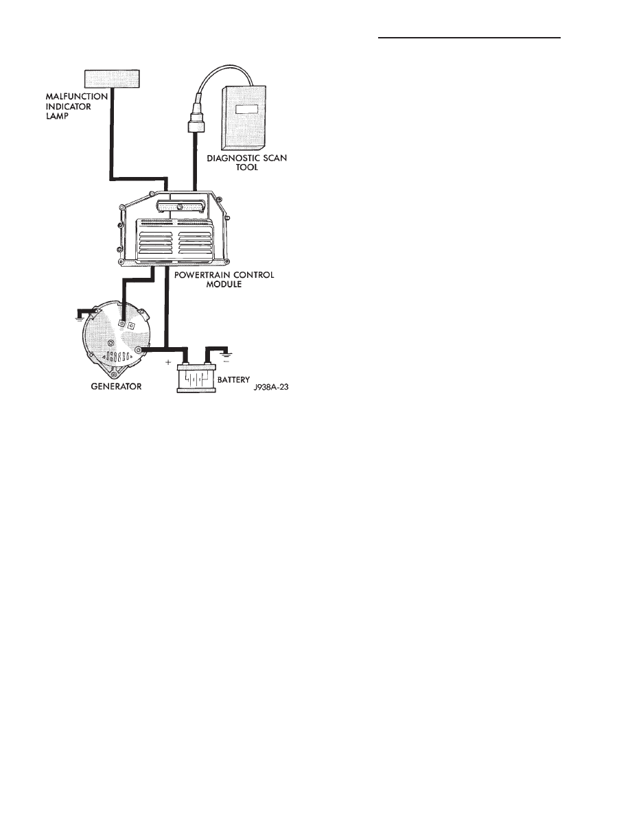
Fig. 2 Charging System Components
8A - 2
BATTERY/STARTING/CHARGING SYSTEMS DIAGNOSTICS
Z
When electrolyte level is below top of the plates
(yellow or bright indicator), distilled water should be
added. The battery must be completely charged
(green indicator) and the top, posts, and terminals
should be properly cleaned before diagnostic proce-
dures
are
performed.
Refer
to
Group
8B
-
Battery/Starter Service, for additional information.
All batteries are protected from high underhood
temperatures by a thermal shield. Always install
shield after removing the battery.
BATTERY TESTING GENERAL INFORMATION
Before testing a battery, clean the top of the
battery case, posts and cable terminals.
Specific gravity is a ratio of the density of the
electrolyte and the density of pure water. The electro-
lyte is composed of sulfuric acid and water. Acid
makes up approximately 35% by weight or 24% by
volume.
The condition of a battery may be determined from
the results of 3 tests:
• state of charge, using test indicator
• hydrometer test
• ability to supply current (battery load test).
Use test indicator first. If battery condition is not
certain then perform the Hydrometer test. If the spe-
cific gravity is less than 1.225, (with battery at room
temperature) the battery must be charged before pro-
ceeding with further testing. A battery that will not
accept a charge is defective and further testing is not
necessary.
Completely discharged batteries may take sev-
eral hours to accept a charge. See Charging A
Completely Discharged Battery.
A battery that has been fully charged but does not
pass the battery load test is defective.
A battery is fully charged when:
• all cells are gassing freely during charging
• 3 corrected specific gravity tests, taken at 1-hour
intervals, indicate no increase in specific gravity.
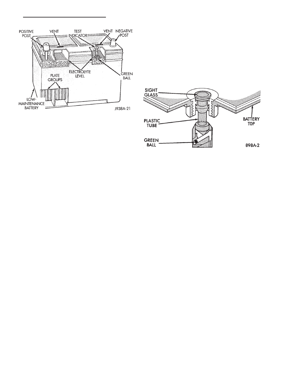
TEST INDICATOR
A test indicator (hydrometer) built into the top of
battery case, provides visual information for battery
testing (Fig. 4). It is important when using test indi-
cator that the battery be level and have a clean top to
see correct indications. A light may be required to
view indicator.
WARNING: DO NOT USE OPEN FLAME. EXPLOSIVE
GASES FORM ABOVE BATTERY.
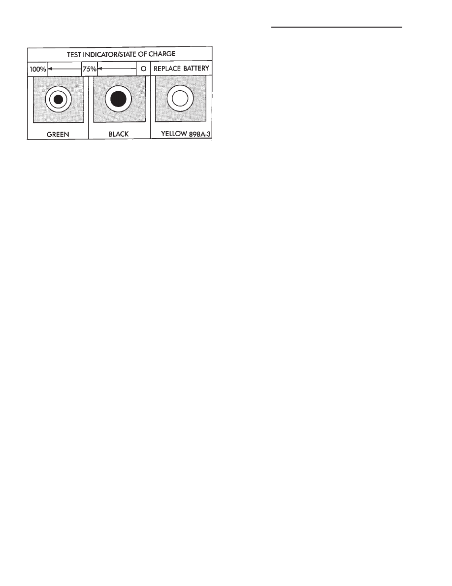
STATE OF CHARGE TEST USING TEST INDICATOR
The built-in test indicator (hydrometer) measures
the specific gravity of the electrolyte. Specific gravity
(SG) will indicate state-of-charge (voltage); although,
the test indicator will not indicate cranking capacity
of the battery. Refer to Battery Load Test for more
information. Look into the sight glass and note the
color of the indicator (Fig. 5), refer to the following
description as color indicates:
GREEN—75 to 100% state-of-charge
The battery is adequately charged for further test-
ing or return to use. If the vehicle will not crank for a
maximum 15 seconds, refer to Battery Load Test for
more information.
BLACK OR DARK—0 to 75% state-of-charge
The battery is inadequately charged and must be
charged until green indicator is visible (12.4 volts or
more) before the battery is tested or returned to use.
Refer to Causes of Battery Discharging for more in-
formation.
YELLOW OR BRIGHT COLOR
WARNING: DO NOT ATTEMPT TO CHARGE, TEST,
OR ASSIST BOOST BATTERY WHEN YELLOW OR
BRIGHT COLOR IS VISIBLE. PERSONAL INJURY
MAY OCCUR.
A yellow or bright color indicates electrolyte level in
the battery is below test indicator (Fig. 5). Water can
be added to a low maintenance battery. A low electro-
lyte level may be caused by an over charging condi-
tion. Refer to Generator Test Procedures On Vehicle
in this group.
Fig. 3 Battery Construction and Test Indicator
Fig. 4 Built in Test Indicator
Z
BATTERY/STARTING/CHARGING SYSTEMS DIAGNOSTICS
8A - 3
HYDROMETER TEST
Before performing a hydrometer test, remove
the battery caps and check the electrolyte level.
Add distilled water as required.
Before testing, visually inspect the battery for dam-
age (cracked case or cover, loose post, etc.) that would
cause the battery to be defective. To use the hydrom-
eter correctly, hold it with the top surface of the
electrolyte at eye level. Refer to manufacturers in-
structions for correct use of hydrometer.
Remove only enough electrolyte from the battery to
keep the float off the bottom of the hydrometer barrel
with pressure on the bulb released. Exercise care
when inserting the tip of the hydrometer into a cell to
avoid damage to the separators. Damaged separators
can cause premature battery failure.
Hydrometer floats are generally calibrated to indi-
cate the specific gravity correctly only at one fixed
temperature, 80°F (26.6°C). When testing the specific
gravity at any other temperature, a correction factor
is required.
The correction factor is approximately a specific
gravity value of 0.004, referred to as 4 points of
specific gravity. For each 10°F above 80°F (5.5°C
above 26.6°C), add 4 points. For each 10°F below 80°F
(5.5°C below 26.6°C), subtract 4 points. Always cor-
rect the specific gravity for temperature variation.
Test the specific gravity of the electrolyte in each
battery cell.
Example: A battery is tested at 10°F (-12.2°C) and
has a specific gravity of 1.240. Determine the actual
specific gravity as follows:
• Determine the number of degrees above or below
80°F.
80°F - 10°F = 70°F
• Divide the result above by 10.
70°F/10 = 7
• Multiply the result from the previous step by the
temperature correction factor (0.004).
7 x 0.004 = 0.028
• The temperature at testing was below 80°F, there-
fore the temperature correction is subtracted.
1.240 - 0.028 = 1.212
The corrected specific gravity is 1.212.
The fully charged battery should have a tempera-
ture corrected specific gravity of 1.260 to 1.290
If the specific gravity of all cells is above 1.235, but
variation between cells is more than 50 points (0.050),
it is a sign that the battery should be replaced.
If the specific gravity of one or more cells is less
than 1.235, recharge the battery at a rate of approxi-
mately 5 amperes. Continue charging until 3 consecu-
tive specific gravity tests, taken at one-hour intervals,
are constant.
If the cell specific gravity variation is more than 50
points (0.050) at the end of the charge period, replace
the battery.
When the specific gravity of all cells is above 1.235
and variation between cells is less than 50 points
(0.050), the battery may be tested under heavy load.
CAUSES OF BATTERY DISCHARGING
It is normal to have a 5 to 20 milliamperes Ignition
Off Draw (IOD) from the battery with all lamps OFF.
Electronic features or accessories that have a memory
circuit cause IOD. When a vehicle is not used for 20
days or more, remove IOD fuse in the Power Distribu-
tion Center to reduce battery discharging.
ABNORMAL BATTERY DISCHARGING
(1) Corroded battery posts and terminals.
(2) Loose or worn generator drive belt.
(3) Electrical loads that exceed the output of the
charging system due to equipment or accessories in-
stalled after delivery.
(4) Slow driving speeds (heavy traffic conditions) or
prolonged idling with high-amperage draw systems in
use.
(5) Defective circuit or component causing excess
IOD. Refer to Ignition Off Draw in this Group.
(6) Defective charging system.
(7) Defective battery.
BATTERY OPEN CIRCUIT VOLTAGE TEST
A battery voltage (no load) test will show state of
charge of a battery that will pass the Battery Load
Test described in this section. Before proceeding
with this test or Battery Load Test, completely
charge battery as described in Battery Charg-
ing in this section.
If a battery has a no load voltage reading of 12.4
volts or greater and will not endure a load test, it is
defective and should be replaced. Refer to Group 8B -
Battery/Starter Service for instructions. To test bat-
tery no load voltage, perform the following operation:
(1) Before measuring open circuit voltage, the sur-
face charge must be removed from plates. Turn head
lights on for 15 seconds then allow up to 5 minutes
for voltage to stablize.
(2) Remove both battery cables, negative first.
Fig. 5 Test Indicator Sight Glass
8A - 4
BATTERY/STARTING/CHARGING SYSTEMS DIAGNOSTICS
Z
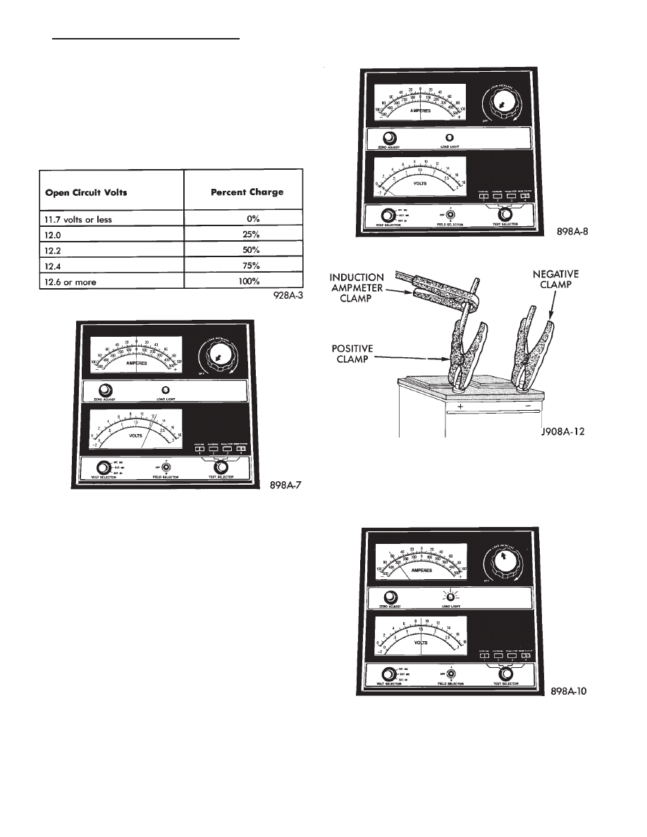
(3) Using a voltmeter connected to the battery
posts, see instructions provided with voltmeter, mea-
sure open circuit voltage (Fig. 6).
This voltage reading will indicate state of charge,
but will not reveal cranking capacity. Refer to Battery
Open Circuit Voltage chart.
BATTERY LOAD TEST
WARNING: IF BATTERY SHOWS SIGNS OF FREEZ-
ING, LEAKING, LOOSE POSTS, OR LOW ELECTRO-
LYTE LEVEL, DO NOT TEST. ACID BURNS OR EX-
PLOSIVE CONDITION MAY RESULT.
A battery load test will verify the cranking ability
based on the cold crank rating of the battery.
Before performing battery load test, the bat-
tery must be FULLY CHARGED.
(1) Remove both battery cables, negative first. Bat-
tery top and posts should be clean. If indicator is not
green, charge the battery. See Battery Charging Pro-
cedures in this section.
(2) Connect a suitable Volt-Ammeter-Load tester
(Fig. 7) to the battery posts (Fig. 8). Refer to operat-
ing instructions provided with the tester being used.
Check the open circuit voltage (no load) of the battery.
Voltage should be equal to or greater than 12.4 volts
(Fig. 7) with a green test indicator.
(3) Rotate the load control knob (carbon pile rheo-
stat) to apply a 300 amp load for 15 seconds then
return the control knob to off (Fig. 9). This will re-
move the surface charge from the battery.
(4) Allow the battery to stabilize to open circuit
voltage (may take up to 5 minutes).
(5) Rotate the load control knob to maintain a load
(50% of cold crank rating—see Specifications) for a
BATTERY OPEN CIRCUIT VOLTAGE
Fig. 6 Testing Open Circuit Voltage
Fig. 7 Volt-Amps-Load Tester (Typical)
Fig. 8 Volt-Ammeter-Load Tester Connections
Fig. 9 Remove Surface Charge from Battery
Z
BATTERY/STARTING/CHARGING SYSTEMS DIAGNOSTICS
8A - 5
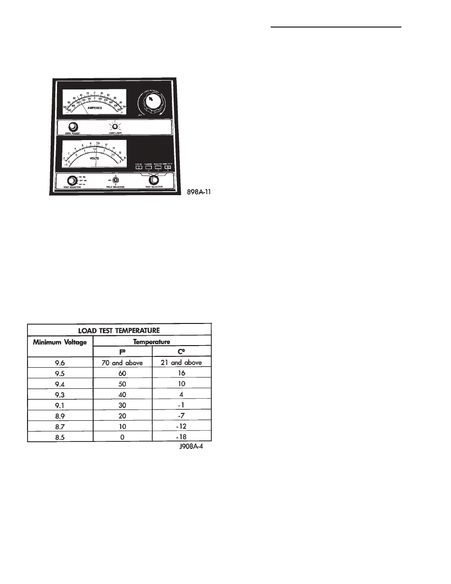
minimum of 15 seconds (Fig. 10). After 15 seconds,
record the (loaded) voltage reading and return the
load control to off.
(6) Voltage drop will vary according to battery tem-
perature at the time of the load test. Battery tem-
perature can be estimated by the ambient tempera-
ture over the past several hours. If the battery has
been charged, boosted, or loaded a few minutes prior
to test, the battery would be somewhat warmer. Refer
to Load Test Temperature chart for proper loaded
voltage reading.
(7) If the voltmeter reading fell below 9.6 volts,
with the battery temperature at a minimum of 70°F
(21°C), replace the battery.
BATTERY CHARGING
A battery is completely charged when it has:
• an open circuit voltage of 12.4 volts or more.
• has enough cranking capacity (minimum 9.6 volts
when loaded for 15 seconds to 50% of cold cranking
amperage rating at 21°C/70°F).
A green test indicator on the top of the battery,
indicates the battery is charged enough for further
testing. A black indicator means the battery state of
charge is below 75%. A yellow or bright indicator
means the battery has low electrolyte level. Add dis-
tilled water as required.
WARNING: DO NOT CHARGE A BATTERY THAT HAS
LOW ELECTROLYTE LEVEL. BATTERY MAY ARC
INTERNALLY AND EXPLODE.
WARNING: EXPLOSIVE GASES FORM OVER BAT-
TERY, DO NOT SMOKE, USE FLAME, OR CREATE
SPARKS NEAR BATTERY.
WARNING: DO NOT ASSIST BOOST OR CHARGE A
FROZEN BATTERY, CASING MAY FRACTURE.
WARNING: POISON, CAUSES SEVERE BURNS. BAT-
TERY CONTAINS SULFURIC ACID, AVOID CONTACT
WITH SKIN, EYES, OR CLOTHING. IN EVENT OF
CONTACT, FLUSH WITH WATER AND CALL PHYSI-
CIAN IMMEDIATELY. KEEP OUT OF REACH OF
CHILDREN.
CAUTION: Disconnect the vehicle’s battery negative
cable before charging battery to avoid damage to
electrical systems. Do not exceed 16.0 volts while
charging battery.
Battery electrolyte will bubble inside case while
being charged properly. If the electrolyte boils or is
discharged from the vent holes while charging, imme-
diately reduce charging rate or turn off charger. De-
termine battery condition.
Battery should not be hot to touch.
If the battery feels hot to the touch, turn off
charger and let cool before restarting.
Some battery chargers are equipped with polarity
(+ to +/- to -) sensing devices to protect the charger or
battery from being damaged if improperly connected.
If the battery state of charge is too low for the polar-
ity sensor to detect, the sensor must be bypassed for
charger to operate. Refer to operating instructions
provided with battery charger being used.
CAUTION: Charge battery until test indicator ap-
pears green. Do not overcharge.
It may be necessary to jostle the battery or vehicle
to bring green ball into view in the test indicator
when state-of-charge has reached 75%.
After the battery has been charged, green indicator,
perform a load test to determine cranking capacity. If
the battery will endure a load test, return the battery
to use. If battery will not endure a load test, it must
be
replaced.
Clean
and
inspect
battery
hold
Fig. 10 Load 50% Cold Crank Rating Note Voltage
8A - 6
BATTERY/STARTING/CHARGING SYSTEMS DIAGNOSTICS
Z
downs, tray, terminals, posts, and top before complet-
ing service, see Group 8B - Battery/Starter/Generator
Service.
CHARGING TIME REQUIRED
The time required to charge a battery will vary
depending upon the following factors:
(1) Size of Battery— A completely discharged
large, heavy-duty battery requires more than twice
the recharging time as a completely discharged small
capacity battery.
WARNING:
NEVER
EXCEED
20
AMPS
WHEN
CHARGING A COLD (-1°C/30°F) BATTERY, PER-
SONAL INJURY MAY RESULT.
(2) Temperature— A longer time will be needed to
charge a battery at -18°C (0°F) than at 27°C (80°F).
When a fast charger is connected to a cold battery,
current accepted by battery will be very low at first.
Then, in time, the battery will accept a higher rate as
battery warms.
(3) Charger Capacity— A charger, that supplies
only 5 amperes, will require a much longer charging
time than a charger that supplies 20 amperes or
more.
(4) State Of Charge— A completely discharged
battery requires more charging time than a partially
charged battery. Electrolyte is nearly pure water in a
completely discharged battery. At first the charging
current amperage will be low. As the battery charges
the specific gravity of the electrolyte will rise slowly.
CHARGING COMPLETELY DISCHARGED BAT-
TERY
The following procedure should be used to recharge
a completely discharged battery. Unless procedure is
properly followed, a good battery may be needlessly
replaced.
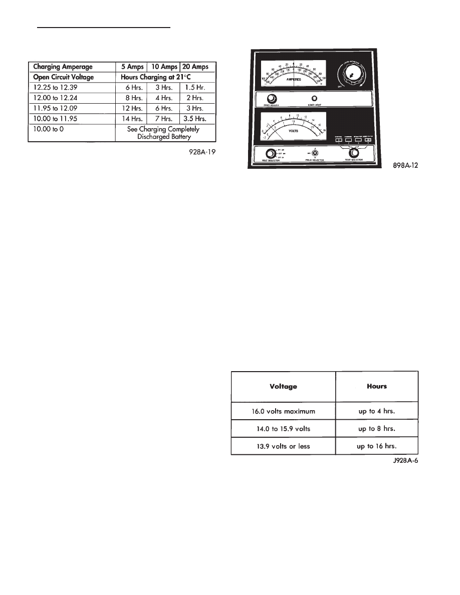
(1) Measure voltage at battery posts with a voltme-
ter, accurate to 1/10 volt (Fig. 11). If below 10 volts,
then charge current will be low and it could take
some time before it accepts a current greater than a
few milliamperes. Such low current may not be de-
tectable on ammeters built into many chargers.
(2) Connect charger leads. Some chargers feature
polarity protection circuitry that prevents operation
unless charger is connected to battery posts correctly.
A completely discharged battery may not have enough
voltage to activate this circuitry, even though leads
are connected properly. This makes it appear that
battery will not accept charging current. Refer to
instructions provided with battery charger being
used.
(3) Battery chargers vary in the amount of voltage
and current they provide. For time required for bat-
tery to accept measurable charger current at various
voltages, refer to Charge Rate chart. If charge current
is still not measurable at end of charging times, the
battery should be replaced. If charge current is mea-
surable during charging time, the battery may be
good and charging should be completed in the normal
manner.
BATTERY CHARGING TIME TABLE
Fig. 11 Voltmeter Accurate to 1/10 Volt Connected
CHARGE RATE
Z
BATTERY/STARTING/CHARGING SYSTEMS DIAGNOSTICS
8A - 7
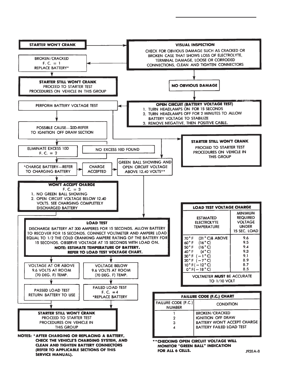
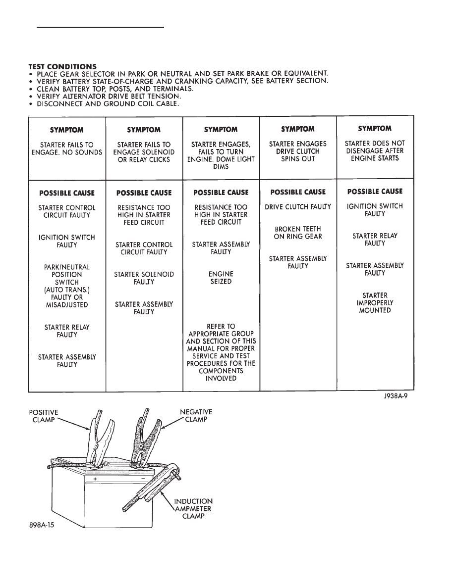
BATTERY DIAGNOSTICS CHART
8A - 8
BATTERY/STARTING/CHARGING SYSTEMS DIAGNOSTICS
Z

IGNITION OFF DRAW (IOD)
Ignition off draw refers to power being drained from
the battery with the ignition turned off. A normal
vehicle electrical system will draw from 5 to 20 milli-
amps. This is with the ignition in the OFF position,
and all non-ignition controlled circuits in proper
working order. A vehicle that has not been operated
for approximately 20 days, may discharge the battery
to an inadequate level. Battery drain should not ex-
ceed approximately 20 MA (20 milliamps = 0.020
amps).
The 20 MA are needed to supply PCM memory,
digital clock memory, ETR (electronically tuned radio)
and Security Alarm memory.
Excessive battery drain is caused by items left
turned on, internally shorted generator, or intermit-
tent short in wiring.
If IOD is over 20 milliamperes, the defect must be
found and corrected before replacing a battery. In
most cases the battery can be charged and returned
to service. See BATTERY CHARGING in this section.
TEST PROCEDURE
Testing for higher amperage IOD must be per-
formed first to prevent damage to most milli-
amp meters.
(1) If the vehicle is equipped with a Security Alarm
disconnect the Security Alarm relay that is located in
the relay center under the glove box.
(2) Verify that all electrical accessories are OFF.
Turn off all lights, remove ignition key, and close all
doors. If the vehicle is equipped with electronic acces-
sories (illuminated entry, high line radio), allow the
systems to automatically shut off (time out), up to 3
minutes.
(3) After determining that the underhood lamp is
operating properly then disconnect bulb.
(4) Disconnect negative cable from battery.
(5) Connect a typical 12 volt test light (low wattage
bulb) between the negative cable clamp and the bat-
tery negative terminal. If equipped with security
alarm, cycle the key in the door to turn off the flash-
ing lights. Make sure that the doors remain closed so
that illuminated entry is not activated.
The test light may light brightly for up to 3 minutes
or may not light at all (depending on the electrical
equipment). The term brightly being used throughout
the following tests, implies the brightness of the test
light will be the same as if it were connected across
the battery.
The test light must be securely clamped to the
negative cable and battery terminal. If the test light
becomes disconnected during any of the IOD test, the
electronic timer function will be activated and all
tests must be repeated.
If the ammeter circuit is broken the Security
alarm module will turn on parking lamps.
(6) After 3 minutes, the test light should turn OFF
or be DIMLY lit (depending on the electrical equip-
ment). If the test light remains brightly lit do not
disconnect it. Remove each fuse or circuit breaker
(refer to Group 8 - Wiring Diagrams) until test light is
either OFF or DIMLY lit. This will eliminate the
higher amperage draw.
If test light is still bright after disconnecting each
fuse and circuit breaker, disconnect the wiring har-
ness from the generator. Refer to Generator Testing
in this group. Do not disconnect the test light.
After higher amperage IOD has been corrected, low
amperage IOD may be checked.
It is now safe to install milliamp meter to check for
low amperage IOD.
(7) With test light still connected securely clamp an
ammeter between battery negative terminal and
negative battery cable.
If the test light or the milliamp meter circuit
is broken the Security alarm module will turn
on parking lamps. Do not open any doors or
turn on any electrical accessories with the test
light disconnected or the meter may be dam-
aged.
(8) Disconnect test light. The current draw should
not exceed 0.020 amp. If it exceeds 0.020 milliamps
isolate each circuit by removing circuit breakers and
fuses. The meter reading drops once the high current
problem is found. Repair this section of the circuit,
whether it is a wiring short or component failure.
Z
BATTERY/STARTING/CHARGING SYSTEMS DIAGNOSTICS
8A - 9
ENGINE STARTER MOTOR TEST PROCEDURES
INDEX
page
page
Cold Cranking Test . . . . . . . . . . . . . . . . . . . . . . . . 10
General Information
. . . . . . . . . . . . . . . . . . . . . . . 10
Ignition Switch Test
. . . . . . . . . . . . . . . . . . . . . . . 14
Park/Neutral Position Switch
. . . . . . . . . . . . . . . . . 14
Starter Control Circuit Tests
. . . . . . . . . . . . . . . . . 13
Starter Feed Circuit Tests - (Voltage Drop
Method)
. . . . . . . . . . . . . . . . . . . . . . . . . . . . . . 10
Starter System Diagnostic Inspections
. . . . . . . . . 10
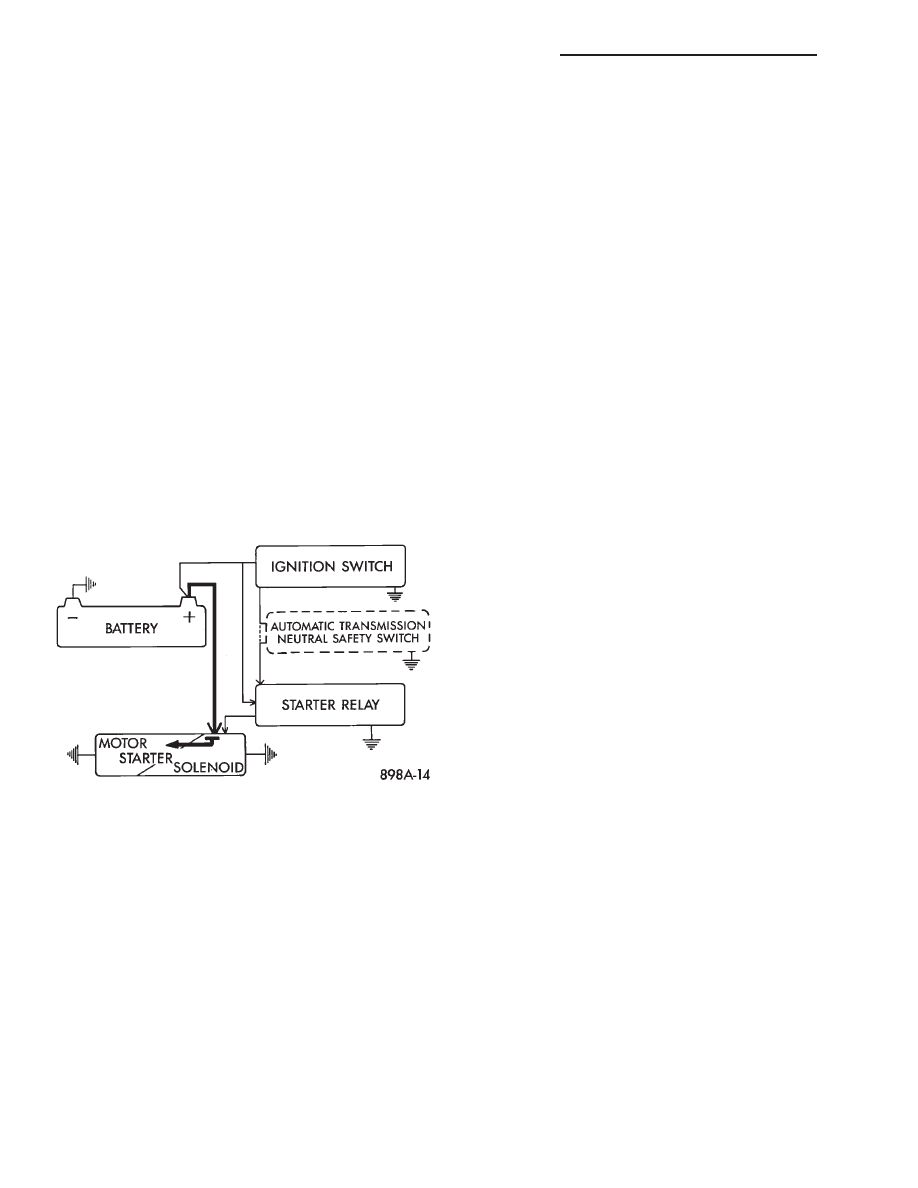
GENERAL INFORMATION
The starting system consists of an:
• ignition switch
• starter relay
• park/neutral position switch (automatic transmis-
sion)
• wiring harness
• battery
• starter motor with an integral solenoid.
These components form 2 separate circuits. A high
amperage circuit that feeds the starter motor up to
300+ amps, and a control circuit that operates on less
than 20 amps (Fig. 1).
STARTER SYSTEM DIAGNOSTIC INSPECTIONS
Before removing any unit from the starter motor
system for repair, perform the following inspections:
BATTERY INSPECTION
To determine condition of the battery, perform the
testing procedure outlined in the Battery Section.
WIRING INSPECTION
Inspect wiring for damage. Inspect all connections
at the starter motor solenoid, park/neutral position
switch (if equipped), back-up lamp switch connector,
ignition/start
switch,
and
battery
(including
all
ground connections). Clean and tighten all connec-
tions as required.
SOLENOID, RELAY AND IGNITION/START
SWITCH INSPECTION
Inspect the solenoid, relay and switch to determine
their condition. Also, if equipped with automatic
transmission, inspect condition of the park/neutral
position switch. Testing information can be found in
the following pages.
If the following components are working properly
remove the starter motor and follow procedures in the
Testing Section.
• battery
• wiring
• switch
• solenoid
• relay
• park/neutral position switch
COLD CRANKING TEST
(1) Battery must first pass load and voltage drop
tests and be fully charged before proceeding. Refer to
Battery Test Procedures.
(2) Connect a suitable volt-ampere tester to the
battery terminals (Fig. 2). Refer to the operating in-
structions provided with the tester being used.
(3) Fully engage parking brake, place manual
transmission in NEUTRAL, automatic transmission
in PARK.
(4) Verify that all lights and accessories are OFF.
(5) Remove coil secondary cable from distributor
and connect to ground.
(6) Rotate and hold the ignition switch (key) in the
START position. Note cranking voltage and amperage.
(a) If voltage reads above 9.6 volts and amperage
draw reads above specifications, go to Starter Feed
Circuit Tests.
(b) If voltage reads 12.5 volts or greater and am-
perate reads 0 to 10 amps, go to Starter Control
Circuit Tests.
A cold engine will increase starter motor current.
STARTER FEED CIRCUIT TESTS - (VOLTAGE DROP
METHOD)
The voltage drop tests will determine if there is
excessive resistance in the high current circuit. When
performing these tests, it is important that the volt-
Fig. 1 Starting System Components
8A - 10
BATTERY/STARTING/CHARGING SYSTEMS DIAGNOSTICS
Z
meter be connected to the terminals that the cables
are connected to instead of to the cables themselves.
For example, when testing between the battery and
solenoid, touch the voltmeter test probes to the bat-
tery post and the solenoid threaded stud. The follow-
ing operation will require a voltmeter, accurate to
1/10 of a volt.
Before performing the tests, assure the following
procedures are accomplished:
• remove coil secondary cable from distributor and
connect to ground
• transmission in NEUTRAL (manual transmission)
or PARK (automatic transmission)
• parking brake applied
• battery is fully charged (refer to Battery Test Pro-
cedures).
STARTING SYSTEM DIAGNOSIS
Fig. 2 Volt-Amps Tester Connections (Typical)
Z
BATTERY/STARTING/CHARGING SYSTEMS DIAGNOSTICS
8A - 11
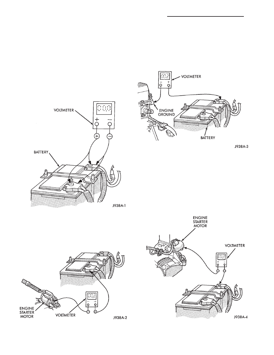
(1) Connect positive lead of the voltmeter to the
battery negative post. Connect negative lead to the
battery negative cable clamp (Fig. 3). Rotate and hold
the ignition switch (key) in the START position. Ob-
serve the voltmeter. If voltage is detected, correct poor
contact between the cable clamp and post.
(2) Connect positive lead of voltmeter to the battery
positive post. Connect negative lead to the battery
cable positive clamp (Fig. 3). Rotate and hold the
ignition switch (key) in the START position. Observe
the voltmeter. If voltage is detected, correct poor con-
tact between the cable clamp and post.
(3) Connect a voltmeter to measure between the
battery positive post and the center of the B+ starter
solenoid stud (Fig. 4).
(4) Rotate and hold the ignition with (key) in the
START position. If voltage reads above 0.2 volt, cor-
rect poor contact at battery cable to solenoid connec-
tion. If reading is still above 0.2 volt, replace positive
battery cable.
(5) Connect the voltmeter to measure between the
battery negative post and the engine block (Fig. 5).
(6) Rotate and hold the ignition with (key) in the
START position. If voltage reads above 0.2 volt, cor-
rect poor contact at ground cable attaching point.
Voltage reading still above 0.2 volt, replace ground
cable.
(7) Connect positive voltmeter lead to the starter
motor housing and the negative lead to the battery
negative terminal (Fig. 6).
Fig. 3 Test Battery Connection Resistance
Fig. 4 Test Positive Battery Cable Resistance
(Typical)
Fig. 5 Test Ground Circuit Resistance
Fig. 6 Test Starter Motor Ground (Typical)
8A - 12
BATTERY/STARTING/CHARGING SYSTEMS DIAGNOSTICS
Z
(8) Rotate and hold the ignition switch (key) in the
START position. If voltage reads above 0.2 volt, cor-
rect poor starter to engine ground.
If resistance tests detect no feed circuit failures,
remove the starter motor and go to Bench Testing
Starter Solenoid.
STARTER CONTROL CIRCUIT TESTS
The starter control circuit consists of a:
• starter solenoid
• starter relay
• ignition switch
• park/neutral position switch (automatic transmis-
sion)
• all their wiring and connections.
Testing procedures for these components are as fol-
lows and should be followed in order as described.
CAUTION: Before performing any test disconnect
distributor connector to prevent engine from start-
ing.
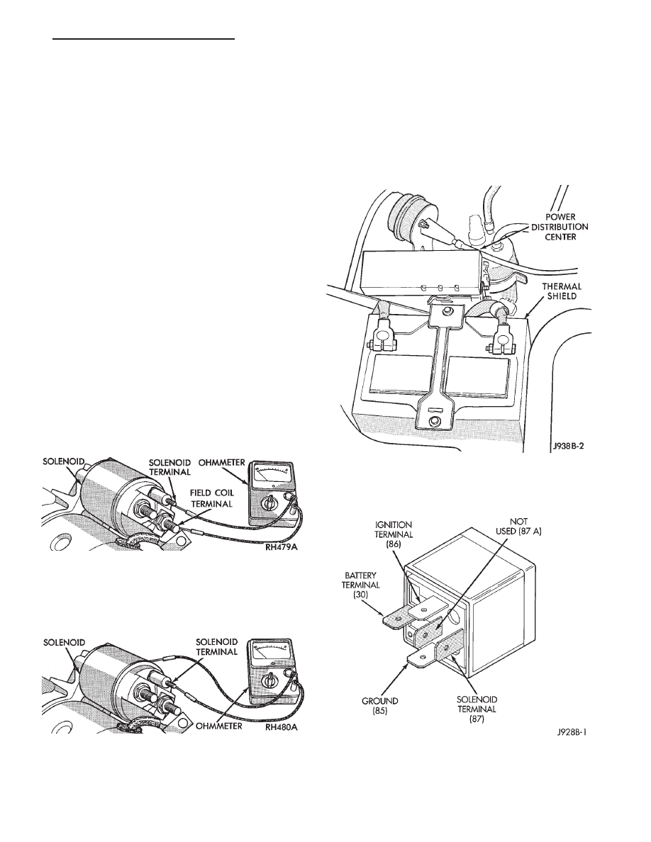
SOLENOID TESTING
Refer to Group 8B - Battery Starter Service for
starter removal procedures.
(1) Disconnect field coil wire from field coil termi-
nal.
(2) Check for continuity between solenoid terminal
and field coil terminal with a continuity tester. There
should be continuity (Fig. 7).
(3) Check for continuity between solenoid terminal
and solenoid housing. There should be continuity
(Fig. 8).
(4) If there is continuity, solenoid is good. If there is
no continuity in either test, solenoid has an open
circuit and is defective. Replace starter motor.
(5) Install starter as described in Group 8B -
Battery/Starter/Generator Service.
(6) Connect field coil wire to field coil terminal.
STARTER RELAY OPERATION/TESTING
The starter relay is in the Power Distribution Cen-
ter (Fig. 9). Refer to the underside of the Power
Distribution Cover for relay location.
OPERATION
• The battery terminal (30) is usually connected to
battery voltage and can be switched or B+ at all
times.
Fig. 7 Continuity Test Between Solenoid Terminal
and Field Coil Terminal
Fig. 8 Continuity Test Between Solenoid Terminal
and Solenoid Case
Fig. 9 Power Distribution Center
ENGINE STARTER RELAY CONNECTIONS
Z
BATTERY/STARTING/CHARGING SYSTEMS DIAGNOSTICS
8A - 13

• Terminal No. 87A is connected to terminal 30 in
the de-energized position.
• The solenoid terminal (87) is connected to the bat-
tery terminal (30) in the energized position which
supplies battery voltage to the operated device.
• The ignition terminal (86) is connected to the elec-
tromagnet and usually connected to a switched power
source.
• The ground terminal (85) is connected to the elec-
tromagnet and is usually grounded by a switch or the
PCM.
TESTING
Remove relay from the Power Distribution Center
to perform the following tests.
• A relay in the de-energized position should have
continuity between terminal 87A and terminal 30.
• Resistance value between terminals 85 and 86
(electromagnet) is 75
65 ohms.
• Connect a battery to terminals 85 and 86. There
should be continuity between terminal 30 and 87.
IGNITION SWITCH TEST
After testing starter solenoid and relay and they
check out okay, trouble is probably with ignition
switch or its wiring.
Check all wiring for opens and shorts and connec-
tions for being loose or corroded.
PARK/NEUTRAL POSITION SWITCH
Refer to Group 21 - Transmissions for diagnostic
information.
8A - 14
BATTERY/STARTING/CHARGING SYSTEMS DIAGNOSTICS
Z
GENERATOR TEST PROCEDURES ON VEHICLE
INDEX
page
page
Current Output Test
. . . . . . . . . . . . . . . . . . . . . . . 16
Diagnostic Procedures
. . . . . . . . . . . . . . . . . . . . . 15
General Information
. . . . . . . . . . . . . . . . . . . . . . . 15
How to Use Malfunction Indicator Lamp for
Diagnostic Trouble Codes
. . . . . . . . . . . . . . . . . 18
Operational Check with Battery Indicator (Base
Cluster Only)
. . . . . . . . . . . . . . . . . . . . . . . . . . 15
Operational Check with Voltmeter
. . . . . . . . . . . . . 15
Output Wire Resistance Test
. . . . . . . . . . . . . . . . 16
Using On-Board Diagnostic System
. . . . . . . . . . . 17
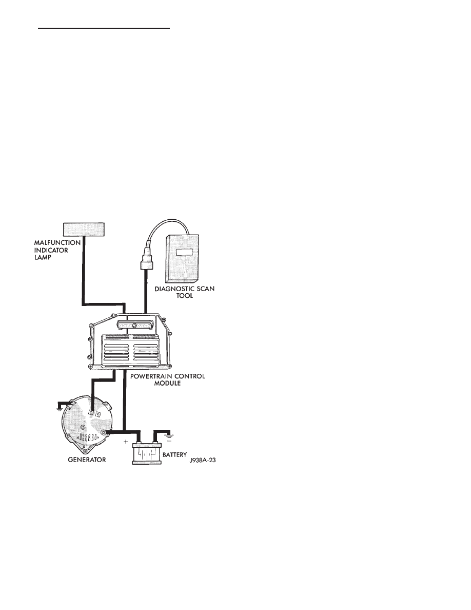
GENERAL INFORMATION
The generator is belt-driven by the engine. All en-
gines use serpentine drive.
The amount of DC current produced by the genera-
tor is controlled by the Powertrain Control Module
(PCM) (Fig. 1).
All vehicles are equipped with On Board Diagnos-
tics (OBD). All OBD sensing systems are monitored
by the PCM. The PCM will store in electronic memory
any detectable failure within the monitored circuits.
Refer to USING ON-BOARD DIAGNOSTIC SYSTEM
in this group for more information.
OPERATIONAL CHECK WITH BATTERY INDICATOR
(BASE CLUSTER ONLY)
When operating normally, the indicator bulb will
come on when the ignition switch is turned to the
RUN or START position. After the engine starts, the
indicator bulb goes off. With the engine running, the
charge indicator should come on only when there is a
problem in the charging system (base cluster only).
OPERATIONAL CHECK WITH VOLTMETER
When the ignition switch is turned to the RUN
position, battery potential will register on the voltme-
ter. During engine cranking a lower voltage will ap-
pear on the meter. With the engine running, a voltage
reading higher than the first reading (ignition in
RUN) should register.
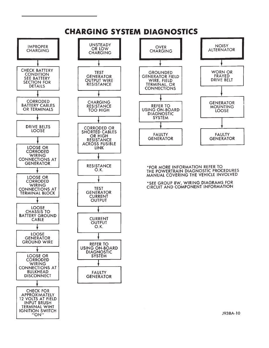
DIAGNOSTIC PROCEDURES
If the indicator does not operate properly, or if an
undercharged or overcharged battery condition oc-
curs, the following procedures may be used to diag-
nose the charging system.
Remember that an undercharged battery is often
caused by:
• accessories being left on overnight
• or by a defective switch
which allows a bulb, such as a trunk or glove box
light, to stay on (refer to Ignition Off Draw).
VISUAL INSPECTION
• Inspect condition of battery cable terminals, bat-
tery posts, connections at engine block, starter motor
solenoid and relay. They should be clean and tight.
Repair as required.
• Inspect all fuses in the fuse block for tightness in
receptacles. They should be properly installed and
tight. Repair or replace as required.
• Inspect the electrolyte level in the battery and add
water if necessary.
• Inspect generator mounting bolts for tightness. Re-
place or torque bolt as required (refer to Torque Speci-
fications).
• Inspect generator drive belt condition and tension.
Tension or replace belt as required. Refer to Belt
Tension Specifications.
Fig. 1 Charging System Components (Typical)
Z
BATTERY/STARTING/CHARGING SYSTEMS DIAGNOSTICS
8A - 15

• Inspect connection at generator B+ output. It
should be clean and tight. Repair as required.
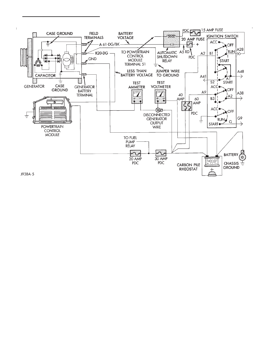
OUTPUT WIRE RESISTANCE TEST
Generator output wire resistance test will show
amount of Voltage Drop across generator output wire
between generator BAT terminal and battery positive
post.
PREPARATION
(1) Before starting test make sure vehicle has a
fully charged battery. Test and procedures on how to
check for a fully charged battery are shown in Battery
section of this Group.
(2) Turn OFF ignition switch.
(3) Disconnect negative cable from the battery.
(4) Disconnect generator output wire from genera-
tor output Battery terminal.
(5) Connect a 0-150 ampere scale D.C. ammeter in
series between generator BAT terminal and discon-
nected generator output wire (Fig. 2). Connect Posi-
tive lead to generator BAT terminal and Negative
lead to disconnected generator output wire.
(6) Connect Positive lead of a test voltmeter (Range
0-18 volts minimum) to disconnected generator out-
put wire. Connect negative lead of test voltmeter to
battery positive cable at positive post.
(7) Connect one end of a Jumper Wire to ground
and with other end probe green K20 lead wire at back
of generator (Fig. 2). (This will generate a DTC).
CAUTION: Do not connect dark green/black A61 lead
of wiring to ground. Refer to Group 8W - Wiring
Diagrams for more information.
(8) Connect an engine tachometer and connect
negative cable to battery.
(9) Connect a variable carbon pile rheostat between
battery terminals. Be sure carbon pile is in ‘‘Open’’ or
‘‘Off ’’ position before connecting leads. See Battery
Section, Load Testing for instructions.
TEST
(1) Start engine. Immediately after starting, reduce
engine speed to idle.
(2) Adjust engine speed and carbon pile to maintain
20 amperes flowing in circuit. Observe voltmeter
reading. Voltmeter reading should not exceed 0.5
volts.
RESULTS
If a higher voltage drop is indicated, inspect, clean
and tighten all connections between generator BAT
terminal and battery Positive post. A voltage drop test
may be performed at each connection to locate con-
nection with excessive resistance. If resistance tested
satisfactorily, reduce engine speed, turn off carbon
pile and turn off ignition switch.
(1) Disconnect negative cable from battery.
(2) Remove test ammeter, voltmeter, carbon pile,
and tachometer.
(3) Remove ‘‘Jumper Wire’’.
(4) Connect generator output wire to generator
BAT terminal post. Tighten to 5 to 6 N
Im (45 to 75
in. lbs.).
(5) Connect negative cable to battery.
(6) Use DRB II scan tool to erase DTC.
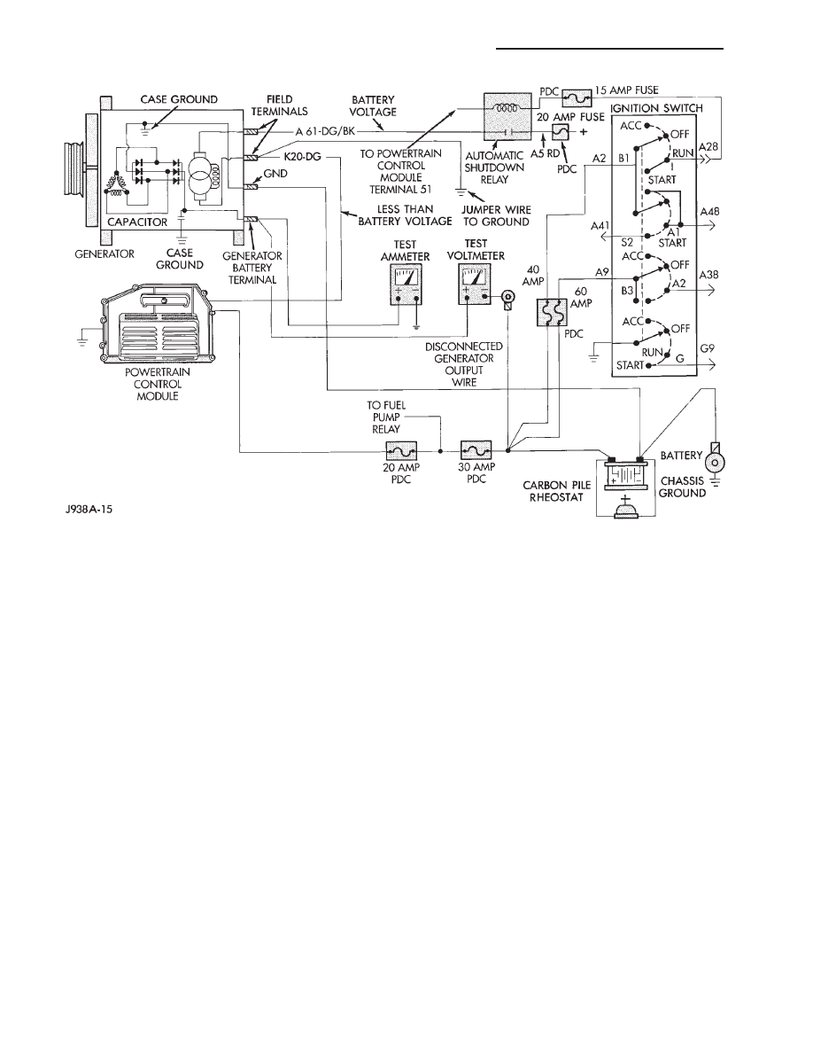
CURRENT OUTPUT TEST
Generator output test determines whether genera-
tor can deliver its rated current output.
PREPARATION
(1) Before starting any tests make sure vehicle has
a fully charged battery. Test and procedures on how to
check for a fully charged battery are shown in Battery
section of this Group.
(2) Disconnect negative cable from battery.
(3) Disconnect generator output wire at the genera-
tor battery terminal.
(4) Connect a 0-150 ampere scale D.C. ammeter in
series between generator BAT terminal and discon-
nected generator output wire (Fig. 3). Connect Posi-
tive lead to generator BAT terminal and negative lead
to disconnected generator output wire.
(5) Connect positive lead of a test voltmeter (range
0-18 volts minimum) to generator BAT terminal.
(6) Connect negative lead of test voltmeter to a
good ground.
(7) Connect an engine tachometer and connect bat-
tery negative cable.
(8) Connect a variable carbon pile rheostat between
battery terminals. Be sure carbon pile is in OPEN or
OFF position before connecting leads. See Battery
section, Load Testing for instructions.
(9) Connect one end of a Jumper Wire to ground
and with other end probe green K20 lead wire at back
of generator (Fig. 3). (This will generate a DTC).
CAUTION: Do not connect dark green/black A61 lead
of wiring to ground. Refer to Group 8W - Wiring
Diagrams for more information.
TEST
(1) Start engine. Immediately after starting reduce
engine speed to idle.
(2) Adjust carbon pile and engine speed in incre-
ments until a speed of 1250 rpm and voltmeter read-
ing of 15 volts is obtained.
CAUTION: Do not allow voltage meter to read above
16 volts.
8A - 16
BATTERY/STARTING/CHARGING SYSTEMS DIAGNOSTICS
Z
(3) The ammeter reading must be within limits
shown in generator specifications in back of this
group.
RESULTS
(1) If reading is less than specified and generator
output wire resistance is not excessive, generator
should be replaced; refer to Group 8C - Generator
Service for information.
(2) After current output test is completed reduce
engine speed, turn off carbon pile and turn off igni-
tion switch.
(3) Disconnect negative cable from battery.
(4) Remove test ammeter, voltmeter, tachometer
and carbon pile.
(5) Remove Jumper Wire (Fig. 3).
(6) Connect generator output wire to generator
BAT terminal post. Tighten nut to 8.5
61.5 NIm
(75
615 in. lbs.).
(7) Connect negative cable to battery.
(8) Use DRB II scan tool to erase DTC.
USING ON-BOARD DIAGNOSTIC SYSTEM
OPERATION OF ON-BOARD DIAGNOSTIC
(OBD) SYSTEM
The Powertrain Control Module monitors critical
input and output circuits of the charging system mak-
ing sure they are okay. Some are checked continu-
ously and some are checked only under certain condi-
tions.
If the OBD system senses that one critical circuit is
bad, it will consider this a real problem and put a
DTC into memory. Each input and output circuit
monitored by the OBD system has its own DTC. The
DTC will stay in memory as long as the circuit contin-
ues to be bad. If the problem does not happen again
after the DTC is put into memory, the Powertrain
Control Module will clear the memory after 50 to 100
engine starts.
DIAGNOSTIC TROUBLE CODES
Diagnostic trouble codes are two-digit numbers
flashed on Malfunction Indicator lamp that identify
which circuit is bad. In most cases they do not iden-
tify which component in a circuit is bad. A DTC
description can be read using the DRB II scan tool.
Refer to Group 14 - Fuel Systems for more informa-
tion. Therefore, a DTC is only a result, not necessar-
ily the reason for the problem. In some cases, because
of the design of the driveability test procedure, a DTC
can be the reason for the problem. It is important
that the test procedure be followed to understand
what the DTC of the on-board diagnostic system are
trying to tell.
Fig. 2 Generator Output Wire Resistance Test (Typical)
Z
BATTERY/STARTING/CHARGING SYSTEMS DIAGNOSTICS
8A - 17
HOW TO USE MALFUNCTION INDICATOR LAMP
FOR DIAGNOSTIC TROUBLE CODES
To start this function, cycle the ignition switch on-
off-on-off-on within 5 seconds. This will allow any
fault stored in the Powertrain Control Module to be
displayed. The Malfunction Indicator lamp will dis-
play a DTC by flashing on and off. There is a short
pause between flashes and a longer pause between
digits. All codes displayed are two digit numbers with
a four second pause between codes.
An example of a code is as follows:
(1) Lamp on for 2 seconds, then turns off.
(2) Lamp flashes 4 times pauses and then flashes 1
time.
(3) Lamp pauses for 4 seconds, flashes 4 times,
pauses and then flashes 7 times.
The two codes are 41 and 47. Any number of codes
can be displayed as long as they are in memory. The
lamp will flash until all are displayed (55 = End of
test).
CHARGING SYSTEM DIAGNOSTIC TROUBLE
CODES
See Generator Diagnostic Trouble Code Chart for
DTC which apply to the charging system. Refer to the
Powertrain Diagnostic Procedures Manual to diag-
nose an On-Board Diagnostic System, Diagnostic
Trouble Code.
Fig. 3 Generator Current Output Test (Typical)
8A - 18
BATTERY/STARTING/CHARGING SYSTEMS DIAGNOSTICS
Z
Z
BATTERY/STARTING/CHARGING SYSTEMS DIAGNOSTICS
8A - 19
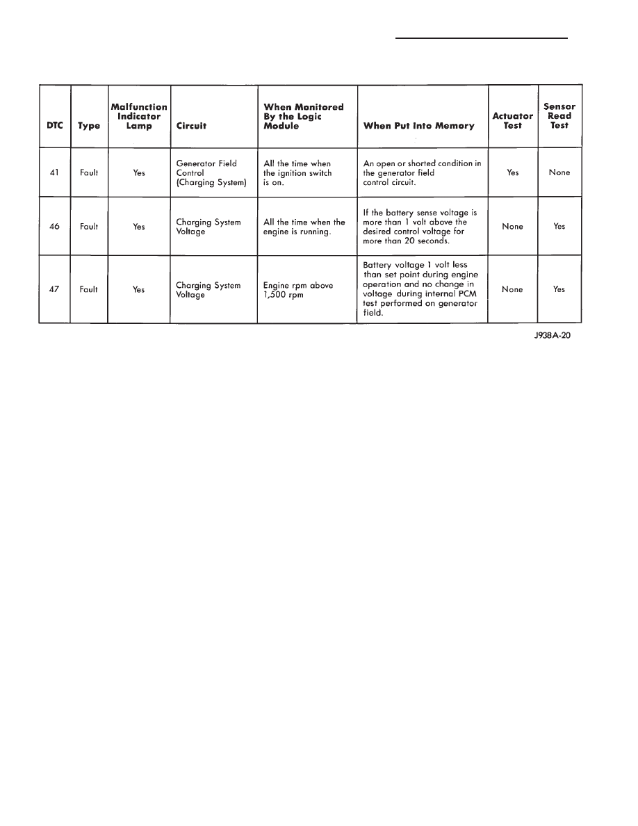
GENERATOR DIAGNOSTIC TROUBLE CODE (DTC)
8A - 20
BATTERY/STARTING/CHARGING SYSTEMS DIAGNOSTICS
Z
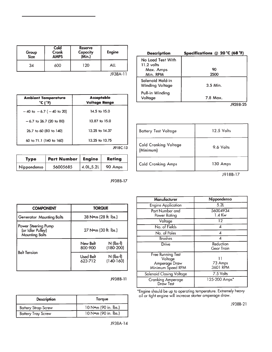
SPECIFICATIONS
4.0L ENGINE
5.2L ENGINE
BATTERY CLASSIFICATIONS AND RATINGS
GENERATOR OUTPUT VOLTAGE SPECIFICA-
TIONS
TORQUE SPECIFICATIONS
TORQUE SPECIFICATIONS
ENGINE STARTER MOTOR AND SOLENOID
TESTING SPECIFICATIONS
ENGINE STARTER MOTOR COLD CRANKING
SPECIFICATIONS
REDUCTION GEAR STARTER
Z
BATTERY/STARTING/CHARGING SYSTEMS DIAGNOSTICS
8A - 21

Document Outline
- ELECTRICAL
- BATTERY/ STARTING/ CHARGING SYSTEMS DIAGNOSTICS
- BATTERY TEST PROCEDURES
- IGNITION OFF DRAW (IOD)
- ENGINE STARTER MOTOR TEST PROCEDURES
- GENERATOR TEST PROCEDURES ON VEHICLE
- SPECIFICATIONS
Wyszukiwarka
Podobne podstrony:
93ZJ Secc 11 Exhaust System and Intake Manifold
93ZJ Secc 8F Audio Systems
93ZJ Secc 8M Restraint Systems
93ZJ Secc 25 Emission Control Systems
93ZJ Secc 8Q Vehicle Theft Security System
93ZJ Secc 8K Windshield Wiper and Washer Systems
93ZJ Secc 8U Chime Buzzer Warning Systems
93ZJ Secc 8H Vehicle Speed Control System
Electronics 4 Systems and procedures S
7 Electrical System
21 body electrical system
How an inverter fits into your solar electric system By Jo
02 engine electrical system
Electrical systems
Electronics 4 Systems and procedures S
7 Electrical System
93ZJ Secc 8J Turn Signals and Hazard Warning Flashes
Self Study Programme 17 Octavia convenience electronic system
więcej podobnych podstron