
VEHICLE SPEED CONTROL SYSTEM
CONTENTS
page
page
SERVICE PROCEDURES
. . . . . . . . . . . . . . . . . . . 9
TEST PROCEDURES
. . . . . . . . . . . . . . . . . . . . . . 5
GENERAL INFORMATION
The vehicle speed control system (Fig. 1) is electri-
cally controlled and vacuum operated. The electronic
control is integrated into the Powertrain Control
Module (PCM). The PCM is located in the engine
compartment on the passenger side dash panel. The
controls are located on the steering wheel and consist
of the ON/OFF, RESUME/ACCEL and SET/DECEL
buttons. The system is designed to operate at speeds
between 35 mph (50 km/h) and 85 mph (142 km/h).
WARNING: THE USE OF VEHICLE SPEED CONTROL
IS NOT RECOMMENDED WHEN DRIVING CONDI-
TIONS DO NOT PERMIT MAINTAINING A CONSTANT
SPEED, SUCH AS IN HEAVY TRAFFIC OR ON
ROADS THAT ARE WINDING, ICY, SNOW COVERED,
OR SLIPPERY.
TO ACTIVATE: By pushing the ON/OFF button to
the depressed latched position, ON, the speed control
function is now ready for use.
TO DEACTIVATE: A soft tap of the brake pedal,
normal brake use or clutch pedal use while the sys-
tem is engaged will disengage speed control without
erasing memory. A sudden increase in engine R.P.M.
may be experienced if the clutch pedal is depressed
while the speed control system is engaged. Pushing
the ON/OFF button to the unlatched position or turn-
ing off the ignition erases the memory.
TO SET SPEED: When the vehicle has reached
the desired speed push the SET/DECEL button to
engage system which will then automatically main-
tain the desired speed.
TO DECELERATE: When speed control is en-
gaged, holding the SET/DECEL button depressed al-
lows the vehicle to coast to a lower speed setting.
TO RESUME: After disengaging the speed control
system by tapping the brake or clutch pedal, push the
RESUME/ACCEL button to return vehicle to the pre-
viously set speed.
TO ACCELERATE: While speed control is en-
gaged, hold the RESUME/ACCEL button depressed
and release at a new desired speed. This will allow
the vehicle to continuously accelerate and set at a
higher speed setting.
TAP-UP: When the speed control system is en-
gaged, tapping the RESUME/ACCEL button will in-
crease the speed setting by 2 mph (3 km/h). The
system will respond to multiple tap-ups.
TO ACCELERATE for PASSING: Depress the ac-
celerator as you would normally. When the pedal is
released the vehicle will return to the speed setting in
memory.
Z
VEHICLE SPEED CONTROL SYSTEM
8H - 1
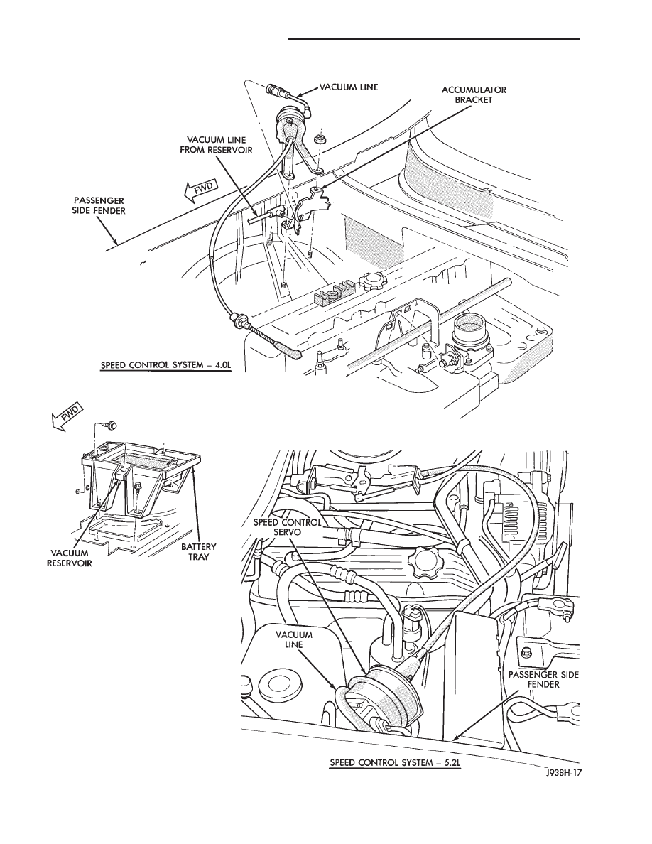
Fig. 1 Vehicle Speed Control System
8H - 2
VEHICLE SPEED CONTROL SYSTEM
Z

Z
VEHICLE SPEED CONTROL SYSTEM
8H - 3
8H - 4
VEHICLE SPEED CONTROL SYSTEM
Z

TEST PROCEDURES
INDEX
page
page
Checking for Diagnostic Trouble Code
. . . . . . . . . . 5
Electrical Tests at Powertrain Control Module
. . . . . 6
Electrical Tests at Servo
. . . . . . . . . . . . . . . . . . . . . 5
General Information
. . . . . . . . . . . . . . . . . . . . . . . . 5
Inoperative System
. . . . . . . . . . . . . . . . . . . . . . . . 5
Road Test
. . . . . . . . . . . . . . . . . . . . . . . . . . . . . . . 5
Stop Lamp Speed Control Switch Test
. . . . . . . . . . 7
Vacuum Supply Test
. . . . . . . . . . . . . . . . . . . . . . . 8
Vehicle Speed Control Switch Test
. . . . . . . . . . . . . 7
Vehicle Speed Control System Electrical Tests
. . . . 5
Vehicle Speed Sensor Test . . . . . . . . . . . . . . . . . . . 5
GENERAL INFORMATION
Before starting diagnosis and repair procedures for
a speed control malfunction, verify that the speed
control wire harness is properly connected to all con-
nectors. Refer to Diagnosis Chart.
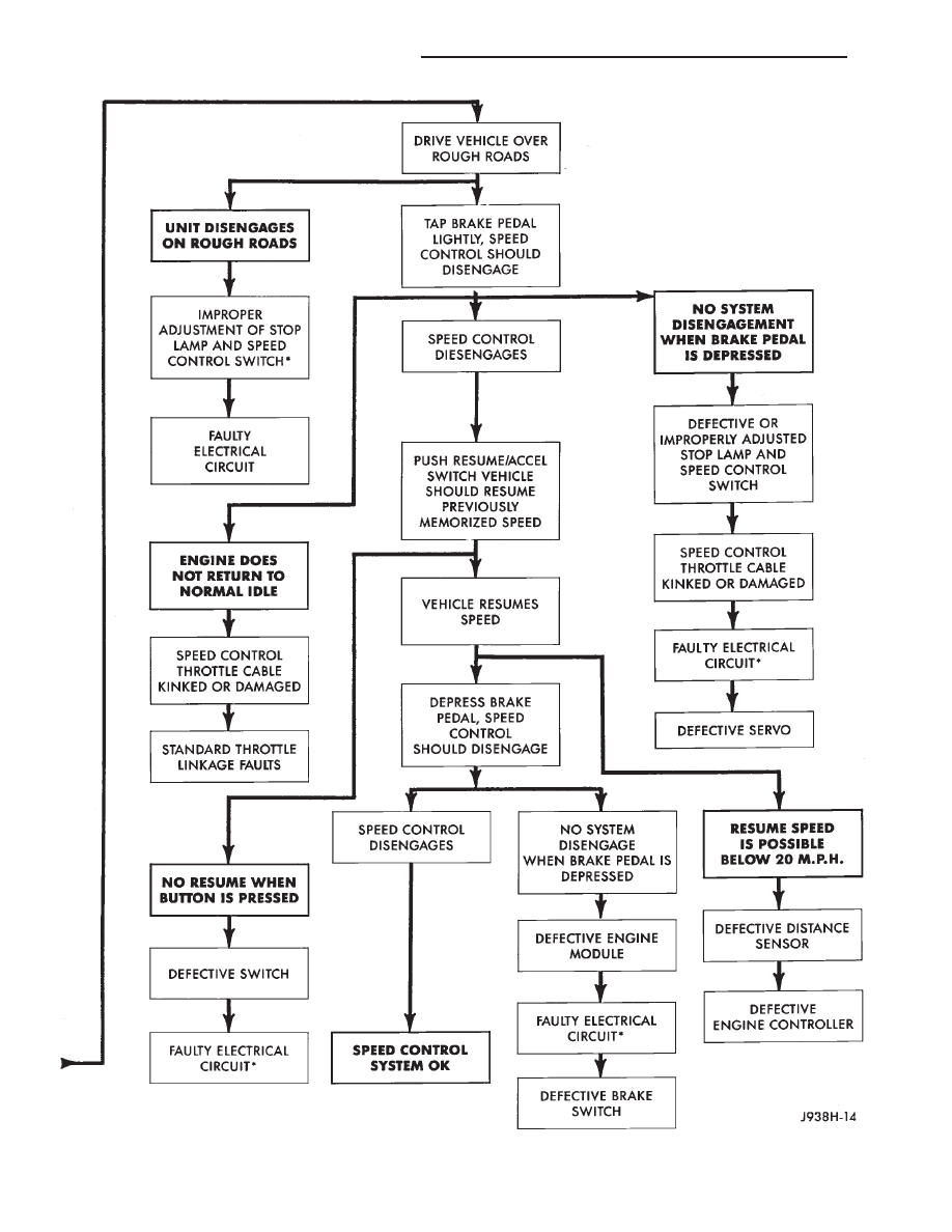
ROAD TEST
Road test vehicle to verify reports of speed control
system malfunction. The road test should include at-
tention to the speedometer. Speedometer operation
should be smooth and without flutter at all speeds.
Flutter in the speedometer indicates a problem
which might cause surging in the speed control sys-
tem. The cause of any speedometer deficiencies
should be corrected before proceeding.
INOPERATIVE SYSTEM
If a road test verifies a system problem and the
speedometer operates properly, check for:
• loose electrical and vacuum connections at the
servo
• correct installation of the vacuum check valve in
the hose from servo to vacuum source. The word VAC
on the valve must point toward the vacuum source
• corrosion that should be removed from electrical
terminals and a light coating of Mopar MultiPurpose
Grease, or equivalent, applied
• secure attachment of both ends of the speed control
cable.
CHECKING FOR DIAGNOSTIC TROUBLE CODE
(1) When trying to verify a speed control system
electrical problem, use a DRB II Scan Tool to find the
cause. Refer to Powertrain Diagnostic Procedures
manual.
If the DRB II is not available, the Diagnostic
Trouble Code (DTC) may be determined with the
following method:
(a) With key inserted in ignition switch, cycle
switch to ON position 3 times. On third cycle, leave
switch in ON position.
(b) After switch has been cycled 3 times, observe
the Malfunction Indicator Lamp ‘‘CHECK EN-
GINE’’ on instrument cluster. If a DTC is present,
the code will be displayed in a series of flashes
representing digits. Three flashes in rapid succes-
sion, a slight pause, then 4 flashes in rapid succes-
sion would indicate DTC 34.
(2) If a DTC 34 is observed, perform the tests in the
sections Electrical Tests at Servo and Electrical Tests
at Powertrain Control Module.
If a DTC 15 is observed, perform the test for a
faulty Vehicle Speed Sensor.
(3) Correct any problems found when performing
these tests and recheck for DTC if changes were
made.
VEHICLE SPEED SENSOR TEST
For testing of the Vehicle Speed Sensor and related
components refer to the Powertrain Diagnostic Proce-
dures manual.
VEHICLE SPEED CONTROL SYSTEM ELECTRICAL
TESTS
Vehicle speed control systems may be tested using
two different methods. One involves use of a DRB II
Scan Tool. If this test method is desired, refer to the
Powertrain Diagnostic Procedures manual.
The other test method uses a voltmeter. The volt-
meter method is described in the following tests.
If any information is needed concerning wiring, re-
fer to the Section 8W - Wiring Diagrams.
CAUTION: When test probing for voltage or continu-
ity at electrical connectors, care must be taken not
to damage connector, terminals, or seals. If these
components are damaged, intermittent or complete
system failure may occur.
ELECTRICAL TESTS AT SERVO
(1) Turn ignition switch to the ON position.
(2) Push the speed control switch to the ON posi-
tion.
(3) Connect the negative lead of a voltmeter to a
good chassis ground near the servo.
(4) Disconnect the 4-way connector going to the
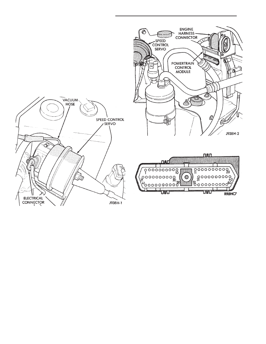
servo (Fig. 2). The blue wire with the green tracer of
the main harness 4-way connector should read ap-
Z
VEHICLE SPEED CONTROL SYSTEM
8H - 5
proximately battery voltage. If not, check for loose
connections, brake switch adjustment or, repair the
main harness as necessary.
(5) Connect a jumper wire between the male and
female terminals of the blue wire with green tracer.
The other 3 male terminals from the servo should
show battery voltage. If not, replace the servo.
(6) Turn ignition OFF. Using an ohmmeter, connect
one lead to a good body ground. Touch the other lead
to the black (BK) wire terminal in the 4-way connec-
tor of the main harness. The meter should show
continuity. If not, repair the ground circuit as neces-
sary.
ELECTRICAL TESTS AT POWERTRAIN CONTROL
MODULE
(1) Unplug 60-way connector from the Powertrain
Control Module, located on the passenger side dash
panel in the engine compartment (Fig. 3).
(2) Connect negative lead of voltmeter to a good
body ground near the module.
(3) For the following tests, the ignition switch must
be in the ON position. Refer to Fig. 4 for control
module terminal locations. Touch the positive lead of
the voltmeter to the terminal in cavity number 33.
With the speed control switch in the OFF position,
the voltmeter should read 0 volts. With the speed
control switch in the ON position, the voltmeter
should read battery voltage. If not, repair the main
harness as necessary.
(4) Touch the positive lead of the voltmeter to the
terminal in cavity number 53. As in step (3), the
voltmeter should read 0 volts with the switch in the
OFF position and battery voltage with the switch in
the ON position.
(5) Touch the positive lead of the voltmeter to the
terminal in cavity number 48. With the speed control
switch in the OFF position, the voltmeter should read
0 volts. With the switch in the ON position, the
voltmeter should read battery voltage. Pressing the
SET button should cause the voltmeter to change
from battery voltage to 0 volts for as long as the
switch is held. If not, perform the speed control
switch test. If the switch is not at fault, then check
the main harness and repair as necessary.
(6) Touch the positive lead of the voltmeter to the
terminal in cavity number 50. The voltmeter should
read 0 volts with the speed control switch in either
the OFF or ON position. With switch in either RE-
SUME or SET position, the voltmeter should read
battery voltage. If not, perform the speed control
switch test. If the switch is not at fault, then check
the main harness and repair as necessary.
Fig. 2 Servo And Harness Connector
Fig. 3 Powertrain Control Module and Connector
Location
Fig. 4 Powertrain Control Module 60-Way Connector
Shown from Terminal End
8H - 6
VEHICLE SPEED CONTROL SYSTEM
Z
(7) Touch the positive lead of the voltmeter to the
terminal in cavity number 49. The voltmeter should
read 0 volts with the switch in the OFF position.
With the switch in the ON position, the voltmeter
should read battery voltage. The voltmeter will con-
tinue to read battery voltage when either the SET or
RESUME switch is pressed. If not, perform the speed
control switch test. If the switch is not at fault, then
check the main harness and repair as necessary.
(8) Turn key OFF. Using an ohmmeter, connect
one lead to a good body ground and touch the other
lead to the terminal in cavity number 29. With the
brake pedal released, the meter should show continu-
ity. When the pedal is depressed, the meter should
show open circuit.
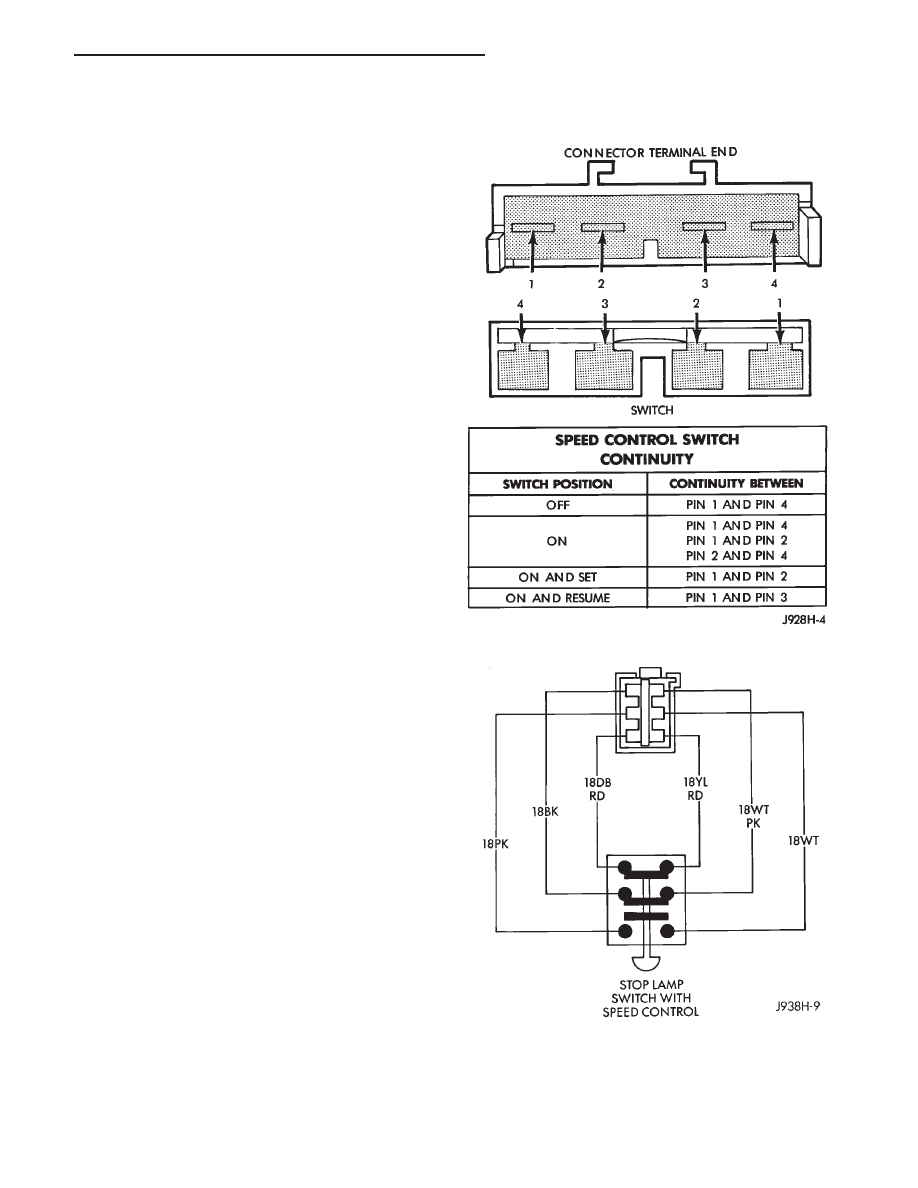
VEHICLE SPEED CONTROL SWITCH TEST
WARNING: BEFORE BEGINNING ANY AIR BAG SYS-
TEM COMPONENT REMOVAL OR INSTALLATION, RE-
MOVE AND ISOLATE THE NEGATIVE (-) CABLE FROM
THE BATTERY. THIS IS THE ONLY SURE WAY TO DIS-
ABLE THE AIR BAG SYSTEM. FAILURE TO DO THIS
COULD RESULT IN ACCIDENTAL AIR BAG DEPLOY-
MENT AND POSSIBLE INJURY.
To check the switch, remove the switch from its
mounting position, refer to Service Procedures -
Speed Control Switch. Use an ohmmeter and refer to
the Switch Continuity Chart to determine if continu-
ity is correct. If there is no continuity at any one of
the switch positions, replace the switch.
STOP LAMP SPEED CONTROL SWITCH TEST
(1) Disconnect the connector at the stop lamp
switch. Using an ohmmeter, continuity may be
checked at the switch side of the connector as follows
(Fig. 5):
(a) With the brake pedal at rest (plunger of
switch pushed in by brake pedal) there should be:
• continuity between the black (BK) and white with
pink tracer (WT/PK) wires
• continuity between the yellow with red tracer (YL/
RD) and dark blue with red tracer (DB/RD) wires.
• NO continuity between the pink (PK) and white
(WT) wires.
(b) With brake pedal depressed, there should be:
• continuity between pink (PK) and white (WT)
wires
• NO continuity between black (BK) and white with
pink tracer (WT/PK) wires
• NO continuity between the yellow with red tracer
(YL/RD) and dark blue with red tracer (DB/RD)
wires.
(2) If the above results are not obtained, the stop
lamp switch is defective or out of adjustment.
Stop lamp switch adjustment is detailed in Group 5
- Brakes.
SPEED CONTROL SWITCH CONTINUITY
CHART
Fig. 5 Stop Lamp Switch Connector
Z
VEHICLE SPEED CONTROL SYSTEM
8H - 7
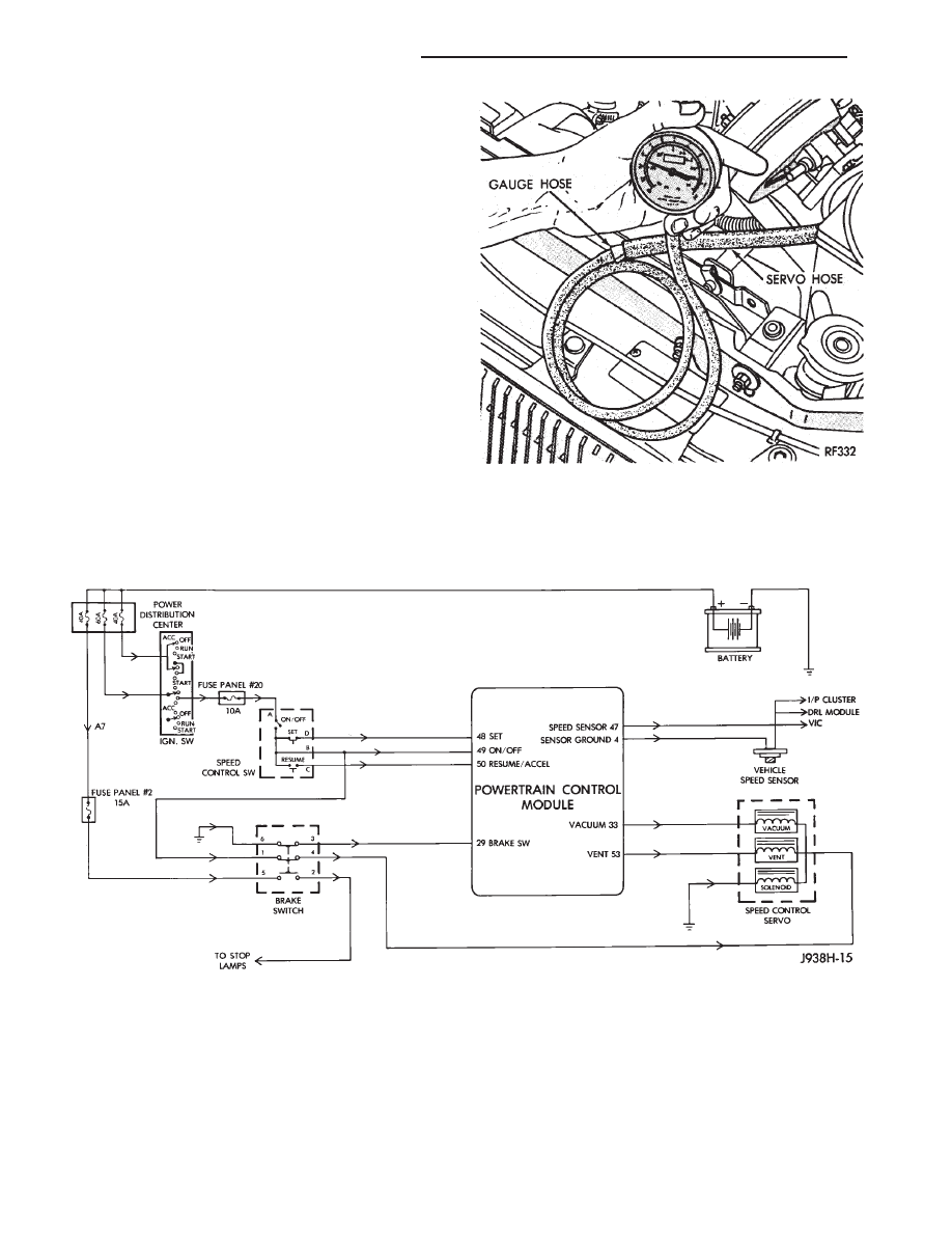
VACUUM SUPPLY TEST
(1) Disconnect vacuum hose at the servo or vac-
uum receiver and install a vacuum gauge in the hose
(Fig. 6).
(2) Start engine and observe gauge at idle. Vac-
uum gauge should read at least 10 inches of mer-
cury.
(3) If vacuum does not meet this requirement,
check for vacuum leaks or poor engine performance.
Fig. 6 Vacuum Gauge Test
VEHICLE SPEED CONTROL SYSTEM SCHEMATIC
8H - 8
VEHICLE SPEED CONTROL SYSTEM
Z
SERVICE PROCEDURES
INDEX
page
page
Servo Cable Replacement
. . . . . . . . . . . . . . . . . . . 9
Servo Unit
. . . . . . . . . . . . . . . . . . . . . . . . . . . . . . . 9
Speed Control Switch . . . . . . . . . . . . . . . . . . . . . . . 9
Vacuum Reservoir
. . . . . . . . . . . . . . . . . . . . . . . . 10
SERVO UNIT
REMOVAL
(1) Disconnect vacuum hose at servo.
(2) Unplug electrical connector at servo.
(3) Remove 2 nuts from servo mounting bracket.
(4) Remove and discard push nuts on servo studs.
(5) Pull servo away from mounting bracket.
(6) Pull speed control cable away from servo to
expose cable retaining clip.
(7) Remove clip attaching cable to servo.
INSTALLATION
(1) With throttle blocked to full open position, align
hole in cable sleeve with hole in servo pin and install
retaining clip.
(2) Insert servo studs through holes in the cable.
(3) Insert servo studs through holes in servo
mounting bracket.
(4) Install new push nuts on the servo studs.
(5) Install the 2 attaching nuts and tighten to 8.5
N
Im (75 in. lbs.).
(6) Connect vacuum hose to servo.
(7) Connect the electrical connector to servo termi-
nals.
SPEED CONTROL SWITCH
WARNING: BEFORE BEGINNING ANY AIR BAG SYS-
TEM COMPONENT REMOVAL OR INSTALLATION,
REMOVE AND ISOLATE THE NEGATIVE (-) CABLE
FROM THE BATTERY. THIS IS THE ONLY SURE WAY
TO DISABLE THE AIR BAG SYSTEM. FAILURE TO
DO THIS COULD RESULT IN ACCIDENTAL AIR BAG
DEPLOYMENT AND POSSIBLE INJURY.
REMOVAL
(1) Disconnect negative cable from the battery.
(2) Remove 2 screws from back side of steering
wheel (Fig. 1).
(3) Rock switch away from horn pad while lifting
switch out of steering wheel.
(4) Disconnect
4-way
electrical
connector
from
clockspring.
INSTALLATION
(1) Connect 4-way electrical connector from clock-
spring to switch.
(2) Place switch in steering wheel, sliding the for-
ward edge of switch under horn pad. Line up locating
pins on switch with holes in steering wheel frame.
(3) Attach switch to wheel with 2 screws starting
with the screw at the left end of the switch.
(4) Connect negative cable to battery.
SERVO CABLE REPLACEMENT
CAUTION: Use finger pressure only to remove the
speed control cable connector at the bell crank.
Pliers or screwdriver can break the connector re-
quiring the complete cable replacement.
(1) Using finger pressure only, remove speed con-
trol cable connector at bell crank by PUSHING con-
nector off the bell crank (Fig. 2). DO NOT try to pull
connector off perpendicular to the bell crank.
(2) Squeeze tabs on speed control cable and push
out of locking plate (Fig. 3).
(3) Pull cable out of cable guide.
(4) Remove 2 nuts, 2 pushnuts, and cable housing
from the servo.
(5) Release the cable clip from the servo cable and
remove the servo cable.
(6) To install, reverse the removal procedure.
Fig. 1 Speed Control Switch Removal
Z
VEHICLE SPEED CONTROL SYSTEM
8H - 9
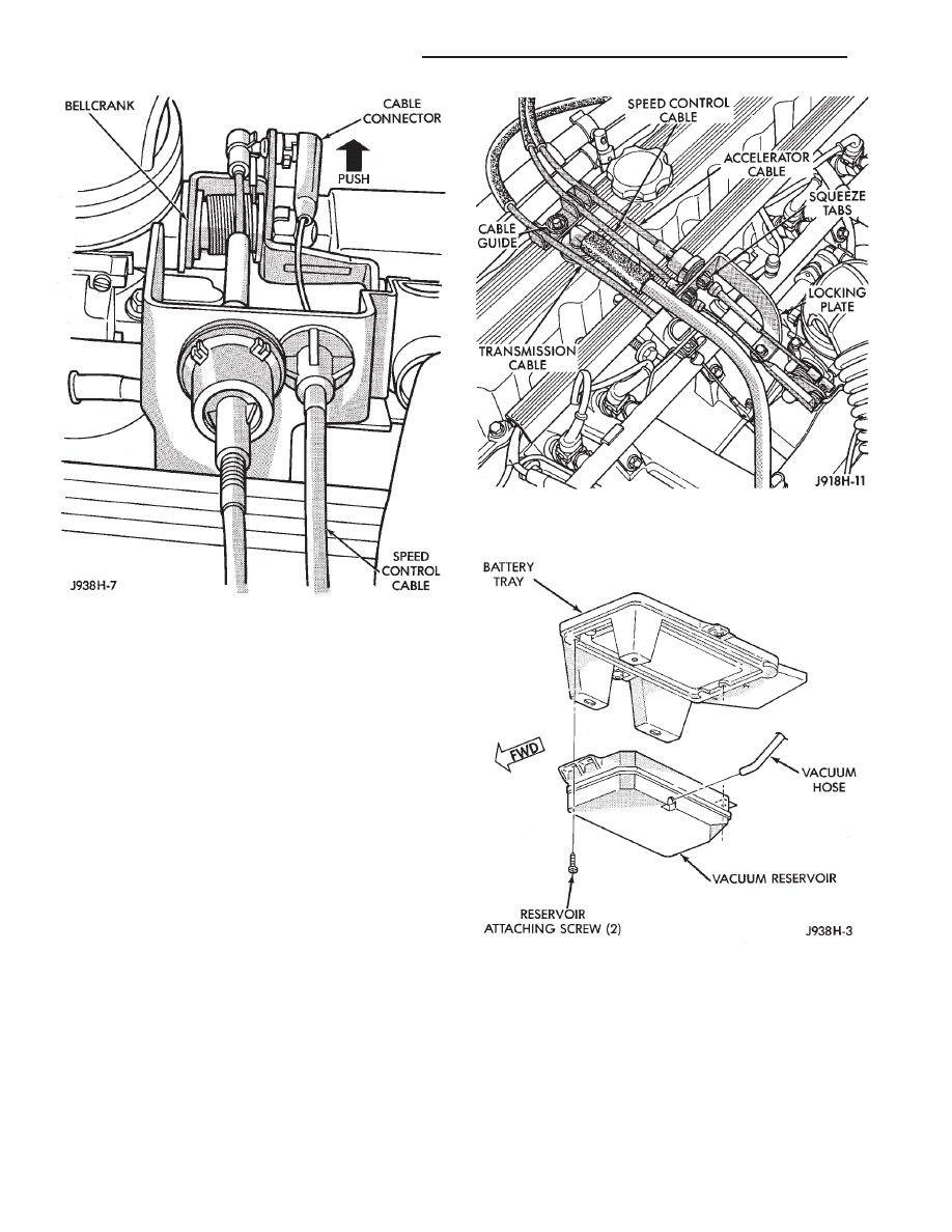
VACUUM RESERVOIR
REMOVAL
(1) Disconnect battery cables, negative cable first.
(2) Remove both battery holddown bolts.
(3) Remove battery from vehicle.
(4) Remove 5 screws holding battery tray.
(5) Pull up battery tray and remove vacuum line
from reservoir (Fig. 4).
(6) Remove 2 screws holding reservoir to battery
tray.
INSTALLATION
(1) Install vacuum reservoir to battery tray.
(2) Connect vacuum line to reservoir.
(3) Install battery tray. Tighten screws to 10 N
Im
(90 in. lbs.).
(4) Install battery.
(5) Install
battery
strap
and
holddown
bolts.
Tighten bolts to 10 N
Im (90 in. lbs.).
(6) Install
battery
cables,
positive
cable
first.
Tighten clamps to 8.5 N
Im (75 in. lbs.).
Fig. 2 Remove Bell Crank Connector
Fig. 3 Remove/Install Speed Control Cable to Lock-
ing Plate
Fig. 4 Vacuum Reservoir
8H - 10
VEHICLE SPEED CONTROL SYSTEM
Z
Document Outline
- VEHICLE SPEED CONTROL SYSTEM
- CONTENTS
- TEST PROCEDURES
- GENERAL INFORMATION
- ROAD TEST
- INOPERATIVE SYSTEM
- CHECKING FOR DIAGNOSTIC TROUBLE CODE
- VEHICLE SPEED SENSOR TEST
- VEHICLE SPEED CONTROL SYSTEM ELECTRICAL TESTS
- ELECTRICAL TESTS AT SERVO
- ELECTRICAL TESTS AT POWERTRAIN CONTROL MODULE
- VEHICLE SPEED CONTROL SWITCH TEST
- STOP LAMP SPEED CONTROL SWITCH TEST
- VACUUM SUPPLY TEST
- SERVICE PROCEDURES
Wyszukiwarka
Podobne podstrony:
96ZJ 8H VEHICLE SPEED CONTROL SYSTEM
93ZJ Secc 8Q Vehicle Theft Security System
93ZJ Secc 8U Chime Buzzer Warning Systems
93ZJ Secc 25 Emission Control Systems
80 Vehicle Control System
80 Vehicle Control System
93ZJ Secc 11 Exhaust System and Intake Manifold
93ZJ Secc 8F Audio Systems
80 Vehicle Control System
93ZJ Secc 8A Electrical Systems
93ZJ Secc 8M Restraint Systems
80 Vehicle Control System
93ZJ Secc 8K Windshield Wiper and Washer Systems
Control System Toolbox
10 Emission control system
07 emission control system
10 Engine Control System
ENGINE CONTROL SYSTEM
530 Speed controllers 1202 EN
więcej podobnych podstron