
Operating Instructions
L
Speed controllers
530 series
EDB530_E/GB
00460234

These operating instructions are valid for controllers with the nameplate
designation
531__ E
.
3A
532__ E
.
3A
533__ E
.
3A
534__ E
.
3A
Controller type
Chassis type
Hardware version + index
Edition of:
05/1996
revised:
12/2002
1
L
How to use this manual ...
To locate information on specific topics, simply refer to the table of contents at
the beginning and to the index at the end of this manual.
The manual uses a series of different symbols to provide quick reference and
to highlight important items.
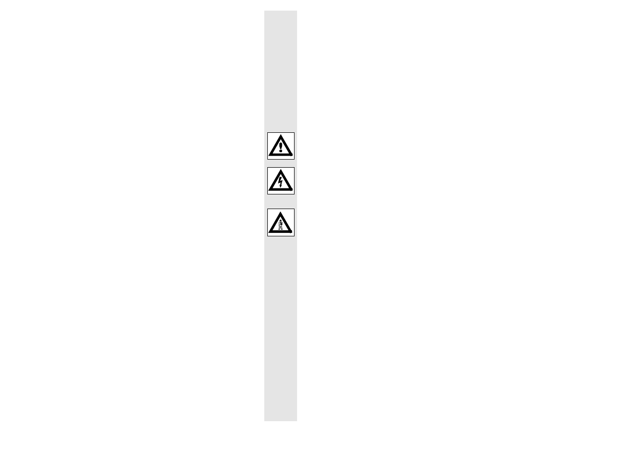
This symbol refers to items of information intended to facilitate operation.
Notes which should be observed to avoid possible damage to or destruction of
equipment.
Notes which should be observed to avoid health risks to the operating
personnel.
2
L
Safety and application notes
for drive controllers
(according to: Low Voltage Directive 73/23/EWG)
1. General
During operation, drive controllers may have, according to their type of
protection, live, bare, in some cases also movable or rotating parts as well as
hot surfaces.
Unauthorized removal of the required cover, inappropriate use, incorrect
installation or operation, creates the risk of severe personal injury or damage to
material assets.
Further information can be obtained from the documentation.
All operations concerning transport, installation, and commissioning as well as
maintenance must be carried out by qualified, skilled personnel (IEC 364
and CENELEC HD 384 or DIN VDE 0100 and IEC report 664 or DIN VDE 0110
and national regulations for the prevention of accidents must be observed).
Qualified skilled personnel according to this basic safety information are
persons who are familiar with the erection, assembly, commissiong, and
operation of the product and who have the qualifications necessary for their
occupation.
2. Application as directed
Drive controllers are components which are designed for installation into
electrical systems or machinery.
When installing into machines, commissioning of the drive controllers (i.e. the
starting of operation as directed) is prohibited until it is proven that the machine
corresponds to the regulations of the EC directive 89/392/EWG (Machinery
Directive); EN 60204 must be observed.
Commissioning (i.e. starting of operation as directed) is only allowed when
there is compliance with the EMC Directive (89/336/EWG).
The drive controllers meet the requirements of the Low Voltage Directive
73/23/EWG. The harmonized standards of the prEN 50178/ DIN VDE 0160
series together with EN 60439-1/DIN VDE 0660 part 500 and EN 60146/DIN
VDE 0558 are applicable to drive controllers.
The technical data and information about the connection conditions must be
obtained from the nameplate and must be observed in all cases.
3. Transport, storage
Notes for transport, storage and appropriate handling must be observed.
Climatic conditions must be observed according to prEN 50178.

3
L
4. Erection
The devices must erected and cooled according to the regulations of the
corresponding documentation.
The drive controllers must be protected from inappropriate loads. Particularly
during transport and handling, components must not be bent and/or insulation
distances must not be modified. Touching of electronic components and
contacts must be avoided.
Drive controllers contain electrostatically sensitive components which can
easily be damaged by inappropriate handling. Electrical components must not
be damaged or destroyed mechanically (health risks are possible!).
5. Electrical connection
When working on live drive controllers the valid national regulations for the
prevention of accidents (e.g. VBG 4) must be observed.
The electrical installation must be carried out according to the appropriate
regulations (e.g. cable cross-sections, fuses, PE connection). More detained
information is included in the documentation.
Notes concerning the installation in compliance with EMC - like screening,
grounding, arrangement of filters and laying of cables - are included in the
documentation of the drive controllers. These notes must also be observed in
all cases for drive controllers with the CE mark. The compliance with the
required limit values demanded by the EMC legislation is the responsibility of
the manufacturer of the system or machine.
6. Operation
Systems where drive controllers are installed must be equipped, if necessary,
with additional monitoring and protective devices according to the valid safety
regulations, e.g. law on technical tools, regulations for the prevention of
accidents, etc. Modifications of the drive controllers and the operating software
are prohibited.
After disconnecting the drive controllers from the supply voltage live parts of the
controller and power connections must not be touched immediately because of
possibly charged capacitors. For this, observe the corresponding labels on the
drive controllers.
During operation, all covers and doors must be closed.
7. Maintenance and servicing
The manufacturer´s documentation must be observed.
This safety information must be preserved!
The product specific safety and application notes in these operating
instructions must also be observed!

4
L
Contents
1
Features of the 530 series of controllers
5
2
Technical data
6
2.1
Controller-specific data
6
2.2
Dimensions
7
2.3
Scope of supply
8
2.4
Application as directed
8
3
Accessories
9
4
Installation
13
4.1
Installation
13
4.2
Connection
13
4.2.1
Installation corresponding to EMC
16
4.2.2
CE-typical drive system
17
4.3
Connecting voltage
20
4.4
Replacing the fuses
21
4.5
Connection diagram
22
5
Setting
24
5.1
Selection of the current range for type 534
24
5.2
Setting the current limit
25
5.3
Speed setting
25
6
Operating modes
27
6.1
Switching operation
27
6.1.1
Controller enable
27
6.1.2
Controller inhibit
27
6.2
Electrodynamic braking
28
6.3
Reversing
30
Index
31

5
l
1
Features of the 530 series of controllers
The 530 series of controllers series comprises 4 half-controlled single-quadrant
controllers with output powers from 0.36 kW to 2 kW for the operation of DC
shunt or permanent magnet motors.
•
Compact single-board controllers for space-saving installation on a mounting
plate or DIN rail 35 x 7.5 mm
•
Easy connection through screwless, vibration-proof plug and socket
connectors
•
Protective cover prevents accidental contact of live components
•
Operation with tacho or armature voltage feedback with "I x R compensation"
•
Operational integrity even under mains voltage fluctuations and short-term
mains failure because of static and dynamic voltage monitoring
•
Interference immunity from bad mains wave-form because of synchronizing
filter and channel separation of the firing pulses
•
Compliance with the EC directive for the design of a CE-conform drive
system
6
L
2
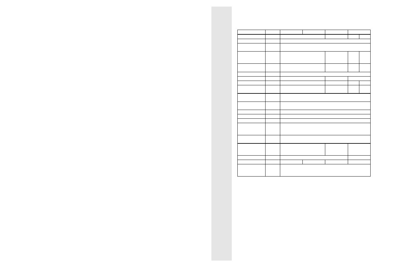
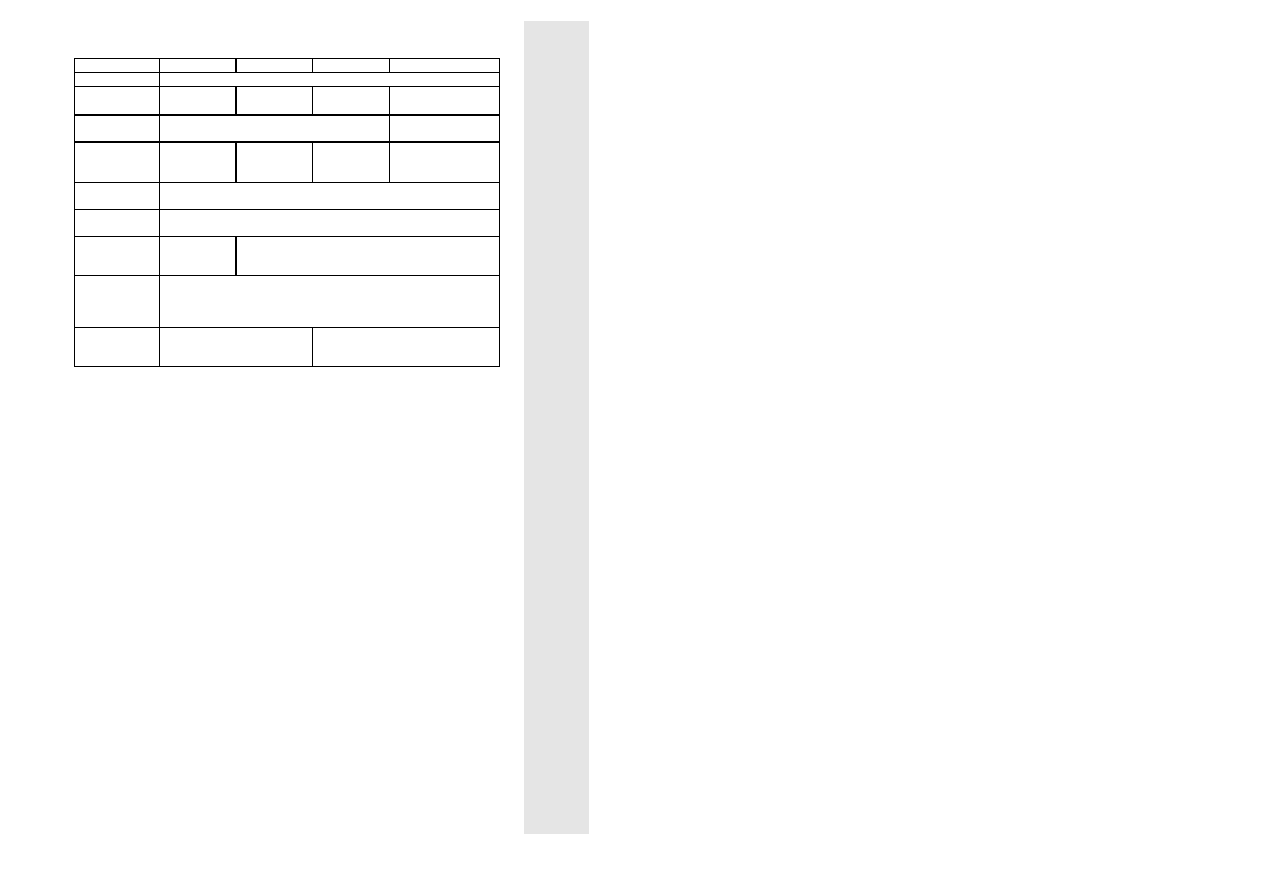
Technical data
2.1
Controller-specific data
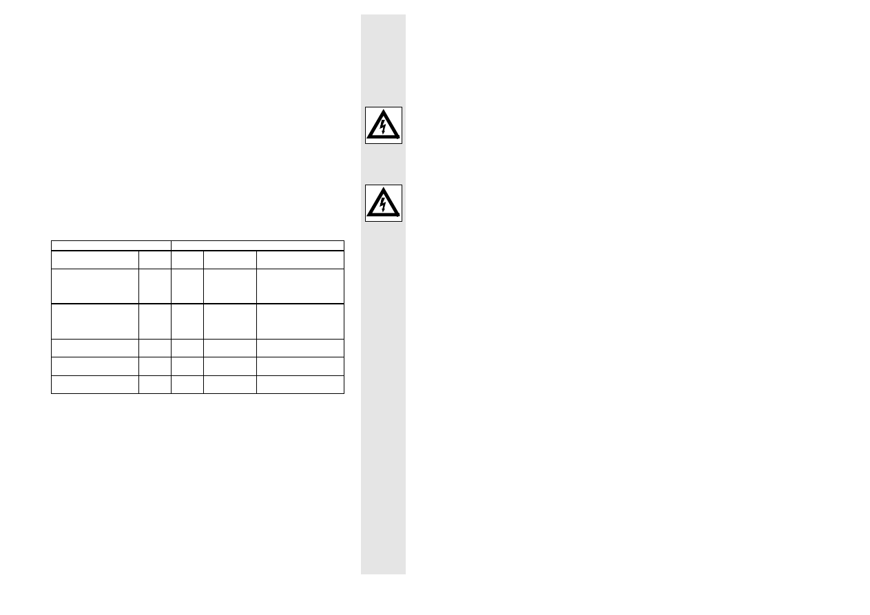
Controller
531
532
533
534
Output power
P
el
[W]
360
720
1360
2040
Mains frequency
f [Hz]
50...60
Mains voltage
U
L1, N
[V]
190...265
(100...132 with solder link)
Armature current
(can be changed
for 534)
I
Amax
[A]
2
4
8
12
Armature voltage
for V
L1, N
= 230 V
V
A
[V]
180
180
180
170
Field voltage
V
F
[V]
0.9 x U
L1,
⋅N
Max. field current
I
Fmax
[A]
0.3
0.6
1.5
Perm. form factor F
Fmax
1.4
1.4
1.6
1.2
I
⋅ R
compensation
R
A
[
Ω]
0...20
0...10
0...5
0...2.5
Rated master
voltagae
V
LN
[V]
10
Rated tacho
voltage
V
TN
[V]
10...120
Acceleration time T
i
[s]
1...10
Min. speed
n
min
[n
N
]
0...0.25
Max. speed
n
max
[n
N
]
0.75...1
Ambient
temperature
during operation
T
a
[°C]
0...45
Set-value pot.
type
10k
Ω / 1W
lin.
ER00322194
Fuse
type
FF6.3 / 250V
EFSFF0063ASA
FF8 / 250V
EFSFF0080A
SA
FF20 / 250 V
EFSFF0200A
SB
Weight
m [kg]
0.4
1.2
Chassis type E
33.531_E
33.532_E
33.533_E
33.534_E
Operating
instructions
type
EDB0530/D/GB
7
l
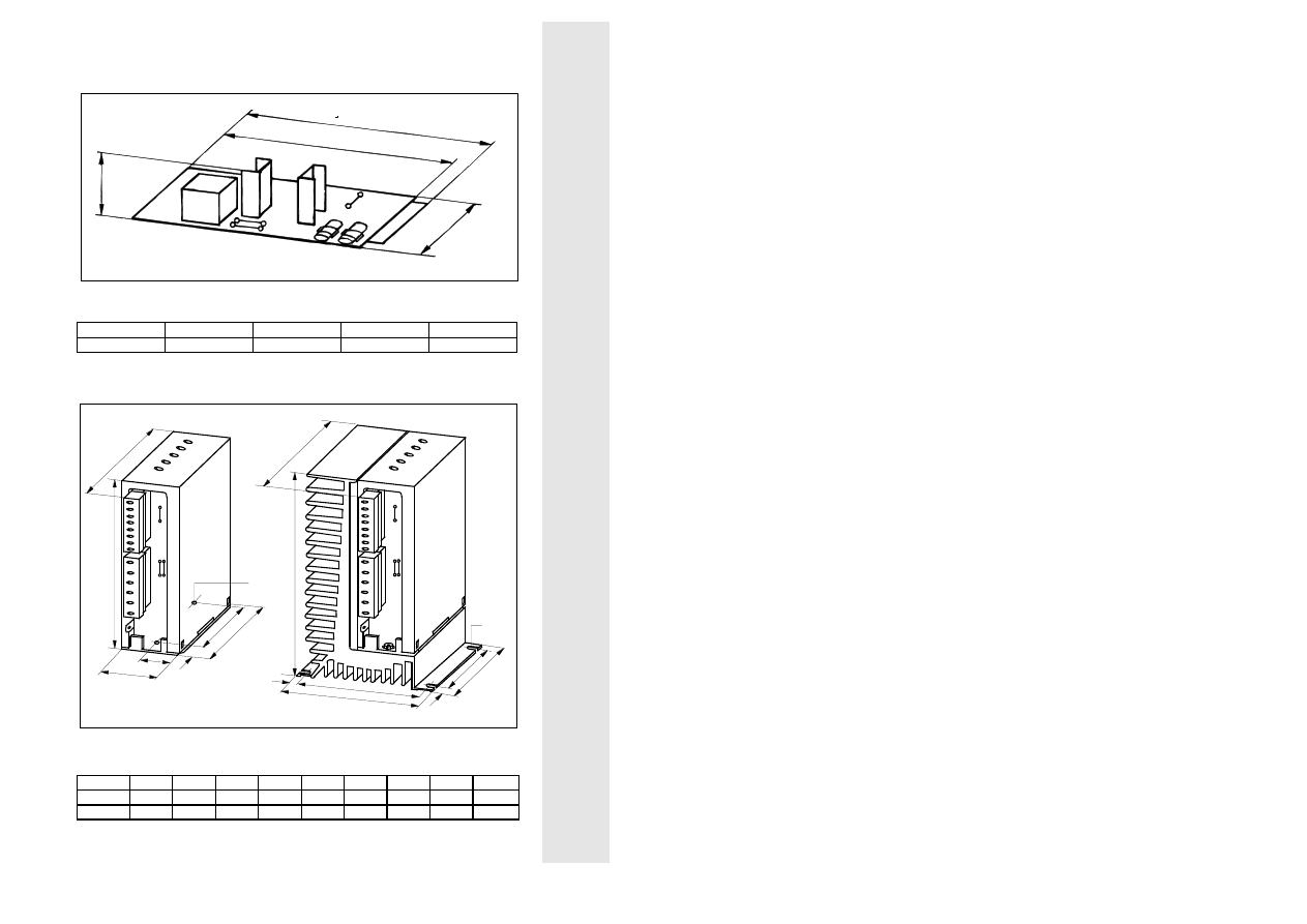
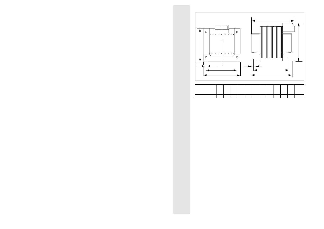
2.2
Dimensions
Type 531
1)
2)
a
b
c
d
1)
Jumper "BR1", "BR2" (change 230 V / 120 V)
2)
Jumper "BR3" (n
max
setting)
Type
a [mm]
b [mm]
c [mm]
d [mm]
531
35
160
150
100
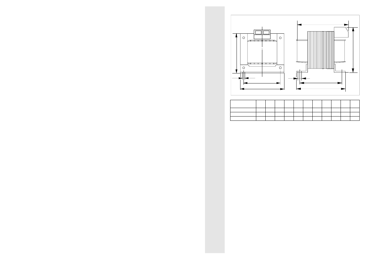
Types 532 and 533
Type 534
a
b
c
d
e
f
g
∅
2)
1)
h
IxR
L 530
T
i
n
min
max
n
I
max
a
b
c
d
e
2)
1)
∅
f
g
IxR
I
max
L 530
max
n
n
min
T
i
1)
Jumper "BR1", "BR2" (change 230 V / 120 V)
2)
Jumper "BR3" (n
max
setting)
Type
a [mm] b [mm] c [mm] d [mm] e [mm] f [mm] g [mm] h [mm]
∅
∅
∅
∅ [mm]
532, 532
120
109
95
7
22.5
45
127
-
4.5
534
120
109
95
7
88
100
150
6
4.5

8
L
2.3
Scope of supply
The scope of supply includes:
•
the controller 53x_E
•
the operating instructions
•
the set-value potentiometer 10 k
Ω
•
plug-in terminals
2.4
Application as directed
•
The controllers of the types 53x are electrical equipment for installation into
control cabinets of electrical systems or machinery.
•
The controllers of the types 53x are designed as components for the control
of speed-variable drives with separately-excited DC motors or for the
assembly with other components to form a machine or system.
•
Drive systems with drive controllers 53x which are installed according to the
definition of a CE-typical drive system (see chapter 4.2.2), correspond to the
EC EMC Directive and the standards mentioned below.
CE-typical drive systems are
- suitable for the operation on public and non-public mains and
- provided for industrial applications.
•
Because of the ground potential reference of the RFI filters, the CE-typical
drive system which is described is not suitable for the connection to IT mains
(mains without ground potential reference).
•
The drive controllers are not domestic appliances, but they are designed for
drive systems for commercial use.
•
The controllers of the types 53x themselves are not machines according to
the EC Machinery Directive. The final function is only determined when
integrated into the machine construction of the user.
•
The user must consider measures in his machine construction which limit the
consequences in case of malfunction or failure of the drive controller
(increase of the motor speed or sudden motor stop) so that hazards for
persons or material assets cannot be caused, such as:
− further independent equipment for the monitoring of safety-relevant
variables (speed, travel, end positions, etc.)
− electrical or non-electrical protective equipment (latching or mechanical
blocking)
− measures covering the complete system
9
l
3
Accessories
Type
531
532
533
534
Armature choke
Suitable types depend on motor type
Mains choke
Type
−
−
−
−
−
−
2.5 mH, 18 A
ELN1_0250H018
RFI filter
Type
EZF1_004A001
EZF1_01812A001
Spring kit for DIN
rail 15 mm
Type
−
EJ00329026
−
EJ00329061
Knob for pot.
Type
ER00308273
Scale for pot.
Type
ER00308274
Support for plug-
in boards
Type
EJ00304817
−
Interference
suppression
module
Typ
EZ00341588
Zinc-oxide
varistor
Type
S20 K275
307 957
B32 K275
308 935
10
L
Mains choke
a
f
c
m
k
e
d
b
n
Mains choke for
type 534
L
[mH
]
I
[A]
a
[mm
]
b
[mm
]
c
[mm
]
d
[mm
]
e
[mm
]
f
[mm
]
k
[mm
]
m
[mm
]
n
[mm
]
Weigh
t
[kg]
ELN1_0250H018
2.5
18
96
77
84
61
96
87
90
5.5
9
2.4
11
l
RFI filter (V
max
= 250 V ±0 %)
a
b
d
e
f
g
c
h
Design A
e
d
b
c
f
a
Design B
Types
Filter
[Type]
Desi
gn
a
[mm
]
b
[mm
]
c
[mm
]
d
[mm
]
e
[mm
]
f
[mm
]
g
[mm
]
h
[mm
]
Fixing
531...53
3
EZF1_004A001
A
91.5
70
40
51
63.5
30
33
60.4
2 x M4
534
EZF1_018A001
B
116
85
39
108
50.8
100
-
-
4 x M6
12
L
Armature choke
a
f
c
m
k
e
d
b
n
Armature choke
L
[mH]
I
[A]
a
[mm]
b
[mm]
c
[mm]
d
[mm]
e
[mm]
f
[mm]
k
[mm]
m
[mm]
n
[mm]
ELK_440H004
40
4,4
104
82
84
66
100
92
100
5.8
11
ELK_500H002
50/15 2/10
120
100
90
84
107
103
115
5.8
11
ELA_400H010
40/12 10/18 150
122
121
101
130
132
140
7.0
13
The suitable type of armature choke depends on the motor type.

13
l
4
Installation
4.1
Installation
The chassis-type controller is to be installed in a vertical position, with the
terminals at the bottom, to ensure sufficient cooling and air circulation. The
ambient temperature mut not exceed +45°C.
Unwanted voltages fed back from the controllers to the supply mains are
reduced by the connection of mains chokes and RFI filters. The components
allocated to type 53x are listed in chapter 3 "Accessories".
4.2
Connection
•
The controllers contain electrostatically sensitive components. Prior to
assembly and servicing the personnel must be free of electrostatic charges.
Discharging is possible by touching the PE fixing scew or another grounded
metal part in the control cabinet.
•
If you use residual current devices:
− The controllers have an internal mains rectifier. After a short-circuit to
frame a DC fault current may prevent the tripping of the residual current
device. Therefore, take additional measures like zeroing or use universal
current e.l.c.b.
− Observe for the dimensioning of the release current of e.l.c.b. that
capacitive compensating currents of the cable screens and RFI filters
occuring during normal operation may cause false tripping.
− Note for the use of universal e.l.c.b.:
The preliminary standard prEN50178 (in the past VDE0160) about the use
of universal e.l.c.b. has been decided by the German committee K226.
The final decision about the use in compliance with the standard is made
by the CENELEC/CS (European Committee for Electrotechnical
Standardization) in Brussels. Further information on the use of universal
current e.l.c.b. can be obtained from the supplier.
14
L
•
The plug connector is suitable for the connection of solid wire or single or
multi-strand conductors of cross-sections between 0.14 and 2.5 mm². The
length of the free wire should be between 8 and 9 mm. It is not necessary to
use ferrules.
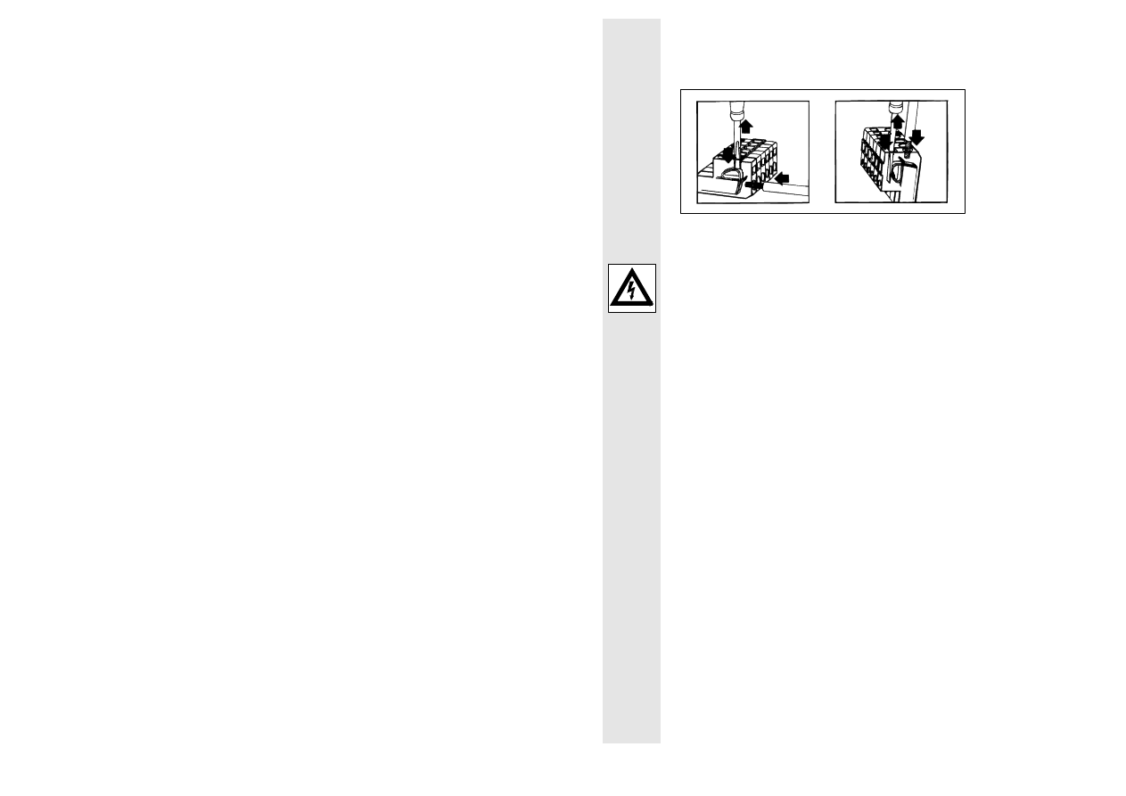
1
2
3
1
2
3
Before removing the protective cover, switch-off the controller and remove the
connectors.
Warning
All controller terminals carry mains potential. It is therefore necessary that
all input and output signals required for the control of the controller are,
electrically, safely separated by measures outside the controller and have
another protection against direct contact (double basic insulation).
When using the supplied set-value potentiometer the mechanical fixing
must have an additional PE connection and the connections must be
insulated and covered.
Prior to commissioning make sure that there is no earth fault in the connecting
cables. The protective conductor must only be connected to the PE connection
(6.3-mm spade connector). PE or ground connections to any other terminals
cause a controller failure.
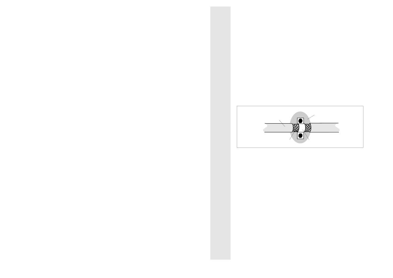
Screen motor cables A, B, I and K as well as the control cables. The screen
must be connected at both ends to the central PE connection. The control
cables must not be longer than 10 m. Check the voltage rating of the screened
cable.
To ensure that the screening is effective, it should not be opened or interrupted.
It should also be laid as close as possible at the cable ends. Connect the
screening of the motor cables to PE in the motor terminal box.
15
l
If the cable between RFI filter and controller is longer than 200 mm, use
screened mains cables. The ground chassis connection should have as low a
resistance and as large a surface as possible.
Type 53x can be used for operation with armature voltage or tacho feedback
(see chapter 4.5 "Connecting diagram").
In case of armature voltage control with "I x R compensation" insert a jumper
between terminal 2 and terminal 4.
Caution!
At terminals 2/4 and 3/4 only the feedback system used must be
connected.
For master voltage operation remove the set-value potentiometer and apply the
master voltage across terminal 7 (-) and terminal 8 (+).
Caution!
The master voltage must be free of mains and ground potential. Several
controllers can only be operated from a master voltage when they are
electrically isolated.
Note for the connection of controller and motor
Lenze controller
Motor (acc. to DIN 42017 / VDE 0530 part 8)
Function
Terminal Terminal other
designations
Motor type
Armature voltage
+
-
Excitation voltage
+
-
A
B
I
K
1B1
2B2
F1
F2
A1
B2, A2
E1
E2
DC motor uncompensated
with commutating pole
winding
Armature voltage
+
-
Excitation voltage
+
-
A
B
I
K
1C1
C2
F1
F2
A1
C2
E1
E2
DC motor compensated
with commutating pole
winding
Armature voltage
+
-
A
B
A1
A2
Permanent magnet motor
DC tacho
+
-
3
4
2A1
2A2
AC tacho
+
with rectification
-
3
4
3A1
3A2

16
L
4.2.1 Installation corresponding to EMC
•
Controllers cannot be operated on their own. The EMC of controllers on their
own cannot be tested. Only the integration of the controllers into a drive
system allows a test whether the objectives of the EC EMC Directive are met
and whether the device are in compliance with the law about the
electromagnetic compatibility of equipment.
•
Lenze has done conformity tests with the controllers of the types 53x in
certain, defined drive systems. These tested drive systems are called "CE-
typical drive system" in the following.
•
Therefore, the user of the controller has the choice,
− either to determine the system components and their integration into a
drive system himself and to determine the conformity under his own
responsibility
− or to install the drive system according to the CE-typical drive system as
tested by the manufacturer of the controller and declared to be in
compliance.
•
If you observe the following measures you can assume that EMC problems
caused by the drive system will not arise during the operation of the machine
and the EMC Directive and the EMC law are satisfied.
•
For any other installation, e.g.
− use of unscreened cables,
− use of collective RFI filters instead of the allocated RFI filters,
− omission of mains chokes
the machine or system must be tested whether it is compliance with the EC
EMC Directive and the EMC limit values are considered.
•
The compliance with the EMC Directive in the machine application is
the responsibility of the user.
17
l
4.2.2 CE-typical drive system
Components of a CE-typical drive system
System components
Specification
Controller
Controller of the types 531 to 534
RFI filter
Data and allocation see chapter 3 "Accessories"
Mains choke
Data and allocation see chapter 3 "Accessories"
Armature and field cable
Screened power cable with tinned E-CU braid with
85 % optical coverage.
Tested maximum length: 50 m
Mains cable between RFI filter and
mains choke and between mains
choke and controller
As from cable length of 200 mm:
screened power cable with tinned E-CU braid with
85 % optical coverage.
Control cables
Screened signal cable type LIYCY
Motor
DC motor with separate excitation
Lenze series GFQ, GFR or similar
Note:
Controller, RFI filter, and mains choke are located on one mounting plate.
Installation of the CE typical drive system
The electromagnetic compatibility of a drive system depends on the type and
accuracy of the installation.
Take special care with
− filters
− screening
− grounding
Filters
•
Only use the RFI filters and mains chokes allocated to the controllers (see
chapter 3 "Accessories").
−
RFI filters reduce non-permissible high-frequency interferences to a
permissible value.
−
Mains chokes reduce low-frequency interference which depends primarily
on the motor cables and their length.
For motor cables which are longer than 50 m additional measures are
required.
Screening
•
Screen all cables from and to the controller.
•
Make sure that motor cables are separated from signal and mains cables
when laying the cables.
•
Avoid a common terminal board for mains input and motor output.
•
The cables must be laid as close as possible to the reference potential.
Dangling cables are like antennas.
18
L
Grounding
•
Ground all conductive metal components (controllers, RFI filters, mains
chokes) by suitable cables from a central grounding point
(PE bar).
•
Observe the minimum cross-sections prescribed in the safety information.
However, for EMC the surface of the contact is important and not the cross-
section.
Assembly
•
Make a contact from controller, RFI filter, and mains chokes to the grounded
mounting plate with as large a surface as possible. Zinc-coated mounting
plates allow long-lasting contacts. For painted plates the paint of the
mounting plates must be removed in all cases.
•
If you use several mounting plates:
−
Make a conductive connection of the mounting plates with as large a
surface as possible (e.g. using copper bands).
•
Connect the screen of the armature and field cable to the mounting plate with
as large a surface as possible:
−
Recommendation: Make the large-surface connection of the screens to the
mounting plate with earthing clamps on bare metal mounting surfaces.
•
If there are contactors, motor protection switches, or terminals in the
armature cable:
−
Contact of the screens of the connected cables to each other and to the
mounting plate with as large a surface as possible.
•
In the terminal box, connect the screen of the motor to PE:
−
Metal cable glands at the motor terminal box ensure a large-surface
connection of the screen to the motor housing.
•
If the total length of the mains cable between RFI filter and mains chokes and
controller exceeds 200 mm:
−
Screen mains cables
−
Connect the screen of the mains cables to the mounting plate with as large
a surface as possible.
•
Connect the screen of the control cables to the mounting plate with as large a
surface as possible.
19
l
Part of the CE-typical drive system which is located on the mounting plate
Mains choke
LOAD
LINE
PE
RFI filter
L1 N Connection mains fuse
Paint-free bare metal
contact surface
Paint-free
surfaces for
screen
contact
Paint-free surface
for screen contact
PE bar
PE connection
Mounting plate
conductive
connection
with PE
Controller
PE
Screened
field and
armature cable
Connect screen of the
motor cables at the motor
side as well with a large
surface to PE
Screened
control cables
L
1)
1)
The mains choke is only necessary for type 534.
20
L
4.3
Connecting voltage
As a standard, the controller is factory-set for the operation on a mains voltage
from 190 to 265 V ±0 %. For a mains voltage from 100 to 132 V ±0 % replace
jumper "BR1" with "BR2".
Caution!
This modification must only be carried out by qualified skilled personnel
when no voltage is applied. After replacing the jumpers the protective
cover must be reassembled.
L
N
T1-B
T1-C
T1-A
BR1
BR2
1
3
5
7
9
10
6
230V / 120V
0,9VA
EI 30
21
l
4.4
Replacing the fuses
The fuses protect the controller from non-permissible operating conditions.
After the operation of such a protective function, the controller and the system
must be checked for further faults before replacing the fuses.
For the replacement of the fuses remove the protective cover and disconnect
the connectors.
Caution!
Removal of the protective cover and the replacement of the fuses must
only be carried out by qualified skilled personnel when no voltage is
applied.
Defective fuses must only be replaced by the prescribed type (see chapter 2.1
"Controller-specific data").
The protective cover must be attached again after the fuses are replaced.
22
L
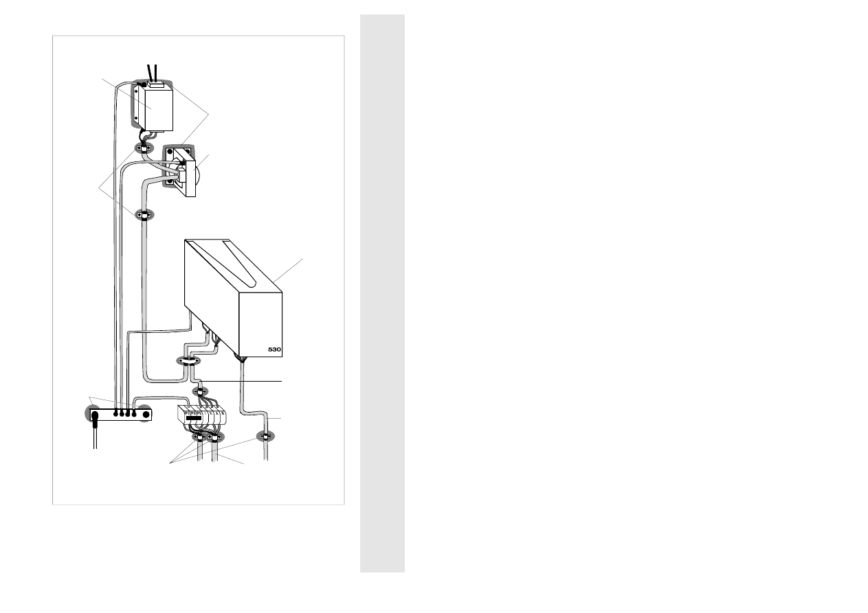
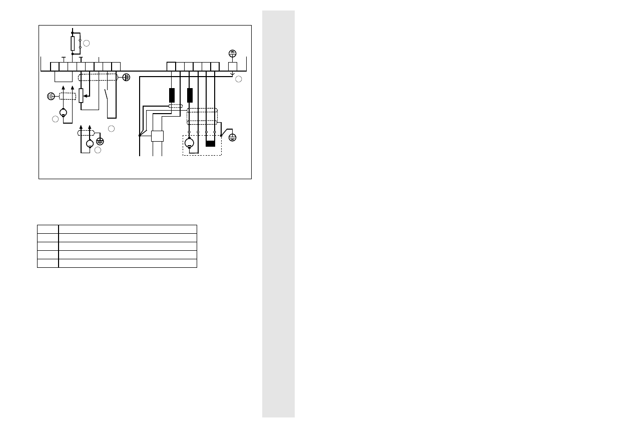
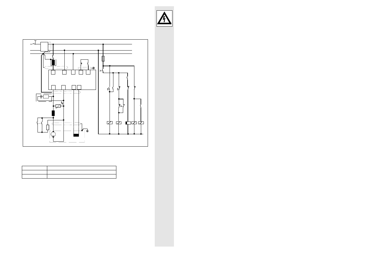
4.5
Connection diagram
Type 531
PE
L1 N
RFR
+V
CC
1
2
U
TN
= 10...120 V
M
N
L1
K
2
3 4
16 17
I
B
A
9
8
7
I
K
A
B
PE
G
+
-
Filter
PE
2)
3
190...265V~ 50 / 60 Hz
(100...132 V~ 50 / 60 Hz)
1)
4
5
A
S
E
n
soll
R=10 k
Ω
lin.
+
-
G
1)
see chapter 4.3 "Connecting voltage"
2)
standard component
Explanations
➀
Coded part
➁
Jumper "BR 3"
➂
Actual value tachogenerator
➃
Controller enable
➄
Master voltage
Note:
If the signals must be changed over via relays, use suitable relay contacts (e.g.
gold-plated contacts).
23
l
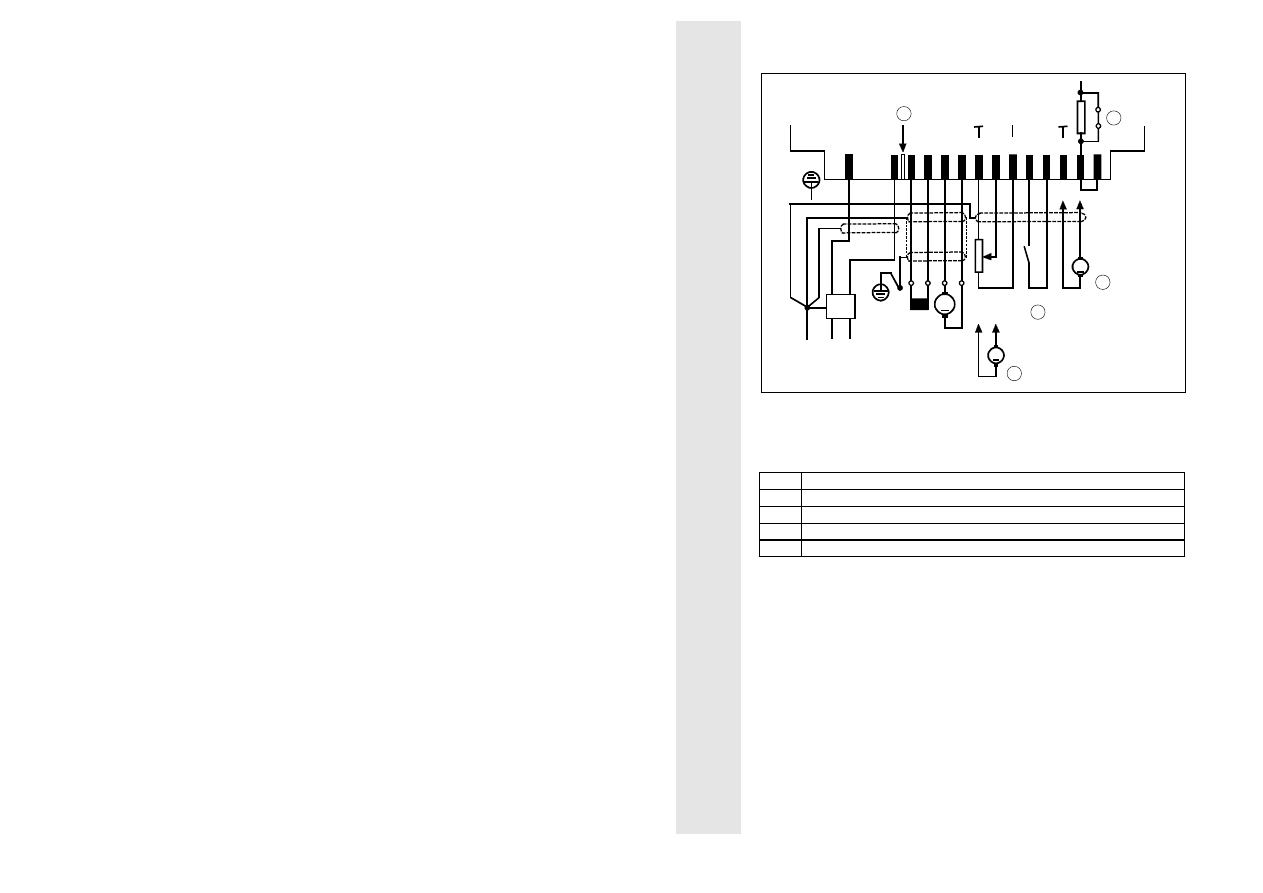
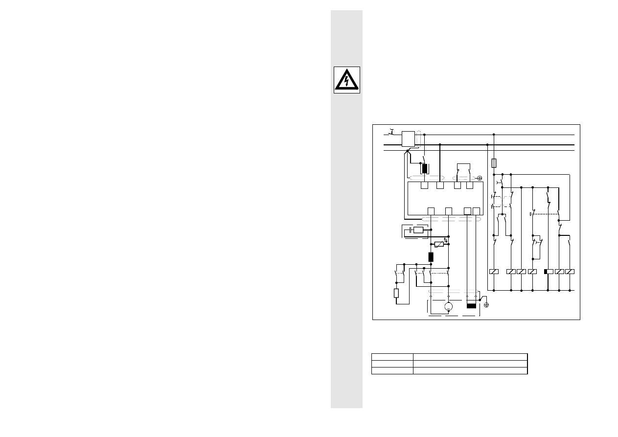
Types 532, 533, 534
N
K
I
B
A
L
PE
L
D
M
N
A
E
RFR
G
+
-
+V
CC
L
K
L
PE
1
2
3
4
8
9
16 17
7
2
2)
G
+
-
5
4
3
U
LN
= 10 V
I
K
A
B
PE
Filter
190...265V~ 50 / 60 Hz
(100...132 V~ 50 / 60 Hz)
1)
S
U
TN
= 10...120 V
n
soll
R = 10 k
Ω
lin.
3)
1)
see chapter 4.3 "Connecting voltage"
2)
standard component
3)
only required for type 534
Explanations
➀
Jumper "BR3"
➁
6.3-mm spade connector
➂
Controller enable
➃
Master voltage
➄
Actual value tachogenerator
Note:
If the signals must be changed over via relays, use suitable relay contacts (e.g.
gold-plated contacts).
24
L
5
Setting
Turn trimmers "I x R", "n
max
", "n
min
", "T
i
" and set-value potentiometer fully
counterclockwise. Trimmer "I
max
" is factory set to rated controller current.
The current range selector for type 534 is factory set to 8 A.
5.1
Selection of the current range for type 534
The current range of type 534 can be set to 12 A by switching off the controller
and moving selector S1 from position 8 A to position 12 A.
Selector S1
12 A
8 A
Caution!
The current range must only be set by qualified skilled personnel when no
voltage is applied.
25
l
5.2
Setting the current limit
Setting the current limit is only required if the maximum output current must be
reduced.
•
Turn trimmer "I
max
" fully counterclockwise and "n
min
" fully clockwise.
•
Connect a moving coil ammeter into the armature circuit to measure the
current.
•
Disconnect the field or stall the motor
(observe the current capacity of the motor during standstill!).
•
For armature voltage control, remove jumper between terminals 2 and 4.
•
Connect mains, close switch "RFR". Turn "I
max
" clockwise to set the
armature current.
•
To calculate the value to be set, divide the rated armature current (see
nameplate) by the form factor (I
AN
/ F
F
).
The permissible rated controller current must not be exceeded.
•
Then disconnect the mains, turn "n
min
" fully counterclockwise, connect the
field and for armature voltage control, reconnect the jumper between
terminals 2 and 4.
5.3
Speed setting
•
For armature voltage control with "I x R compensation" insert jumper
between terminals 2 and 4 as shown in the connecting diagram.
•
For speed control with tacho feedback remove jumper between terminals
2 and 4. Connect the tachogenerator (see connecting diagram).
For rated tacho voltages > 40 V the setting range of the "n
max
" trimmer can
be improved by removing jumper "BR3" (see chapter 4.5 "Connecting
diagram" and chapter 2.2 "Dimensions").
Caution!
The jumper "BR3" must only be removed by qualified skilled personnel
when no voltage is applied.
In case of uncontrolled acceleration of the motor during speed setting,
immediately open switch "RFR". In this case, either the tachogenerator
feedback is missing or has incorrect polarity.

26
L
After checking and correcting the wiring, commissioning can be started again.
•
Switch on the mains and close switch "RFR". Turn the set-value
potentiometer to maximum or set the master voltage to V
LN
= 10 V.
Turn trimmer "n
max
" clockwise until the desired maximum motor speed is
achieved.
•
Turn set-value potentiometer fully counterclockwise or set master voltge to 0
V.Turn trimmer "n
min
" clockwise until the desired minimum motor speed is
achieved.
•
If the minimum speed is to be zero, turn trimmer "n
min
" counterclockwise
until the motor has just stopped running in order to avoid dead movement of
the set-value potentiometer in the low speed range.
Check the setting of the maximum speed because n
min
and n
max
influence
on each other.
•
For armature voltage control with "I x R compensation" the motor speed
loss under load is compensated by turning trimmer
"I x R" clockwise.
Set trimmer "I x R" at low speed until the minimum speed change between
idle running and rated load is achieved. Then, check the setting at higher
speed and the maximum speed setting.
27
l
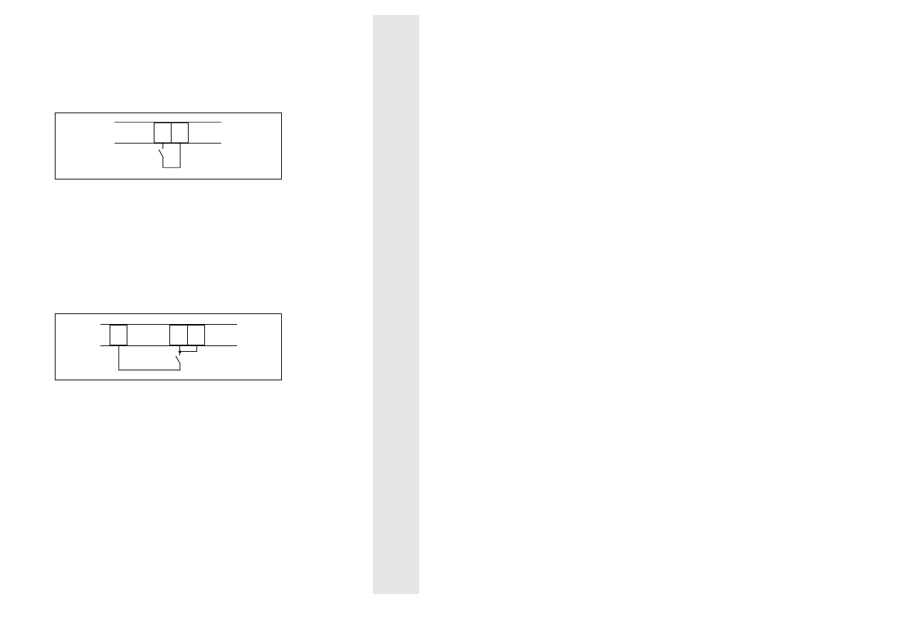
6
Operating modes
6.1
Switching operation
6.1.1 Controller enable
If switch "RFR" is closed, the controller is enabled.
If the switch "controller enable" (RFR) is open, the firing pulses are blocked and
the controller is reset.
RFR
16 17
Note:
Only use low-current contacts for the switching of signal cables
(20 V / 1 mA)
6.1.2 Controller inhibit
The function "RSP", i.e.g the inhibiting of the controller with a normally-open
contact is possible using the following connection.
When "RSP" (controller inhibit) is closed, the firing pulses are blocked and the
controller is reset.
RSP
16 17
7
Note:
Only use low-current contacts for the switching of signal cables
(20 V / 1 mA)

28
L
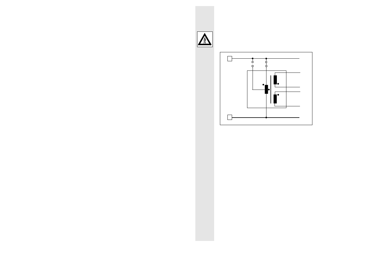
6.2
Electrodynamic braking
If the field is excited, the induced armature current is used for braking the
motor. Before connecting the brake resistor, the controller is inhibited. The
timer relay must be set such that the braking contactor only opens after the
motor has stopped.
Dimensioning of the brake resistor R
B
Neglecting the armature feedback for a required initial braking torque M
Ba
, the
initial braking current I
ABa
results in:
I
I
ABa
AN
=
⋅
M
M
Ba
N
I
AN
= Rated armature current
M
N
= Rated torque
M
Ba
= Initial braking torque
The braking resistor R
B
is calculated as follows:
R
B
=
⋅
U
I
Aa
A
ABa
η
2
U
Aa
= Armature voltage in the motor mode
I
ABa
= Initial braking current
η
A
= Armature efficiency
η
π
A
A A
M n
U
I
=
⋅ ⋅
⋅
2
U
A
= Armature voltage
I
A
= Armature current
M
= Torque
n
= Speed
The size of the brake resistor depends on the braking energy of the drive and
the number of brakings. The braking current should not be more than twice the
rated armature current and should not exceed the maximum starting current.
29
l
To limit the switching voltage peaks, a zinc oxide varistor (R
U
) must be
connected in parallel to the controller output.
For long motor cables (> 50 m) or motors which are connected in parallel, it
may be necessary to use an interference suppression module (see chapter 3
"Accessories")
Braking circuit:
1)
Interference suppression module
2)
Mains choke is only required for type 534
Explanations
K1, K2, K5
Relay
S1
On
S2
Stop
30
L
6.3
Reversing
Reversing is obtained by changing the armature polarity. The motor is
electrodynamically braked to standstill. The braking time must be set at the
timer relay such that the motor is safely at standstill before the armature is
reversed (for dimensioning of the brake resistor see chapter 6.2
"Electrodynamic braking").
To limit the switching voltage peaks, a zinc oxide varistor (R
U
) must be
connected in parallel to the controller output.
For long motor cables (> 50 m) or motors which are connected in parallel, it
may be necessary to use an interference suppression module (see chapter 3
"Accessories")
Reversing circuit:
1)
Interference suppression module
2)
Mains choke is only required for type 534
Explanations
K5, K6, K7
Relay
S2
CW rotation
S3
CCW rotation

31
l
Index
A
Accessories 9
Application
as directed 8
B
Braking
Electrodynamic 28
C
Controller features 5
Controller-specific data 6
D
Dimensions 7
Armature choke 12
Mains choke 10
RFI filter 11
E
EC declaration of conformity
CE-typical drive system 17
I
Installation 13
Connecting diagram 22
Connecting voltage 20
Connection 13
Installation 13
O
Operating modes 27
Controller enable 27
Controller inhibit 27
Electrodynamic braking 28
Reversing 30
R
Replacing the fuses 21
Reversing 30
S
Safety information 2
Scope of supply 8
Setting
Select current range 24
Setting the current limit 25
Speed 25

32
L
Wyszukiwarka
Podobne podstrony:
22 ZF 6 Speed Transmission Parts EN
Variable Speed Control Of Wind Turbines Using Nonlinear And Adaptive Algorithms
96ZJ 8H VEHICLE SPEED CONTROL SYSTEM
G 2 0 DOHC Idle Speed Control Actuator doc
Curtis Series Electronic Motor Speed Controller 1204x 1205x
EZX R Speed Control Manual [Search Manual Online Com]
93ZJ Secc 8H Vehicle Speed Control System
overview simatic controllers 04 2007 en plc
Control Issues Of A Permanent Magnet Generator Variable Speed Wind Turbine
overview simatic controllers 04 2007 en plc
Datasheet BlueSolar charge controller MPPT 75 50 & MPPT 100 50 EN
Need for Speed Porsche Unleashed Manual Win EN
Need for Speed High Stakes Manual Win EN
Lqg Multiple Model Control Of A Variable Speed Pitch Regulated Wind Turbine
2002 Sensorless vector control of induction motors at very low speed using a nonlinear inverter mode
Manual BlueSolar charge controller MPPT 75 50 EN NL FR DE ES SE A6
więcej podobnych podstron