1
AN023
1-888-INTERSIL or 321-724-7143
|
Copyright
©
Intersil Corporation 1999
Low Cost Digital Panel Meter Designs and
Complete Instructions for LCD and LED Kits
Introduction
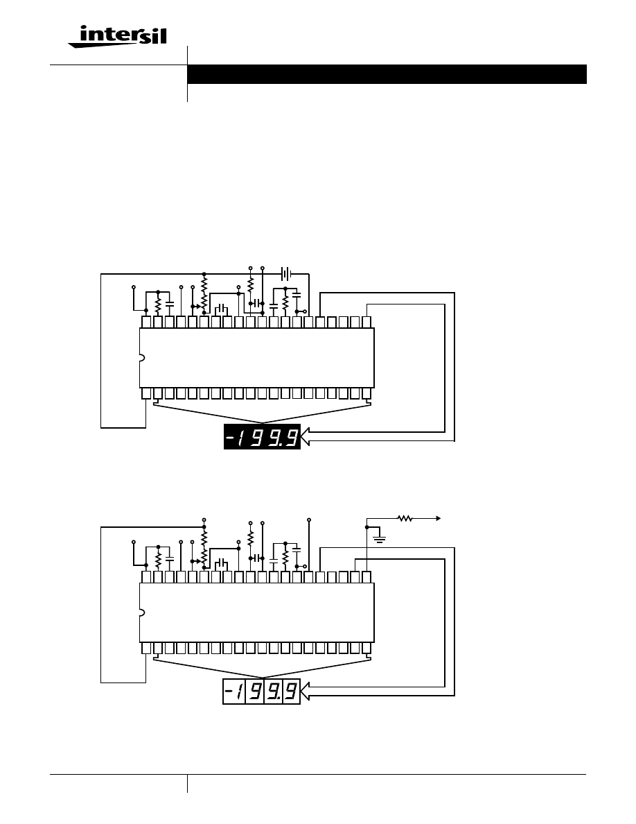
The ICL7106 and ICL7107 are the first ICs to contain all the
active circuitry for a 3
1
/
2
digit panel meter on a single chip.
The ICL7106 is designed to interface with a liquid crystal
display (LCD) while the ICL7107 is intended for light-emitting
diode (LED) displays. In addition to a precision dual slope
converter, both circuits contain BCD to seven segment
decoders, display drivers, a clock and a reference. To build a
high performance panel meter (with auto zero and auto
polarity features) it is only necessary to add display, 4
resistors, 4 capacitors, and an input filter if required (Figures
1 and 2).
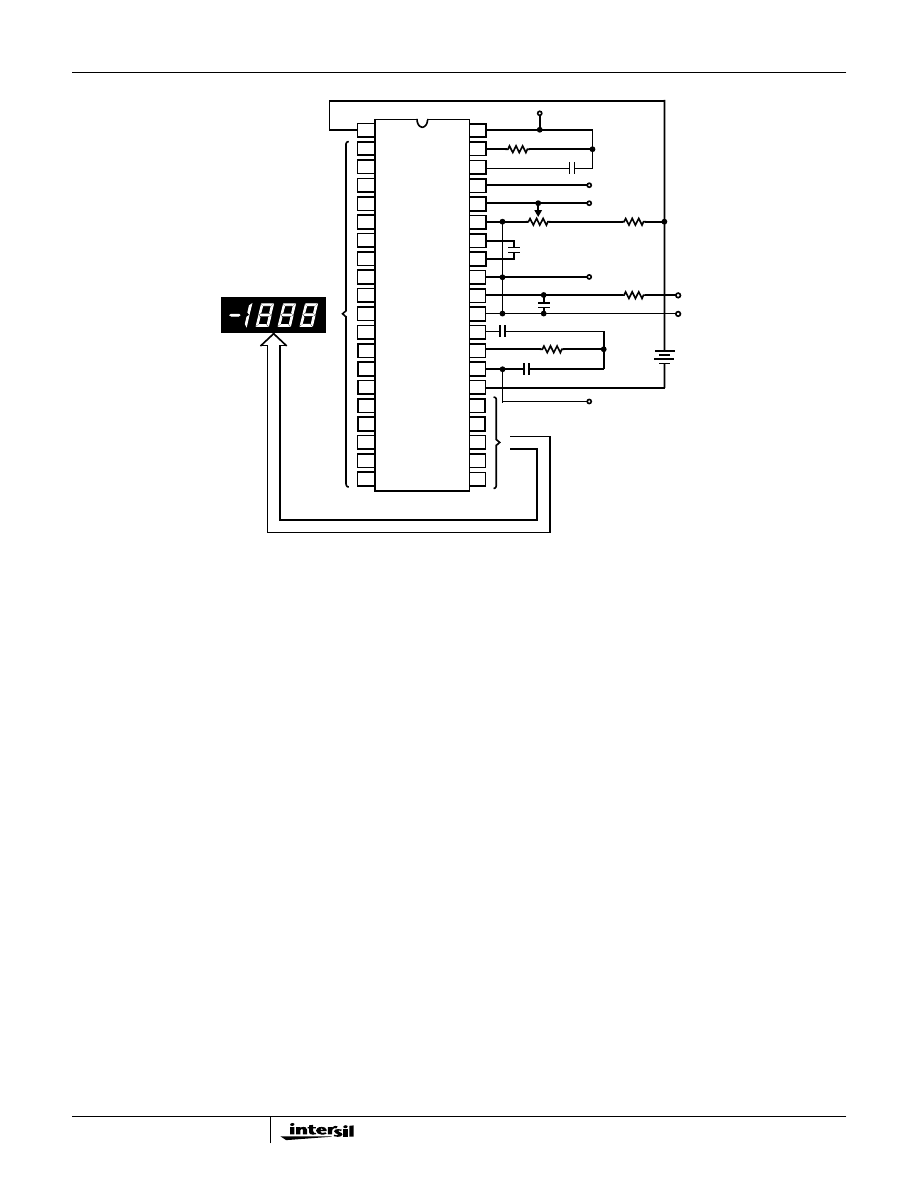
The ICL7136 is an ultra low power version of the ICL7106.
Except for the passive component values as shown in Figure
3 and Table 1, all references in this document to the ICL7106
also apply to the ICL7136.
FIGURE 1. LCD DIGITAL PANEL METER USING ICL7106
FIGURE 2. LED DIGITAL PANEL METER USING ICL7107
13
1
2
3
4
5
6
7
8
9
10
11
12
14
15
16
17
18
19
20
28
40
39
38
37
36
35
34
33
32
31
30
29
27
26
25
24
23
22
21
V+
D1
C1
B1
A1
F1
G1
E1
D2
C2
B2
A2
F2
E2
D3
B3
F3
E3
AB4
POL
OSC 1
OSC 2
OSC 3
TEST
REF HI
REF LO
C
REF
+
C
REF
-
COM
IN HI
IN LO
A-Z
B
UFF
INT
V-
G2
C3
A3
G3
BP
DISPLAY
DISPLAY
C
1
C
2
C
3
C
4
R
3
R
1
R
4
C
5
+
-
IN
R
5
R
2
9V
ICL7106
C
1
= 0.1
µ
F
C
2
= 0.47
µ
F
C
3
= 0.22
µ
F
C
4
= 100pF
C
5
= 0.01
µ
F
R
1
= 24k
Ω
R
2
= 47k
Ω
R
3
= 100k
Ω
R
4
= 1k
Ω
TRIMPOT
R
5
= 1M
Ω
+
-
TP5
TP1TP2
TP3
TP4
13
1
2
3
4
5
6
7
8
9
10
11
12
14
15
16
17
18
19
20
28
40
39
38
37
36
35
34
33
32
31
30
29
27
26
25
24
23
22
21
V+
D1
C1
B1
A1
F1
G1
E1
D2
C2
B2
A2
F2
E2
D3
B3
F3
E3
AB4
POL
OSC 1
OSC 2
OSC 3
TEST
REF HI
REF LO
C
REF
+
C
REF
-
COM
IN HI
IN LO
A-Z
B
UFF
INT
V-
G2
C3
A3
G3
GND
DISPLAY
DISPLAY
C
1
C
2
C
3
C
4
R
3
R
1
R
4
C
5
+
-
IN
R
5
R
2
C
1
= 0.1
µ
F
C
2
= 0.47
µ
F
C
3
= 0.22
µ
F
C
4
= 100pF
C
5
= 0.01
µ
F
R
1
= 24k
Ω
R
2
= 47k
Ω
R
3
= 100k
Ω
R
4
= 1k
Ω
TRIMPOT
R
5
= 1M
Ω
TP5
TP1TP2
TP3
TP4
ICL7107
+5V
-5V
R
6
TO DECIMAL
POINT
R
6
= 150
Ω
Application Note
2
The Evaluation Kits
After purchasing a sample of the ICL7106 or the ICL7107,
the majority of users will want to build a simple voltmeter.
The parts can then be evaluated against the data sheet
specifications, and tried out in the intended application.
However, locating and purchasing even the small number of
additional components required, then wiring a breadboard,
can often cause delays of days or sometimes weeks. To
avoid this problem and facilitate evaluation of these unique
circuits, Intersil offers a kit which contains all the necessary
components to build a 3
1
/
2
digit panel meter. With the help of
this kit, an engineer or technician can have the system “up
and running” in about half an hour.
Two kits are offered, ICL7106EV/KIT and ICL7107EV/KIT.
Both contain the appropriate IC, a circuit board, a display
(LCD for ICL7106EV/KIT, LEDs for ICL7107EV/KIT), passive
components, and miscellaneous hardware.
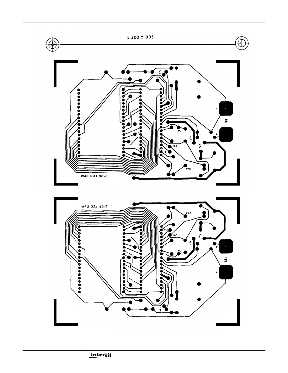
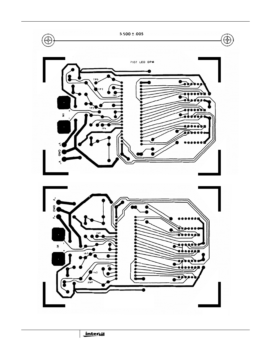
Assembly Instructions
The circuit board layouts and assembly drawings for both
kits are given in Figures 10, 11. The boards are single-sided
to minimize cost and simplify assembly. Jumpers are used to
allow maximum flexibility. For example, provision has been
made for connecting an external clock (Test Point #5).
Provision has also been made for separating REF Lo from
COMMON when using an external reference zener. In a
production instrument, the board area could be reduced
dramatically. Aside from the display, all the components can
easily be placed in less than 4 square inches of board
space.
Molex™ pins are used to provide a low cost IC socket; one
circuit board can thus be used to evaluate several ICs.
(Strips of 20 pins should be soldered onto the PC boards;
the top of the strip holding the pins together can then be
broken off by bending it back and forth using needle-nose
pliers.) Solder terminals are provided for the five test points,
and for the
±
5V input on the ICL7107 kit.
Full Scale Reading - 200mV or 2.000V?
The component values supplied with the kit are those
specified in the schematics of Figure 1 or Figure 2. They
have been optimized for 200mV full scale reading. The
complete absence of last digit jitter on this range illustrates
the exceptional noise performance of the ICL7106 and
ICL7107. In fact, the noise level (not exceeded 95% of time)
is about 15
µ
V, a factor of 10 less than some competitive one
chip panel meters.
To modify the sensitivity for 2.000V full scale, the integrator
time constant and the reference should be changed by
substituting the component values given in Table 1. The
auto-zero capacitor (C
2
) should also be changed. These
additional components are not supplied in the kits. In
addition, the decimal point jumper should be changed so the
display reads 2.000.
FIGURE 3. LCD DIGITAL PANEL METER USING ICL7136
13
1
2
3
4
5
6
7
8
9
10
11
12
14
15
16
17
18
19
20
28
40
39
38
37
36
35
34
33
32
31
30
29
27
26
25
24
23
22
21
OSC 1
OSC 2
OSC 3
TEST
REF HI
REF LO
C
REF
C
REF
COMMON
IN HI
IN LO
A-Z
BUFF
INT
V -
G2
C3
A3
G3
BP
50pF
0.1
µ
F
0.01
µ
F
1M
Ω
180k
Ω
10k
Ω
220k
Ω
IN
+
-
9V
180k
Ω
0.047
µ
F
DISPLAY
+
-
V+
D1
C1
B1
A1
F1
G1
E1
D2
C2
B2
A2
F2
E2
D3
B3
F3
E3
AB4
POL
C
4
R
3
TP5
TP2
R
4
R
1
TP1
C
1
TP3
C
5
R
5
0.01
µ
F
C
2
C
3
R
2
TP4
DISPLAY
Application Note 023
Molex® is a registered trademark of Molex Incorporated.
3
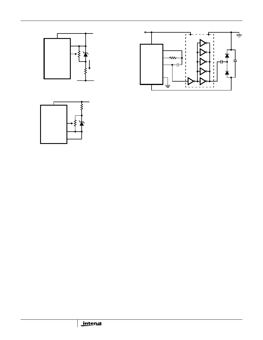
Liquid Crystal Display (ICL7106)
Liquid crystal displays are generally driven by applying a
symmetrical square wave to the Back Plane (BP). To turn on
a segment, a waveform 180
o
out of phase with BP (but of
equal amplitude) is applied to that segment. Note that
excessive DC voltages (>50mV) will permanently damage
the display if applied for more than a few minutes. The
ICL7106 generates the segment drive waveform internally,
but the user should generate the decimal point front plane
drive by inverting the BP (pin 21) output (Note 1). In
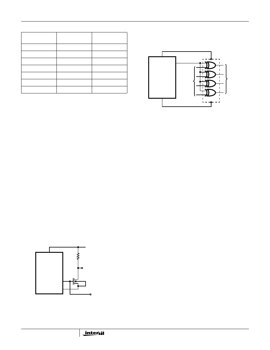
applications where the decimal point remains fixed, a simple
MOS inverter can be used (Figure 4). For instruments where
the decimal point must be shifted, a quad exclusive OR gate
is recommended (Figure 5). Note that in both instances,
TEST (pin 37, TP1) is used as V- for the inverters. This pin is
capable of sinking about 1mA, and is approximately 5V
below V+. The BP output (pin 21) oscillates between V+ and
TEST.
NOTE:
1. In some displays, a satisfactory decimal point can be achieved by
tying the decimal front plan to COMMON (pin 32). This pin is
internally regulated at about 2.8V below V+. Prolonged use of
this technique, however, may permanently burn-in the decimal,
because COMMON is not exactly midway between BP high and
BP lo.
Before soldering the display onto the circuit board, make
sure that it is inserted correctly. Many LCD packages do not
have pin #1 marked, but the segments of an unenergized
display can be seen by viewing with reflected light.
Light Emitting Diode Display (ICL7107)
The ICL7107 pulldown FETs will sink about 8mA per
segment. Using standard common anode 0.3in or 0.43in red
LEDs, this drive level produces a bright display suitable for
almost any indoor application. However, additional brightness
can be achieved through the use of Hewlett Packard high-
efficiency LEDs. Note that the display contrast can be
increased substantially by using a red filter. Reference [4]
discusses filter techniques and lists manufacturers of suitable
materials.
A fixed decimal point can be turned on by tying the
appropriate cathode to ground through a 150
Ω
resistor. The
circuit boards supplied with the kit will accommodate either
HP 0.3in displays or the popular MAN 3700 types. The
difference between the two is that the HP has the decimal
point cathode on pin 6, whereas the MAN 3700 uses pin 9.
Due to the limited space on the circuit board, not all decimal
points are brought to jumper pads; it may be necessary to
wire directly from the 150
Ω
resistor to the display. For
multiple range instruments, a 7400 series CMOS quad gate
or buffer should be used. The majority of them are capable
of sinking about 8mA.
Capacitors
The integration capacitor should be a low dielectric-loss
type. Long term stability and temperature coefficient are
unimportant since the dual slope technique cancels the
effect of these variations. Polypropylene capacitors have
been found to work well; they have low dielectric loss
characteristics and are inexpensive. However, that is not to
say that they are the only suitable types. Mylar capacitors
are satisfactory for C
1
(reference) and C
2
(auto-zero).
For a more detailed discussion of recommended capacitor
types, see page three of Reference [2].
TABLE 1. COMPONENT VALUES FOR FULL SCALE OPTIONS
COMPONENT
200.0mV
FULL SCALE
2.000V
FULL SCALE
C
2
(Mylar
™
)
0.47
µ
F
0.047
µ
F
R
1
24k
Ω
1.5k
Ω
(Note)
R
2
47k
Ω
470k
Ω
C2
0.1
µ
F
0.022
µ
F
R1
220k
Ω
150k
Ω
R2
180k
Ω
1.8M
Ω
R4
10k
Ω
100k
Ω
NOTE: Changing R
1
to 1.5k
Ω
will reduce the battery life of the ICL7106
kit. As an alternative, the potentiometer can be changed to 25k
Ω
.
FIGURE 4. SIMPLE INVERTER FOR FIXED DECIMAL POINT
ICL7106
V+
BP
TEST
21
37
TO LCD
BACKPLANE
TO LCD
DECIMAL
POINT
1M
Ω
IT1750
FIGURE 5. EXCLUSIVE ‘OR’ GATE FOR DECIMAL POINT DRIVE
ICL7106
V+
BP
TEST
DECIMAL
POINT
SELECT
CD4030
GND
V+
TO LCD
DECIMAL
POINTS
CONTROL
(V+/GND)
SEGMENTS
Application Note 023
Mylar is a trademark of E. I. Du Pont De Nemours and Company.
4
The Clock
A simple RC oscillator is used in the kit. It runs at about
48kHz and is divided by 4 prior to being used as the system
clock (Figure 6). The internal clock period is thus 83.3
µ
s,
and the signal integration period (1000 clock pulses) is
83.3ms. This gives a measurement frequency of 3 readings
per second since each conversion sequence requires 4000
clock pulses. Setting the clock oscillator at precisely 48kHz
will result in optimum line frequency (60Hz) noise rejection,
since the integration period is an integral number of line
frequency period. [2] Countries with 50Hz line frequencies
should set the clock at 50kHz.
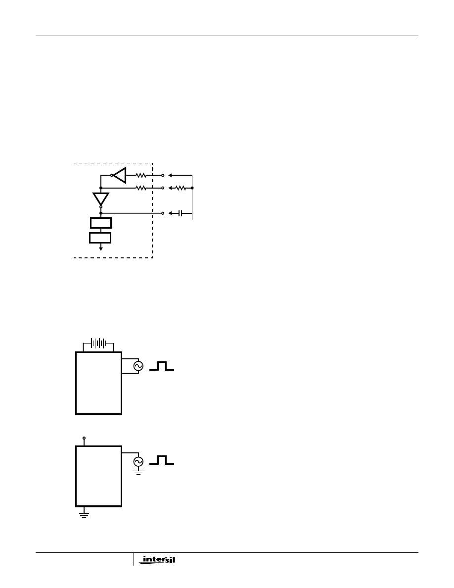
An external clock can also be used. In the ICL7106, the
internal logic is referenced to TEST. External clock
waveforms should therefore swing between TEST and V+
(Figure 7A). In the ICL7107, the internal logic is referenced
to GND so any generator whose output swings from ground
to +5V will work well (Figure 7B).
The Reference
For 200.0mV full scale, the voltage applied between REF Hi
and REF Lo should be set at 100.0mV. For 2.000V full scale,
set the reference voltage at 1.000V. The reference inputs are
floating, and the only restriction on the applied voltage is that
it should lie in the range V- to V+.
The voltage between V+ and COMMON is internally
regulated at about 2.8V. This reference is adequate for many
applications and is used in the evaluation kits. It has a typical
temperature coefficient of 100ppm/
o
C.
The limitations of the on-chip reference should also be
recognized, however. With the ICL7107, the internal heating
which results from the LED drivers can cause some
degradation in performance. Due to its high thermal
resistance, plastic parts are poorer in this respect than
ceramic. The user is cautioned against extrapolating from
the performance of the kit, which is supplied with a ceramic
ICL7107, to a system using the plastic part. The combination
of reference TC, internal chip dissipation, and package
thermal resistance can increase noise near fullscale from
25
µ
V to 80
µ
V
P-P
.
The linearity in going from a high dissipation count such as
1000 (19 segments on) to a low dissipation count such as
1111 (8 segments on) can also suffer by a count or more.
Devices with a positive TC reference may require several
counts to pull out of an overload condition. This is because
overload is a low dissipation mode, with the three least
significant digits blanked. Similarly, units with a negative TC
may cycle between overload and a nonoverload count as the
die alternately heats and cools. These problems are of
course eliminated if an external reference is used.
The ICL7106, with its negligible dissipation, suffers from
none of these problems. In either case, an external
reference can easily be added as shown in Figures 8A or 8B.
FIGURE 6. ICL7106/ICL7107 INTERNAL OSCILLATOR CLOCK
40
39
38
ICL7106/ICL7107
SYSTEM CLOCK
100k
Ω
100pF
÷
2
÷
2
FIGURE 7A. ICL7106
ICL7106
OSC1
TEST
40
37
5V
FIGURE 7B. ICL7107
FIGURE 7. EXTERNAL CLOCK OPTIONS
ICL7107
OSC1
40
5V
5V
0V
Application Note 023
5
Power Supplies
The ICL7106 kit is intended to be operated from a 9V dry
cell. INPUT Lo is shorted to COMMON, causing V+ to sit
2.8V positive with respect to INPUT Lo, and V- 6.2V negative
with respect to INPUT Lo.
The ICL7107 kit should be operated from
±
5V. Noisy
supplies should be bypassed with 6.8
µ
F capacitors to
ground at the point where the supplies enter the board.
INPUT Lo has an effective common mode range with
respect to GND of a couple of volts.
The precise value is determined by the point at which the
integrator output ramps within ~0.3V of one or other of the
supply rails. This is governed by the integrator time constant,
the magnitude and polarity of the input, the common mode
voltage, and the clock frequency: for further details, consult
the data sheet. Where the voltage being measured is
floating with respect to the supplies, INPUT Lo should be
tied to some voltage within the common mode range such as
GROUND or COMMON. If a -5V supply is unavailable,
suitable negative rail can be generated locally using the
circuit shown in Figure 9.
Input Filters
One of the attractive features of the ICL7106 and ICL7107 is
the extremely low input leakage current, typically 1pA at
25
o
C. This minimizes the errors caused by high impedance
passive filters on the input. For example, the simple RC
(1M
Ω
/0.01
µ
F) combination used in the evaluation kits
introduces a negligible 1
µ
V error.
Preliminary Tests
Auto Zero
With power on and the inputs shorted, the display should
read zero. The negative sign should be displayed about 50%
of the time, an indication of the effectiveness of the auto-zero
system used in the ICL7106 and ICL7107. Note that some
competitive circuits flash negative on every alternate
conversion for inputs near zero. While this may look good to
the uninitiated, it is not a true auto zero system!
Over-Range
Inputs greater than full scale will cause suppression of the
three least significant digits; i.e., only 1 or -1 will be displayed.
Polarity
The absence of a polarity signal indicates a positive reading.
A negative reading is indicated by a negative sign.
Further evaluation should be performed with the help of a
precision DC voltage calibrator such as Fluke Model 343A.
Alternatively a high quality 4
1
/
2
digit DVM can be used,
provided its performance has been measured against that of
a reliable standard.
DPM Components: Sources of Supply
It has already been shown that the ICL7106 and ICL7107
require an absolute minimum of additional components. The
only critical ones are the display and the integration capacitor.
The following list of possible suppliers is intended to be of
assistance in putting a converter design into production. It
should not be interpreted as a comprehensive list of
suppliers, nor does it constitute an endorsement by Intersil.
FIGURE 8A.
FIGURE 8B.
FIGURE 8. USING AN EXTERNAL REFERENCE
ICL7106
V+
REF LO
ICL7107
REF HI
V+
V-
6.8V
ZENER
I
Z
ICL7106
V+
REF HI
REF LO
COMMON
V+
ICL8069
1.2V
REFERENCE
ICL7107
FIGURE 9. GENERATING NEGATIVE SUPPLY FROM +5V
ICL7107
V+
OSC 1
V-
OSC 2
OSC 3
GND
V+
V- = 3.3V
0.047
µ
F
10
µ
F
+
-
IN914
IN914
CD4009
Application Note 023

6
All Intersil semiconductor products are manufactured, assembled and tested under ISO9000 quality systems certification.
Intersil semiconductor products are sold by description only. Intersil Corporation reserves the right to make changes in circuit design and/or specifications at any time with-
out notice. Accordingly, the reader is cautioned to verify that data sheets are current before placing orders. Information furnished by Intersil is believed to be accurate and
reliable. However, no responsibility is assumed by Intersil or its subsidiaries for its use; nor for any infringements of patents or other rights of third parties which may result
from its use. No license is granted by implication or otherwise under any patent or patent rights of Intersil or its subsidiaries.
For information regarding Intersil Corporation and its products, see web site http://www.intersil.com
Liquid Crystal Displays
1. LXD Inc., Cleveland, Ohio
2. Hamlin Inc., Lake Mills, Wisconsin
3. IEE Inc., Van Nuys, California
4. Shelley Associates, Irvine, California
5. Crystaloid Electronics, Stow, Ohio
LED Displays (Common Anode)
1. Hewlett Packard Components, Palo Alto, California
2. Itac Inc., Santa Clara, California
3. Litronix Inc., Cupertino, California
4. Monsanto Inc., Palo Alto, California
Polypropylene Capacitors
1. Plessey Capacitors, West Lake Village, California
2. IMB Electronic Products, Santa Fe Springs, California
3. Elcap Components, Santa Ana, CaliforniaTRW
Capacitors, Ogallala, Nebraska
CAUTION: Potential trouble areas when con-
structing the evaluation kits:
1. Certain LCD displays have a protective plastic sheet
covering the plastic top. This sheet may be removed after
installing the display to maximize display viewing.
2. Solder flux or other impurities on PC board may cause
leakage paths between IC pins and board traces reducing
performance and should be removed with rubbing alcohol
or some other suitable cleaning agent. Displays should be
removed when cleaning as damage could result to them.
3. Blue PC board material (PC75) has been treated with a
chemical which may cause surface leakage between the
input traces. It is suggested that the board be scribed
between the input traces and adjacent traces to eliminate
this surface leakage.
In order to ensure that unused segments on the LCD displays
do not turn on, tie them to the backplane pin (pin 21).
References
[1] AN016 Application Note, Intersil Corporation, “Selecting
A/D Converters”, Dave Fullagar, AnswerFAX Doc. No.
9016.
[2] AN017 Application Note, Intersil Corporation, “The
Integrating A/D Converter”, Lee Evans, AnswerFAX
Doc. No. 9017.
[3] AN018 Application Note, Intersil Corporation, “Do’s and
Don’ts of Applying A/D Converters”, Peter Bradshaw
and Skip Osgood, AnswerFAX Doc. No. 9018.
[4] Hewlett Packard (Opto Electronics Div.) Application Note
964, “Contrast Enhancement Techniques”.
[5] AN032 Application Note, Intersil Corporation,
“Understanding the Auto-Zero and Common Mode
Performance of the ICL7106/7107/7109 Family”, Peter
Bradshaw, AnswerFAX Doc. No. 9032.
Application Note 023
7
FIGURE 10. ICL7107 PRINTED CIRCUIT BOARD AND COMPONENT PLACEMENT
Application Note 023
8
FIGURE 11. ICL7107 PRINTED CIRCUIT BOARD AND COMPONENT PLACEMENT
Application Note 023
Wyszukiwarka
Podobne podstrony:
C557B T Rectron elenota pl
BF970 Vishay elenota pl
LM317 Fairchild elenota pl
LM3812 NationalSemiconductor elenota pl
TDA7388 STMicroelectronics elenota pl
TDA7377 UnisonicTechnologies elenota pl
TDA8920 Philips elenota pl
TDA7383 STMicroelectronics elenota pl
TDA7566 STMicroelectronics elenota pl
TDA7266M STMicroelectronics elenota pl
TDA7850 STMicroelectronics elenota pl
INTERsoft IntelliCAD 4 0 PL Pierwsze kroki icad4p
TDA7490LSA STMicroelectronics elenota pl
TDA1908 STMicroelectronics elenota pl (1)
TDA7233 STMicroelectronics elenota pl
TDA7231A STMicroelectronics elenota pl
TDA8580 Philips elenota pl
TDA7360 STMicroelectronics elenota pl
więcej podobnych podstron