
Journal of Biomechanics 38 (2005) 1221–1227
Finite element analysis of covered microstents
Linxia Gu
a
, Swadeshmukul Santra
b
, Robert A. Mericle
b
, Ashok V. Kumar
a,
a
Department of Mechanical & Aerospace Engineering, University of Florida, P.O. Box 116300, Gainesville, FL 32611-6250, USA
b
Department of Neurological Surgery, University of Florida, P.O. Box 100265, Gainesville, FL 32610-0265, USA
Accepted 28 June 2004
Abstract
Currently available neuroendovascular devices are inadequate for effective treatment of many wide-necked or fusiform
intracranial aneurysms and intracranial carotid-cavernous fistulae (CCF). Placing a covered microstent across the intracranial
aneurysm neck and CCF rent could restore normal vessel morphology by preventing blood flow into the aneurysm lumen or CCF
rent. To fabricate covered microstents, our research group has developed highly flexible ultra thin (150 mm) silicone coverings and
elastomerically captured them onto commercially available metal stents without stitching. Preliminary in vivo studies were
conducted by placing these covered microstents in the common carotid artery of rabbits. The feasibility of using covered stents was
demonstrated. However, the cover affected the deployment pressure and the stents failed occasionally during deployment due to
tearing of the cover. Appropriate modeling of covered stents will assist in designing suitable coverings, and help to reduce the failure
rate of covered microstents. The purpose of this study is to use the finite element method to determine the mechanical properties of
the covered microstent and investigate the effects of the covering on the mechanical behavior of the covered microstent. Variations
in the mechanical properties of the covered microstent such as deployment pressure, elastic recoil and longitudinal shortening due to
change in thickness and material properties of the cover have been investigated. This work is also important for custom design of
covered microstents such as adding cutout holes to save adjacent perforating arteries.
r
2004 Elsevier Ltd. All rights reserved.
Keywords: Covered stent; Finite element analysis; Simulation; Silicone; Aneurysm; Arteriovenous fistula
1. Introduction
Intracranial aneurysms and intracranial carotid-ca-
vernous fistulae (CCF) are vascular malformations that
occur in the intracranial compartment. An aneurysm is
an abnormal dilation of a portion of an artery due to a
weakening in the vessel wall either congenitally or by
disease. The two main types of aneurysms that occur are
saccular (berry) and fusiform aneurysms. Saccular
aneurysms have a neck and involve part of the
circumference of the wall whereas fusiform aneurysms
do not have a neck and encompass the entire wall.
Intracranial aneurysms can rupture and hemorrhage
into the brain causing stroke with severe disability or
death. An intracranial CCF is an abnormal direct
connection between the intracranial carotid artery and
the adjacent intracranial cavernous sinus (vein). In this
situation, the high-pressure arterial blood is shunted
directly into the low-pressure venous system without
transversing the lengthy capillary bed. A CCF can cause
venous hypertension, which can lead to a massive
swollen and injected eye (proptosis and chemosis),
glaucoma, blindness, deformity and reduced blood
perfusion to the brain.
Treatment of intracranial aneurysms has traditionally
been accomplished by open craniotomy and aneurysm
clipping. These surgical procedures are invasive and
involve a high risk (
). Many non-invasive endovascular
procedures have been developed to treat lesions such as
ARTICLE IN PRESS
www.elsevier.com/locate/jbiomech
www.JBiomech.com
0021-9290/$ - see front matter r 2004 Elsevier Ltd. All rights reserved.
doi:10.1016/j.jbiomech.2004.06.008
Corresponding author. Tel: +1-352-392-0816; fax: +1-352-392-
1071.
E-mail address: akumar@ufl.edu (A.V. Kumar).

intracranial aneurysms, intracranial CCF, and other
pathological diseases that require redirection or restric-
tion of blood flow in the brain. Endovascular balloons
have been used for occlusion of CCF and parent arteries
for treatment of aneurysms (
). The use of thrombogenic coils for
intracranial aneurysms was first performed in 1989,
although coils were previously used for carotid artery
occlusion (
). Detachable coils are
currently used for some saccular aneurysms with narrow
necks, as the coils are placed within the aneurysm
lumen, while maintaining patency of the parent artery.
Many wide-necked or fusiform aneurysms cannot be
treated with coils because the coils cannot be contained
in the aneurysmal sac (
). Bare stents to
assist in coiling some wide-necked aneurysms was first
described in 1998 (
). However, bare
stents will never be useful for treatment of some complex
wide-necked aneurysms, fusiform aneurysms, or CCF,
because the blood flow is free to pass between the stent
struts and into the aneurysm lumen or fistula rent.
Covered microstents could be used to treat intracra-
nial aneurysms and CCF’s, because the covering would
prevent blood flow into the lesion. A covered stent could
be placed in the parent artery to bridge the abnormality
to occlude blood flow into the aneurysm lumen or CCF
rents. The use of covered stents in the proximal carotid
and vertebral arteries has been reported (
;
;
). For the
intracranial application, the covered stent has to be
miniaturized to fit the smaller, more complexarteries in
the brain. The covered microstent should also be highly
flexible and maneuverable for smooth navigation
because of the increased tortuosity in the intracranial
arteries. This requires that the covering material should
be thin, flexible and should not move relative to the stent
during or after placement. In our research group, a new
kind of seamless covered microstent was developed. In
order to most effectively design appropriate covered
microstents, the mechanical properties of both stent and
covering must be investigated. Clinical application of
covered microstents would be dramatically improved if
we understood and could predict how the mechanical
properties of the covered stent would behave during
deployment. The proper numerical analysis could help
in designing covered stents and provide design-driven
selection of suitable materials.
In this work, an ultra thin silicone covering of
appropriate size was mounted onto a small Palmaz-
Schatz stent before deployment. The effects of the
covering on the primary mechanical performance of the
stent (deployment pressure, elastic recoil and long-
itudinal shortening) was investigated by using finite
element (FE) method. The results were compared to the
mechanical properties of the microstent without cover-
ing. This is necessary to determine optimal deployment
pressures, elastic recoil and longitudinal shortening for
each desired diameter of artery where the covered stent
would be placed in an intracranial artery.
FE analysis has been used to study mechanical
properties of metallic stents, such as deployment
pressure, elastic recoil and flexibility. Several studies
have addressed the effects of stent geometries, the
interaction between the stent and catheter balloon, or
interactions between the stent and arterial wall.
studied the biomechanical interaction
between a balloon-expandable stent and a stenotic
artery.
determined the exact
mechanical characteristics of two different types of
stents: tubular stents and coil stents.
investigated the effects of different geometrical
parameters of a typical diamond-shaped coronary stent
on the mechanical performance, and gave some sugges-
tions for optimizing stent shape and performance.
studied a 2D balloon–artery
interaction. However, no numerical analysis of covered
stents has been published. This work uses FE method to
predict the mechanical properties of covered micros-
tents, which is a critical step towards using these covered
microstents to treat many difficult aneurysms and CCF.
2. Preliminary animal studies
The effect of covered stent placement was initially
evaluated by histological analysis of the normal
common carotid artery (CCA) in the New Zealand
White (NZW) rabbit model. In a typical procedure, a
vascular sheath was placed in the femoral artery of a
NZW rabbit. Using endovascular techniques, a silicone-
covered balloon-expandable stent device was navigated
through the vasculature towards the CCA. The device
was deployed within the vessel and angiography was
performed to confirm patency. Following the device
placement, the animal was monitored for sixweeks.
Angiography of the stented vessel was then performed
to reveal angiographic patency. The animals were then
euthanized and the vessels harvested for histological
examination. Under this preliminary investigation, six
animals were selected. In three cases, the covering ripped
during stent deployment (at approximately 4 atm
pressure) and stenosis occurred in one case. For the
other cases, the placement of these covered microstents
in the rabbit CCA resulted in minimal neointimal
proliferation, which demonstrated the feasibility of
using covered stents. Moreover, the covered stent device
was easily navigated through the vasculature system,
which demonstrates flexibility and maneuverability of
this covered microstent.
In our animal study, we used approximately 150 mm
thick
Silastic
s
T2 silicone
tubing elastomerically
ARTICLE IN PRESS
L. Gu et al. / Journal of Biomechanics 38 (2005) 1221–1227
1222
captured on balloon expandable metal stent. Although
the stent is well optimized for clinical applications, there
will be variations in the mechanical properties such as
deployment pressure, elastic recoil etc. when it is
covered with elastomeric covering. In general, irrespec-
tive of the type of metal stent, the alteration in
mechanical properties of covered stent could be directly
correlated to the mechanical properties of coverings.
For intracranial applications, it is preferred to select
ultra-thin covering in such a way that the covering will
have minimal impact on the flexibility and maneuver-
ability of the balloon-expandable stent system. How-
ever, to select appropriate thickness and material, it is
not practical to perform repeated and expensive
mechanical testing of covered stents with coverings of
various elastomeric materials and thickness. Therefore,
it is necessary to perform FE analysis to assist in
designing stent coverings and selecting materials for the
cover.
3. Analysis and modeling
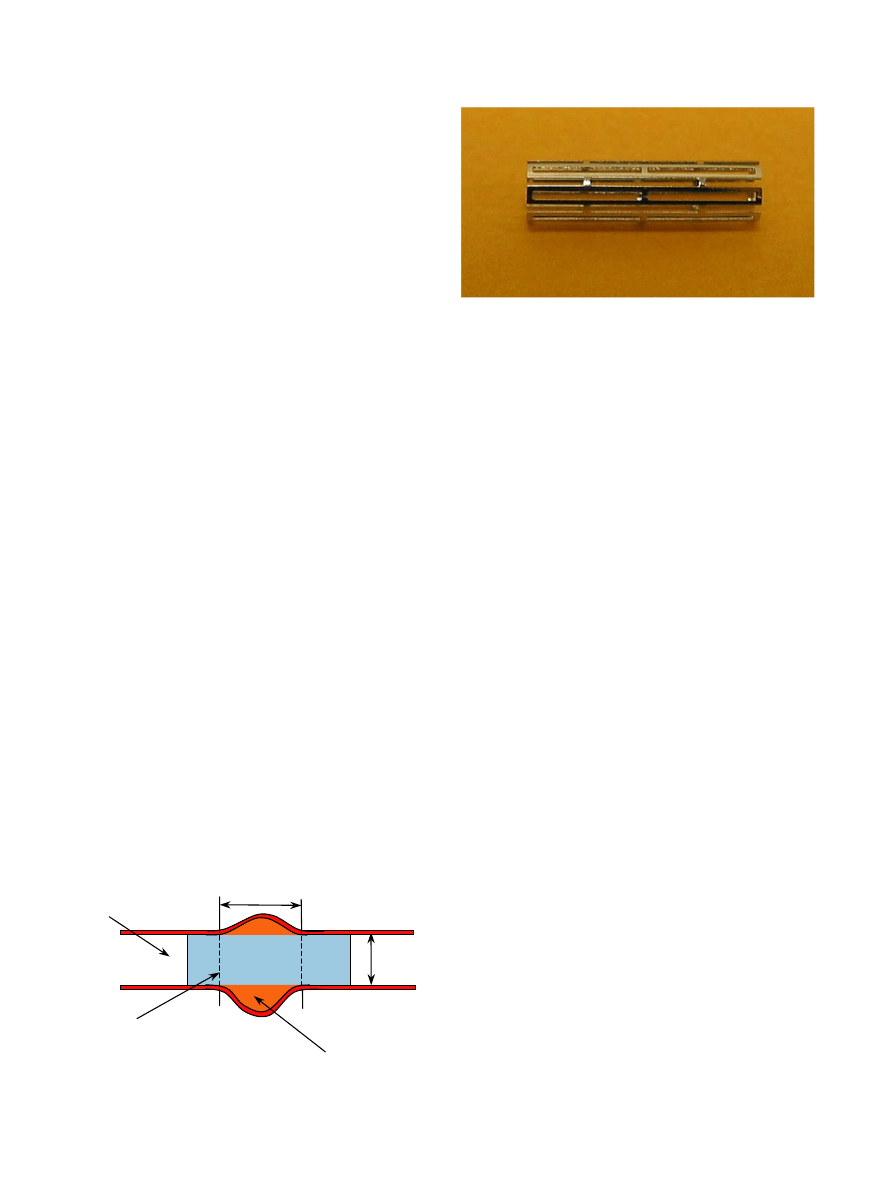
An intracranial artery segment of 2.9 mm lumen
diameter with a 4 mm long fusiform aneurysm is plotted
(
). A covered microstent is placed as shown, across
the aneurysm neck, and inflated by the balloon to 3 mm
diameter to treat this lesion.
3.1. Geometry and material properties
A
balloon-expandable
Palmaz-Schatz
microstent
PS154 (Johnson & Johnson, Warren, NJ, USA) was
modeled in this study. It is a hollow tube with laser cut
slots (
). The modeled stent has an outer diameter
of 1.47 mm, a length of 8.06 mm and a thickness of
0.1 mm. There are 2 slots in the longitudinal direction
and 12 slots circumferentially. The dimension of each
slot is 3.62 mm 0.22 mm. The distal strut length is
0.3 mm, the inner strut length is 0.22 mm, and the metal
strut width is 0.14 mm.
Plastic properties of the material such as yield stress
and hardening depend upon previous work hardening or
history of deformation. In the absence of detailed
material information from the manufacturer, the mate-
rial properties of the stent were adopted from published
literature (
). The microstent was assumed to be made of
316LN stainless steel. The material properties that were
used
for
the
analysis
are:
Young’s
modulus
E ¼ 196 GPa;
Poisson
ratio
n ¼ 0:3;
Yield
stress
s
Y
¼
205 MPa; ultimate stress s
M
¼
515 MPa and the
corresponding ultimate strain
M
¼
60%. The plastic
behavior of the microstent was modeled assuming linear
isotropic hardening between yield stress and ultimate
stress.
Our model considered an ultra thin elastomeric
tubular covering captured on the metal PS154 stent. In
order to address the frequent covering migrations
described in the literature (
we left 0.1 mm of the stent uncovered at each end of the
8.06 mm long microstent. After deployment, the un-
covered stent ends will have a subtle trumpet-like flare.
The uncovered portion of the stent provides a better grip
on the arterial wall to prevent covered microstent
migration.
Silicone covering were made from Silastic
s
T2 base
and Silastic T2 curing agent (Dow Corning
s
, Midland,
MI). The material properties such as elastic modulus and
rupture stress/strain of the silicone covering were
measured using an Instron model 4301 testing instru-
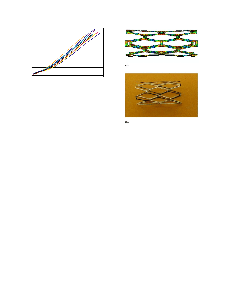
ment. Complete stress versus strain profiles for the ten
samples was thus obtained (
). The average modulus
was 2.47 (
70.14) MPa, and the strain at rupture was 259
(
719.12)%. In our FE modeling, we assumed that the
cover has linear elastic behavior with Young’s modulus
of 2.47 MPa and Poisson’s ratio of 0.3.
3.2. Simulation
FE analysis is widely used as a tool to provide cost-
effective information on product design and test as part
ARTICLE IN PRESS
Deployed
covered stent
4 mm
Aneurysm
Artery
2.9 mm
Fig. 1. Schematic diagram of an intracranial artery segment with a
fusiform aneurysm.
Fig. 2. Photographs of Palmaz-Schatz balloon expandable microstent
in its constricted form.
L. Gu et al. / Journal of Biomechanics 38 (2005) 1221–1227
1223
of the product development process. Considering the
non-linear large plastic deformation of the metallic stent
and the tight contact between the stent and the covering,
we used commercial FE software:
from Hibbitt, Karlsson & Sorensen, Inc., Rhode Island,
USA.
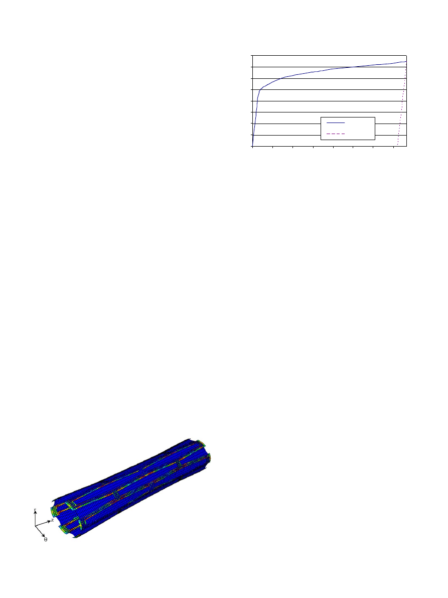
The 3D geometry of the microstent and covering were
developed using commercial software I-DEAS 9 (EDS,
Texas, USA) that has the capability to create complex
solid and surface models, as well as mesh. The whole
stent was meshed with 4-node general shell elements
S4R (
). Due to the circular symmetry of the
geometry it is possible to model just 1/12th of the stent
instead of modeling the entire stent. Even though
identical results were obtained by modeling 1/12th of
the stent, we have shown only results and figures
obtained using models of the complete stent since they
are easier to understand and interpret for non-engineers.
Note that the stent thickness to radius ratio is
approximately 1/7, therefore we have used a thick shell
element that accounts for transverse shear stresses and
strains. If 8-node hexahedral (3D) elements were used, it
would be necessary to use a large number of elements
through the thickness of the stent to accurately capture
the stress variation through the thickness. The complete
geometry of the stent was discretized into 2730 elements
with average length of 0.0796 mm and 3936 nodes. The
covering was discretized into 6272 elements and 6336
nodes with the element length of 0.08 mm.
Careful observation of the in vivo stenting experi-
ments in our lab showed that the balloon is almost
uniformly inflated except at two ends, and the stent is
expanded by the uniformly inflated part of the balloon.
The free ends of the stent are easier to expand than the
central part. Thus, the ends of the stent expand faster at
the beginning of the expansion. The central portion of
the stent continues to be expanded by the balloon until
the stent is almost evenly expanded (
). The
balloon transmits the internal pressure uniformly to the
stent during the expansion. Therefore, a uniform
pressure was applied in our model on the internal
surface of the covered microstent. During loading,
pressure was increased until the final diameter of the
stent reached the value of 3 mm and then the pressure
was unloaded to study recoil. All rotational degrees of
freedom were fixed for the nodes at both ends of the
stent. A non-sliding contact between the covering and
the microstent was prescribed. The initial stress in the
stent and covering were neglected. The different thick-
ness of 0.08, 0.1, 0.12 and 0.15 mm for the covering were
tested under radial pressure load.
4. Results
The primary objective of this work is to compare the
mechanical properties of the covered microstent with
stents that do not have coverings (or bare stent). Stents
were expanded by uniform internal pressure that was
applied in small increments. Large structural deforma-
tion and material non-linearities can pose difficulties due
to non-convergence after certain amount of deforma-
tion. ABAQUS provides automatic mechanisms for
stabilizing this kind of problems through the automatic
addition of volume-proportional damping to the model.
Even so the maximum deformation that can be
simulated using FE analysis is restricted due to non-
convergence if the mesh is severely distorted.
A simple in vitro experiment was performed to study
the expansion of the stent. A bare balloon-expandable
ARTICLE IN PRESS
0.0
1.0
2.0
3.0
4.0
5.0
6.0
0
100
200
300
Strain %
Stress (MPa)
Fig. 3. Nominal stress versus strain curve for Silastic
s
T2 silicone (10
samples).
Fig. 4. Free expanded microstent at 3-mm-diameter with a diamond
shape slot (a) FE element results, (b) in vitro experiment photo.
L. Gu et al. / Journal of Biomechanics 38 (2005) 1221–1227
1224
Palmaz-Schatz stent was expanded by increasing the
pressure in very small steps and the diameter of the stent
was recorded at each pressure.
shows the
expanded stent at the end of the experiment. During the
expansion the slots in the stent expand to a diamond
shape allowing the stent to expand significantly. After
the stent starts deforming plastically the rate of pressure
increase needed to continue expanding the stent was
very low indicating that the stent material does not work
harden significantly.
A FE model of the stent was created and expanded
using uniform pressure. The expanded stent has a
diamond-shaped slot after expanding from the initial
outer diameter of 1.47–3 mm. In he final expanded state,
the diameter at the ends of the stent is slightly larger
than at the center.
shows the expanded stent
obtained by the finite element analysis. The shape of the
expanded stent predicted by the analysis matches the
experimentally observed shape (
). Furthermore,
from FE analysis results, we can see that there are stress
concentrations at the joints, as expected.
The deformation of the covered stent was also
obtained under the uniform internal pressure (
It is clear that the covering expands together with the
stent in the areas where they are in contact, indicating
that the contact model worked as expected. The
uncovered regions at the ends of the stent expanded
more than the covered part. This prevents any move-
ment of the covering with respect to the stent after
deployment. This agrees with the observations during
lab tests described in Section 2.
The diameter of the bare stent (at the mid point)
computed by the FE analysis was plotted as a function
of the applied pressure (
). This plot shows that the
pressure jumped dramatically from 0 to 2.6 atm mostly
during the elastic deformation when the diameter
increased by 0.1 mm for the bare stent. The ratio of
pressure change to diameter change is 26.2 atm/mm.
Then the curve becomes almost flat during the plastic
deformation. The stent experiences large plastic defor-
mation from 1.57 to 3 mm in diameter. The pressure
increased by a relatively small amount (just 1.18 atm)
during this expansion of the stent and the ratio of
pressure increase to diameter increase is only 0.82 atm/
mm. The pressure does not increase much during this
plastic deformation because of the low rate of hard-
ening. This matches with experimental observations that
the pressure does not increase much after the stent starts
deforming plastically. After being unloaded, the stent
recoils back along a line parallel to the elastic portion of
the loading curve.
For the covered microstent, the deployment pressure
versus deformation plot (
) has the same trend as
the plot for the bare stent. The pressure jumps during
the first 0.1 mm deformation. Beyond 0.1 mm deforma-
tion (D ¼ 1:57 mm), the pressure does not increase
significantly. For comparison, the figure includes the
pressure versus deformation plot for the bare stent and a
0.1 mm covering when it is expanded without mounting
on a stent. One of the curves corresponds to a covering
of 0.1-mm-thickness with a lower Young’s Modulus,
E_cover=1.8 MPa. This curve illustrates the effect of
changing the material of the cover to a softer material. It
is clear that a thinner and softer covering is preferred in
the design of the covered microstent because the
deployment pressure decreases.
When a 0.1-mm-thick covering was used, the required
pressure increased by approximately 30% compared to
the bare stent at a deformed diameter of 1.57 mm. Note
that the required pressure to expand covered stent is not
equal to the sum of the pressure for bare stent and the
covering. This is due to the non-sliding contact between
the microstent and the covering. Different covering
thicknesses (0.08, 0.1, 0.12 and 0.15 mm) were tested.
The deployment pressure required versus the thickness
of the covering was plotted using the FE simulation
results (
). The two curves correspond to the
deployment pressure required to expand the covered
stent to a final diameter of 1.54 and 1.57 mm,
respectively. The results in the figure predict that the
ARTICLE IN PRESS
Fig. 5. Deformation of covered microstent.
0
0.5
1
1.5
2
2.5
3
3.5
4
1.47
1.67
1.87
2.07
2.27
2.47
2.67
2.87
Outer Diameter(mm)
Expansion Pressure (atm)
Loading
Unloading
Fig. 6. Deployment pressure as a function of the central outer
diameter of bare stent.
L. Gu et al. / Journal of Biomechanics 38 (2005) 1221–1227
1225
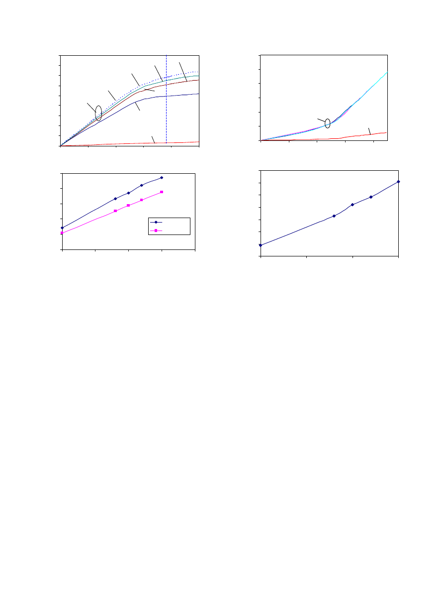
required deployment pressure increases almost linearly
with the thickness of the covering.
Other factors to be considered in the design of
covered microstents include longitudinal shortening
and elastic recoil. Longitudinal shortening is the relative
difference between the initial length of the stent L
0
and
the expanded length L
load
. Elastic recoil is defined as the
difference between the diameter at expanded state D
load
and stent diameter after withdrawing the deployment
pressure D
unload
. The longitudinal shortening remained
almost unchanged with different covering thicknesses
(
). But there is a large difference between the
covered microstents and bare stent. This is because the
covering alone has a much larger longitudinal short-
ening than the bare stent due to the large difference in
elastic modulus. Using Hooke’s law the strain in the
longitudinal
direction
can
be
expressed
as
zz
¼ ð
1=EÞðs
zz
ns
xx
ns
yy
Þ
, where z direction is
assumed to the longitudinal direction and s
xx
; s
yy
; s
zz
are the stress components in the x, y, and z directions,
respectively. Clearly, the strain would be much larger for
a material with smaller Young’s modulus, E even when
the Poisson’s ratio, n, is the same. Therefore, when the
covering is captured onto the stent, it causes a larger
longitudinal shortening for the covered stent. The large
difference in longitudinal shortening between the cover
and stent may cause slippage between the two for some
covering materials if the sliding friction is low. In our
experiments, the covered stents were made by elasto-
merically capturing a thin Silicone cover (a tubular
polymer sheath) onto the metal stent. In the in vivo
experiments, no slippage of the cover was observed
during the expansion of the stent. Therefore, it was
assumed in the FE model that there is no relative slip
between the cover and the stent. The elastic recoil
determines the final diameter of the covered stent after
the balloon withdraws. We can see that the elastic
recoil increases almost linearly with covering thickness
(
5. Discussions
The results above show that the contact between the
stent and the covering influences the mechanical
behavior of the covered stent. The deployment pressure
required to inflate the covered stent was found to be
proportional to the thickness of the covering. Covered
stent was found to have larger longitudinal shortening
than a bare stent but it does not vary significantly with
change in cover thickness. A thinner covering with low
Young’s modulus is desirable because it has lower
ARTICLE IN PRESS
0
0.5
1
1.5
2
2.5
3
3.5
4
4.5
1.47
1.49
1.51
1.53
1.55
1.57
Outer Diameter (mm)
Expansion Pressure (atm)
t=0.15
t=0.08 mm
t=0.1 mm
t=0.12 mm
E_cover=1.8 MPa
Cover
Bare Stent
Covered stent
2
2.4
2.8
3.2
3.6
4
0
0.05
0.1
0.15
0.2
Cover thickness (mm)
Expansion Pressure (atm)
D=1.57 mm
D=1.54 mm
(a)
(b)
Fig. 7. (a) Deployment pressure required to reach 1.57-mm-diameter
in the central area of the stent (P
1.57 mm
) for cases with different
covering thickness t, different Young’s modulus of the covering
E_cover; (b) P
1.57 mm
and P
1.54 mm
versus covering thickness.
0.00%
0.05%
0.10%
0.15%
0.20%
0.25%
0.30%
1.47
1.49
1.51
1.53
1.55
Outer Diameter (mm)
Longitudinal
s
hortening
Covered Stent
Bare stent
3.95%
4.00%
4.05%
4.10%
4.15%
4.20%
4.25%
4.30%
0
0.05
0.1
0.15
Covering Thickness (mm)
Elastic Recoil
(a)
(b)
Fig. 8. (a) Longitudinal shortening at different deformation diameter
for different covering thickness, (b) elastic recoil for different covering
thickness.
L. Gu et al. / Journal of Biomechanics 38 (2005) 1221–1227
1226

deployment pressure and elastic recoil. However, a
thinner covering is more likely to rupture during
expansion. Therefore, it is important to ensure that the
covered microstent can be expanded to the desired
diameter without rupturing the covering. This trade off
needs to be further investigated to improve the design of
the covered microstent.
This work is important for custom design of covered
microstents such as adding cutout holes to save
perforating arteries. Further modeling will be performed
on the design of covering patches, other types of covered
microstent, and different covering materials.
Acknowledgements
This work was supported by the University of Florida
Opportunity Fund 2002, Grant No. 2050260.
References
ABAQUS 6.3-1 documentations, 2002. Hibbitt, Karlsson & Sorensen,
Inc., Rhode Island, USA.
Auricchio, F., Loretob, M.D., Saccoc, E., 2000. Finite-element
analysis of a stenotic artery revascularization through a stent
insertion. Computer Methods in Biomechanics and Biomedical
Engineering 00, 1–15.
Braun, I.S., Hoffman, J.C., Casarella, W.J., Davis, P.C., 1985. Use of
coils for transcatheter carotid occlusion. American Journal of
Neuroradiol 6, 953–956.
Debrun, G., 1979. Cerebral aneurysms: advances in diagnosis and
therapy. In: Pia, H.W., Langmaid, C., Zierski, J. (Eds.), Special
Therapeutic Problems. Springer, New York, pp. 228–236.
Etave, F., Finet, G., Boivin, M., Boyer, J., Rioufol, G., Thollet, G.,
2001. Mechanical properties of coronary stents determined by
using finite element analysis. Journal of Biomechanics 34,
1065–1075.
Ewald, C., Ku¨hne, D., Hassler, W.E., 2000. Bypass-surgery and coil-
embolisation in the treatment of cerebral giant aneurysms. Acta
Neurochirrurgica 142, 731–738.
Fontaine, A.B., Borsa, J.J., Hoffer, E., Bloch, R., So, C., 2001.
Evaluation of silicone as an endovascular stent membrane: in vivo
canine studies. Cardiovascular and Interventional radiology 24 (5),
324–328.
Geremia, G., Bakon, M., Brennecke, L., Haklin, M., Silver, B., 1997.
Experimental arteriovenous fistulas: treatment with silicone-cov-
ered metallic stents. American Journal of Neuroradiology 18 (2),
271–277.
Giannotta, S.L., Litofsky, N.S., 1995. Reoperative management of
intracranial aneurysms. Journal of Neurosurg 83, 387–393.
Johnston, S.C., Zhao, S., Dudley, R.A., Berman, M.F., Gress, D.R.,
2001. Treatment of unruptured cerebral aneurysms in California.
Stroke 32, 597–605.
Laitinen, L., Servo, A., 1978. Embolization of cerebral vessels with
inflatable and detachable balloons—technical note. Journal of
Neurosurgery 48, 307–308.
Marty, B., Leu, A.J., Mucciolo, A., von Segesser, L.K., 2002. Biologic
fixation of polyester- versus polyurethane-covered stents in a
porcine model. Journal of Vascular and Interventional Radiology
13 (6), 601–607.
Mericle, R.A., Lanzino, G., Wakhloo, A.K., Guterman, L.R.,
Hopkins, L.N., 1998. Stenting and secondary coiling of intracranial
internal carotid artery aneurysm. Neurosurgery 43, 1229–1234.
Migliavacca, F., Petrini, L., Colombo, M., Auricchio, F., Pietrabissa,
R., 2002. Mechanical behavior of coronary stents investigated
through the finite element method. Journal of Biomechanics 35,
803–811.
Najibi, S., Bush, R.L., Terramani, T.T., Chaikof, E.L., Gunnoud,
A.B., Lumsden, A.B., Weiss, V.J., 2002. Covered stent exclusion of
dialysis access pseudoaneurysms. Journal of Surgical Research 106
(1), 15–19.
Rogers, C., Tseng, D.Y., Squire, J.C., Edelman, E.R., 1997. Balloon-
artery interactions during stent placement: a finite element analysis
approach to pressure, compliance, and stent circulation. In
Proceedings of the 23rd Annual Meeting of the Society for
Biomaterials. New Orleans, La.
Schellhammer, F., Wahkloo, A.K., Nagursky, H., Schumacher, M.,
1999. Vein graft-coated stents for endovascular occlusion of canine
experimental arteriovenous fistulae. Investigative Radiology 34 (1),
22–27.
ARTICLE IN PRESS
L. Gu et al. / Journal of Biomechanics 38 (2005) 1221–1227
1227
Document Outline
Wyszukiwarka
Podobne podstrony:
Probabilistic slope stability analysis by finite elements
Butterworth Finite element analysis of Structural Steelwork Beam to Column Bolted Connections (2)
FINITE ELEMENT METHOD II 09 intro
9 Finite Element Method using ProENGINEER and ANSYS
Finite Element Analysis with ANSYS
Probabilistic slope stability analysis by finite elements
Butterworth Finite element analysis of Structural Steelwork Beam to Column Bolted Connections (2)
FINITE ELEMENT METHOD II 09 intro
Finite Element Analysis with ANSYS
Intro to the Finite Element Method [lecture notes] Y Liu (1998) WW
Wyk 02 Pneumatyczne elementy
Elementy prawa prawo administracyjne
7 Mikro i makro elementy naszej diety
więcej podobnych podstron