
SERVICE MANUAL
DA315BN6R
D21B8BN6R
I. Safety Instructions .................................................................................................................. 2
II. Specifications ..........................................................................................................................4
III. Level List of Equipments & Instruments Required for Production .................................... 6
IV.Applying Adhesive on Main PCB .......................................................................................... 6
V. Wiring Diagram .......................................................................................................................7
VI.Block Diagram ........................................................................................................................8
VII.Disassembly ..........................................................................................................................9
VIII.Input Signals & Equipments List for Alignment ................................................................. 9
IX. E
2
PROM (IC602) Setting ................................................................................................... 10
X. Electrical Adjustment .......................................................................................................... 12
XI.Transistor and IC Identification .......................................................................................... 16
XII.Schematic Diagram ............................................................................................................ 17
XIII.Component Diagrams ....................................................................................................... 19
XIV.Exploded View Diagram and Parts List ........................................................................... 24
Models:
This manual is the latest at the time of printing, and does not include the modification which
may be made after the printing, by the constant improvement of product.
2
PRECAUTIONS DURING SERVICING
1.
In addition to safety, other parts and assemblies are
specified for conformance with such regulations as
those applying to spurious radiation. These must
also be replaced only with specified replacements.
Examples: RF converters, tuner units, antenna
selection switches, RF cables, noise-blocking
capacitors, noise-blocking filters, etc.
2.
Use specified internal Wiring. Note especially:
1) Wires covered with PVC tubing
2) Double insulated wires
3) High voltage leads
3.
Use specified insulating materials for hazardous
live parts. Note especially:
1) Insulating Tape
2) PVC tubing
3) Spacers (insulating barriers)
4) Insulating sheets for transistors
5) Plastic screws for fixing micro switches
4.
When replacing AC primary side components
(transformers, power cords, noise blocking
capacitors, etc.), wrap ends of wires securely about
the terminals before soldering.
5.
Make sure that wires do not contact heat generating
parts (heat sinks, oxide metal film resistors, fusible
resistors, etc.)
6.
Check if replaced wires do not contact sharply edged
or pointed parts.
7.
Make sure that foreign objects (screws, solder
droplets, etc.) do not remain inside the set.
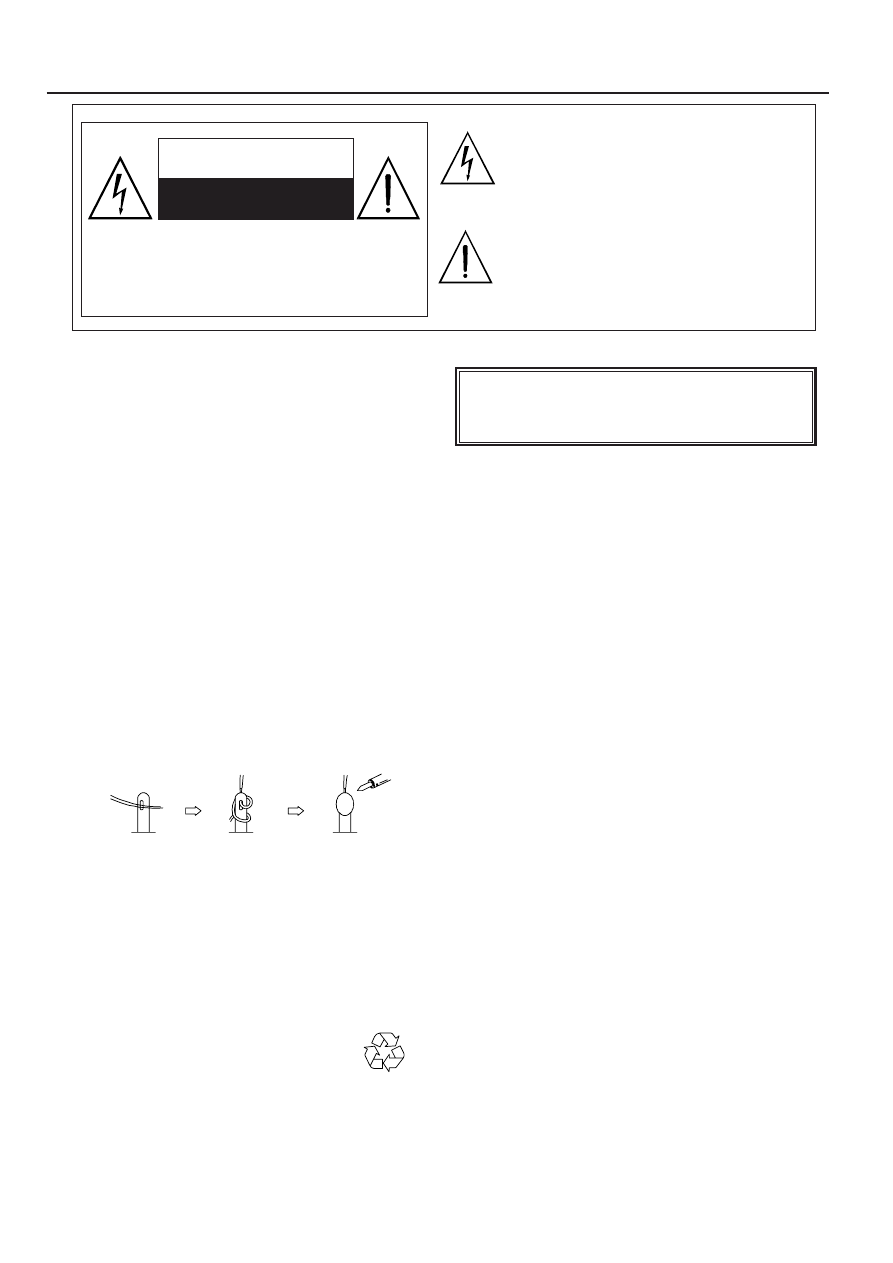
MAKE YOUR CONTRIBUTION TO PROTECT
THE ENVIRONMENT
Used batteries with the ISO symbol
for recycling as well as small
accumulators (rechargeable batteries), mini-batteries
(cells) and starter batteries should not be thrown
into the garbage can.
Please leave them at an appropriate depot.
I. Safety Instructions
WARNING:
Before servicing this TV receiver, read the X-RAY
RADIATION PRECAUTION, SAFETY INSTRUCTION
and PRODUCT SAFETY NOTICE.
X-RAY RADIATION PRECAUTION
1.
Excessively high can produce potentially hazardous
X-RAY RADIATION. To avoid such hazards, the high
voltage must not exceed the specified limit. The
normal value of the high voltage of this TV receiver
is 27 KV at zero bean current (minimum brightness).
The high voltage must not exceed 30 KV under any
circumstances. Each time when a receiver requires
servicing, the high voltage should be checked. The
reading of the high voltage is recommended to be
recorded as a part of the service record, It is
important to use an accurate and reliable high
voltage meter.
2.
The only source of X-RAY RADIATION in this TV
receiver is the picture tube. For continued X-RAY
RADIATION protection, the replacement tube must
be exactly the same type as specified in the parts
list.
3.
Some parts in this TV receiver have special safety
related characteristics for X-RADIATION protection.
For continued safety, the parts replacement should
be under taken only after referring the PRODUCT
SAFETY NOTICE.
SAFETY INSTRUCTION
The service should not be attempted by anyone
unfamiliar with the necessary instructions on this TV
receiver. The following are the necessary instructions
to be observed before servicing.
1.
An isolation transformer should be connected in the
power line between the receiver and the AC line
when a service is performed on the primary of the
converter transformer of the set.
2.
Comply with all caution and safety related provided
on the back of the cabinet, inside the cabinet, on the
chassis or picture tube.
The lightning flash with arrowhead symbol,
within an equilateral triangle, is intended to alert
the user to the presence of uninsulated “dangerous
voltage” within the product’s enclosure that may
be of sufficient magnitude to constitute a risk of
electric shock to persons.
The exclamation point within an equilateral
triangle is intended to alert the user to the
presence of important operating and maintenance
(servicing) instructions in the literature accompa-
nying the appliance.
CAUTION: TO REDUCE THE RISK OF ELEC-
TRIC SHOCK, DO NOT REMOVE COVER (OR
BACK). NO USER-SERVICEABLE PARTS
INSIDE. REFER SERVICING TO QUALIFIED
SERVICE PERSONNEL ONLY.
CAUTION
RISK OF ELECTRIC SHOCK
DO NOT OPEN
3
PRODUCT SAFETY NOTICE
Many electrical and mechanical parts in this TV
receiver have special safety-related characteristics.
These characteristics are offer passed unnoticed by
visual spection and the protection afforded by them
cannot necessarily be obtained by using replacement
components rates for a higher voltage, wattage, etc.
The replacement parts which have these special
safety characteristics are identified by
marks on
the schematic diagram and on the parts list.
Before replacing any of these components, read the
parts list in this manual carefully. The use of
substitute replacement parts which do not have the
same safety characteristics as specified in the parts
list may create shock, fire, X-RAY RADIATION or
other hazards.
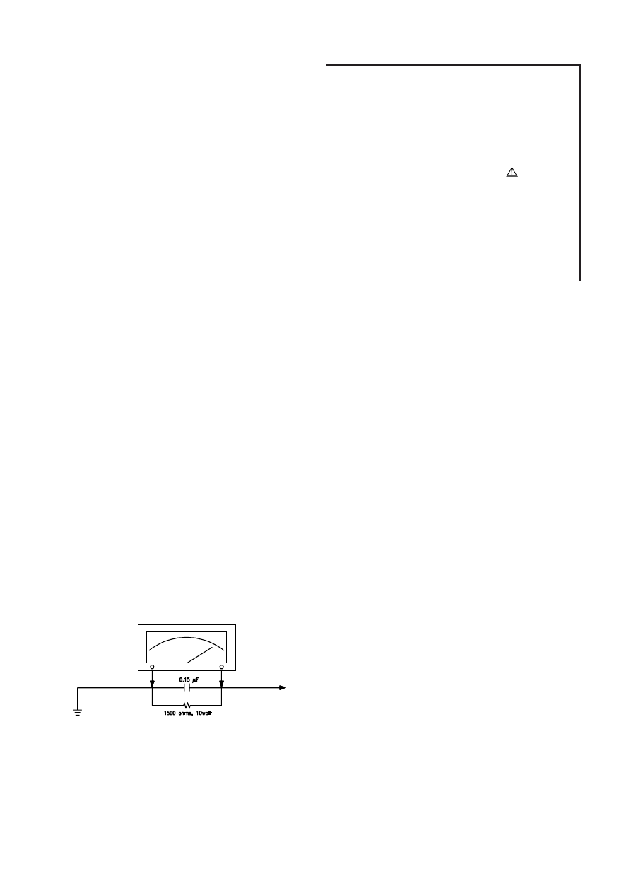
Good earth ground
such as the water
pipe, conductor, etc.
Place this probe
on each exposed
metallic part
AC VOLTMETER
AC Leakage Current Check
3.
To avoid a shock hazard, always discharge the
picture tube's anode to the chassis ground before
removing the anode cap.
4.
Completely discharge the high potential voltage of
the picture tube before handling. The picture tube is
a vacuum and if broken, the glass will explode.
5.
When replacing a MAIN PCB in the cabinet, always
be certain that all protective are installed properly
such as control knobs, adjustment covers or shields,
barriers, isolation resistor networks etc.
6.
When servicing is required, observe the original lead
dressing. Extra precaution should be given to assure
correct lead dressing in the high voltage area.
7.
Keep wires away from high voltage or high tempera
ture components.
8.
Before returning the set to the customer, always
perform an AC leakage current check on the exposed
metallic parts of the cabinet, such as antennas,
terminals, screwheads, metal overlay, control shafts,
etc., to be sure the set is safe to operate without
danger of electrical shock. Plug the AC line cord
directly to the AC outlet (do not use a line isolation
transformer during this check). Use an AC voltmeter
having 5K ohms volt sensitivity or more in the
following manner.
Connect a 1.5K ohm 10 watt resistor paralleled by a
0.15µF AC type capacitor, between a good earth
ground (water pipe, conductor etc.,) and the exposed
metallic parts, one at a time.
Measure the AC voltage across the combination of
the 1.5K ohm resistor and 0.15 uF capacitor. Reverse
the AC plug at the AC outlet and repeat the AC
voltage measurements for each exposed metallic
part.
The measured voltage must not exceed 0.3V RMS.
This corresponds to 0.5mA AC. Any value exceeding
this limit constitutes a potential shock hazard and
must be corrected immediately.
The resistance measurement should be done
between accessible exposed metal parts and power
cord plug prongs with the power switch "ON". The
resistance should be more than 6M ohms.

4
II. Specifications
1. Power supply
TV
:
AC 220~240 V, 50Hz
Remote control battery:
3V (UM-3X2)
2. TV system
RF input
:
PAL BG/DK, SECAM BG/DK
Video input
:
PAL/SECAM/NTSC 3.58/NTSC 4.43
3. Receiving channels
VHF-L
:
E2-S9
VHF-H
:
S10-S40
UHF
:
S41-E69
4. Intermediate frequencies Picture
:
38.9MHz
5. Scanning
Horizontal (Hz) :
15625/15750
Vertical (Hz)
:
50/60
6. Color picture tube:
14” 90 degree North(1) hemisphere Bv=-0.35G±0.2G
21” 90 degree North(3) hemisphere Bv=+0.35G±0.2G
7. Operating temperature
Fulfil all specifications: 15°C ~ 35°C
Accept picture/tone reproduction: 5°C ~ 45°C
8. Operating relative humidity
Fulfil all specifications: 45% ~ 75%
Accept picture/tone reproduction: 15% ~ 90%
9. Electrical & Optical Specification:
No.
Items
Instruction
Typical
Limit
Unit
1
Video sensitivity
For 30dB S/N
VL
≤
45
≤
48
VH
≤
45
≤
48
dBuV
U
≤
48
≤
51
2
FM sound sensitivity
For 30dB S/N
30
≤
35
dBuV
3
Synchronizing sensitivity
For RF transmission
25
≤
30
dBuV
4
Color sensitivity
For RF transmission
32
≤
40
dBuV
5
Teletext sensitivity
TV screen refreshes 40 times
number of mistakes
≤
8
N/A
N/A
dBu
6
Minimum NICAM threshold
Without crackline noise
N/A
N/A
dBu
7
AGC static characteristic
Accept. Picture/tone repr.
103
≥
100
dBu
8
Selectivity
Adjacent sound carrier
40
≥
35
Below adjacent sound carrier
35
≥
30
dB
Adjacent picture carrier
50
≥
40
Up adjacent picture carrier
45
≥
30
9
IF rejection
55
≥
50
dB
10
Image rejection
VHF
55
≥
50
dB
UHF
50
≥
45
11
AFT pull-in range
M/N
N/A
N/A
MHz
DK/BG
±1.5
≥|
±1.0|
12
Chroma sync pull-in range
±500
≥
|±200|
Hz
13
Color killer function
-25
≤
-16
dB
14
DC restoration
3
≤
10
%
15
Resolution
Horizontal
PAL/SECAM
320
≥
300
NTSC
270
≥
250
Vertical
PAL/SECAM
410
≥
400
lines
NTSC
320
≥
300
16
Overscan
Cross hatch signal
93
90~96
%
17
Linearity
Horizontal
7
≤
10
%
Vertical
6
≤
8
%
18
Pattern distortion
1.5
≤
3
%
19
Picture position
In all direction
±3
≤
|±6|
mm
20
Raster rotation
In all direction
4
≤
6
mm
21
Convergence error
0.4
≤
0.6
%
22
White balance (8700°K)
X
0.288
0.288±0.015
Y
0.298
0.298±0.015
/
23
Maximum full white
At picture tube center
110
100
cd/m
2
24
H sync pull-in range
±500
≥
|±200|
Hz
25
V sync pull-in range
7
≥
6
Hz
26
Anode voltage
22
≤
25
KV
(For A315)
24
≤
27.5
KV
(For 21B8)
27
Audio frequence response
±3dB ref. to 1KHz
0.2~8
0.2~8
KHz
28
Audio output power
1KHz 10% THD
3.7x1
≥
3x1
W
(For A315)
50KHz DEV. (BG/I/DK)
25KHz DEV. (M/N)
1.9x2
≥
1.5x2
W
(For 21B8)
5
No.
Items
Instruction
Typical
Limit
Unit
29
THD
Po=0.5W 1KHz
1
≤
3
%
30
Signal to buzz ratio
42
≥
40
dB
31
Minimum volume hum
6
≤
10
mVrms
32
Maximum woofer output power
N/A
N/A
W
33
Woofer audio freqency response
±3dB ref. to 80Hz AV mode
N/A
N/A
Hz
34
Bass control range
100Hz ref. to 1KHz AV mode
N/A
N/A
dB
35
Treble control range
10KHz ref. to 1KHz AV mode
N/A
N/A
dB
36
Balance
Center
N/A
N/A
Max.
N/A
N/A
dB
Min.
N/A
N/A
37
Volume control curve
N/A
/
38
Video input level
1.0
1±0.2
Vpp
39
Audio input level
0.5
0.5±0.3
Vrms
40
Video output level
1.0
1±0.2
Vpp
41
Audio output level
0.5
0.5±0.2
Vrms
42
Power consumpution
Operating
65
≤
80
W
(For A315)
75
≤
95
W
(For 21B8)
(AT 220V AC)
Stand by
10
≤
15
W
43
IR receiving distance
±30°
6
≥
4
m
44
X-ray radiation
<0.1
≤
0.5
mR/h
45
Dielectric strength
AC 3KVrms 1min.
3
≤
5
mArms
Test Condition
1
Picture Modulation
87.5%
2
Sound Modulation
27KHz Dev. For DK/I/BG
15KHz Dev. For M/N
3
Picture to Sound Ration
10dB
4
Sound Artificial Load Resistor
8 ohm
5
Video signal
White and black
(three white & two black)
6
Audio signal
1KHz sine wave 0.5Wrms
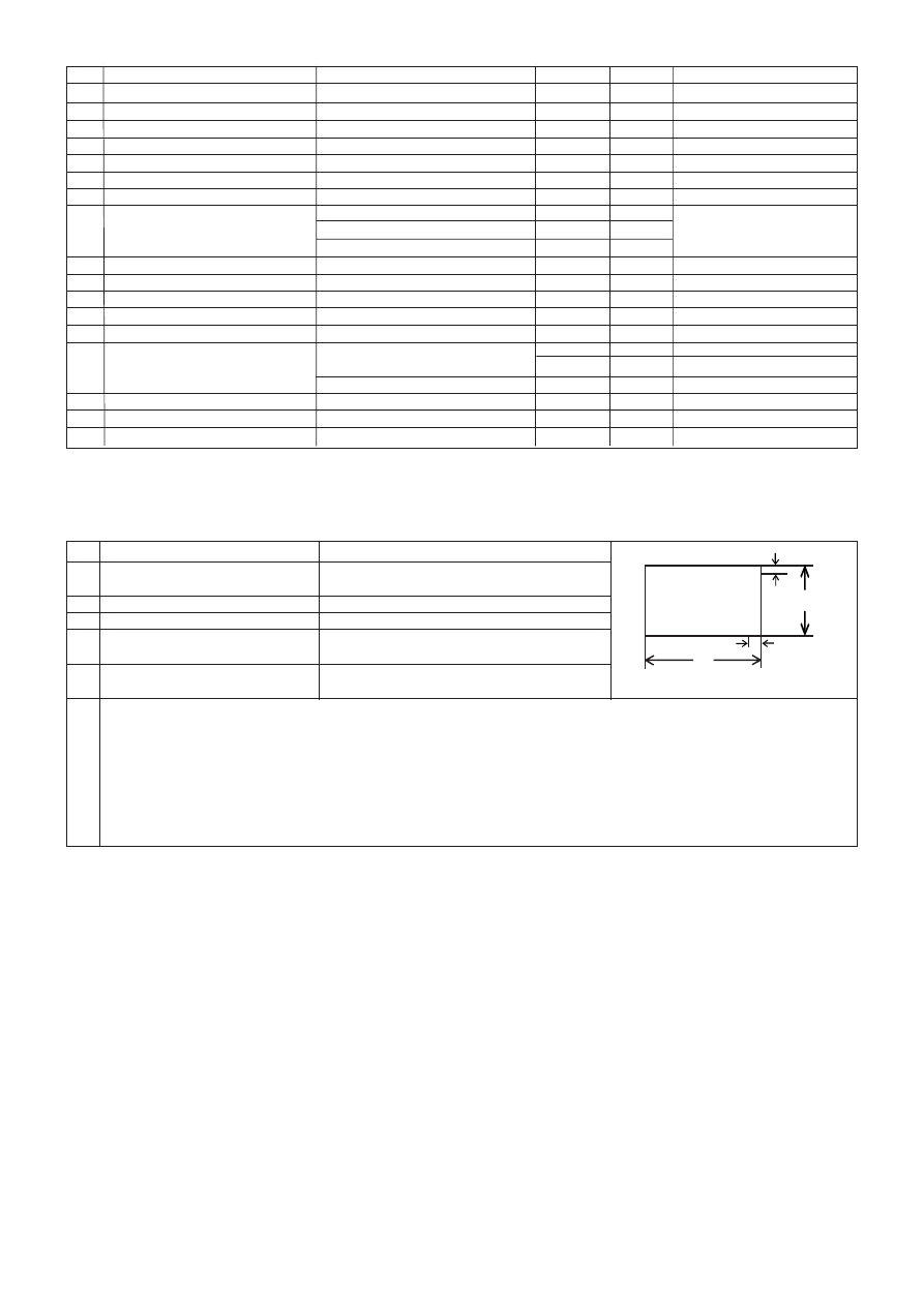
Convergence error test point on
7
Conditions of the TV setting:screen
A. Switch TV on and let it warm up for more than 30 minutes.
B. Connect RMS volt meter to speaker terminals and adjust theTV volume to get 500mW RMS power at each terminal.
C. Place the MINOLTA CA-100 test probe to white part of the screen,adjust the contrast until a reading of 80cd/m
2
is obtained.
D. Place the MINOLTA CA-100 test probe to black part of the screen,adjust the brightness until a reading of 2cd/m
2
is obtained.
E. Repeat step C & D until the exact luminance values is obtained or the nearest possible values you can get.then record the
luminance values & R.G.B gun voltage values at the same time. and take the largest values for measurement referenct.
F. Input standard color bar(100/0/75/0),then adjust the colour.until the waveforms at the blue gun of same level is obtained.
W
H
1/9H
1/9W
+P8
P5+
+P7
P6+
+P1
+P3
+P4
P2+
+P0
6
No. Designation
Requirement
Reference Model
Remark
1
Pattern Generator
System of output signal:
PHILIPS
RF out: PAL BG/SUB/DK/I,
PM5518-TN
SECAM B/G/D/K, NTSC M
PM5418-TN
Video out: NTSC 4.43/3.58 PAL 60Hz
2
Digital voltmeter
Input Resistance 10M
FLUKE 45
3
Withstanding
Withstanding Voltage:
KIKUSUI TOS 8650
Irresistible Voltage Measure
Voltage Tester
AC 1.5KV, 5KV/0-5KV ± 3%
Cut-off current: AC 0-2mA,
20mA / continuously Adjustable
4
Insulation Tester
Test voltage:1000V. 500V
KIKUSUI TOS 7100L
5
Sine wave Signal
Frequency Range: 0.1~140MHz
LEADER 3216
For generating IF Signal
Generator
( Precision:10KHz )
Level Range: -20~126dB
6
Oscilloscope
Frequency response: 20MHz or above
7
CRT Color
MINOLTA CA-100
For White Balance Adjustment
Analyzer
8
DC Regulated
Max output Voltage 14V
Supply DC power
Power Supply
9
Color Monitor
AV receiving system: Should include
Same model (of TV set)
For operation check
all the AV output system of the
as the products
For resolution check
products at least.
For Skew Check
10 Audio Signal
Frequency of output signal:
KENWOOD AG-203A
For generating audio signal
Generator
20Hz-20kHz
III. Level List of Equipments & Instruments Required for Production
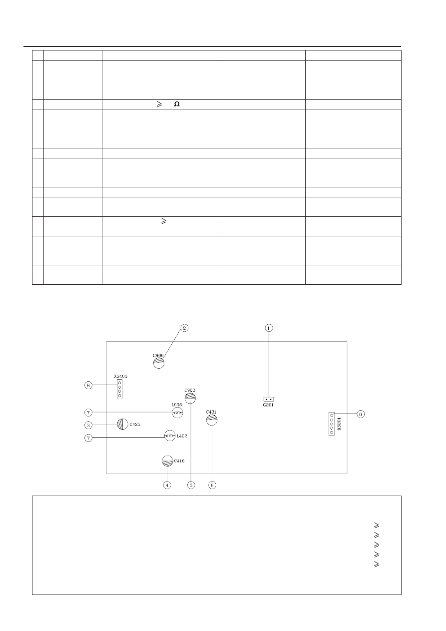
IV. Applying Adhesive on Main PCB
No.
Description
QTY
Action
Remark
1.
Diabond 1603HFR lvoruy Adhesive
1
Apply
Beside the Crystal oscillator
2.
Diabond 1603HFR lvoruy Adhesive
1
Apply
Beside the Capacitors which diameter
15MM
3.
Diabond 1603HFR lvoruy Adhesive
1
Apply
Beside the Capacitors which diameter
15MM
4.
Diabond 1603HFR lvoruy Adhesive
1
Apply
Beside the Capacitors which diameter
15MM
5.
Diabond 1603HFR lvoruy Adhesive
1
Apply
Beside the Capacitors which diameter
15MM
6.
Diabond 1603HFR lvoruy Adhesive
1
Apply
Beside the Capacitors which diameter
15MM
7.
Diabond 1603HFR lvoruy Adhesive
2
Apply
Beside the Coil
8.
Diabond 1603HFR lvoruy Adhesive
2
Apply
At the ends of each jumper wire
7
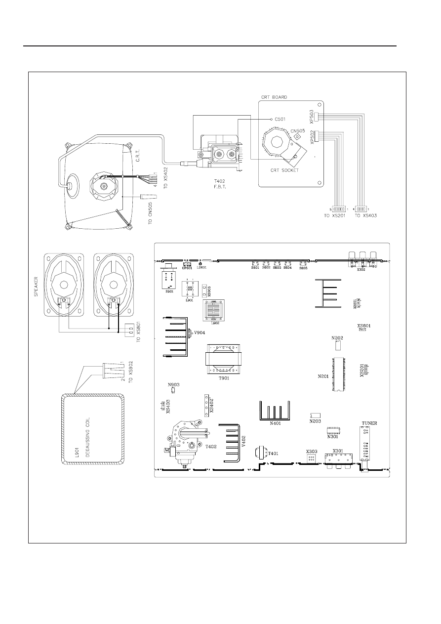
V. Wiring Diagram
8
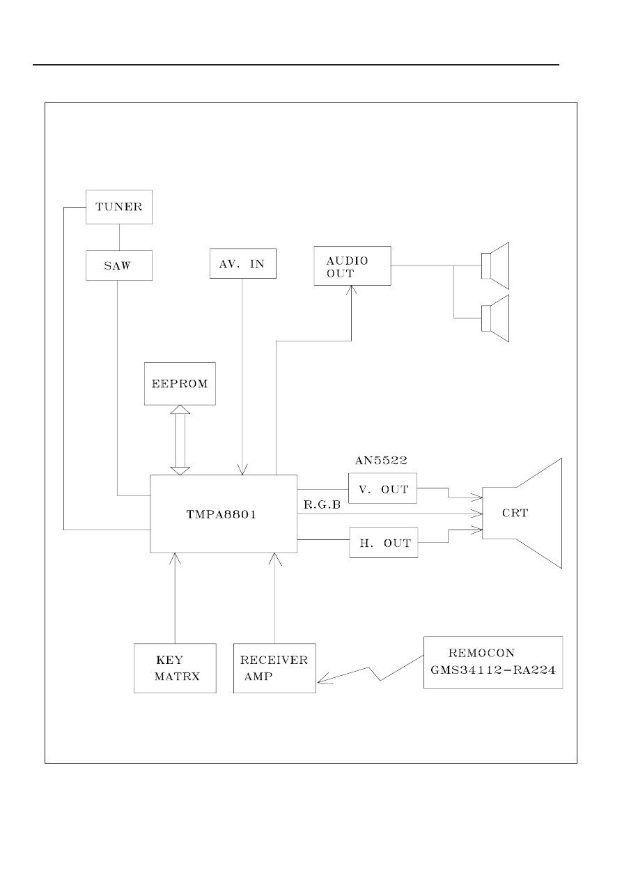
VI. Block Diagram
9
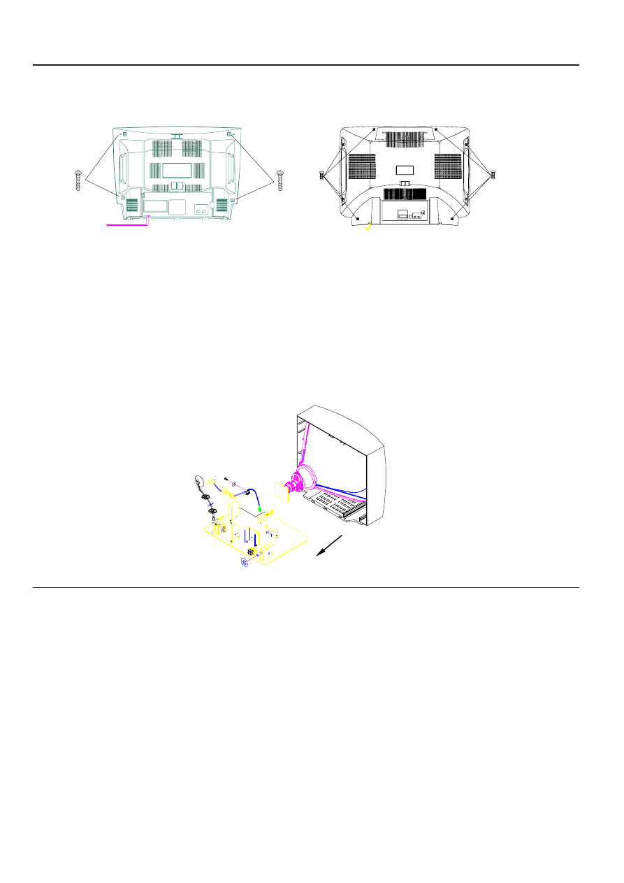
VII. Disassembly
In case of trouble, etc., necessitating disassemble, please disassemble in the order shown in the illustrations. Reas-
semble in the reverse order.
1.
Removal of the Back Cover
2.
Removal of the MAIN PCB
a. Remove the screws.
b. Slide out the TV chassis slightly; pull up the connector of AC cord from PCB; pull up the CRT PCB from
CRT.
c.
Remove the anode cap from the picture tube. To avaid a shock hazard, be sure to discharge the picture
tube’s anode to the chassis ground before removal.
d. Take out the TV chassis.
VIII. Input Signals & Equipments List for Alignment
A. Equipments for adjustment
a. Pattern generator(PHILIPS PM 5518)
b.
Digital voltmeter
c.
High voltage meter
d.
Demagnetiser
e. Personal computer (486)
f.
CRT colour analyzer (MINOLTA CA-100)
g. High voltage probe
B. Input signals
a. Color bar
b.
Cross hatch
c.
Grey scale bar
d.
Monoscope pattern
e. Circle cross pattern
(for 21B8)
(for A315)
10
IX. E
2
PROM setting
A.
Details of tuning voltage, band, AFT, last position, volume, analog output, power status, colour system,
sound system and other setting data are stored in E
2
PROM.
B.
Data Setting
Following data should be preset into the E
2
PROM IC before they are inserted to PCB.
Remark: * means this item can be adjusted according to the TV set’s status.
PARAMETER
REMARK
VALUE (HEX)
BN6R
* RCUT
R cut off
3F
* GCUT
G cut off
3F
* BCUT
B cut off
3F
* GDRV
G drive
3F
* BDRV
B drive
3F
* CNTX
contrast Max.
7F
* BRTC
bright center
3F
* COLC
colour center NTSC
2E
* TNTC
TINT center
3F
* COLP
colour center PAL(Difference form COLC)
0F
* COLS
colour center SECAM
3F
* SCOL
sub color
04
* SCNT
contrast
08
* CNTC
contrast center
5F
* CNTN
contrast minimum
12
* BRTX
bright Max. (difference from center)
2F
* BRTN
bright Min. (difference from center)
2F
* COLX
colour Max. (difference from center)
2F
* COLN
colour Min.
00
* TNTX
TINT Max. (difference from center)
7F
* TNTN
TINT Min. (difference from center)
7F
ST3
sharp center 3.58NTSC TV
20
SV3
sharp center 3.58NTSC VIDEO
20
ST4
sharp center other TV
20
SV4
sharp center other VIDEO
20
SVD
sharp center DVD
19
ASSH
asymmetry-sharpness
04
* SHPX
sharpness Max. (difference from center)
3F
* SHPN
sharpness Min. (difference from center)
1F
TXCX
TEXT RGB contrast Max.
1F
RGCN
TEXT RGB contrast Min.
00
ABL
ABL data in detail
2A
DCBS
a part of Video data in detail
33
CLTO
the data when TV mode &
24
SOUND SYS != M
44
CLTO
the data when TV mode &
44
SOUND SYS != M
CLVO
the data when YUV mode &
45
SOUND SYS != M
CLVD
the data when TV mode &
40
SOUND SYS = M
DEF
a part of DEF COMP data in detail
01
AKB
AKB system
00
SECD
SECAM mode
08
* HP0S
horizontal phase
0F
* VP50
vertical phase 50Hz
03
* HIT
hight 50Hz
1D
* HPS
horizontal position 60Hz
02
(difference from HPOS)
* VP60
vertical position 60Hz
01
* HITS
hight 60Hz (difference from HIT)
01
* VLIN
V linearity 50Hz
04
* VSC
VS correction 50Hz
00
* VLIS
V linearity 60Hz (difference from VLIN)
00
* VSS
VS correction 60Hz (difference from VSC)
00
* SBY
SECAM B-Y black adjust
08
* SRY
SECAM R-Y black adjust
08
* BRTS
sub bright
00
* RAGC
RF AGC adjustment
1A
11
Remark:
The items with “ * ” mean that they can be adjusted.
PARAMETER
REMARK
VALUE (HEX)
BN6R
HAFC
AFC gain
00
V25
volume 25
30
V50
volume 50
41
V100
volume 100
65
MUTT
Y-mute for soft start
00
STAT
contrast up for soft start
00
FLG0
flags for IF
84
FLG1
flags
04
REFP
REF pulse position
00
RSNS
R sens
00
GSNS
G sens
00
BSNS
B sens
00
MOD
mode
30
STBY
VCD/IF stanby
00
SVM
SVM
00
VBLK
V BLK start/stop
00
VCEN
V centering
16
HSIZ
H SIZE
00
PRBR
parabola
00
TRUM
trapzium
00
ECCT
EW-corner correction (top)
00
ECCB
EW-corner correction (bottom)
00
EHT
V EHT / H EHT
24
UCOM
micion control
00
PYNX
normal H.SYNC max.
28
PYNN
normal H.SYNC min
18
PYXS
search H.SYNC max.
22
PYNS
search H.SYNC min
1E
R CUTS
YCbCr R cut off (difference from RCUT)
00
G CUTS
YCbCr G cut off (difference from GCUT)
00
B CUTS
YCbCr B cut off (difference from BCUT)
00
G DRVS
YCbCr G drive (difference from GDRV)
00
B DRVS
YCbCr B drive (difference from BDRV)
00
NOIS
HAFC control
04
A OPT
AKB option
06
AV OPT
AV option
02
OPT2
LANG option
A0
WAIT TIME
Time used for open screen
00
CUR CEN
Center position of the curtain
00
CUR STEP
Open or close curtain step
01
AUSTP
AUDIO step
N/A
MODE 0
mode setting 1
2D
MODE 1
mode setting 2
85
* OSDF
OSD PLL data
58
* OSD
OSD horizontal position
14
OPT
optional setting
67

12
X. Electrical Adjustment
i. +B Voltage Alignment
a. Preparation Procedure.
1.
Turn the TV set on and set it to TV mode with colour bar signal.
2.
Press the key “I.P.C.” on the remote handset to select “MEMORY 1” mode.
3.
Connect digital voltmeter between a terminal of C923 (+B) and GND.
b. Adjustment step
Adjust RP901 to make the read-out on the voltmeter to be 105±0.5VDC(Except 2109/W3BN65 106±0.5VDC).
ii. Adjust for V-centre
a. Adjustment for 50Hz V-centre
1.
Receive
(Circle +Cross) pattern signal (PAL, DK system).
2.
Press the “FACTORY” key on the service remote handset.
3.
Press “P+/P-” key to select VP50 adjustment.
4.
Press “V+/V-” key to get a good V-Centre picture, as shown in Fig.2.
b. Adjustment for 60Hz V-centre
1.
Receive
(Circle +Cross) pattern signal (NTSC 3.58 system) (AV INPUT).
2.
Press the “FACTORY” key on the service remote handset.
3.
Press “P+/P-” key to select VP60 adjustment.
4.
Press “V+/V-” key to get a suitable V-Centre for NTSC system, as shown in Fig.2.
(Fig.2)
(Fig.1)
RP901
C923

13
iii. H-C Adjustment
a. Adjustment for 50Hz H-centre.
1.
Receive cross hatch pattern of PAL/DK system.
2.
Press the “FACTORY” key to enter adjust menu.
3.
Press “P+/P-” key to select HPOS adjustment.
4.
Press “V+/V-” key on the remoter, until the horizontal centre of the picture is at the horizontal centre of
the CRT screen.
b. Adjustment for 60Hz H-centre.
1.
Receive cross hatch pattern of NTSC 3.58 system.
2.
Press the “FACTORY” key to enter adjust menu.
3.
Press “P+/P-” key to select the “HPS” adjustment, then press the “V+/V-” key until the horizontal centre
is OK.
iv. Vertical Linearity
1.
Enter adjustment menu.
2.
Receive 50Hz cross hatch & circle patten “
” w/o “WHITE” pattern.
3.
Press the “P+/P-” keys to select “VLIN” adjustment.
4.
Press the “V+/V-” key until the vertical Linearity is OK.
5.
Input NTSC 3.58 “
” w/o “WHITE” pattern (AV INPUT).
6.
Press the “P+/P-” key to select “VLIS” adjustment.
7.
Press the “V+/V-” key until the vertical Linearity is OK.
v. Adjustment for Vertical S correction
1.
Enter adjustment menu.
2.
Receive 50Hz cross hatch & circle patten “
” w/o “WHITE” pattern.
3.
Press the “P+/P-” key to select “VSC” adjustment.
4.
Press the “V+/V-” key until the vertical S-feature is OK.
vi. V-A (Vertical Amplitude) Adjustment
1.
Enter adjustment menu as above described.
2.
Receive 50Hz cross hatch & circle patten “
” w/o “WHITE” pattern.
3.
Press the “P+/P-” key on the remote to select “HIT” adjustment.
4.
Press the “V+/V-” key until the vertical amplitude is OK.
5.
Input NTSC 3.58 cross hatch & circle patten “
” w/o “WHITE” pattern (AV INPUT).
6.
Press the “P+/P-” key to select “HITS” adjustment.
7.
Press the “V+/V-” key until the vertical amplitude is OK.
vii. Adjustment of RF AGC
1.
Receive RF signal (62±2dBµV).
2.
Enter the AGC adjustment menu.
Press the “P+/P-” key to select ”RAGC”.
3.
Press the “V+/V-” key to change the value of RFAGC until snow noise on the screen just disappeared.

14
B.
Whole unit adjustment
Warm up product for 30 minutes or more and demagnetize CRT fully with a demagnetizer before
following adjustment.
No. Adjustment item
Preparation procedure
Adjustment step
Remark
1
White balance
1.
Input a Black-White
1.
Press MUTE 3 key on remote
& sub-brightness
pattern signal to the
control handset to display a
Adjustment
TV set.
horizontal line on screen.
2.
Press IPC key on
2.
Adjust the screen knob on FBT
remote control handset
until the horizontal line on screen
to set the TV set to
just can be seen.
memory 1 state.
3.
Press MUTE 3 key again to resume
3.
Press D-mode key on
the Black-White picture.
remote control handset
4.
Adjust BCUT and GCUT (when the
to enter the factory
appeared horizontal line is red in
menu (D-mode).
step 2) or RCUT an BCUT (when
the appeared line is green in step
2) or RCUT and GCUT (when the
appeared line is blue in step 2) to
obtain a expectant color coordinate
while the picture brightness is
about 3 nit.
5.
Adjust BDRV and GDRV to obtain
a expectant color coordinate while
the picture brightness is about 80
nit.
6.
Repeat step 4 and step 5 until
the expectant color coordinate is
obtained.
7.
Repeat step 1, step2 and step 3.
8.
Change the input signal to a grey
scale pattern signal and adjust
BRTS to 8 grey step can be identified.
9.
Press D-mode key to quit.
2
Adjust for Focus
1.
Receive crosshatch
Adjust the knob “FOCUS” on FBT to
pattern.
make the picture on the screen to be
2.
Press key “I.P.C.” on
the most distinct.
handset to select
“MEMORY 1” mode.
15
C.
+B Check
1.
Turn the TV set on and set it to TV mode with colour bar signal.
2.
Press the key “I.P.C” on the remote handset to select: “MEMORY 1” mode.
3.
Connect digital voltmeter between a terminal of C923(+B) and GND.
4.
Adjust RP901 to make the read-out on the voltmeter to be 105±3.0VDC.
D.
Colour purity and convergence adjustment
i.
Colour purity adjustment (See Fig.3)
BEFORE ANY ADJUSTMENTS DESCRIBED BELOW ARE ATTEMPTED, V-HIGH, B+
VOLTAGE AND FOCUSING ADJUSTMENT MUST BE COMPLETED.
1.
Place the TV receiver facing NORTH or SOUTH.
2.
Plug in TV receiver and turn it on.
3.
Operate the TV receiver over 30 minutes.
4.
Fully degauss the TV receiver by using an external degaussing coil.
5.
Receive a crosshatch pattern and adjust the static convergence control roughly.
6.
Loosen the clamp screw of the deflection yoke and pull the deflection yoke towards you.
7.
Enter ADJUST MENU. Set the values of RCUT, GCUT, BCUT to "IF".
8.
Adjust the purity magnets until green field is obtained at the center of the screen.
9.
Slowly push the deflection yoke toward bell of CRT and set it where a uniform green field is obtained.
10. Tighten the clamp screw of the deflection yoke.
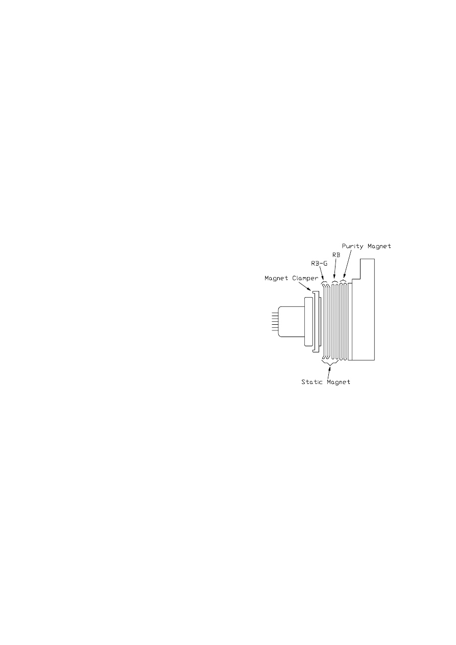
ii. Convergence Adjustment (See Fig.3)
1.
Receive a dotted pattern.
2.
Unfix the convergence magnet clamp and align
red with blue dots at the center of the screen by
rotating (R,B) static convergence magnets.
3.
Align Red/Blue with green dots at the center
of the screen by rotating (RB-G) station con-
vergence magnets.
4.
Fix the convergence magnets by turning the
clamp.
5.
Remove the DY wedges and slightly tilt the
deflection yoke horizontally and vertically to
obtain the good overall convergence.
6.
Fix the deflection yoke by wedges.
7.
If purity error is found, follow “PURITY
ADJUSTMENT” instructions.
(Fig.3)
16
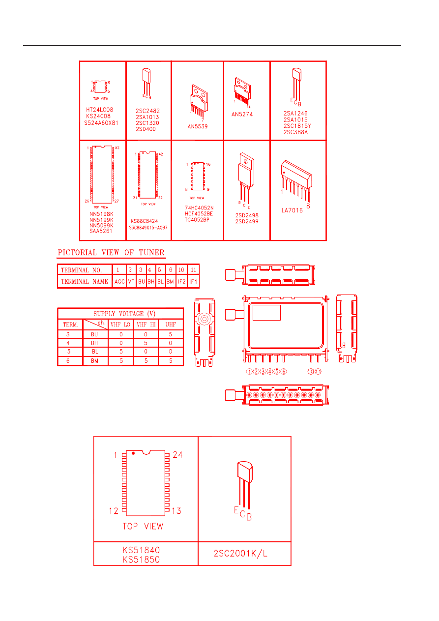
XI. Transistor and IC Identification
A. Main Unit:
B. Remote Control Handset:

17
XII. Schematic Diagram
(Please refer to 21A9-009.pdf)
i.
For A315

18
(Please refer to 21A8-008.pdf)
ii. For 21B8

19
XIII. Component Diagrams
i. Main PCB Component Diagram (Top view)/(Bottom view)
(For A315)
(Please refer to E3701-032010A/B.pdf)

20
ii. Main PCB Component Diagram (Top view)/(Bottom view)
(For 21B8)
(Please refer to E3701-022010A2/B2.pdf)

21
iii. CRT PCB Component Diagram (Top view)/(Bottom view)
(Please refer to E3701-021080.pdf)

22
iv. POWER & AVSIDE & KEY PCB Component Diagram (Top view)/(Bottom view)
(For 21B8)
(Please refer to E3701-011090A2/B2/C2.pdf)

23
v. HANDSET PCB Component Diagram (Top view)/(Bottom view)
(Please refer to E3741-033010.pdf)
24
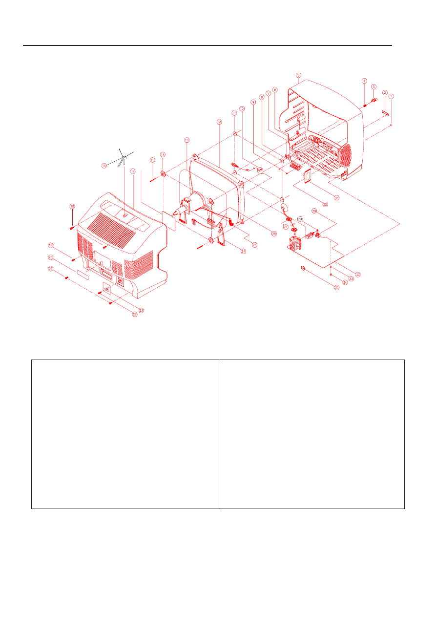
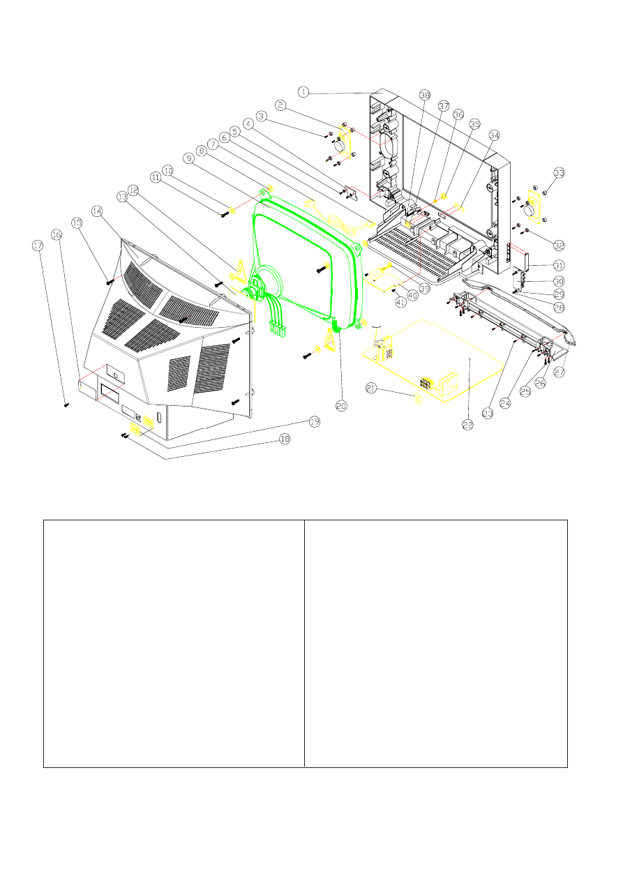
A. TV unit
i. For A315
XIV. Exploded View Diagram and Parts List
Item
Part No.
Description
QTY.
1
389-
Phone Cover Sheet
1
2
486-
NPM
1
3
279-
Power Knob
1
4
477-
Spring Wire CMP
1
5
200-
Cabinet Front
1
6
269-
Lens SNSR RCN
1
7
269-
Lens LED
1
8
277-
Function Knob
1
9
612-
Self-tapping screw
2
10
254-
AC Line Cord Clip
1
11
376-
Rubber Ring
4
12
102-
14” CRT
1
13
E1115-
Coil Degauss
1
14
639-
Special Washer CRT
4
15
614-
Self-tapping screw
4
16
779-
CRT PCB Ass’y
1
17
202-
Cabinet Back
1
18
614-
Self-tapping screw
2
Item
Part No.
Description
QTY.
19
614-
Self-tapping screw
1
20
560-
Model Lable
1
21
614-
Self-tapping screw
2
22
611-
Self-tapping screw
1
23
389-
Cover Plate
1
24
249-
Special Plastic Clip DC
2
25
477-
CRT Spring
1
26
E3421-
Wire Ass’y
1
27
289-
Plastic Ring Protective
2
28
241-
Adaptor for power switch
1
29
250-
Led and sensor holder
1
30
774-
1 Chip Speaker Ass’y
1
31
521-
Felt Paper
2
32
771-
Main PCB Ass’y
1
33
530-
Fire Paper Washer
1
34
612-
Self-tapping screw
1
35
389-
Plate Tuner
1
25
ii. For 21B8
Item
Part No.
Description
Qty.
1
200-
CAB. Front Blk
1
2
Speaker
2
3
615-
S-TAP Screw BWH 4x14
8
4
E3701-
KEY PCB Ass’y
1
5
614-
S-TAP Screw BID 4x10
2
6
254-
CLP CRD PER 8714
1
7
AC Power Line
1
8
376-
Rubber Ring (T=2.0mm)
4
9
21” Colour CRT
1
10
639-
Special Washer CRT
4
11
614-
S-TAP Screw BID 4x30
4
12
249-
Special Plastic Part
2
13
E3701-
CRT PCB
1
14
202-
Back Cabinet Black HI-PS
1
15
614-
S-TAP Screw B/T 5x25mm Black
6
16
560-
Model Label
1
17
614-
S-TAP Screw B/T 4x12mm White
1
18
611-
S-TAP Screw FLT 3x10
2
19
389-
RCA Plate
1
20
477-
SPG+CRT
1
21
389-
Protect Ring
1
Item
Part No.
Description
Qty.
22
E3701-
Mian PCB
1
23
614-
S-TAP Screw BID 4x16
3
24
614-
S-TAP Screw BID 4x10
4
25
614-
S-TAP Screw BID 5x20
4
26
230-
Front Panel (B)
1
27
234-
SUB Panel
1
28
614-
S-TAP Screw BID 4x10
2
29
530-
Fiber Paper
4
30
E3701-
AV PCB
1
31
237-
AV Cover Plate
1
32
379-
Special Rubber Parts SPK
8
33
379-
Special Rubber Parts SPK
8
34
486-
Name Plate
1
35
279-
Power Knob
1
36
477-
SPG+ CRT
1
37
269-
Sensor Lens
1
38
269-
Led Lens
1
39
241-
Power Adapter
1
40
E3701-
Power PCB
1
41
615-
Screw 4x14
2
26
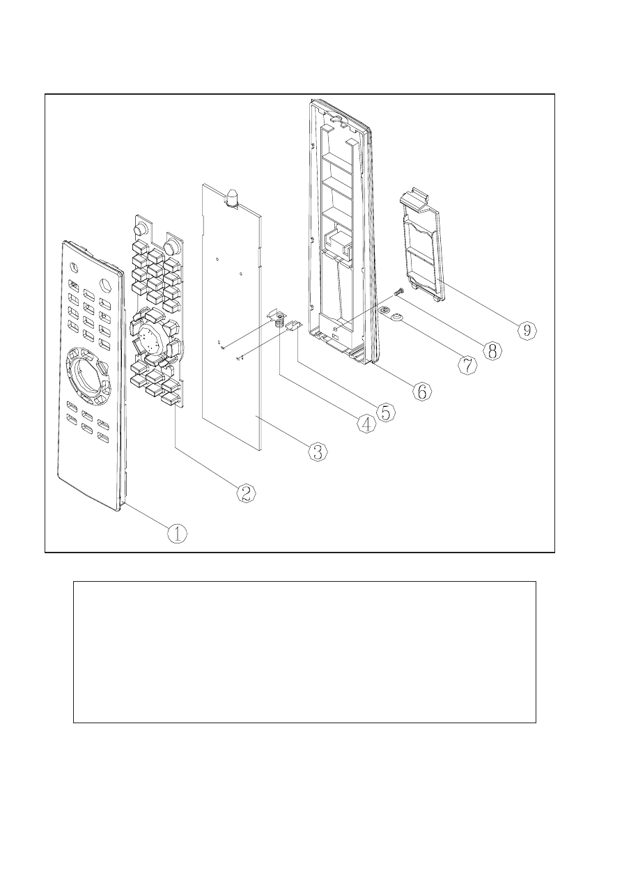
B. Remote handset (790-0035xx-xx)
Ref. No.
Part No.
Description
QTY.
1
201-003501-XXS
CAB TOP
1
2
373-003501-XXY
KYPD RCN
1
3
E3741-
KEY PCB
1
4
472-003301-01B
PLT BAT “-”
1
5
472-003302-01B
PLT BAT “+”
1
6
203-003501-XXS
CAB BM
1
7
610-200206-10
SCREW 2.0x6.0
1
8
477-003301-01
SPG BAT + -
1
9
210-003501-XXS
CV BAT
1
Wyszukiwarka
Podobne podstrony:
service manual 1401
hplj 5p 6p service manual vhnlwmi5rxab6ao6bivsrdhllvztpnnomgxi2ma vhnlwmi5rxab6ao6bivsrdhllvztpnnomg
Oberheim Prommer Service Manual
Korg SQ 10 Service Manual
MAC1500 service manual
Kyocera Universal Feeder UF 1 Service Manual
Proview RA783 LCD Service Manual
indesit witp82euy Service Manual
Glow Worm installation and service manual Hideaway 70CF UIS
Proview PZ456 LCD Service Manual
Glow Worm installation and service manual Ultimate 50CF UIS
ewm2000 service manual
Glow Worm installation and service manual Ultimate 60CF UIS
Proview SH770I LCD Service Manual
M23 Service Manual
Glow Worm installation and service manual Glow micron 60
Konica Minolta QMS 7115, 7118 Service Manual
Honda NSR125 '87 Service Manual
więcej podobnych podstron