
1
Contents
I. Safety Instructions ................................................................................................................................ 2
II. Specifications ....................................................................................................................................... 4
III. Level List of Equipments & Instruments Required for Production ............................................... 6
IV. Applying Adhesive on Main PCB ...................................................................................................... 6
V. Wiring Diagram ................................................................................................................................... 7
VI. Block Diagram ................................................................................................................................... 8
VII. Disassembly ....................................................................................................................................... 9
VIII. Input Signals & Equipments List for Alignment ............................................................................ 9
IX. E2PROM (IC602) Setting .................................................................................................................. 10
X. Electrical Adjustment ........................................................................................................................ 13
XI. Transistor and IC Identification ....................................................................................................... 22
XII. Schematic Diagram ......................................................................................................................... 23
XIII. Component Diagrams ..................................................................................................................... 24
XIV. Packing ............................................................................................................................................ 27
XVI. Exploded View Diagram and Parts List ........................................................................................ 28
A. TV unit .......................................................................................................................................................... 28
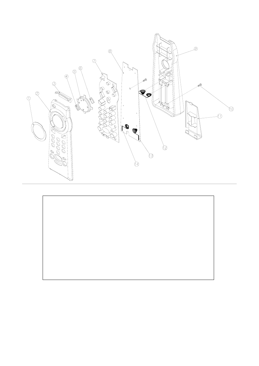
B. Remote handset unit ................................................................................................................................... 29
SERVICE MANUAL
Colour Television Receiver
(UBM CHASSIS)
MODEL:
1401
[A315BN87]

2
PRECAUTIONS DURING SERVICING
1.
In addition to safety, other parts and assemblies are
specified for conformance with such regulations as
those applying to spurious radiation. These must
also be replaced only with specified replacements.
Examples: RF converters, tuner units, antenna
selection switches, RF cables, noise-blocking
capacitors, noise-blocking filters, etc.
2.
Use specified internal Wiring. Note especially:
1) Wires covered with PVC tubing
2) Double insulated wires
3) High voltage leads
3.
Use specified insulating materials for hazardous
live parts. Note especially:
1) Insulating Tape
2) PVC tubing
3) Spacers (insulating barriers)
4) Insulating sheets for transistors
5) Plastic screws for fixing micro switches
4.
When replacing AC primary side components
(transformers, power cords, noise blocking
capacitors, etc.), wrap ends of wires securely about
the terminals before soldering.
5.
Make sure that wires do not contact heat generating
parts (heat sinks, oxide metal film resistors, fusible
resistors, etc.)
6.
Check if replaced wires do not contact sharply edged
or pointed parts.
7.
Make sure that foreign objects (screws, solder
droplets, etc.) do not remain inside the set.
MAKE YOUR CONTRIBUTION TO PROTECT
THE ENVIRONMENT
Used batteries with the ISO symbol
for recycling as well as small
accumulators (rechargeable batteries), mini-batteries
(cells) and starter batteries should not be thrown
into the garbage can.
Please leave them at an appropriate depot.
I. Safety Instructions
WARNING:
Before servicing this TV receiver, read the X-RAY
RADIATION PRECAUTION, SAFETY INSTRUCTION
and PRODUCT SAFETY NOTICE.
X-RAY RADIATION PRECAUTION
1.
Excessively high can produce potentially hazardous
X-RAY RADIATION. To avoid such hazards, the high
voltage must not exceed the specified limit. The
normal value of the high voltage of this TV receiver
is 27 KV at zero bean current (minimum brightness).
The high voltage must not exceed 30 KV under any
circumstances. Each time when a receiver requires
servicing, the high voltage should be checked. The
reading of the high voltage is recommended to be
recorded as a part of the service record, It is
important to use an accurate and reliable high
voltage meter.
2.
The only source of X-RAY RADIATION in this TV
receiver is the picture tube. For continued X-RAY
RADIATION protection, the replacement tube must
be exactly the same type as specified in the parts
list.
3.
Some parts in this TV receiver have special safety
related characteristics for X-RADIATION protection.
For continued safety, the parts replacement should
be under taken only after referring the PRODUCT
SAFETY NOTICE.
SAFETY INSTRUCTION
The service should not be attempted by anyone
unfamiliar with the necessary instructions on this TV
receiver. The following are the necessary instructions
to be observed before servicing.
1.
An isolation transformer should be connected in the
power line between the receiver and the AC line
when a service is performed on the primary of the
converter transformer of the set.
2.
Comply with all caution and safety related provided
on the back of the cabinet, inside the cabinet, on the
chassis or picture tube.
The lightning flash with arrowhead symbol,
within an equilateral triangle, is intended to alert
the user to the presence of uninsulated “dangerous
voltage” within the product’s enclosure that may
be of sufficient magnitude to constitute a risk of
electric shock to persons.
The exclamation point within an equilateral
triangle is intended to alert the user to the
presence of important operating and maintenance
(servicing) instructions in the literature accom-
panying the appliance.
CAUTION: TO REDUCE THE RISK OF ELEC-
TRIC SHOCK, DO NOT REMOVE COVER (OR
BACK). NO USER-SERVICEABLE PARTS
INSIDE. REFER SERVICING TO QUALIFIED
SERVICE PERSONNEL ONLY.
CAUTION
RISK OF ELECTRIC SHOCK
DO NOT OPEN
3
PRODUCT SAFETY NOTICE
Many electrical and mechanical parts in this TV
receiver have special safety-related characteristics.
These characteristics are offer passed unnoticed by
visual spection and the protection afforded by them
cannot necessarily be obtained by using replacement
components rates for a higher voltage, wattage, etc.
The replacement parts which have these special
safety characteristics are identified by
marks on
the schematic diagram and on the parts list.
Before replacing any of these components, read the
parts list in this manual carefully. The use of
substitute replacement parts which do not have the
same safety characteristics as specified in the parts
list may create shock, fire, X-RAY RADIATION or
other hazards.
Good earth ground
such as the water
pipe, conductor, etc.
Place this probe
on each exposed
metallic part
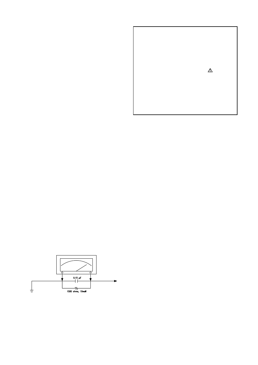
AC VOLTMETER
AC Leakage Current Check
3.
To avoid a shock hazard, always discharge the
picture tube's anode to the chassis ground before
removing the anode cap.
4.
Completely discharge the high potential voltage of
the picture tube before handling. The picture tube is
a vacuum and if broken, the glass will explode.
5.
When replacing a MAIN PCB in the cabinet, always
be certain that all protective are installed properly
such as control knobs, adjustment covers or shields,
barriers, isolation resistor networks etc.
6.
When servicing is required, observe the original lead
dressing. Extra precaution should be given to assure
correct lead dressing in the high voltage area.
7.
Keep wires away from high voltage or high tempera
ture components.
8.
Before returning the set to the customer, always
perform an AC leakage current check on the exposed
metallic parts of the cabinet, such as antennas,
terminals, screwheads, metal overlay, control shafts,
etc., to be sure the set is safe to operate without
danger of electrical shock. Plug the AC line cord
directly to the AC outlet (do not use a line isolation
transformer during this check). Use an AC voltmeter
having 5K ohms volt sensitivity or more in the
following manner.
Connect a 1.5K ohm 10 watt resistor paralleled by a
0.15µF AC type capacitor, between a good earth
ground (water pipe, conductor etc.,) and the exposed
metallic parts, one at a time.
Measure the AC voltage across the combination of
the 1.5K ohm resistor and 0.15 uF capacitor. Reverse
the AC plug at the AC outlet and repeat the AC
voltage measurements for each exposed metallic
part.
The measured voltage must not exceed 0.3V RMS.
This corresponds to 0.5mA AC. Any value exceeding
this limit constitutes a potential shock hazard and
must be corrected immediately.
The resistance measurement should be done
between accessible exposed metal parts and power
cord plug prongs with the power switch "ON". The
resistance should be more than 6M ohms.
4
No.
Items
Instruction
Typical
Limit
Unit
1
Video sensitivity
For 30dB S/N
VL
≤
45
≤
48
VH
≤
45
≤
48
dBuV
U
≤
48
≤
51
2
FM sound sensitivity
For 30dB S/N
30
≤
35
dBuV
3
Synchronizing sensitivity
For RF transmission
25
≤
30
dBuV
4
Color sensitivity
For RF transmission
32
≤
40
dBuV
5
Teletext sensitivity
TV screen refreshes 40 times
number of mistakes
≤
8
N/A
N/A
dBu
6
Minimum NICAM threshold
Without crackline noise
N/A
N/A
dBu
7
AGC static characteristic
Accept. Picture/tone repr.
103
≥
100
dBu
8
Selectivity
Adjacent sound carrier
40
≥
35
Below adjacent sound carrier
35
≥
30
dB
Adjacent picture carrier
50
≥
40
Up adjacent picture carrier
45
≥
30
9
IF rejection
55
≥
50
dB
10
Image rejection
VHF
55
≥
50
dB
UHF
50
≥
45
11
AFT pull-in range
M/N
N/A
N/A
MHz
DK/BG
±1.5
≥|
±1.0|
12
Chroma sync pull-in range
±500
≥
|±200|
Hz
13
Color killer function
-25
≤
-16
dB
14
DC restoration
3
≤
10
%
15
Resolution
Horizontal
PAL/SECAM
320
≥
300
NTSC
270
≥
250
Vertical
PAL/SECAM
410
≥
400
lines
NTSC
320
≥
300
16
Overscan
Cross hatch signal
93
90~96
%
17
Linearity
Horizontal
7
≤
10
%
Vertical
6
≤
8
%
18
Pattern distortion
1.5
≤
3
%
19
Picture position
In all direction
±3
≤
|±6|
mm
20
Raster rotation
In all direction
4
≤
6
mm
21
Convergence error
0.4
≤
0.6
%
22
White balance (8700°K)
X
0.288
0.288±0.015
Y
0.298
0.298±0.015
/
23
Maximum full white
At picture tube center
110
100
cd/m
2
24
H sync pull-in range
±500
≥
|±200|
Hz
25
V sync pull-in range
7
≥
6
Hz
26
Anode voltage
23
≤
27.5
KV
27
Audio frequence response
±3dB ref. to 1KHz
0.2~8
0.2~8
KHz
28
Audio output power
1KHz 10% THD
2.7
≥
2.5
W
50KHz DEV. (BG/I/DK)
25KHz DEV. (M/N)
II. Specifications
1. Power supply
TV: AC 220 V, 50Hz
Remote control battery: 3V (UM-3X2)
2. TV system
RF input
:
PAL BG/DK, SECAM BG/DK
Video input :
PAL/SECAM/NTSC 3.58/NTSC 4.43
3. Receiving channels
VHF-L :
E2-S10
VHF-H :
E5-S41
UHF
:
E21-E69
4. Intermediate frequencies Picture :
38.9MHz
5. Scanning
Horizontal (Hz) :
15625/15750
Vertical (Hz)
:
50/60
6. Color picture tube:
14” North(1) hemisphere Bv=+0.35G±0.2G
7. Operating temperature
Fulfil all specifications: 15°C ~ 35°C
Accept picture/tone reproduction: 5°C ~ 45°C
8. Operating relative humidity
Fulfil all specifications: 45% ~ 75%
Accept picture/tone reproduction: 15% ~ 90%
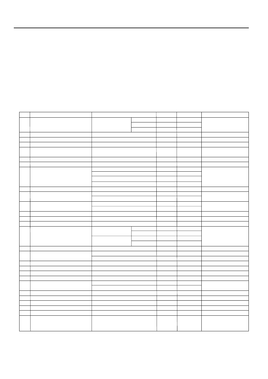
9. Electrical & Optical Specification:
5
Test Condition
1
Picture Modulation
87.5%
2
Sound Modulation
27KHz Dev. For DK/I/BG
15KHz Dev. For M/N
3
Picture to Sound Ration
10dB
4
Sound Artificial Load Resistor
8 ohm
5
Video signal
White and black
(three white & two black)
6
Audio signal
1KHz sine wave 0.5Wrms
Convergence error test point on
7
Conditions of the TV setting:screen
A. Switch TV on and let it warm up for more than 30 minutes.
B. Connect RMS volt meter to speaker terminals and adjust theTV volume to get 500mW RMS power at each terminal.
C. Place the MINOLTA CA-100 test probe to white part of the screen,adjust the contrast until a reading of 80cd/m
2
is obtained.
D. Place the MINOLTA CA-100 test probe to black part of the screen,adjust the brightness until a reading of 2cd/m
2
is obtained.
E. Repeat step C & D until the exact luminance values is obtained or the nearest possible values you can get.then record the
luminance values & R.G.B gun voltage values at the same time. and take the largest values for measurement referenct.
F. Input standard color bar(100/0/75/0),then adjust the colour.until the waveforms at the blue gun of same level is obtained.
W
H
1/9H
1/9W
+P8
P5+
+P7
P6+
+P1
+P3
+P4
P2+
+P0
No.
Items
Instruction
Typical
Limit
Unit
29
THD
Po=0.5W 1KHz
1
≤
3
%
30
Signal to buzz ratio
42
≥
40
dB
31
Minimum volume hum
6
≤
10
mVrms
32
Maximum woofer output power
N/A
N/A
W
33
Woofer audio freqency response
±3dB ref. to 80Hz AV mode
N/A
N/A
Hz
34
Bass control range
100Hz ref. to 1KHz AV mode
N/A
N/A
dB
35
Treble control range
10KHz ref. to 1KHz AV mode
N/A
N/A
dB
36
Balance
Center
N/A
N/A
Max.
N/A
N/A
dB
Min.
N/A
N/A
37
Volume control curve
N/A
/
38
Video input level
1.0
1±0.2
Vpp
39
Audio input level
0.5
0.5±0.3
Vrms
40
Video output level
1.0
1±0.2
Vpp
41
Audio output level
0.5
0.5±0.2
Vrms
42
Power consumpution
Operating
70
≤
80
W
(AT 220V AC)
Stand by
10
≤
15
W
43
IR receiving distance
±30°
6
≥
4
m
44
X-ray radiation
<0.1
≤
0.5
mR/h
45
Dielectric strength
AC 3KVrms 2 sec.
3
≤
5
mArms
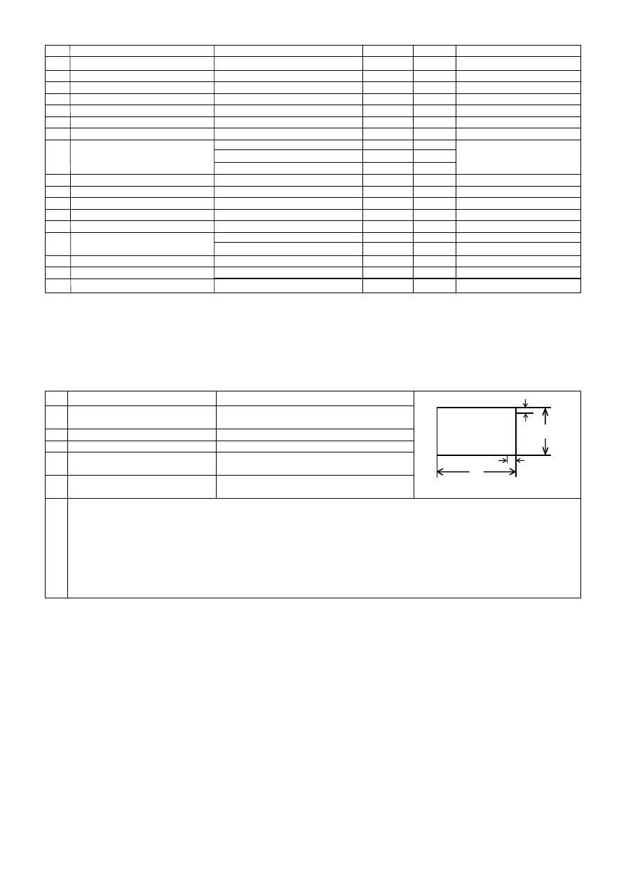
6
No. Designation
Requirement
Reference Model
Remark
1
Pattern Generator
System of output signal:
PHILIPS
RF out: PAL BG/SUB/DK/I,
PM5518-TN
SECAM B/G/D/K, NTSC M
PM5418-TN
Video out: NTSC 4.43/3.58 PAL 60Hz
2
Digital voltmeter
Input Resistance 10M
FLUKE 45
3
Withstanding
Withstanding Voltage:
KIKUSUI TOS 8650
Irresistible Voltage Measure
Voltage Tester
AC 1.5KV, 5KV/0-5KV ± 3%
Cut-off current: AC 0-2mA,
20mA / continuously Adjustable
4
Insulation Tester
Test voltage:1000V. 500V
KIKUSUI TOS 7100L
5
Sine wave Signal
Frequency Range: 0.1~140MHz
LEADER 3216
For generating IF Signal
Generator
( Precision:10KHz )
Level Range: -20~126dB
6
Oscilloscope
Frequency response: 20MHz or above
7
CRT Color
MINOLTA CA-100
For White Balance Adjustment
Analyzer
8
DC Regulated
Max output Voltage 14V
Supply DC power
Power Supply
9
Color Monitor
AV receiving system: Should include
Same model (of TV set)
For operation check
all the AV output system of the
as the products
For resolution check
products at least.
For Skew Check
10 Audio Signal
Frequency of output signal:
KENWOOD AG-203A
For generating audio signal
Generator
20Hz-20kHz
III. Level List of Equipments & Instruments Required for Production
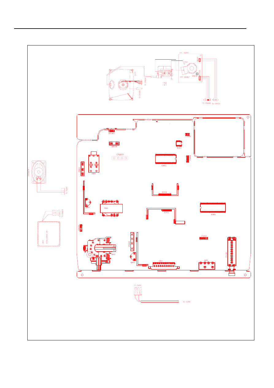
IV. Applying Adhesive on Main PCB
For 1401[A315BN87] model
7
V. Wiring Diagram
For 1401[A315BN87] model

8
VI. Block Diagram
For 1401[A315BN87] model
9
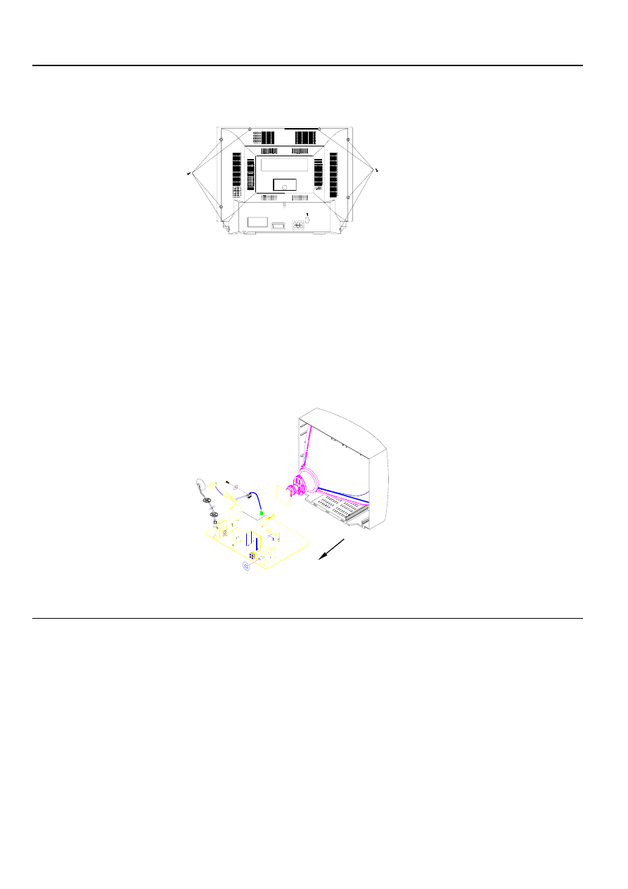
VII. Disassembly
In case of trouble, etc., necessitating disassemble, please disassemble in the order shown in the illustrations. Reas-
semble in the reverse order.
1.
Removal of the Back Cover
2.
Removal of the MAIN PCB
a. Remove the screws.
b. Slide out the TV chassis slightly; pull up the connector of AC cord from PCB; pull up the CRT PCB from
CRT.
c. Remove the anode cap from the picture tube. To avaid a shock hazard, be sure to discharge the picture
tube’s anode to the chassis ground before removal.
d. Take out the TV chassis.
VIII. Input Signals & Equipments List for Alignment
A.
Equipments List
1. Pattern Generator
2. Digital Voltmeter
3. High Voltage Meter
4. Sine Wave Signal Generator
5. Demagnetizer
6. Personal Computer (486)
7. DC Regulated Power Supply
8. Oscilloscope
9. CRT Colour Analyzer
B. Input Signals
1. Philips Pattern
2. Color Bar
3. Cross Hatch
4. Grey Scale Bar
5. Monoscope Pattern
6. Moving Picture With Sound

10
DIGIT 1:
1
OQSS
0 = QSS OFF
1 = QSS ON
2/3
MODE
OSVD
OAV2
TV/AV
0
0
TV/AV1/AV2
0
1
TV/AV1/AV2/SVD
1
1
Digit 2:
4
OCHIL
0 = CHILD LOCK NOT AVAILABLE
1 = CHILD LOCK AVAILABLE
5
OWOO
0 = WOOFER NOT AVAILABLE
1 = WOOFER AVAILABLE
6
OUHF
0 = ALL BAND (VL, VH, UHF)
1 = UHF ONLY
Digit 3:
7
OSYS1
0 = SINGLE COLOR SYSTEM (PAL) AVAILABLE
1 = MULTI COLOR SYSTEM (AUTO/PAL) AVAILABLE
8
OSYS2
0 = MULTI SYSTEM SECAM NOT AVAILABLE (TV & AV)
1 = MULTI SYSTEM SECAM AVAILABLE (TV & AV)
9
OSYS3
0 = MULTI SYSTEM NTSC NOT AVAILABLE (TV)
1 = MULTI SYSTEM NTSC AVAILABLE (TV)
Digit 4:
TUNER IF
SETUP:
OTUN1
OTUN2
OTUN3
34.47
MHz
0
0
0
36.875
MHz
0
0
1
38
MHz
0
1
0
38.9
MHz
0
1
1
39.5
MHz
1
0
0
45.75
MHz
1
0
1
Digit 5:
13
OBL
0
= BILINGUAL (MAIN/SUB) NOT AVAILABLE
1
= BILINGUAL (MAIN/SUB) AVAILABLE
14
OSND1
0
= MULTI SIF SYSTEM AVAILABLE
1
= SINGLE SIF SYSTEM AVAILABLE
15
OSNDB
0
= SIF [BG] NOT AVAILABLE
1
= SIF [BG] AVAILABLE
The “option setup” is shown as following:
Every digit represents the lower 3 bits of a nibble of 4 bytes in EEPROM, and each of the bits stands
for an option function, the option bits listed below:
OPTION MENU
01234567
01234567
BIT7
BIT6
BIT5
BIT4
BIT3
BIT2
BIT1
BIT0
BYTE1
NU
OQSS
OSVD
OAV2
NU
OCHIL
OWOO
OUHF
BYTE2
NU
OSYS1
OSYS2
OSYS3
NU
OTUN1
OTUN2
OTUN3
BYTE3
NU
OBL
OSND1
OSNDB
NU
OSNDI
OSNDD
OSNDM
BYTE4
NU
ORUSS
OBB
OTVO
NU
OCHIT
OCHIS
OENG
BYTE5
NU
OMSIF
OBGSIF
OISIF
NU
ODKSIF
OCHAN2
OCHAN1
IX. E
2
PROM (IC602) Setting
A.
Option Code
The option code listed below is for selection of different TV systems, features and functions, the code is preset
in factory, in case of changing the EEPROM, the option code will not be the same as before. In this case, it is
necessary to adjust the option code again. How to set the option code by hand is described in “method to
enter into SERVICE MENU and ADJUST MENU”. Please refer to “V. Electrical Adjustment”.
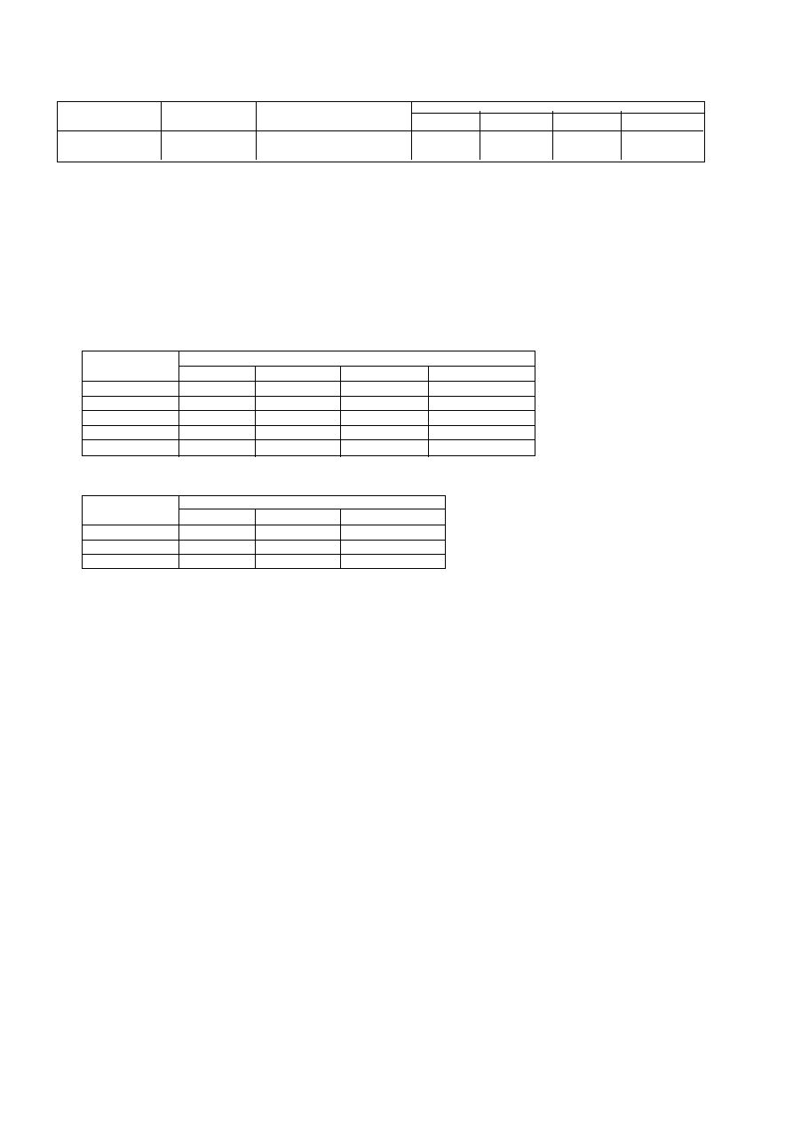
Model
Option code
1401[A315BN87]
54631263

11
Digit 6:
16
OSNDI
0
= SIF [I] NOT AVAILABLE
1
= SIF [I] AVAILABLE
17
OSNDD
0
= SIF [DK] NOT AVAILABLE
1
= SIF [DK] AVAILABLE
18
OSNDM
0
= SIF [M] NOT AVAILABLE
1
= SIF [M] AVAILABLE
Digit 7:
19
ORUSS
0
= RUSSIAN OSD NOT AVAILABLE
1
= RUSSIAN OSD AVAILABLE
20
OBB
0
= BLUE BACK NOT AVAILABLE
1
= BLUE BACK AVAILABLE
21
OTVO
0
= SCART MONITOR OUTPUT
1
= SCART TV OUTPUT
Digit 8:
22
OCHIT
0
= TRADITIONAL CHINESE (HK) OSD NOT AVAILABLE
1
= TRADITIONAL CHINESE (HK) OSD AVAILABLE
23
OCHIS
0
= SIMPLE CHINESE (CHINA) OSD NOT AVAILABLE
1
= SIMPLE CHINESE (CHINA) OSD AVAILABLE
24
OENG
0
= ENGLISH OSD NOT AVAILABLE
1
= ENGLISH OSD AVAILABLE
Digit 9:
25
OMSIF
0
= M SIF INTERNAL
1
= M SIF EXTERNAL
26
OBGSIF
0
= BG SIF INTERNAL
1
= BG SIF EXTERNAL
27
OISIF
0
= I SIF INTERNAL
1
= I SIF EXTERNAL
Digit 10:
28
ODKSIF
0
= DK SIF INTERNAL
1
= DK SIF EXTERNAL
29/30 CHANNEL
NUMBER
0CHAN2
0CHAN1
100
0
0
200
0
1
254
1
0
NU: NOT USED
RES: RESERVED
B. Data Setting
The data setting item B~D is the initialization data preset in the EEPROM before adjustment in case of
changing the EEPROM, please set the data to initialization data listed below before adjustment. How to set
the data by hand is described in “method to enter into SERVICE MENU and ADJUST MENU”. Please refer
to “V. Electrical Adjustment”.
Parameter
Value(DEC)
Remark
Parameter
Value(DEC)
Remark
SUB BRI
63
HOR.POS60
13
CUTOFF R
63
VER.POS60
0
CUTOFF G
63
VER.H60
81
Remark6
CUTOFF B
63
VER.LIN60
40
Remark1
DRIVE R
63
VER.S C60
20
Remark1
DRIVE B
63
SUBTINT
16
AFT ADJ
55
AV S TINT
16
RFAGCDP
45
C-Y
1
Remark2
SECAM BL
0
HOR.VCO
52
RGB LIMIT
0
VIF.VCO
26
HOR.POS
13
ISUD5
0
Remark3
VER.POS
0
ISUD4
1
VER.HEI
84
Remark5
ISUD3
1
VER.LIN
40
Remark1
CONTR 32
0
VER.S CUR
20
Remark1
RI CUTOF
1
Remark4
12
C.
Intelligent picture control (I.P.C) DATA SETTING
D.
AFT Data Setting
Remark: This table of AFT DATA setting is only for:
SAMSUNG tuner: TECC0949VG28B, TECC7949VG28B and WITTIS tuner: UVS1051-CW1/UVS1051-NEW.
Control
Value
Natural
Sharp
Cinema
Personal
Brightness
16
24
12
16
Contrast
24
32
16
24
Colour
16
20
16
16
Sharpness
16
24
16
16
Tint
16
16
16
16
Description
Value
VHFL
VHFH
UHF
Low
120
56
35
Middle
97
40
31
High
131
76
90
Remark1:
For different CRT, the following data are recommended to change for better performance before
alignment. These Data Settings are listed as following:
Note: Please refer to the CRT conversion table for other CRT.
Remark2:
C-Y=0 For AMFxx models (use NN5198K)
C-Y=1 For other models (use NN5199K or NN5099K)
Remark3:
ISUD5 must set to “0”,Please check ISUD5 after Read 5198.
Remark4:
Some version MCU has not this item.
Remark5:
Ver. Hei: 50
Remark6:
Ver. H60: 50
CRT
CRT Type No.
Value
VER.LIN
VER.SCUR VER.LIN60
VER.SC60
14” BMCC
E6101-094001
A34JQQ90X94 N1
38
16
36
16

13
Note: Please refer to the CRT conversion table for other CRT.
b. Adjustment Step
Adjust VR901 to make the read-out on the Voltmeter to be +B±0.3V.
ii. Method to enter into SERVICE MENU and ADJUST MENU
a. Turn on the Main Power Switch, then press volume buttons both "+" and "-" simultaneously for over 5 seconds,
the "KWTUA SERVICE" will be displayed on the screen.
b. The “KWTUA SERVICE” menu is indicated with each item on
the screen. The item can be selected by pressing channel “ ”
and “ ” keys.
c. Selecting “Read 5198”, press “MENU/OK” key (or press “OK”
key on the remote handset) to read IC NN5099K/NN5198K DATA
in order to operate the TV set. On-screen display will be shown as :
Press “MENU/OK” key (or press “OK” key on the remote handset)
to confirm Read 5198. Press “M” key on the remote handset to exit.
Note: 1. Many standard data are already pre-set in the EEPROM inside IC NN5198K or NN5099K by the IC
manufacturer. During manufacturing the TV set, it is necessary to read those data stored in EEPROM
of IC NN5198K or NN5099K and memorize it in external EEPROM. By doing so, some alignment can
be omitted, or the data memorized in the external EEPROM can be changed according to the situation.
Please note that according to the specification, the operation of “reading” data from the EEPROM inside
NN5198K or NN5099K only can be done 1000 times. When changing IC201 (NN5198K or NN5099K)/
IC602 (EEPROM) or before adjusting, it is necessary to read NN5198K or 5099K data one time.
2. “CNT:X” means number of times that the data stored in the EEPROM of NN5198K or NN5099K has
been read. For example, CNT:19, it means the data stored in the EEPROM of NN5198K or NN5099K
has been read 19 times.
d. Selecting “Option”, press “OK” key then input the option code by number keys on the remote handset
according to the “Option code”. After changing “OPTION”, the TV set must be set to standby and power on
again, then enter into “SERVICE MENU”.
e. Select “Adjustment”, press “OK” key on the remote handset. The “ADJUST MENU” is indicated with each
parameter on the screen. Pressing channel “
” and “
” keys can select the responding parameter. The
parameter value can be changed by pressing volume “+” and “-” keys. Press “OK” key to exit.
f. Select “Other Adj.”, press “MENU/OK” (or press “OK” key on the remote handset), On-screen display will be
shown as following:
X. Electrical Adjustment
A. Chassis Adjustment
i.
+B Voltage Alignment
a. Preparation Procedure
1). Receive standard colour bar signal.
2). Press key "I.P.C." to select “Natural” mode.
3). Connect digital voltmeter between
of C403 (For 21A8/25A9/29A9) or C416 (For 21A9) and GND.
4). +B voltage.
Model
CRT
CRT Type No.
+B
1401[A315BN87]
E6101-094001
A34JQQ90X94 N1 BMCC
110V
KWTUA SERVICE
Adjustment
Option
xxxxxxxx
Confirm Read ??? X
Other Adj.
KWTUA SERVICE
Adjustment
Option
xxxxxxxx
Read 5198
CNT: X
Other Adj.
14
1). Production
The function of ”Production” is for production aging purpose. When no RF signal input and if it is set
to “on”, the TV set will not be blue back and standby shortly. When the TV set is finished, it must be
set to “off”. If it is set to “on”, a character “P” will appear on the top of the screen when changing
channel, this means that it is set for production purpose. By pressing the volume “+” and “-” keys,
“Production” can be set to “off” or “on”. By pressing the “MENU/OK” in the TV set or “M” key on the
remote handset, it will exit the menu.
2). AFT-Step
Selecting “AFT-Step” to set AFT DATA, press “OK”
key to enter, On-screen display will be shown as:
Use channel “
” and “
” keys to select the parameter, the parameter value can be changed by
pressing volume “+” and “-” keys. See “AFT data setting”. Press “M” key on the remote handset or
“MENU/OK” key in TV set to exit.
3). IPC
Selecting “IPC” to set picture mode data, press “OK” key to
enter, the picture mode data is indicated with each parameter
on the screen. Press “I.P.C.” key to select picture mode,
select the parameter and change the parameter value.
When this picture mode data is ok, press “OK” key to store,
the parameter value below will display “Stored”. When all
picture mode data is being stored, press “MENU” key to exit.
iii. Adjustment of T101(31.9MHz trap) and AFC
A. Adjustment for T101(31.9MHz trap) (for using T101 models)
1. Turn on the main power switch.
2. Apply 100dBµv 31.9MHz signal between IF input pin and GND of the TUNER on main PC board.
3. Put the probe of oscilloscope to SA102 pin1 and GND.
4. Adjust T101 until the waveform in oscilloscope to minimum.
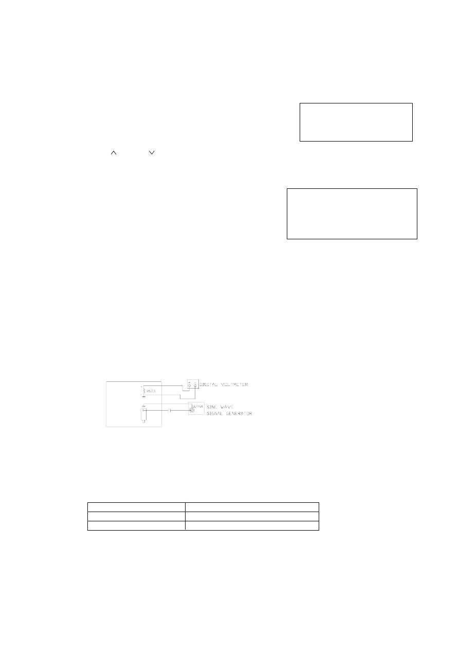
B. Adjustment of AFC
a. Preparation procedure
1. Turn on the main power switch.
2. Set digital voltmeter at DC, then connect it’s probe across of R603 and GND.
3. Apply 100dBµV IF signal between IF input pin and GND of the TUNER on main PC board (see Fig.1).
b. Adjustment Step
Adjust the “AFT ADJ” DATA until the meter indicates 2.4±0.1V.
c. AFC Check.
After adjustment, it is necessary to confirm the DC voltage across R603 when Changing the RF output
frequency of pattern generator (PM5518) by ±o.1MHz, the DC voltage shoud be as:
Remark: IF=38.0MHz
If the result is not satisfactory, repeat adjustment step "b. Adjustment Step" until correct voltage is obtained.
d. Press “OK” key to store.
e. press “MENU” key to exit.
KWTVA OTHER
Production
off
AFT-Step
IPC
KWTVA AFT-STEP
09-08
Band
VHFL
Low
120
Middle
97
High
131
(Fig.1)
RF FREQUENCY
DC VOLTMETER INDICATION
IF+0.1MHz
1.2±0.5V
IF-0.1MHz
3.3±0.5V

15
iv. Adjustment for H position and V position, V-height and V linearity.
a. Receive
pattern signal (PAL).
b. Enter ADJUST MENU.
1. Adjust value of HOR.POS to get a good H position picture.
2. Adjust value of VER.HEI to get a normal picture.
3. Adjust value of VER.POS to get a good V position picture.
4. Normal VER.LIN and VER.S CUR doesn’t need adjustment. If V linearity is not good, please adjust
value of VER.LIN and VER.S CUR to get a good V linearity picture.
c. Receive
pattern signal (NTSC).
d. Enter ADJUST MENU
1. Adjust value of HOR.POS60 to get a good H position picture.
2. Adjust value of VER.H60 to get a normal picture.
3. Adjust value of VER.POS60 to get a good V position picture.
4. Normal VER.LIN60 and VER.SC60 doesn’t need adjustment. If V linearity is not good, please adjust
value of VER.LIN60 and VER.SC60 to get a good V linearity picture.
e. Press “OK” key to store.
f. press “MENU” key to exit.
v.
Adjustment for TV TINT (TV picture) and AV TINT (AV picture)
a. Receive a NTSC color bar Signal from AV.
b. Enter ADJUST MENU
Adjust the value of AV S TINT until the waveform of Oscilloscope is shown as above.
vi Adjustment for SECAM BL (for use NN5198K model)
a. Receive a SECAM dot pattern signal from RF.
b. Press key “I.P.C” to select “NATURAL” status.
c. Put the Probe of Oscilloscope to “B-out” Terminal of IC201 Pin12 and GND.
(Probe: 10:1, Oscilloscope VOLTS / DIV: 20mv / DIV.)
d. Enter ADJUST MENU.
Adjust Value of SECAM BL until
V is smallest (see Fig.2).
e. Press “OK” key to store.
f. press “MENU” key to exit.
vii. Adjustment for RF AGC
a. Receive RF signal (62±3dBµV).
b. Enter into ADJUST MENU.
c. Pressing channel “
” and “
” keys on the remote handset and on-screen display will be shown as
following: RFAGCDP XX
d. Press volume "+" or "-" on the remote handset to change the value of RFAGCDP until snow noise on
the screen just disappears.
e. Press “OK” key to store.
f.
press “MENU” key to exit.
viii. Adjustment for Sub-brightness
a. Receive MONOSCOPE pattern.
b. Press key “I.P.C” on the remote handset to set Brightness and Contrast at natural state.
c. Enter into ADJUST MENU.
d. Pressing channel “
” and “
” on the remote handset, the display on screen will be: SUB BRI XX
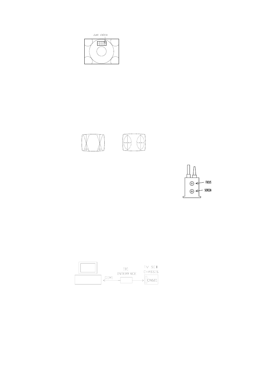
e. Press volume “+” or “-” on the remote handset to change the value of SUB BRI until eight and half of
portions indicated in Fig.3 is just visible.
(Fig.2)
16
f.
Press “OK” key to store.
g. press “MENU” key to exit.
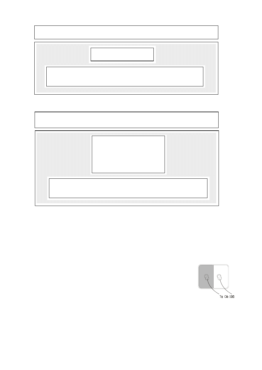
ix. Pincushion Correction
1. Receive crosshatch pattern. (croix centrale pattern).
2. Adjust keystone correction control VR1303/VR480 to obtain symmetrical
pattern about horizontal center as shown in Fig.4a.
3. Adjust pillow correction control VR1301/VR482 to obtain vertical
straight lines on screen as shown in Fig.4b.
4. Adjust horizontal width control VR1302/VR481 to desired picture width.
5. Adjust top correction control VR483 to obtain proper top picture on the screen.
6. Control contrast brightness from mini to maxi, check the picture of pattern, repeat step 3-5 until a
desired picture is obtained.
x.
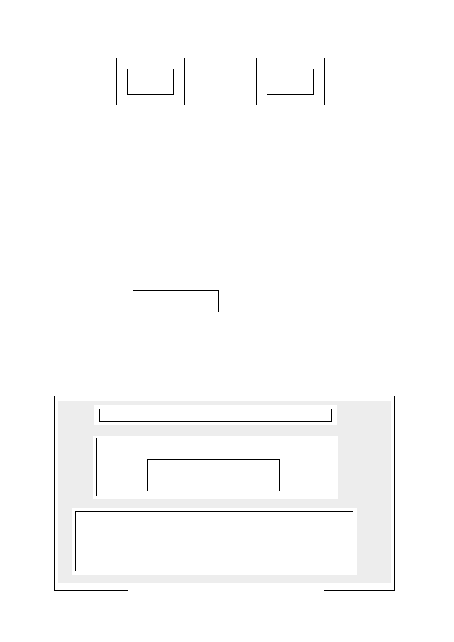
Adjustment for FOCUS (See Fig.5)
a. Press key "I.P.C." on the remote handset to set Brightness and
Contrast both at normal position.
b. Adjust knob "FOCUS" on FBT to make the picture on the screen
to be the most distinct.
xi. Adjustment with computer.
INTRODUCTION
"UBM" is an adjustment program for colour TV set which use NN5099K/NN5198K as the chroma processing IC.
This program can change the TV set data of different function though IIC interface and provides Auto
Adjustment of the White-Balance by using the Colour Analyzer (MINOLTA CA-100).
SET UP
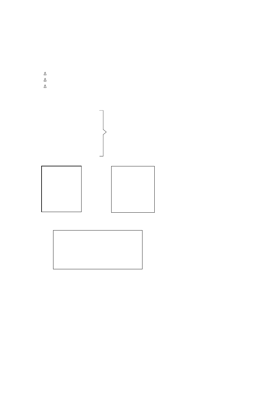
1. The computer must be installed with the software program named UBM.
2. Power on the TV set and the computer.
3. Connect the computer and connect the adjustment cable from the computer to the TV chassis at
location CN601 as following:
4. C:\ cd UBM ENTER
5. C:\ cd UBM >UBM ENTER
(Fig.3)
(Fig.4a)
(Fig.4b)
(Fig.5)
17
ZHONG SHAN KAWA ELECTRONIC RESEARCH & DEVELOPMENT CENTER
AUTO ADJUSTMENT FOR COLOUR TV SET (VERSION V1.00 FOR )
The screen will display:
Your Computer is: PC/AT 80386 33MHz
If Information of Your Computer not Right, Please Run SELF TEST.
Use , Key to Select Options, Enter to Confirm or Esc to Quit.
↑
↑
(A) WB AUTO ADJUST
(B) SETUP EEPROM
(C) READ EEPROM
(D) PC SELF TEST
(E) WB PARMS SETUP
(F) EXIT TO DOS
6. Use keys
in the computer to select the software program named UBM, then press “enter” key in
the computer. The screen will display:
ZHONG SHAN KAWA ELECTRONIC RESEARCH & DEVELOPMENT CENTER
AUTO ADJUSTMENT FOR COLOUR TV SET (VERSION V1.00 FOR UBM)
↑
↑
Your Computer is: PC/AT 80386 33MHz
If Information of Your Computer not Right, Please Run SELF TEST.
Use , Key to Select Options, Enter to Confirm or Esc to Quit.
↑
↑
CPU Program Name:
UBM UBMT
This is the main menu for adjustment and the different data can be changed and viewed.
It consists of following functions.
(A) WB AUTO ADJUST
(D) PC SELF TEST
(B) SETUP EEPROM
(E) WB PARMS SETUP
(C) READ EEPROM
(F) EXIT TO DOS
(A).
WB AUTO ADJUST
Before enter to WB AUTO ADJUST, make sure the WB PARMS SETUP (E) is fulfil your adjustment
requirement.
Procedure:
1. Check WB setup and to define standard and tolerance.
2. Connect the colour Analyzer (Minolta CA-100) to the computer (COM 1).
3. Turn on the TV set and receive the White-Grey signal.
4. Connect the adjustment cable to the TV at location CN601.
5. Press Space Bar, the computer will display "Please adjust screen Voltage,
space Bar to continue". Now change to TV service mode and adjust the screen
voltage until ahorizontal line is just visible on the screen, then back to normal mode
by pressing “Space” bar in the computer.
6. Put the colour probe 1 to the low luminance side and colour probe 2 to the high luminance side of
the screen. (It is better to place near the center of the screen.)
7. Press Space Bar to start WB adjustment.
P1
P2
18
If the WB adjustment is success, the computer will display "Finished to adjust white Balance and show all
value and adjustment time used. Then the user must put off the adjustment cable from the TV IIC interface
now. Then repeat from the step 3 for another TV set adjustment.
If the adjustment cannot be finished within your presetted time limit, the computer will display "Sorry,
adjustment stopped!" and the adjustment is failed. It is better to call technician to check the TV hardware
if the adjustment failed several times.
(B).
SETUP EEPROM
The function: "SETUP EEPROM" is used for writing a date file to the TV set's EEPROM.
Before to do this process, it is needed to read the date file from a TV set first, otherwise the computer
will display the warning message and back to main menu.
If you already have had Previous EEPROM file, the program will ask for select:
a) (24C02)
b) UBM/UBMT (24C04)
c) (24C08)
After EEPROM SIZE selection, it will list the data files which are the same size as the user select, the
user now need to select one of the files, and press «Enter» to confirm writing the data to TV set's EEPROM.
* Remark:
"SETUP EEPROM" will overwrite all the data in EEPROM. Please make a data backup before
to do this process.
Channel File not Found!
Press enter to Continue.
Colour TV Channel Parameter Setup
Use Enter to Confirm, Esc to Quit, to Select
↑
↑
Search: ST24C0X DATA FILE
Please Select What Kinds of EEPROM You Want to Setup
(24C02)
UBM/UBMT
(24C04)
(24C08)
INFORMATION
There are 1 kind in the disk only, so you have not choice to select another. If it
is what you need, please press Enter, start to send DATA to EEPROM.
Otherwise, please press ESC to quit, run READ EEPROM and get new channel
DATA from good color TV.
Automatic White Balance Adjustment for UBM
Parameter: COM1: 9600, E, 7, 2 / PAL / Probe1 = Low, Probe2 = High
+
+
LOW
HIGH
STD
TEST
STD
TEST
x = 288
x =
x = 288
x =
y = 298
y =
y = 298
y =
Y = 7.5
Y =
Y = 160
Y =
Press Space Bar to Continue

19
(C).
READ EEPROM
The function "READ EEPROM" is to read full data from a TV set's EEPROM. First the user must check
the TV's EEPROM number for select a) 24C02, b) 24C04 or c) 24C08. Then the program will ask for
confirmation to read. After that, it will show the values of EEPROM, the user can save it by pressing
«Enter» and enter the model name.
(D).
PC SELF TEST
The user are allowed to run the PC SELF TEST by selecting this option and press «Enter». The computer
will show the system details such as Processor Name, CPU Speed of your computer.
Further more, the user can adjust the high level and low level period length of data transfer.
Computer and Output Test
Test Finished, Now Create Report
Your Computer is :
computer Name
:
IBM PC/AT
Main Processor
:
Intel 80486
CPU Speed
:
332MHz
Use Enter to Confirm or Esc to Quit
User Parameters Setup
SCL/SDA Pulse Width: 91 (4.7µS = 91)
IIC BUS Write Delay: 51 (1.5µS = 38)
IIC BUS Connected With: LPT1 (Total 1 port)
CA-100 Connected With: COM1 (Total 2 ports)
Serial Port Buad Rate: 9600 (Total 5 kinds)
<Buad Rate = 19200, 9600, 4800, 2400, 1200>
Colour TV Channel Parameter Gather
Use Enter to Confirm, Esc to Quit, to Select
↑
↑
---------- NOTE ----------
This part is used to gather parameter of Colour TV channel.
The Colour TV you use must have been adjusted by technician and passed by EQ. Make sure
the EEPROM in your Colour TV is 24C02 (BSAV02 W/O Name), 24C04 (UBM) or 24C08
(UBM KWTVA). Please use
to select one and press Enter to Start or press Esc to Quit.
24C02
24C04 (UBM/UBMT)
24C08
(UBM KWTVA)
↑
↑
20
(E).
WB PARMS SETUP
The function of "WB PARMS SETUP" is to preset a group of data which for the “(A) WB AUTO ADJUST"
Chrominance and Luminance Standard and Tolerance.
First the computer ask for select WB configuration file, then the user can set the WB data:
a)
x = x coordinate of colour
b)
y = y coordinate of colour
c)
Y = luminance
d)
X = Acceptable tolerance of x
e)
Y = Acceptable tolerance of y
f)
Y = Acceptable tolerance of Y
g)
Max time = Max time for adjustment
h)
Luminance level offer adjust = low Bright luminance
i)
Color = Color of NN5198K/NN5099K
J)
Tint = Tint of NN5198K/NN5099K
k)
S-Bright = S-Bright
l)
U-Bright = U-Bright
m)
Contrast = Contrast
n)
Cut off R =Cut off R
o)
Cut off G =Cut off G
p)
Cut off B =Cut off B
q)
Drive R = Drive R
r)
Drive B = Drive B
The following data is recommended to use in UBM chassis.
Maximum time = 30 Sec
Luminance level after adjustment: 14
After finishing setup, press «Esc» and confirm to save setup or leave the menu.
(F).
EXIT TO DOS
Just exit the adjustment program and back to dos environment.
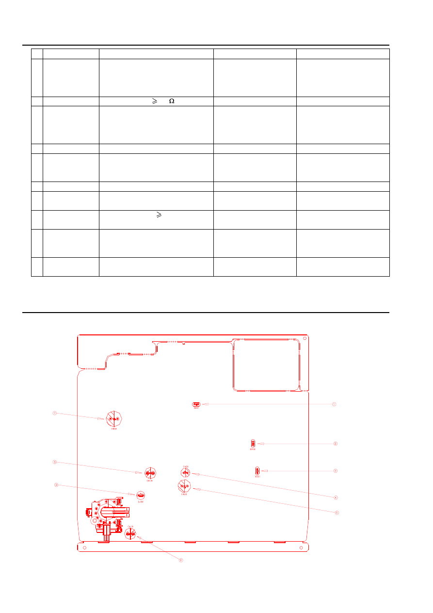
B. Colour Purity, Convergence Adjustment and +B Voltage Check
i. Colour Purity Adjustment (See Fig.6)
BEFORE ANY ADJUSTMENT DESCRIBED BELOW ARE ATTEMPTED, V-HIGH, B+ VOLTAGE AND FOCUSING
ADJUSTMENT MUST BE COMPLETED.
a. Place the TV receiver facing NORTH or SOUTH.
b. Plug in TV receiver and turn it on.
c. Operate the TV receiver over 30 minutes.
d. Fully degauss the TV receiver by using an external degaussing coil.
e. Receive a crosshatch pattern and adjust the static convergence control roughly.
of NN5099K
Low Bright
Standard
x =
288
y =
298
Y =
3.5
x =
± 5
y =
± 5
Y =
± 1
High Bright
Standard
x =
288
y =
298
Y =
160
x =
± 5
y =
± 5
Y =
± 10
AN5195K Initialize:
Color = 63
Cut off R = 31
Tint = 63
Cut off G = 31
S-Bright = 127
Cut off B = 31
U-Bright = 127
Drive R = 63
Contrast = 63
Drive B = 63
Model : UBM
21
f.
Loosen the clamp screw of the deflection yoke and pull the deflection yoke towards you.
g. Enter into ADJUST MENU. Set the values of C-R, C-G, C-B to "00".
h. Adjust the purity magnets until green field is obtained at the center of the screen.
i.
Slowly push the deflection yoke toward cone of CRT and set it where a uniform green field is obtained.
j.
Tighten the clamp screw of the deflection yoke.
k. After COLOUR PURITY ADJUSTMENT, you must adjust the WHITE BALANCE again.
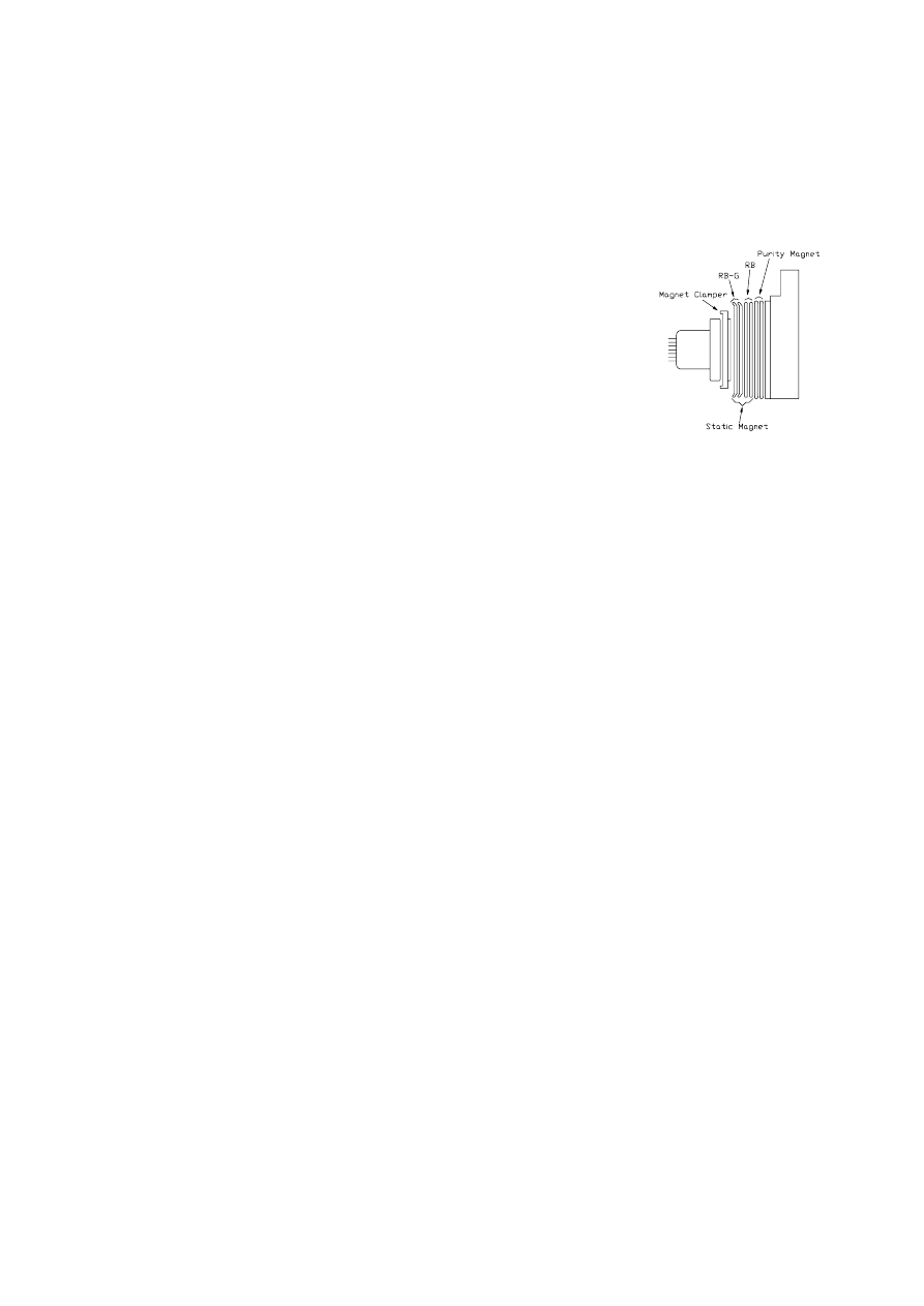
ii. Convergence Adjustment (See Fig.6)
a. Receive a dotted pattern.
b. Unfix the convergence magnet clamper and align red with blue dots
at the center of the screen by rotating (R,B) static convergence magnets.
c. Align Red/Blue with green dots at the center of the screen by rotating
(RB-G) static convergence magnets.
d. Fix the convergence magnets by turning the clamper.
e. Remove the deflection yoke wedges and slightly tilt the deflection yoke
horizontally and vertically to obtain the good overall convergence.
f.
Fix the deflection yoke by wedges.
g. If purity error is found, follow "PURITY ADJUSTMENT".
iii. +B Voltage check
After production aging, it is necessary to check +B voltage.
a. Receive standard colour bar signal.
b. Press key “I.P.C” to select “Natural” mode.
c. Connect digital voltmeter between JP430 (For 21A9BN37) or C403(For other models) and GND. the
read-out on the voltmeter should be +B±1V. if the result is not satisfactory, adjust VR901 to make the
correct voltage to be +B±1V.
(Fig.6)
22
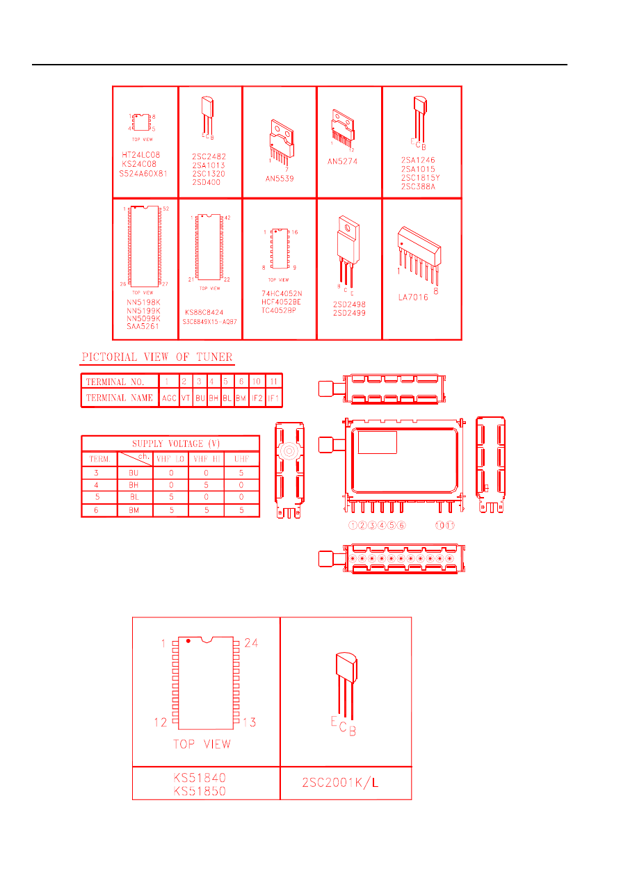
XI. Transistor and IC Identification
A. Main Unit:
B. Remote Control Handset:

23
XII. Schematic Diagram
(Please refer to ****.pdf)
Models
refer to
1401[A315BN87]
-----------
B521-004.pdf

24
XIII. Component Diagrams
i. PCB Main Component Diagram (Top view)/(Bottom view)
(Please refer to ****.pdf)
Models
refer to
1401[A315BN87]
-----------
E3701-980040A1.pdf

25
ii. PCB CRT Component Diagram (Top view)/(Bottom view)
(Please refer to ****.pdf)
Models
refer to
1401[A315BN87]
-----------
E3701-980010B1.pdf and E3701-011030.pdf

26
iii. PCB Handset Component Diagram (Top view)/(Bottom view)
(Please refer to ****.pdf)
Models
refer to
1401[A315BN87]
-----------
E3741-980040.pdf
27
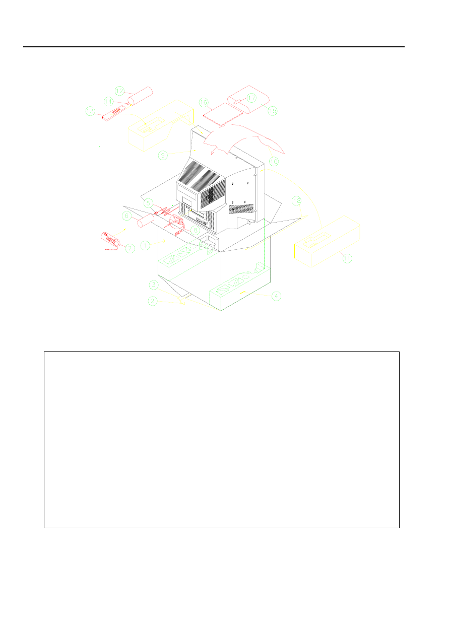
XIV. Packing
No.
Description
Qty.
Action
Remark
1
Gift box
1
Place
Take a giftbox and place it on working table.
2
Nail
8
Nail
3
Masking Tape
Affix
4
Polyfoam End CAP (Bottom)
1
Place
On the bottom of the giftbox.
5
Wire Tie
1
Bind
6
Polybag for AC CORD
1
Take
7
Masking Tape
Affix
8
Cable Tie
1
tie
9
TV Set
1
Put on
Into the giftbox.
10
Expanded Polyethylene Foam Paper
1
Cover
Above the TV set .
11
Polyfoam End CAP (Top)
1
Place
Above the TV set .
12
Polybag for Remote
1
Take
13
Remote Handset ASS’Y
1
Put on
Into the polybag.
14
Masking Tape
Affix
15
Polybag for I/B
1
Take
16
I/B
1
Put on
Into the polybag and put the polybag with
I/B into the giftbox.
17
Masking Tape
Affix
18
Masking Tape
Affix
28
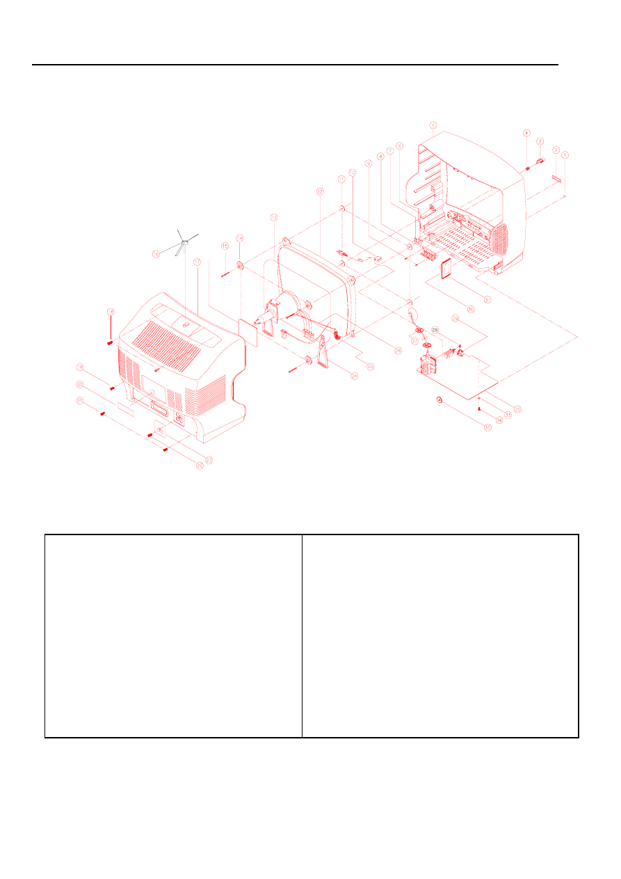
A. TV unit
i. 1401[A315BN87] model
XV. Exploded View Diagram and Parts List
Parts List For Exploded View Diagram
Item
Part No.
Description
QTY.
1
389-
Phone Cover Sheet
1
2
486-
NPM
1
3
279-
Power Knob
1
4
477-
Spring Wire CMP
1
5
200-
Cabinet Front
1
6
269-
Lens SNSR RCN
1
7
269-
Lens LED
1
8
277-
Function Knob
1
9
612-
Self-tapping screw
2
10
254-
AC Line Cord Clip
1
11
376-
Rubber Ring
4
12
102-
14” CRT
1
13
E1115-
Coil Degauss
1
14
639-
Special Washer CRT
4
15
614-
Self-tapping screw
4
17
202-
Cabinet Back
1
18
614-
Self-tapping screw
2
Item
Part No.
Description
QTY.
19
614-
Self-tapping screw
1
20
560-
Model Lable
1
21
614-
Self-tapping screw
2
22
611-
Self-tapping screw
1
23
389-
Cover Plate
1
24
249-
Special Plastic Clip DC
2
25
477-
CRT Spring
1
26
E3421-
Wire Ass’y
1
27
289-
Plastic Ring Protective
2
28
241-
Adaptor for power switch
1
29
250-
Led and sensor holder
1
30
774-
1 Chip Speaker Ass’y
1
31
521-
Felt Paper
2
32
771-
Main PCB Ass’y
1
33
530-
Fire Paper Washer
1
34
612-
Self-tapping screw
1
35
389-
Plate Tuner
1
29
B. Remote handset unit(790-0029XX-XX)
Item
Part No.
Description
Qty.
1
384-
Overlay RCN
1
2
201-
CAB. TP
1
3
263-
Lens FR
1
4
279-
KB
1
5
279-
KB
1
6
279-
KB
1
7
373-
Conductive Rubber
1
8
E3741-
PCB Handset
1
9
203-
CAB. BM
1
10
610-
TS RND2.6X8
2
11
210-
DR BAT
1
12
474-
SPG BAT AA+-
1
13
474-
SPG BAT AA-
1
14
474-
SPG BAT AA+
1
Wyszukiwarka
Podobne podstrony:
Service Manual 1401 21F1 Toshiba
hplj 5p 6p service manual vhnlwmi5rxab6ao6bivsrdhllvztpnnomgxi2ma vhnlwmi5rxab6ao6bivsrdhllvztpnnomg
Oberheim Prommer Service Manual
Korg SQ 10 Service Manual
MAC1500 service manual
Kyocera Universal Feeder UF 1 Service Manual
Proview RA783 LCD Service Manual
indesit witp82euy Service Manual
Glow Worm installation and service manual Hideaway 70CF UIS
Proview PZ456 LCD Service Manual
Glow Worm installation and service manual Ultimate 50CF UIS
ewm2000 service manual
Glow Worm installation and service manual Ultimate 60CF UIS
Proview SH770I LCD Service Manual
M23 Service Manual
Glow Worm installation and service manual Glow micron 60
Konica Minolta QMS 7115, 7118 Service Manual
Honda NSR125 '87 Service Manual
więcej podobnych podstron