
Chapter 4
DC-DC Converter

IFL90 Service Manual
1-1
1. Power
•
cells Li-Ion 18650 size smart battery Pack with 53.28Wh capacity
•
cells Li-Ion 18650 size smart battery Pack with 79.92Wh capacity
2. DC-DC
CONVERTER
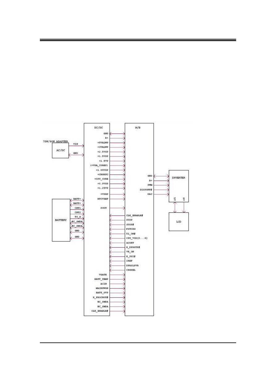
IFL90/91 Series Power System block diagram

IFL90 Service Manual
1-2
2.1 IFL90
Adapter
Description
This specification defines the performance and characteristic of 90W AC adapter
power supply. It supplies a constant voltage 19V output source for IFL90 series
notebook computer.
2.2 Feature
•
Accepts universal input from 90V AC to 264V AC
•
Offers constant Voltage 19V output source with 90W max output power capacity.
•
High efficiency 85%
min at 100Vac
•
Compact Size
2.3 Adapter
Electrical
Specification
•
Input Voltage range: universal input, 90VAC TO 264VAC
•
Inrush current: 150A Peak and no damage @220Vac
•
Input frequency range: 47~63Hz
•
Input Current: 2.0Amax at 100 VAC
•
Start-up time: 3sec Max. @115Vac
•
HOLD-UP time: 10ms min. @115VAC, full load condition
•
OVP: 29V max. automatic shut down
•
Short circuit protection: Output can be shorted without damage, and auto recovery.
•
OUTPUT Voltage Regulation: 18.5-20V including the effects of line Voltage variation, load
current, ripple and noise
•
OUTPUT Current: Current: 0Amin, 4.74Amax continuous
•
OUTPUT Voltage ripple: 380mv PK-PK for full load.
•
OUTPUT Voltage Dynamic regulation: Output voltage within 18.5-19.9V, load current
10%
←→100%, frequency 100Hz, 50% duty cycle, recover time≤1msec.
•
DC OUTPUT PIN OUT:
PIN1 Center
Pin
Adapter
+output
PIN2 Barrel
(Ring)
Adapter
returns
.
•
Temperature Range:
Operating temperature:
0 *C TO 40 *C
Storage temperature:
-20 *C TO 65 *C

IFL90 Service Manual
1-3
2.4 IFL91
Adapter
Description
This specification defines the performance and characteristic of 75W AC adapter
power supply. It supplies a constant voltage 19V output source for IFL91series
notebook computer.
2.5 Feature
•
Accepts universal input from 100V AC to 264V AC
•
Offers constant Voltage 19V output source
•
High efficiency 85%
min at 115Vac,full load
•
Compact Size
2.6 Electrical
Specification
•
Input Voltage range:universal input, 100VAC TO 264AC
•
Inrush current: 220A max peak at 240Vac and No damage
•
Input frequency range: 47~63Hz
•
Input Current: 1.7Amax at 100VAC
•
Start-up time: 5sec Max. @115 and 230 Vac,full load
•
HOLD-UP time: >5ms@115VAC, full load condition
•
OVP: 29V max. automatic shut down
•
Short circuit protection: Output can be shorted without damage, and auto recovery
•
OUTPUT Voltage Regulation: 18.5-20V including the effects of line Voltage variation, load
current, ripple and noise.
•
OUTPUT Current: 0Amin, 3.95Amax continuous
•
OUTPUT Voltage ripple: 380mv PK-PK for resistor load
•
OUTPUT Voltage Dynamic regulation: Output voltage within18.5-20V, load current
10%
←→100%, frequency 100Hz, 50% duty cycle, recover time≤1msec.
•
DC OUTPUT PIN OUT:
PIN1 Center
Pin
Adapter
+output
PIN2 Barrel
(Ring)
Adapter
returns.
•
1.3.1Temperature Range:
Operating temperature:
0 *C TO 40 *C
Storage temperature: -20 *C TO 65 *C

IFL90 Service Manual
1-4
3. DC-DC
CONVERTER
3.1 Description
The DC-DC converter is designed to supply the power for IFL90/91 series
notebook computer of Compal. It supply +5VALWP, +3VALWP, +1.8VP,
+1.5VSP, +1.25VP, +1.05VSP, +2.5VSP, +0.9VSP,+VGA_COREP, for logical
system, + CPU_CORE for CPU and supplies for the built-in KB925
microprocessor which handles the keyboard and PMU control functions of the
system. The power ON/OFF is controlled by KB925. There is also a built-in
charger power source. It can charge battery pack whether the computer is ON or
OFF.
3.2 Features
•
High efficiency, up to 85% (using battery)
•
Accept wide range DC input voltage from 8V to 19V
•
Built-in charger power source
•
The power ON/OFF is controlled by software
3.3 Electrical
specification
Input Voltage/Current
•
8V to19V at the summing point of AC-DC and battery
•
INPUT Current 10.8A max from 9-cell battery
INPUT Current 9.6A max from 6-cell battery
•
4.74A max from 90W AC-DC Adapter.
3.95A max from 75W AC-DC Adapter.
3.4 Temperature
Range:
•
Operating temperature : 0* C to 40* C
•
storage temperature range : -20* C to 65* CDC/DC OUTPUT
•
Fixed output voltage/Current

IFL90 Service Manual
1-5
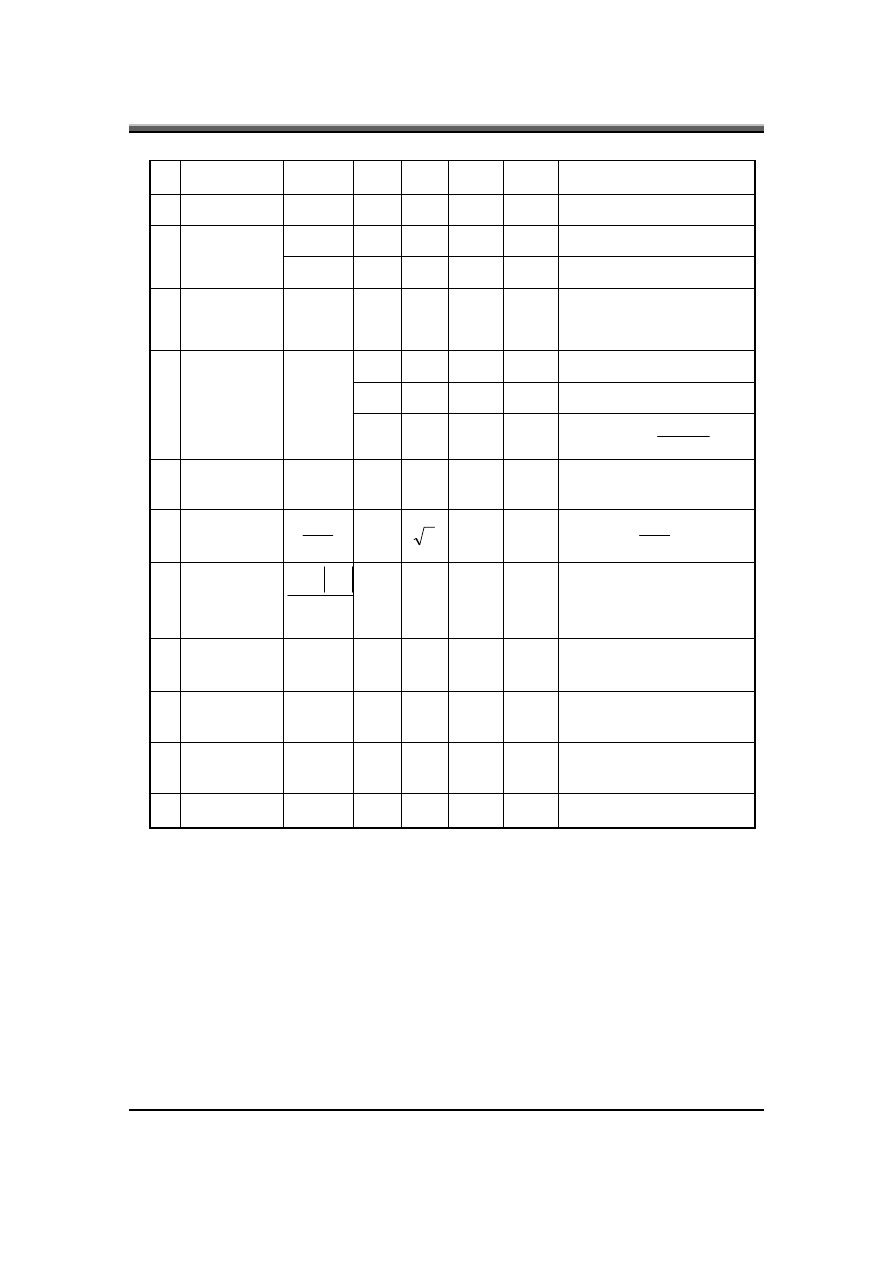
Item +5VALWP
+CPU_CORE
+VGA_COREP
nominal voltage
+5V
depend on VID 1.1V
min. current
0A
0A 0A
max. current
5A
36A
16A
peak current
6A
44A
17.9A
total regulation
5V±5%
depend on VCC static and 1.1V±5%
Transient
Tolerance--
ripple voltage
100mVp-p max
20mVp-p max@36A 60mVp-p max
Item +0.9VSP
+3VALWP +1.05VSP
nominal voltage
+0.9V
+3.3V
+1.5V
min. current
0A
0A
0A
max. current
2A
5A
5A
peak current
3A
6A
6A
total regulation
0.9V±5%
3.3V±5%
1.5V±5%
ripple voltage
40mVp-p max
100mVp-p max
60mVp-p max.
Item
+1.8VP +1.5VSP +1.25VSP
nominal voltage
+1.8V +1.5V +1.25V
min. current
0A 0A 0A
max. current
5A 5A 350mA
peak current
6A 6A 3A
total regulation
1.8V±5% 1.5V±5% 1.25V±5%
ripple voltage 60mVp-p max 100mVp-p max 100mVp-p max

IFL90 Service Manual
1-6
•
VOLTAGE IDENTIFICATION CODES
VID6 VID5 VID4 VID3 VID2 VID1 VID0 VDAC
0 0 0 0 0 0 0
1.5000
0 0 0 0 0 0 1
1.4875
0 0 0 0 0 1 0
1.4750
0 0 0 0 0 1 1
1.4625
0 0 0 0 1 0 0
1.4500
0 0 0 0 1 0 1
1.4375
0 0 0 0 1 1 0
1.4250
0 0 0 0 1 1 1
1.4125
0 0 0 1 0 0 0
1.4000
0 0 0 1 0 0 1
1.3875
0 0 0 1 0 1 0
1.3750
0 0 0 1 0 1 1
1.3625
0 0 0 1 1 0 0
1.3500
0 0 0 1 1 0 1
1.3375
0 0 0 1 1 1 0
1.3250
0 0 0 1 1 1 1
1.3125
0 0 1 0 0 0 0
1.3000
0 0 1 0 0 0 1
1.2875
0 0 1 0 0 1 0
1.2750
0 0 1 0 0 1 1
1.2625
0 0 1 0 1 0 0
1.2500
0 0 1 0 1 0 1
1.2375
0 0 1 0 1 1 0
1.2250
0 0 1 0 1 1 1
1.2125
0 0 1 1 0 0 0
1.2000
0 0 1 1 0 0 1
1.1875
0 0 1 1 0 1 0
1.1750
0 0 1 1 0 1 1
1.1625
0 0 1 1 1 0 0
1.1500
0 0 1 1 1 0 1
1.1375
0 0 1 1 1 1 0
1.1250
0 0 1 1 1 1 1
1.1125
0 1 0 0 0 0 0
1.1000
0 1 0 0 0 0 1
1.0875
1 0 0 0 1 0
1.164V

IFL90 Service Manual
1-7
0 1 0 0 0 1 0
1.0750
0 1 0 0 0 1 1
1.0625
0 1 0 0 1 0 0
1.0500
0 1 0 0 1 0 1
1.0375
0 1 0 0 1 1 0
1.0250
0 1 0 0 1 1 1
1.0125
0 1 0 1 0 0 0
1.0000
0 1 0 1 0 0 1
0.9875
0 1 0 1 0 1 0
0.9750
0 1 0 1 0 1 1
0.9625
0 1 0 1 1 0 0
0.9500
0 1 0 1 1 0 1
0.9375
0 1 0 1 1 1 0
0.9250
0 1 0 1 1 1 1
0.9125
0 1 1 0 0 0 0
0.9000
0 1 1 0 0 0 1
0.8875
0 1 1 0 0 1 0
0.8750
0 1 1 0 0 1 1
0.8625
0 1 1 0 1 0 0
0.8500
0 1 1 0 1 0 1
0.8375
0 1 1 0 1 1 0
0.8250
0 1 1 0 1 1 1
0.8125
0 1 1 1 0 0 0
0.8000
0 1 1 1 0 0 1
0.7875
0 1 1 1 0 1 0
0.7750
0 1 1 1 0 1 1
0.7625
0 1 1 1 1 0 0
0.7500
0 1 1 1 1 0 1
0.7375
0 1 1 1 1 1 0
0.7250
0 1 1 1 1 1 1
0.7125
1 0 0 0 0 0 0
0.7000
1 0 0 0 0 0 1
0.6875
1 0 0 0 0 1 0
0.6750
1 0 0 0 0 1 1
0.6650
1 0 0 0 1 0 0
0.6500
1 0 0 0 1 0 1
0.6375
1 0 0 0 1 1 0
0.6250

IFL90 Service Manual
1-8
1 0 0 0 1 1 1
0.6125
1 0 0 1 0 0 0
0.6000
1 0 0 1 0 0 1
0.5875
1 0 0 1 0 1
0.5750
1 0 0 1 0 1 1
0.5625
1 0 0 1 1 0 0
0.5500
1 0 0 1 1 0 1
0.5375
1
1
0 0 1 1 1 0
0.5250
1 0 0 1 1 1 1
0.5125
1 0 1 0 0 0 0
0.5000
1 0 1 0 0 0 1
0.4875
1 0 1 0 0 1 0
0.4750
1 0 1 0 0 1 1
0.4625
1 0 1 0 1 0 0
0.4500
1 0 1 0 1 0 1
0.4375
1 0 1 0 1 1 0
0.4250
1 0 1 0 1 1 1
0.4125
1 0 1 1 0 0 0
0.4000
1 0 1 1 0 0 1
0.3875
1 0 1 1 0 1 0
0.3750
1 0 1 1 0 1 1
0.3625
1 0 1 1 1 0 0
0.3500
1 0 1 1 1 0 1
0.3375
1 0 1 1 1 1 0
0.3250
1 0 1 1 1 1 1
0.3125
1 1 0 0 0 0 0
0.3000
1 1 0 0 0 0 1
0.2875
1 1 0 0 0 1 0
0.2750
1 1 0 0 0 1 1
0.2625
1 1 0 0 1 0 0
0.2500
1 1 0 0 1 0 1
0.2375
1
1
1 0 0 1 1 0
0.2250
1 1 0 0 1 1 1
0.2125
1 1 0 1 0 0 0
0.2000
1
1
1 0 1 0 0 1
0.1875
1 1 0 1 0 1 0
0.1750
1
1
1 0 1 0 1 1
0.1625

IFL90 Service Manual
1-9
1
11
1 0 1 1 0 0
0.1500
1 1 0 1 1 0 1
0.1375
1 1 0 1 1 1 0
0.1250
1 1 0 1 1 1 1
0.1125
1 1 1 0 0 0 0
0.1000
1 1 1 0 0 0 1
0.8750
1 1 1 0 0 1 0
0.7500
1 1 1 0 0 1 1
0.6250
1 1 1 0 1 0 0
0.5000
1 1 1 0 1 0 1
0.3750
1 1 1 0 1 1 0
0.2500
1 1 1 0 1 1 1
0.1250
1 1 1 1 0 0 0 0
1 1 1 1 0 0 1 0
1 1 1 1 0 1 0 0
1 1 1 1 0 1 1 0
1 1 1 1 1 0 0 0
1 1 1 1 1 0 1 0
1 1 1 1 1 1 0 0
1 1 1 1 1 1 1 0
3.5 Charger
•
Controlled by KB925 microprocessor from motherboard
•
Temperature sense capability for the battery (charge active between 0*C~ 40*C)
•
Fast charge current 3Amps(max.) for Li-Ion Battery at system off, approach 25W fast charge
at system ON. (depend on system load)
•
Trickle charge: Typical 600mA pre-charge current for Li-Ion Battery . All trickle charge are
controlled by KB925.
•
Charge termination: When Fully-Charge bit is set ,charger is terminated by KB925
•
When system is turned off , the charge time is 4.0 hrs typically from empty to full for Li-Ion
9 cell battery .When system is turned off, the charge time is 3.0 hrs typically from empty to
full for Li-Ion6 cell battery .
•
Other battery services are presented by KB925 microprocessor includes maximum charging
timer, charging temperature range etc.

IFL90 Service Manual
1-10
•
Charger power:
Constant current mode: 3.0A±8%
Constant adapter current mode: 4.263A±6% (For 90W system)
Constant adapter current mode: 3.079A±6% (For 75W system)
BATT+ Constant Voltage mode: 12.6V±1% for Li-Ion Battery.
3.6 OVER Current protection:
•
+3VALWP: >6.66A.
•
+5VALWP: >6.66A.
•
CPU_CORE: >48A.
•
+1.8VP: >6A.
•
+1.5VSP: >6A.
•
+1.05VSP: >6A
•
1.25VP:>6A
3.7 OVER
Voltage
protection:
•
+5VALWP: 5V +(8% ~ 14%)
•
+3VALWP: 3.3V +(8% ~ 14%)
•
+CPU_CORE
over 300mV of programmed VID level
•
+1.8VP value+125mV
•
+1.5VSP value+125mV
•
+1.05VSP value+125mV
•
+1.25VP value+125mV
3.8 Under
voltage
protection
•
+5VALWP: 5V *(65% ~ 75%)
•
+3VALWP: 3.3V *(65% ~75%)
•
+CPU_CORE
under 400mV of programmed VID level
•
+1.8VP value-133mV
•
+1.5VSP value-133mV
•
+1.05VSP value-133mV
•
+1.25VP value-133mV
IFL90 Service Manual
1-11
3.9 Short circuit protection:
•
Latch mode for +5VALWP, +3VALWP,+CPU_CORE
3.10 I/O
3.10.1 DC-Jack
Pin 1,2: Center pin Adapter power +input
Pin 3,4: Barrel (Ring) Adapter power return
3.10.2 Battery Connector
Pin 1: BATT+
Pin 2: BATT+
Pin 3: ID(CNT1)
Pin 4: B/I(CNT2)
Pin 5: SMC(EC_SMCA)
Pin 6: SMD(EC_SMDA)
Pin 7: TS(TS_A)
Pin 8: GND
Pin 9: GND
3.10.3 Interface between Power with M/B
DC/DC
Signals I/O
Voltage
Level
Description
SUSP#
I 0~3.3V
Low Active, system suspend control signal
51ON#
I 0~floating
Low Active, POWER ON control signal.
FSTCHG
I 0~3.3V
High Active, ENE925 use this pin to control the fast charge of charge
ACOFF
I 0~3.3V
High Active, turn off the Adaptor power for battery automatic learning cycle
ACIN
O 0~3.3V
High Active, provide to ENE925 to mean the Adaptor power is present
VGATE
O 0~3.3V
High Active, it will go high when +CPU_CORE is ready
VR_ON
I 0~3.3V
High Active, turn on/off the +CPU_COREP & VID_VCC
BATT_TEMP
O 0~3.3V
Analog signal, ENE925 using this voltage level to calculate battery’s
temperature
IREF
I 0~3.3V
Analog signal, ENE925 using this voltage for setting charge current
IFL90 Service Manual
1-12
VID [0..6]
I 0~3.3V
The +CPU_CORE voltage depends on those PIN’s VID[6..0]
CHGRTC
O 3.3V
Charge RTC-battery power source
EC_SMDA,
EC_SMCA
I/O 0~5V
Interface of Smbus, communicate between ENE925 and smart battery
SYSON
I 0~3.3V
High Active, ENE925 use this pin to control the SYSON signal
BATT_AOVP O
0~3.3V
Analog signal, ENE925 using this voltage level for battery over voltage
protection
PSI#
I 0~1.05V
Analog signal, enable CPU_CORE regulator at light load mode.
DPRSLPVR
I 0~1.05V
Analog signal, control CPU C3,C4 signal.
H_DPRSTP#
I 0~1.05V
Analog signal, control CPU C3,C4 signal.
CLK_ENABLE# O 0~3.3V
Analog signal, clock generator enable signal.
CHGSEL
I 0~3.3V
Control 2800mAH charge voltage
3.11 BATTERY
3.11.1 Li-Ion smart
•
18650 size, 3S2P, 12.6V/4800mAH
•
More than 300 charging/discharging cycles for Li-ion battery.
•
Modularized battery pack, easy to be replaced.
3.11.2 On board RTC battery:
•
Maxell ML1220T13 3V/14mAH Lithium
•
Sanyo ML1220T28 3V/15mAH Lithium
•
Panasonic ML1220/B 3V/17mAH Lithium
CAUTION
Danger of explosion if battery is incorrectly replaced.
Replace only with the same or equivalent type recommended by the manufacturer.
Dispose of used batteries according to the manufacturer’s instructions.
IFL90 Service Manual
1-13
4. INVERTER
SPECIFICATION
IFL90/91 15.4 inch inverter spec
Description
This inverter is designed to light up the CCFL of LCD for IFL90/91notebook.
This inverter is designed to light up the CCFL of LCD for notebook. It should be
supported IFL90/91 15.4 LCD panels. There are two control signals that come
from system to control lamp brightness. One signal is named DAC_BRIG, which
limits current to meet LCD lamp current specification. Another one is named
PWM, which adjusts lamp brightness. This inverter brightness is adjusted by
PWM burst mode. The PWM burst mode is that turning on and off the lamp at a
rate of 150Hz. The effective brightness is a function of the duty cycle.
4.1 Features
•
Wide range 9V to 21V input voltage
•
Brightness adjustment by PWM burst mode.
•
Close loop controls lamp current.
4.2 Absolute maximum rating
•
Environment: Temperature:
Operating temperature: 0℃ ~ 55℃
Storage temperature : -20℃ ~ 70℃
Humidity: 0 ~ 90% without condensation
MTBF: MIN 50000 hours.(In Compal system)
4.3 Electrical
characteristic
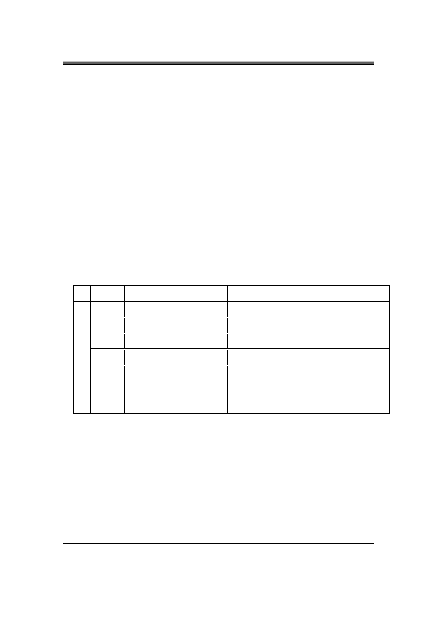
No Item Symbol
Min.
Typ.
Max.
Unit
Comment
1 Input
voltage INV_PWR 9
14.8
21 V
7.5V(continuous) can work
*Note 1
2 Input
current
Iin
--
0.33
-- A
3 Lamp
current
IL
3.0
--
6.8 mA DAC=0V *Note 2
4 Lamp
current
IL
2.7
--
6.3 mA
DAC=1V
4 Frequency
F
45 55 65 KHz
*Note3
5 Output
power
Pout
--
--
4.5
W
6 Efficiency
η
80%
-- -- --
IFL90 Service Manual
1-14
7
Starting
voltage
V
s
1600
-- -- V
At
0’C
8 Starting
time
Tvs
1
--
1.5 Sec
2.8
3.3
3.6
V Backlight
on/off
signal
9 Dispoff#
0
0.5
0.8
V
Low
level
10
Limited lamp
maximum
current
DAC-
BRIG
0 3.3 V
*Note
2
142
150
158 Hz PWM
signal
frequency
3.0
3.3
3.6
V
PWM signal amplitude
11
PWM signal
*note 4
INV_PW
M
30 -- 100 %
Period
Ton
Duty
=
12
lamp current
over-shoot
PK
Zero
I
−
-- -- 10 %
Line transient( 10.8V to
21V/100us) and turn on
transient
13
Current
Waveform
factor
rms
p
I
I
1.27
2
1.56 Multiple
OR
rms
p
I
I
−
*10
14
Unbalance
Rate
rms
p
p
I
I
I
−
−
-10%
0 +10% Multiple
15
Turn off
current
(Hight side)
IHL -- -- 0 A
PWM=30%
15
Turn off
voltage
(Low side)
Voff -- --
150Vp-
p
V PWM=30%
16
Voltage Rise
time (Low
side)
Trise -- --
300us
us
PWM=30%
17
Voltage fall
time(Low side)
Tfall -- --
300us
us
PWM=30%
Notes:
•
The inverter can work in 7.5V input voltae(continuous),but 7.5V electronic characteristic will
not be care.(Note:the display must be normal and can not glitter or become dark)
•
Limited lamp maximum current by DAC_BRIG signal:
When DAC_BRIG voltage is 0V and INV_PWM enables (100%), lamp has max. limited current.
When DAC_BRIG voltage is 3.3V and INV_PWM enables (100%), lamp has min. limited current.
When add 1V DAC, the 100% Lamp current will decrease 0.5mA.
DAC_BRIG signal comes from system chipset with internal resistance of 3KΩ.
IFL90 Service Manual
1-15
•
Inverter operating frequency should be within specification (45~65kHz) at max. and min.
brightness load.
•
INV_PWM enable implies INV_PWM signal is High level (On duty cycle is 100%). It is a
square wave of 150Hz to adjust backlight brightness that is a function of PWM duty cycle.
Backlight brightness is maximum value under INV_PWM at 100% and brightness is
minimum under INV_PWM at 30%.
•
The system interface signals belong to 3.3V.
•
Please make sure open lamp output voltage should be within starting voltage specification.
•
Inverter should pass human body safety test.
•
Inverter should no smoking by any component open/ short test
•
Transformer voltage stress should not be over 85% under any condition (turn on overshoot
transient and line transient).
•
Audio noise should be less than 36dB at 10 cm distance.
4.4 Electrical
specification
4.4.1 Electrical
specification
No Symbol
Min.
Typ.
Max.
Unit
Comment
V
oper
. -- 650 -- Vrms
Lamp
operating
voltage(650+/-50)
I
L
6.2
6.5
6.8
mArms
DAC_BRIG: 0 V, PWM: 100%
I
L
3.0
3.3
3.6
mArms
DAC_BRIG: 0 V, PWM:30%
I
L
5.7
6
6.3
mArms
DAC_BRIG: 1 V, PWM: 100%
I
L
2.7
3
3.3
mArms
DAC_BRIG: 1 V, PWM:30%
f 45 55 65 KHz
1
η
80% -- --
--
4.4.2 Thermal
All components on inverter board should follow below rules:
•
Component using conditions (component stress) must be within component specification
including voltage rating, current rating, temperature etc.
•
Component temperature should follow below:
Δ
T < 30℃ , at 25 , 35℃.
Component temperature should be less than 70℃ inside system at 35℃.
IFL90 Service Manual
1-16
4.5 Connector
description
4.5.1 Input
Connector:
CN1: ACES 87213-0700; JST SM07B-SRSS-TB
Pin No.
Symbol
Description
1
INV_PWR
Input voltage (9V-21V)
2
INV_PWR
Input voltage (9V-21V)
3
INV_PWM
Adjust brightness by burst mode(3.3 V 150Hz)
4
DISOFF #
Backlight on/off control, active HIGH(3.3V)
5
DAC_BRIG
Max. current limit
6
GND
Power system return
7
GND
Power system return
4.5.2 Output
Connector:
CN2: JST_SM02B_BHSS-1
Pin No.
Symbol
Description
1
HV
Connected to high voltage of LCD lamp
2
LV
Connected to low voltage of LCD lamp
Note : Please mark “ CAUTION HIGH VOLTAGE” around CN2
4.6 Safety
Protection
4.6.1 Open
lamp
protection:
When inverter is on open lamp status, any component on inverter should be O.K
and inverter is no damaged, no fire and no arcing. If inverter can’t shunt down
during open lamp happen, inverter must pass below conditions:
•
Human body test.
•
Open lamp burning: Inverter burns for 24 hours at open lamp status. No parts damage.

IFL90 Service Manual
1-17
4.6.2 Human body safety test:
Short inverter output, transformer secondary output to GND by a 2KΩ resistor
which connects one end to GND and another one to those outputs. They should
meet output current limitation requirement as follow. Output current I is the
current that flows through 2KΩ resistor.
•
Output current I ≦ 0.7mA , if frequency f ≦ 1KHz
•
Output current I ≦ 0.7mA * f (kHz) , if f ≧ 1KHz.
However, output current should be less than 70mA even frequency is more than
100KHz.
4.6.3 Abnormal
test:
Any one component is short or open; inverter should be no fire, no arcing. And
result must meet output current limitation requirement.
Wyszukiwarka
Podobne podstrony:
DC DC Converters k99e25 l1120
Inverter DC DC Converter Inductorless
DC DC Converter for EWB Wind Turbine Project review
IFL90 ch6 Testing and Troubleshooting intel
Kigo DVD Converter Intel SN
IFL90 ch1 System description spec intel
Boost Converter DC DC Boost PPT
Development Of High Frequency Link Direct Dc To Ac Converters For Link Direct Dc To Ac Converters Fo
inverter 2002 chapter 4 DC to AC conversion inverter tutorial
M Dąbrowska Kobieta piękną jest
drzwi czech e60 EASY 719 DC RC
2006 03 Sterowanie PWM silnikami DC większej mocy
stale, Elektrotechnika, dc pobierane, Podstawy Nauk o materialach, Przydatne, Sprawka
06, Szkoła, Politechnika 1- 5 sem, chomikuj, 4 sem (graviora), dc word (graviora)
dc dc stepup, Schematic Prints
Przetwornica DC DC (AVT1507)
Przeksztaltniki DC DC Prezentacja Kawy
więcej podobnych podstron