
SysVar 08.02.03 en
1 of 170
SOFTWARE
KR C...
System Variables
KUKA System Software (KSS)
Issued: 05 Jul 2005
Version: 03

2 of 170
SysVar 08.02.03 en
e
Copyright
KUKA Roboter GmbH
This documentation or excerpts therefrom may not be reproduced or disclosed to third parties without the express permission of the publishers.
Other functions not described in this documentation may be operable in the controller. The user has no claim to these functions, however, in
the case of a replacement or service work.
We have checked the content of this documentation for conformity with the hardware and software described. Nevertheless, discrepancies
cannot be precluded, for which reason we are not able to guarantee total conformity. The information in this documentation is checked on a
regular basis, however, and necessary corrections will be incorporated in subsequent editions.
Subject to technical alterations without an effect on the function.

3 of 170
SysVar 08.02.03 en
Contents
1
How to use this documentation
5
. . . . . . . . . . . . . . . . . . . . . . . . . . . . . . . . . . .
2
A
7
. . . . . . . . . . . . . . . . . . . . . . . . . . . . . . . . . . . . . . . . . . . . . . . . . . . . . . . . . . . . . . .
3
B
29
. . . . . . . . . . . . . . . . . . . . . . . . . . . . . . . . . . . . . . . . . . . . . . . . . . . . . . . . . . . . . . .
4
C
34
. . . . . . . . . . . . . . . . . . . . . . . . . . . . . . . . . . . . . . . . . . . . . . . . . . . . . . . . . . . . . . .
5
D
41
. . . . . . . . . . . . . . . . . . . . . . . . . . . . . . . . . . . . . . . . . . . . . . . . . . . . . . . . . . . . . . .
6
E
53
. . . . . . . . . . . . . . . . . . . . . . . . . . . . . . . . . . . . . . . . . . . . . . . . . . . . . . . . . . . . . . . .
7
F
63
. . . . . . . . . . . . . . . . . . . . . . . . . . . . . . . . . . . . . . . . . . . . . . . . . . . . . . . . . . . . . . . .
8
G
66
. . . . . . . . . . . . . . . . . . . . . . . . . . . . . . . . . . . . . . . . . . . . . . . . . . . . . . . . . . . . . . .
9
H
68
. . . . . . . . . . . . . . . . . . . . . . . . . . . . . . . . . . . . . . . . . . . . . . . . . . . . . . . . . . . . . . .
10
I
70
. . . . . . . . . . . . . . . . . . . . . . . . . . . . . . . . . . . . . . . . . . . . . . . . . . . . . . . . . . . . . . . .
11
J
77
. . . . . . . . . . . . . . . . . . . . . . . . . . . . . . . . . . . . . . . . . . . . . . . . . . . . . . . . . . . . . . . .
12
K
78
. . . . . . . . . . . . . . . . . . . . . . . . . . . . . . . . . . . . . . . . . . . . . . . . . . . . . . . . . . . . . . .
13
L
81
. . . . . . . . . . . . . . . . . . . . . . . . . . . . . . . . . . . . . . . . . . . . . . . . . . . . . . . . . . . . . . . .
14
M
85
. . . . . . . . . . . . . . . . . . . . . . . . . . . . . . . . . . . . . . . . . . . . . . . . . . . . . . . . . . . . . . .
15
N
92
. . . . . . . . . . . . . . . . . . . . . . . . . . . . . . . . . . . . . . . . . . . . . . . . . . . . . . . . . . . . . . .
16
O
95
. . . . . . . . . . . . . . . . . . . . . . . . . . . . . . . . . . . . . . . . . . . . . . . . . . . . . . . . . . . . . . .
17
P
100
. . . . . . . . . . . . . . . . . . . . . . . . . . . . . . . . . . . . . . . . . . . . . . . . . . . . . . . . . . . . . . . .
18
R
115
. . . . . . . . . . . . . . . . . . . . . . . . . . . . . . . . . . . . . . . . . . . . . . . . . . . . . . . . . . . . . . .
19
S
124
. . . . . . . . . . . . . . . . . . . . . . . . . . . . . . . . . . . . . . . . . . . . . . . . . . . . . . . . . . . . . . . .
20
T
139
. . . . . . . . . . . . . . . . . . . . . . . . . . . . . . . . . . . . . . . . . . . . . . . . . . . . . . . . . . . . . . . .
21
U
158
. . . . . . . . . . . . . . . . . . . . . . . . . . . . . . . . . . . . . . . . . . . . . . . . . . . . . . . . . . . . . . .
22
V
159
. . . . . . . . . . . . . . . . . . . . . . . . . . . . . . . . . . . . . . . . . . . . . . . . . . . . . . . . . . . . . . . .
23
W
166
. . . . . . . . . . . . . . . . . . . . . . . . . . . . . . . . . . . . . . . . . . . . . . . . . . . . . . . . . . . . . . .
24
Z
170
. . . . . . . . . . . . . . . . . . . . . . . . . . . . . . . . . . . . . . . . . . . . . . . . . . . . . . . . . . . . . . . .

System Variables
4 of 170
SysVar 08.02.03 en
1
How to use this documentation
5 of 170
SysVar 08.02.03 en
1
How to use this documentation
This tabular summary of the system variables is intended to serve as an aid for programmers
with good knowledge of the functions of the KUKA robot system and the KR C... controller,
and who are thoroughly familiar with programming.
Many variable values are preset by the manufacturer (default values) and should not be
changed without a compelling reason. If changes are nevertheless necessary, they can be
carried out using the variable modification function or by editing the files.
Change the values of variables only if you have sufficient knowledge of the func-
tions of the system variables and their effects!
The manufacturer accepts no liability and provides no warranty whatsoever
for damage of any kind arising from improper modification of variable
values or their modification for a purpose other than the intended one.
Please also observe the chapter [Safety] in the handbook.
Please note:
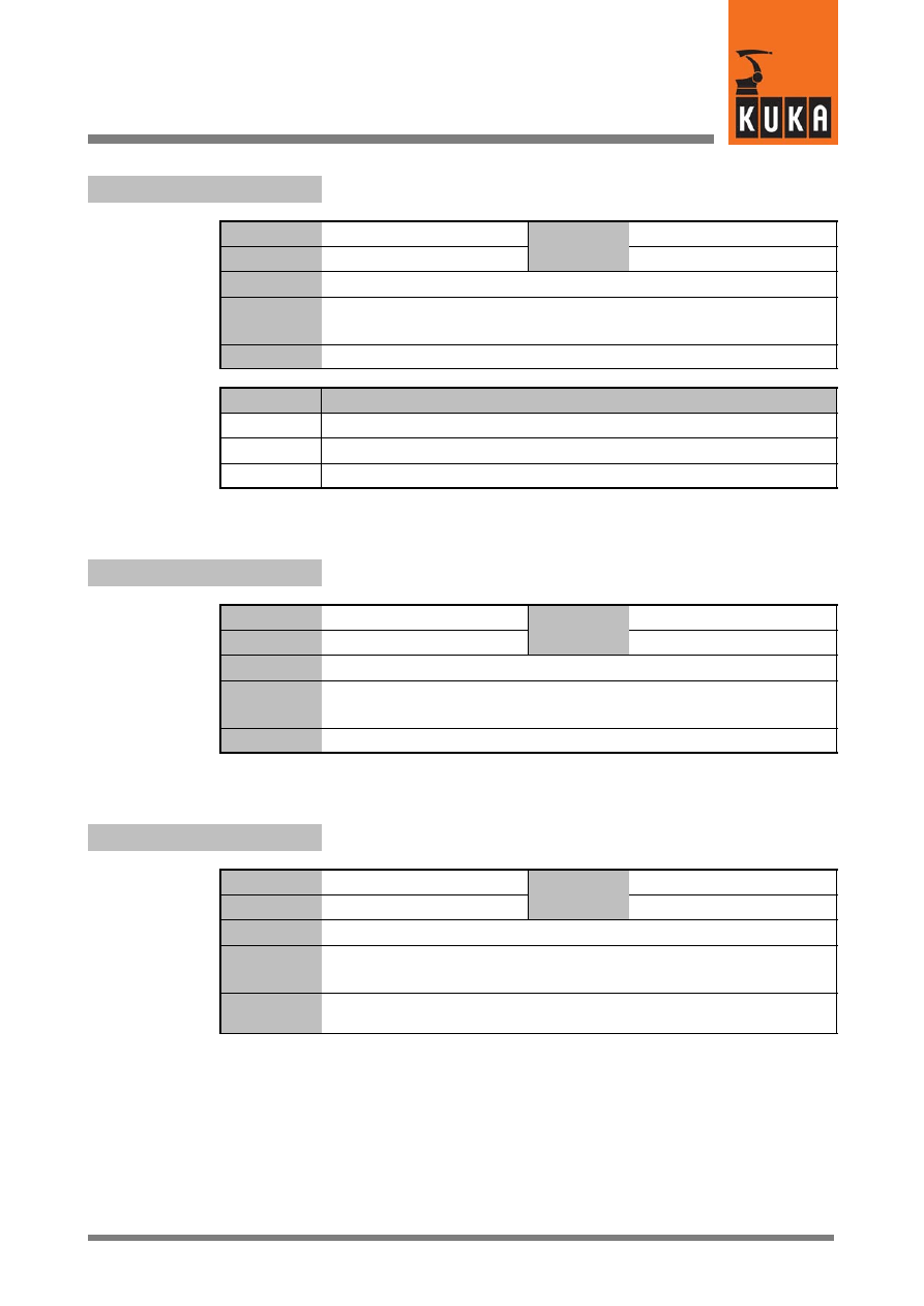
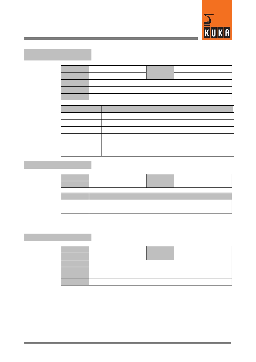
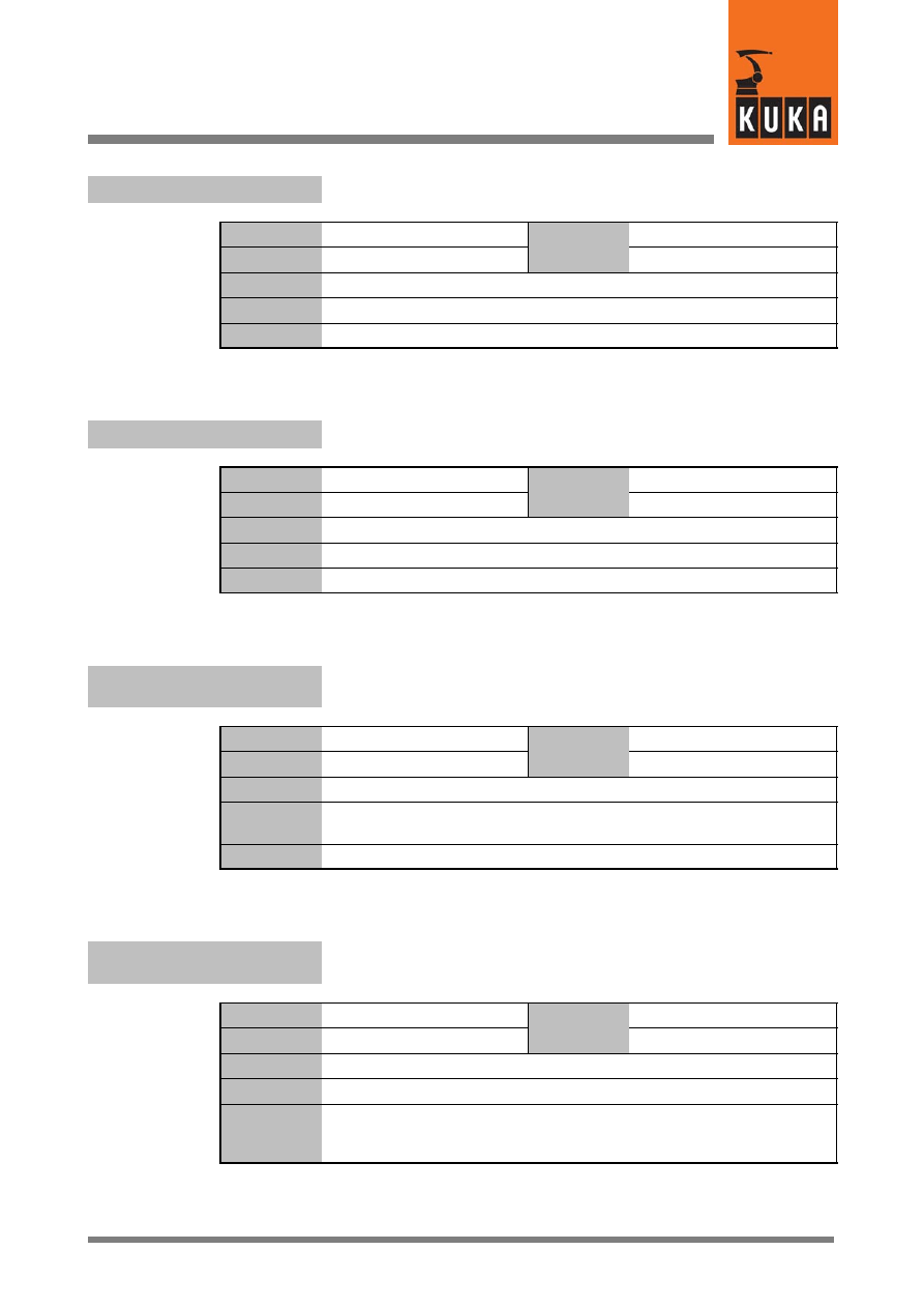
Each table is preceded by a title with the name and function of the system variable, e.g.:
Variable name
Function of the variable
Data type
Value
min.
Unit
Value
max.
In file
Original line
Comments
Options
Effect
If no Options are specified, then the second table is omitted.
System Variables
6 of 170
SysVar 08.02.03 en
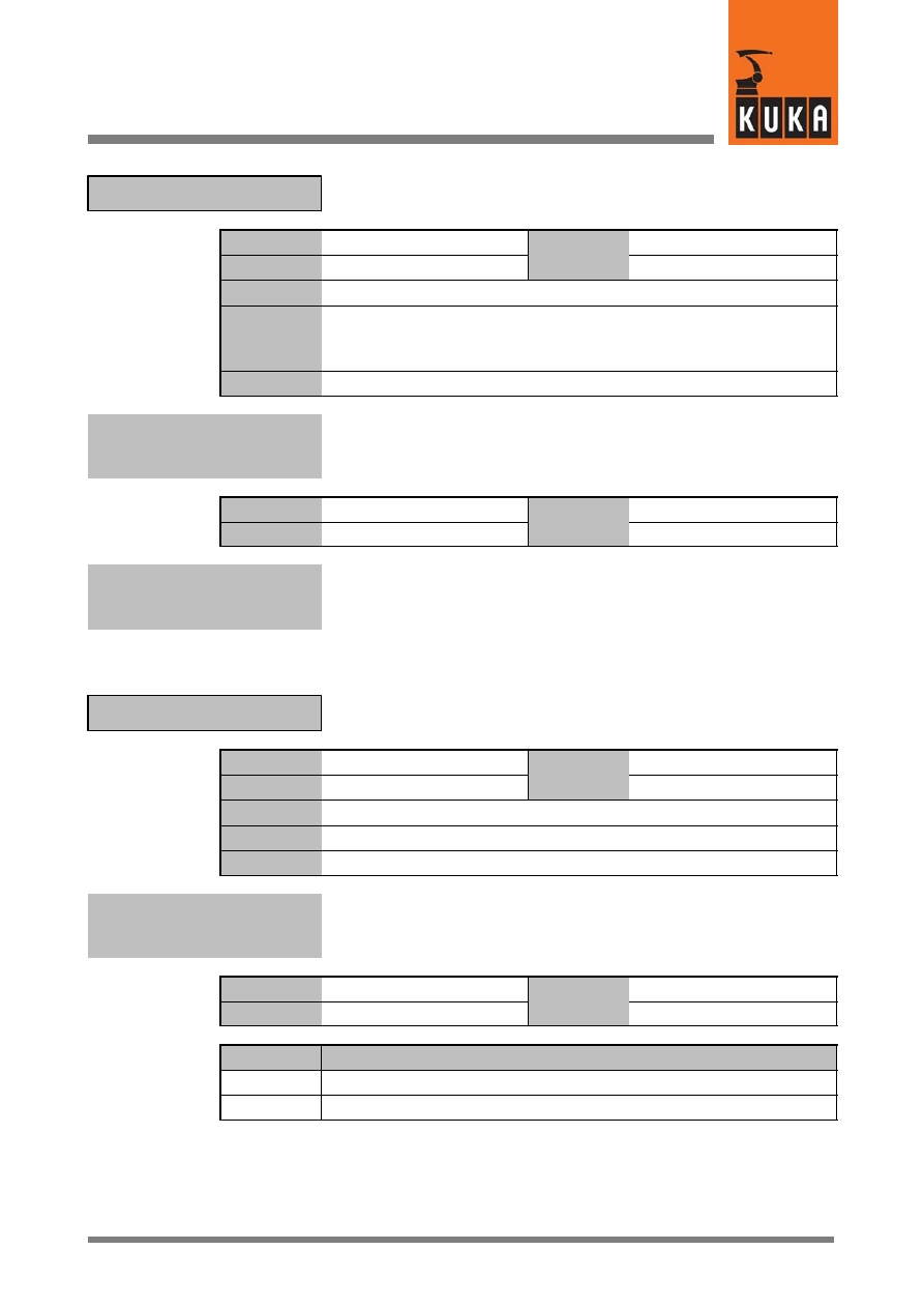
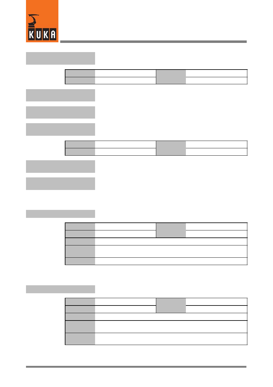
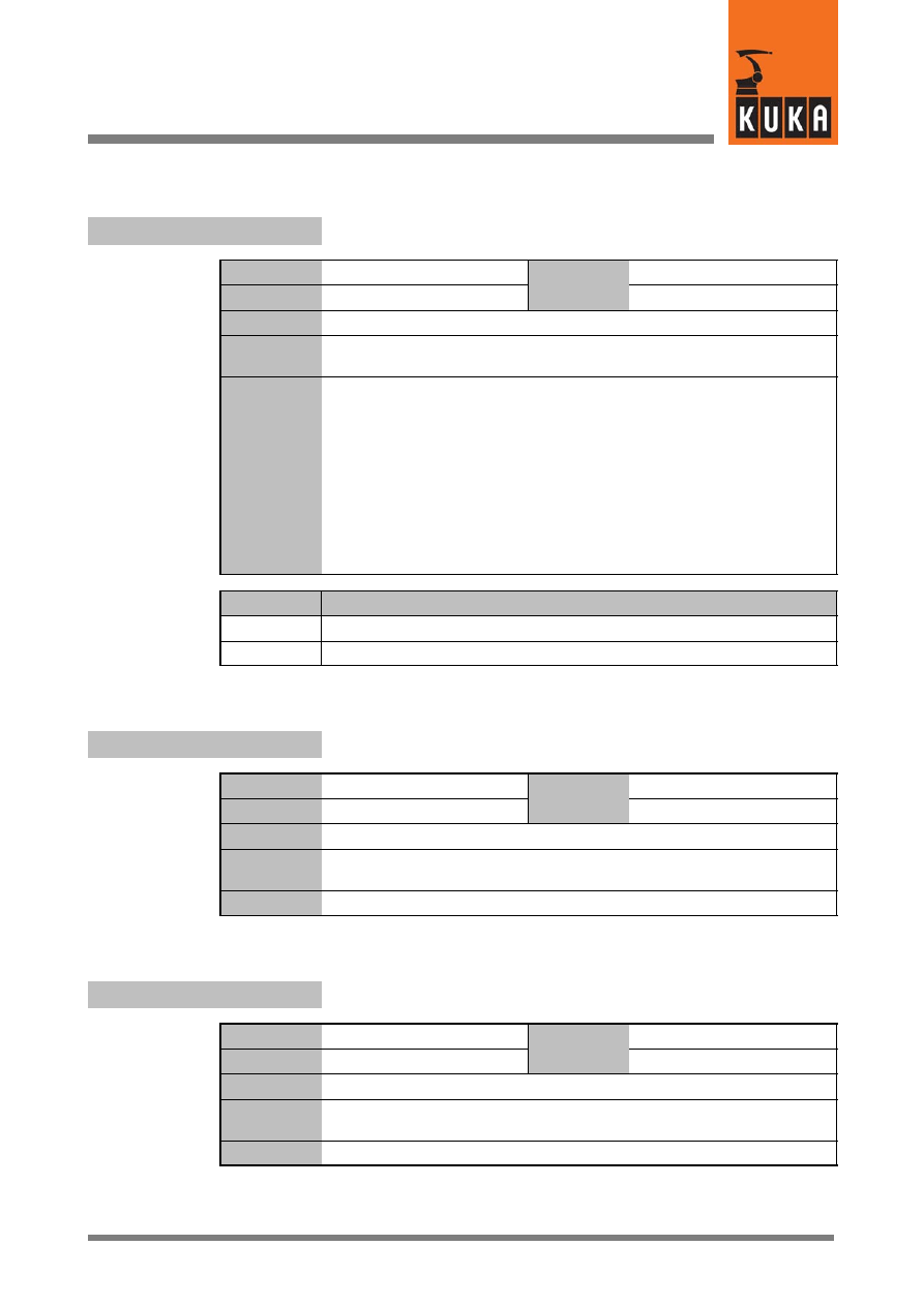
Table entries:
Data type
Real, Integer, Boolean, Character, Structure, Signal declaration, Enum,
Frame, Array
Unit
ms, mm, m/s
2
, s, °, %, V, A, increments, bits, bit sequence, motion
instructions
In file
KRC\Roboter\KRC \R1\Mada\...
...
\Steu\Mada\...
Original line
Source text
;Comment
Comments
Functional description
Value min.
max.
Minimum and maximum values depending on the specific data type
Option
Options depending on the data type (TRUE, FALSE, 1, 2, etc.)
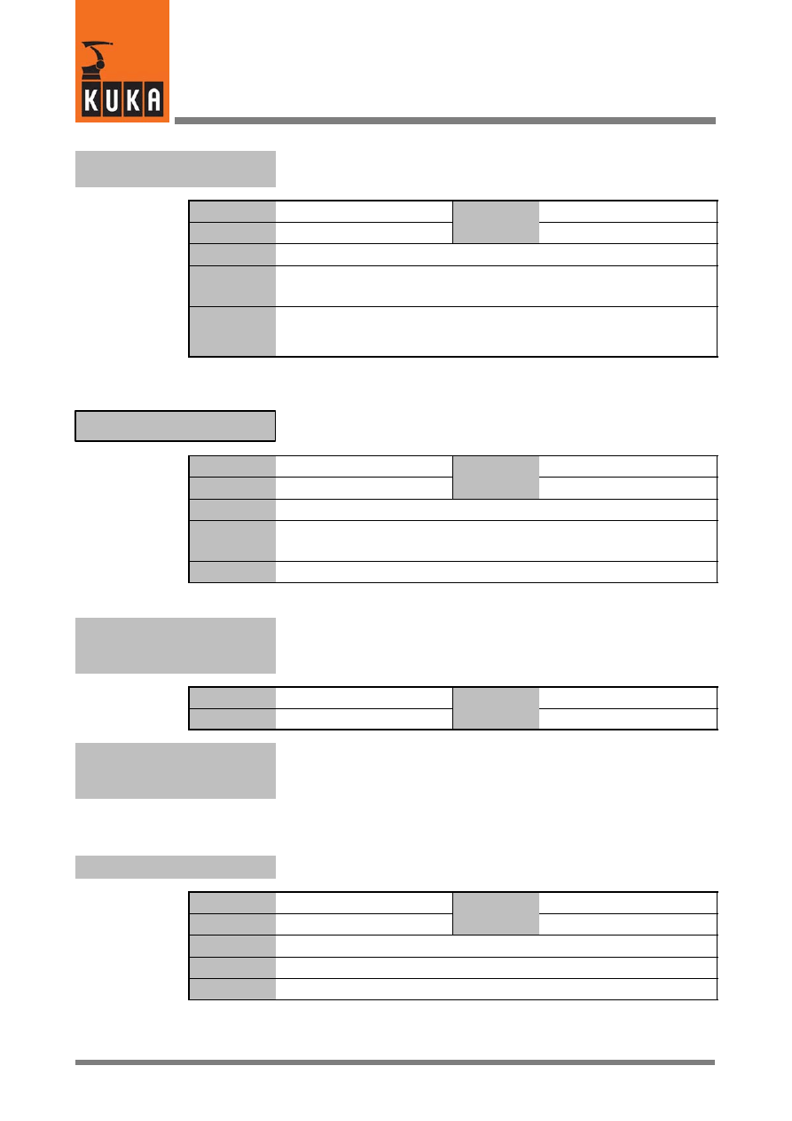
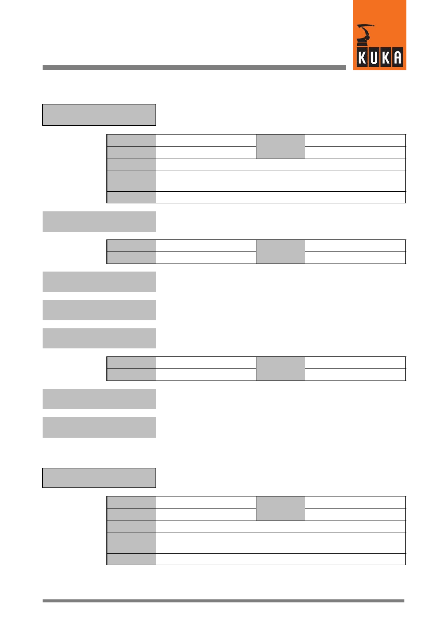
A group of system variables is indicated at the beginning with a framed name box:
Function of the variable
Variable name
Data type
Structure
Value
min.
Unit
Value
max.
In file
Original line
Comments
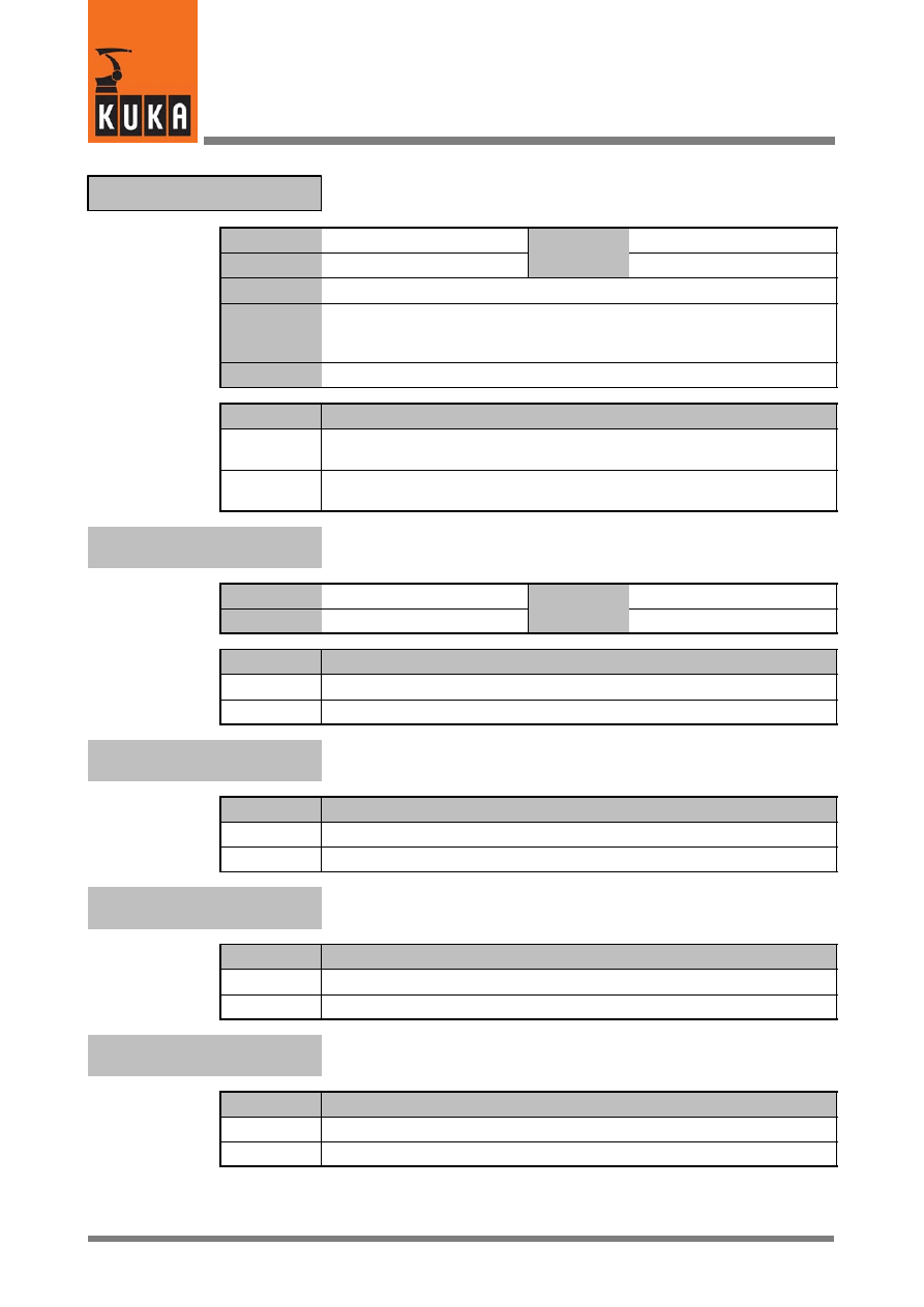
If the description contents of subsequent system variables remain the same, only their title
lines are displayed.
Variable name.1
Function of the variable
If there is a change, the corresponding section of the table is shown under the title line. This
change then applies to all subsequent variables of the group.
Variable name.2
Function of the variable
Data type
Real
Value
min. 0
Unit
mm, °
Value
max.
Variable name.3
Function of the variable
2
A
7 of 170
SysVar 08.02.03 en
2
A
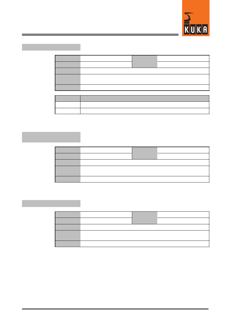
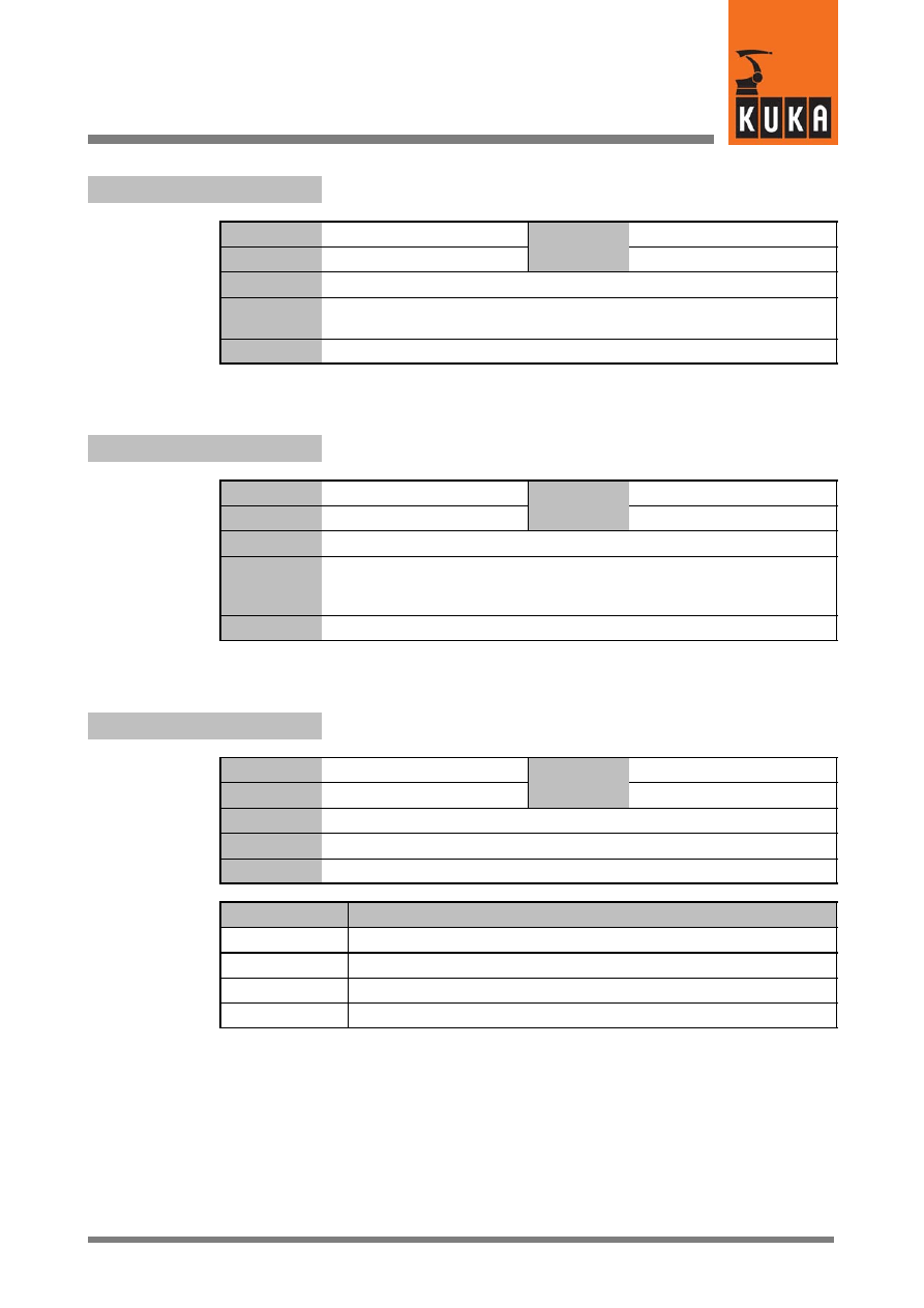
$A4PAR
Set axis 4 parallel to the last rotational main axis
Data type
Integer
Value
min.
Unit
Value
max.
In file
R1\Mada\$machine.dat
Original line
INT $A4PAR
Comments
Options
Effect
0
Not set
1
Set
$ABS_ACCUR
Switch absolutely accurate robot model on/off
Data type
Boolean
Value
min.
Unit
Value
max.
In file
------
Original line
BOOL $ABS_ACCUR=FALSE
;Absolutgenaues Robotermodell
Comments
Options
Effect
TRUE
Switched on
FALSE
Switched off
$ABS_CONVERT
Conversion of point coordinates into absolutely accurate robot
model
Data type
Boolean
Value
min.
Unit
Value
max.
In file
Steu\Mada\$custom.dat
Original line
BOOL $ABS_CONVERT=FALSE
;Konvertierung der Punktkoordinaten
Comments
Options
Effect
TRUE
FALSE
System Variables
8 of 170
SysVar 08.02.03 en
$ABS_RELOAD
Reload absolutely accurate robot model
Data type
Boolean
Value
min.
Unit
Value
max.
In file
Steu\Mada\$operate.dat
Original line
BOOL $ABS_RELOAD
Comments
$ACC
Path, swivel and rotational accelerations in the advance run
Data type
Structure
Value
min.
Unit
Value
max.
In file
------
Original line
DECL CP $ACC
Comments
Accelerations in the advance run
CP = m/s
2
, ORI1 = °/s
2
, ORI2 = °/s
2
$ACC_ACT_MA
Limit value of axial command acceleration
Data type
Integer
Value
min.
Unit
%
Value
max.
In file
R1\Mada\$machine.dat
Original line
INT $ACC_ACT_MA=250
;Grenzwert Sollbeschleunigung [%]
Comments
$ACC_AXIS[n]
Acceleration of the axes in the advance run
Data type
Integer
Value
min.
Unit
%
Value
max.
In file
------
Original line
INT $ACC_AXIS[n]
Beschleunigung der Achsen [%] Vorlauf
Comments
[n] = [1] ... [6] axes A1 ... A6
2
A (Fortsetzung)
9 of 170
SysVar 08.02.03 en
$ACC_AXIS_C[n]
Acceleration of the axes in the main run
Data type
Integer
Value
min.
Unit
%
Value
max.
In file
R1\Mada\$operate.dat
Original line
INT $ACC_AXIS_C[n]
Beschleunigung der Achsen [%] Hauptlauf
Comments
[n] = [1] ... [6] axes A1 ... A6
$ACC_C
Path, swivel and rotational accelerations in the main run
Data type
Structure
Value
min.
Unit
Value
max.
In file
R1\Mada\$operate.dat
Original line
DECL CP $ACC_C
Comments
Accelerations in the main run
CP = m/s
2
, ORI1 = °/s
2
, ORI2 = °/s
2
$ACC_CAR_ACT
The current values of the acceleration components and the total
acceleration
Data type
Frame
Value
min.
Unit
m/s
2
Value
max.
In file
R1\Mada\$operate.dat
Original line
DECL ACC_CAR $ACC_CAR_ACT
Comments
The X, Y and Z components of “$ACC_CAR_ACT” contain the acceleration
components along the axes of “$ACC_CAR_TOOL”. “$ACC_CAR_
ACT.ABS” contains the associated total acceleration value. Components A,
B and C are each set to “0”.
This variable is write--protected.
Acceleration due to gravity (9.81 m/s
2
) is automatically calculated into the
acceleration caused by the motion.
System Variables
10 of 170
SysVar 08.02.03 en
$ACC_CAR_LIMIT
Used to set the maximum permissible value for the acceleration
components and the total acceleration
Data type
Frame
Value
min.
Unit
m/s
2
Value
max.
In file
R1\Mada\$machine.dat
Original line
DECL ACC_CAR $ACC_CAR_LIMIT={X 0.0,Y 0.0,Z 0.0,A 0.0,B 0.0,C
0.0,ABS 0.0}
Comments
If the variable “$ACC_CAR_STOP” is set to “TRUE”, then if the acceleration
value is exceeded the robot is stopped (ramp--down braking) and an
acknowledgement message is generated.
The values can only be modified by editing the machine data.
$ACC_CAR_MAX
Saves the greatest absolute values of “$ACC_CAR_ACT”
Data type
Frame
Value
min.
Unit
Value
max.
In file
R1\Mada\$machine.dat
Original line
DECL ACC_CAR $ACC_CAR_MAX
Comments
This variable can be set to “0” to determine the maximum values.
$ACC_CAR_STOP
The robot can be stopped if “$ACC_CAR_LIMIT” is exceeded
Data type
Boolean
Value
min.
Unit
Value
max.
In file
R1\Mada\$machine.dat
Original line
BOOL $ACC_CAR_STOP=FALSE
Comments
Activates or deactivates the stop reaction when the value specified in
“$ACC_CAR_LIMIT” is exceeded.
The values can only be modified by editing the machine data.
Options
Effect
TRUE
Stop reaction is activated.
FALSE
Stop reaction is deactivated.
2
A (Fortsetzung)
11 of 170
SysVar 08.02.03 en
$ACC_CAR_TOOL
A point on the tool mounted on the robot at which the current
effective acceleration is measured
Data type
Frame
Value
min.
Unit
Value
max.
In file
R1\Mada\$machine.dat
Original line
FRAME $ACC_CAR_TOOL={x 0.0,y 0.0,z 0.0,a 0.0,b 0.0,c 0.0}
Comments
In the same way as “$TOOL”, $ACC_CAR_TOOL is also specified relative
to the flange by means of the X, Y and Z coordinates. The angles of rotation
A, B and C indicate the positions of the 3 axes of the coordinate system in
which the acceleration components are then specified. The individual
acceleration components and the total acceleration are all evaluated
cyclically.
Acceleration caused by gear unit torsion or flexion of the robot is not taken
into consideration. These values can only be modified by editing the
machine data.
$ACC_EXTAX[6]
Acceleration of the external axes in the advance run
Data type
Integer
Value
min.
Unit
%
Value
max.
In file
------
Original line
INT $ACC_EXTAX[6]
;Beschleunigung der externen Achsen [%] Vorlauf
Comments
$ACC_EXTAX_C[6]
Acceleration of the external axes in the main run
Data type
Integer
Value
min.
Unit
%
Value
max.
In file
------
Original line
INT $ACC_EXTAX_C[6]
;Beschleunigung der externen Achsen [%] Hauptlauf
Comments
System Variables
12 of 170
SysVar 08.02.03 en
$ACC_MA
Maximum values for path acceleration, swivel acceleration and
rotational acceleration
Data type
Structure
Value
min.
Unit
Value
max.
In file
R1\Mada\$machine.dat
Original line
DECL CP $ACC_MA={CP 4.6,ORI1 200.0,ORI2 200.0}
Comments
CP
= Max. path acceleration [m/s
2
],
ORI1 = Max. swivel acceleration [°/s
2
],
ORI2 = Max. rotational acceleration [°/s
2
]
When calculating the values, make sure that no axis goes to current
limitation.
$ACC_OV
Data for acceleration with changes of override
Data type
Structure
Value
min.
Unit
Value
max.
In file
R1\Mada\$machine.dat
Original line
DECL CP $ACC_MA={CP 4.6,ORI1 200.0,ORI2 200.0}
Comments
CP
= Path acceleration with change of override [m/s
2
],
ORI1 = Swivel acceleration with change of override [°/s
2
],
ORI2 = Rotational acceleration with change of override [°/s
2
]
$ACT_BASE
Number of the current BASE system
Data type
Integer
Value
min.
Unit
Value
max.
In file
------
Original line
INT $ACT_BASE
;Aktuelle Base--Nummer
Comments
$ACT_EX_AX
Number of the current external base kinematic system
Data type
Integer
Value
min.
Unit
Value
max.
In file
------
Original line
INT $ACT_EX_AX
;Aktuelle externe Kinematik
Comments
2
A (Fortsetzung)
13 of 170
SysVar 08.02.03 en
$ACT_TOOL
Number of the current tool coordinate system
Data type
Integer
Value
min.
Unit
Value
max.
In file
------
Original line
INT $ACT_TOOL
;Aktuelle Toolnummer
Comments
$ACT_VAL_DIF
Max. permissible difference of encoder actual values when switching
on system
Data type
Integer
Value
min.
Unit
Increments
Value
max.
In file
R1\Mada\$machine.dat
Original line
INT $ACT_VAL_DIF
;Geberistwertdifferenz [Inkr]
Comments
If the limit values are exceeded, the message “Perform mastering”
appears.
$ADAP_ACC
Activation of acceleration adaptation
Data type
Enum
Value
min.
Unit
Value
max.
In file
R1\Mada\$robcor.dat
Original line
DECL ADAP_ACC $ADAP_ACC=#STEP1
;Beschleunigungsanpassung
(#NONE, #STEP1 )
Comments
*) #STEP1 and #STEP2 require valid dynamic data ($DYN_DAT)
Options
Effect
#NONE
Not activated
#STEP1
Dynamic model without kinetic energy *)
#STEP2
Dynamic model with kinetic energy *)
System Variables
14 of 170
SysVar 08.02.03 en
$ADVANCE
Specification of the advance run (max. 5 motion blocks)
Data type
Integer
Value
min. 0
Unit
Motion blocks
Value
max. 5
In file
------
Original line
INT $ADVANCE
;Vorlauf [max. 5 Bewegungssätze]
Comments
$ALARM_STOP
Signal declaration for short--circuit braking (dynamic braking)
Data type
Signal declaration
Value
min.
Unit
Value
max.
In file
Steu\Mada\$machine.dat
Original line
SIGNAL $ALARM_STOP $OUT[1013]
Comments
$ANA_DEL_FLT
Analog output filter
Data type
Enum
Value
min.
Unit
Value
max.
In file
R1\Mada\$machine.dat
Original line
DECL SW_ONOFF $ANA_DEL_FLT=#OFF
Comments
Options
Effect
#ON
Switched on
#OFF
Switched off
$ANIN[n]
Analog inputs
Data type
Real
Value
min. --1.0
Unit
V
Value
max. +1.0
In file
------
Original line
REAL $ANIN[n]
Comments
[n] = [1] ... [8]
--1.0 ----> --10 V
+1.0 ----> +10 V
2
A (Fortsetzung)
15 of 170
SysVar 08.02.03 en
$ANOUT[n]
Analog outputs
Data type
Real
Value
min. --1.0
Unit
V
Value
max. +1.0
In file
------
Original line
REAL $ANOUT[n]
Comments
[n] = [1] ... [16]
--1.0 ----> --10 V
+1.0 ----> +10 V
$APO_DIS_PTP[n]
Maximum approximation distance for PTP axis[
n
]
Data type
Real
Value
min.
Unit
mm, °
Value
max.
In file
R1\Mada\$machine.dat
Original line
REAL $APO_DIS_PTP[
n
]
Comments
[n] = [1] ... [6]:
axis A1 ... A6
[n] = [7] ... [12]: external axis E1 ... E6
Motion input for asynchronous external axes E1 -- E6,
negative or positive direction
$ASYNC_AX
Data type
Signal declaration
Value
min.
Unit
Value
max.
In file
Steu\Mada\$machine.dat
Original line
Comments
$ASYNC_AX1_M
...
$ASYNC_AX6_M
Motion input for asynchronous external axes E1 -- E6,
negative direction
Original line
SIGNAL $ASYNC_AX1_M $IN[1026]
...
SIGNAL $ASYNC_AX6_M $IN[1026]

System Variables
16 of 170
SysVar 08.02.03 en
$ASYNC_AX1_P
...
$ASYNC_AX6_P
Motion input for asynchronous external axes E1 -- E6,
positive direction
Original line
SIGNAL $ASYNC_AX1_P $IN[1026]
...
SIGNAL $ASYNC_AX6_P $IN[1026]
$ASYNC_AXIS
Bit arrays to switch external axes to asynchronous mode
Data type
Integer
Value
min.
Unit
Value
max.
In file
------
Original line
INT $ASYNC_AXIS
;Aktive asynchrone Zusatzachsen
Comments
When $ASYNC_AXIS is assigned in a KRL program, the newly--defined
asynchronous axes are valid from this position until a new assignment is
made.
When $ASYNC_AXIS is defined, the advance run will be stopped if the va-
lue of $ASYNC_AXIS changes. Before a new value of $ASYNC_AXIS is
saved, the system will wait until all synchronous motions (through advance
run stop) and all asynchronous motions have been completed, and all axes
are in position. Thus the instruction “$ASYNC_AXIS=...” can be used –
along with the system variable $ASYNC_STATE – to synchronize in time
synchronous and asynchronous motions.
$ASYNC_AXIS can only be modified in the KRL program, and not in the in-
terrupt or in the SUBMIT interpreter.
The bits correspond to the external axes in ascending order:
Bit 0 = external axis 1,
Bit 1 = external axis 2, etc.
If the bit is set, the external axis will be switched to asynchronous mode; if it
is reset, the external axis will be switched back to synchronous mode.
Options
Effect
Bit = 1
The corresponding external axis is switched to asynchronous mode
Bit = 0
The corresponding external axis is switched to synchronous mode

2
A (Fortsetzung)
17 of 170
SysVar 08.02.03 en
$ASYNC_FLT
Filter for asynchronous external axes
Data type
Integer
Value
min. 0
Unit
ms
Value
max. 16
In file
------
Original line
INT $ASYNC_FLT
Comments
The value of $ASYNC_FLT is the filter length in milliseconds for all asyn-
chronously coordinated motions; it corresponds to the system variable
$FILTER for synchronous motions.
$ASYNC_MODE
Mode for asynchronous external axes
Data type
Integer
Value
min. 0
Unit
Value
max. 16
In file
Steu\Mada\$custom.dat
Original line
INT $ASYNC_MODE=’B0000’
;Mode für asynchrone Zusatzachsen
Comments
In the machine data of the controller, the bit mask $ASYNC_MODE can
be used to set various asynchronous motion execution modes.
It is not possible to change modes while the robot controller is running.
The modes can be combined in any way desired.
Certain modes must be set in order to use special applications.
In the standard setting (default mode) no $ASYNC_MODE bits are set.
Only bit 0 is used at this time:
Bit 0 = 0 (1st bit): default mode
Bit 0 = 1 (1st bit): mode 1
Bit 1 = (2nd bit): mode 2 block selection response
$ASYNC_OPT
Option flag for “Asynchronous axes are possible”
Data type
Boolean
Value
min.
Unit
Value
max.
In file
Steu\Mada\$option.dat
Original line
BOOL $ASYNC_OPT=FALSE
Comments
Options
Effect
TRUE
Asynchronous axes possible
FALSE
Asynchronous axes not possible
System Variables
18 of 170
SysVar 08.02.03 en
$ASYNC_STATE
Current asynchronous motion execution state
Data type
Enum
Value
min.
Unit
Value
max.
In file
------
Original line
DECL ASYNC_STATE $ASYNC_STATE
;Zustand der asynchronen Achsen
Comments
$ASYNC_STATE can be used to check the current asynchronous motion
execution state.
The value is read--only; no assignments are possible.
Asynchronous and “normal” robot motions can be synchronized using
this variable.
Options
Effect
#BUSY
Asynchronous motions active, stopped or temporarily stored.
#IDLE
No asynchronous motions active or stopped (queue is empty); last
motion terminated without an interrupt.
#CANCELLED No asynchronous motions active or stopped (queue is empty); last
motion was canceled.
#PEND
Asynchronous motion is planned, but is not currently being executed
$ASYNC_T1_FAST
Control of the velocity reduction factor in Test1 mode
Data type
Integer
Value
min.
Unit
Value
max.
In file
R1\Mada\$machine.dat
Original line
INT $ASYNC_T1_FAST=’B0000’
;Geschw.--Red. Deaktiviert ( T1 )
Comments
Options
Effect
0
Activated
1
Deactivated
2
A (Fortsetzung)
19 of 170
SysVar 08.02.03 en
$ASYS
Assignment of the jog keys
Data type
Enum
Value
min.
Unit
Value
max.
In file
------
Original line
DECL ASYS $ASYS
;Verfahrtastenbelegung (ROBOT = Roboter, EXTAX = Externe Achsen)
Comments
Options
Effect
#ROBOT
Robot axes A1 -- A6
#EXTAX
External axes E1 -- E6
#EXTAX2
External kinematic system
$AUT
Signal declaration “Automatic mode”
Data type
Signal declaration
Value
min.
Unit
Value
max.
In file
Steu\Mada\$machine.dat
Original line
SIGNAL $AUT $OUT[995]
;Betriebsart Automatik
Comments
$AUX_POWER
Signal declaration for external power supply
Data type
Signal declaration
Value
min.
Unit
Value
max.
In file
Steu\Mada\$machine.dat
Original line
SIGNAL $AUX_POWER $IN[1026]
;Externe Spannungsversorgung aktiv
Comments
If “$AUX_POWER” has the value “TRUE”, the external power supply is
active; if the value is “FALSE”, the external power supply is not active.
System Variables
20 of 170
SysVar 08.02.03 en
$AX_SIM_ON
Simulation of the closed speed control loop for the individual axes
on a desktop PC
Data type
Integer
Value
min.
Unit
Value
max.
In file
R1\Mada\$machine.dat
Original line
INT $AX_SIM_ON=’B111111’
;Achssimulation
Comments
Bit sequence:
LSB: Axis 1
MSB: Axis 12
Current axis--specific robot position
$AXIS_ACT
Data type
Structure
Value
min.
Unit
mm, °
Value
max.
In file
------
Original line
E6AXIS $AXIS_ACT
;Aktuelle Roboterposition achsspezifisch [mm,Grad]
Comments
$AXIS_ACT.A1
...
$AXIS_ACT.A6
Current axis--specific robot position, axis 1 -- 6
Data type
Real
Value
min. 0
Unit
mm, °
Value
max.
$AXIS_ACT.E1
...
$AXIS_ACT.E6
Current axis--specific robot position, external axis 1 -- 6
$AXIS_ACTMOD
Display of axis angle modulo 180°
Data type
Structure
Value
min.
Unit
Value
max.
In file
------
Original line
E6AXIS $AXIS_ACTMOD
Comments
2
A (Fortsetzung)
21 of 170
SysVar 08.02.03 en
Start position of the current motion block, axis--specific
$AXIS_BACK
Data type
Structure
Value
min.
Unit
mm, °
Value
max.
In file
------
Original line
E6AXIS $AXIS_BACK
;Anfangsposition des aktuellen Bewegungssatzes achsspezifisch
[mm,Grad]
Comments
$AXIS_BACK.A1
...
$AXIS_BACK.A6
Start position of the current motion block,
axis A1 -- A6
Data type
Real
Value
min. 0
Unit
mm, °
Value
max.
$AXIS_BACK.E1
...
$AXIS_BACK.E6
Start position of the current motion block,
external axis E1 -- E6
Display whether axis is referenced
$AXIS_CAL
Data type
Structure
Value
min.
Unit
Value
max.
In file
------
Original line
DECL AXIS_CAL $AXIS_CAL
Comments
Display of referenced axes
$AXIS_CAL.A1
...
$AXIS_CAL.A6
Display whether axis A1 ... A6 is referenced
Data type
Boolean
Value
min.
Unit
Value
max.
Options
Effect
TRUE
Axis is referenced
FALSE
Axis is not referenced
System Variables
22 of 170
SysVar 08.02.03 en
$AXIS_CAL.E1
...
$AXIS_CAL.E6
Display whether external axis E1 ... E6 is referenced
$AXIS_DIR[n]
Direction of rotation of axis[n]
Data type
Integer
Value
min.
Unit
Value
max.
In file
R1\Mada\$machine.dat
Original line
INT $AXIS_DIR[n]
Comments
[n] = [1] ... [6]:
axis A1 ... A6
[n] = [7] ... [12]: external axis E1 ... E6
Options
Effect
1
Positive direction
--1
Negative direction
Target position of the current motion block, axis--specific
$AXIS_FOR
Data type
Structure
Value
min.
Unit
mm, °
Value
max.
In file
------
Original line
E6AXIS $AXIS_FOR
;Zielposition des aktuellen Bewegungssatzes achsspezifisch [mm,Grad]
Comments
$AXIS_FOR.A1
...
$AXIS_FOR.A6
Target position of the current motion block, axis A1 ... A6
Data type
Real
Value
min. 0
Unit
mm, °
Value
max.
$AXIS_FOR.E1
...
$AXIS_FOR.E6
Target position of the current motion block, external axis E1 ... E6
2
A (Fortsetzung)
23 of 170
SysVar 08.02.03 en
$AXIS_HOME[5]
Definition of the various home positions
Data type
Array
Value
min.
Unit
Value
max.
In file
R1\Mada\$machine.dat
Original line
E6AXIS $AXIS_HOME[5]
Comments
Incremental actual values of the axes
$AXIS_INC
Data type
Structure
Value
min.
Unit
Increments
Value
max.
In file
------
Original line
DECL AXIS_INC $AXIS_INC
Comments
Indication of the axis position in increments.
$AXIS_INC.I1
...
$AXIS_INC.I6
Incremental actual value, axis A1 ... A6
Data type
Integer
Value
min. 0
Unit
Increments
Value
max.
$AXIS_INC.E1
...
$AXIS_INC.E6
Incremental actual value, external axis E1 ... E6
Robot position at the time of an interrupt
$AXIS_INT
Data type
Structure
Value
min.
Unit
mm, °
Value
max.
In file
------
Original line
E6AXIS $AXIS_INT
;Unterbrechungsposition achsspezifisch [mm,Grad]
Comments
System Variables
24 of 170
SysVar 08.02.03 en
$AXIS_INT.A1
...
$AXIS_INT.A6
Robot position at the time of an interrupt,
axis A1 ... A6
Data type
Real
Value
min. 0
Unit
mm, °
Value
max.
$AXIS_INT.E1
...
$AXIS_INT.E6
Robot position at the time of an interrupt,
external axis E1 ... E6
Display whether axis is mastered
$AXIS_JUS
Data type
Structure
Value
min.
Unit
Value
max.
In file
------
Original line
DECL AXIS_CAL $AXIS_JUS
;Anzeige justierter Achsen
Comments
$AXIS_JUS.A1
...
$AXIS_JUS.A6
Display whether axis A1 ... A6 is mastered
Data type
Boolean
Value
min.
Unit
Value
max.
Options
Effect
TRUE
Axis mastered
FALSE
Axis not mastered
$AXIS_JUS.E1
...
$AXIS_JUS.E6
Display whether external axis E1 ... E6 is mastered
$AXIS_RESO
Resolution of the position sensing system
Data type
Integer
Value
min.
Unit
Increments / revolution
Value
max.
In file
R1\Mada\$machine.dat
Original line
INT $AXIS_RESO[12]
;Auflösung des Meßsystems Achse(i) (i=1:A1, i=7:E1) [Inkr]
Comments
Number of pulses per revolution of the encoder
2
A (Fortsetzung)
25 of 170
SysVar 08.02.03 en
Axis positions when leaving the programmed path, axis--specific
$AXIS_RET
Data type
Structure
Value
min.
Unit
mm, °
Value
max.
In file
------
Original line
E6AXIS $AXIS_RET
;Rückpositionieren achsspezifisch [mm,Grad]
Comments
$AXIS_RET.A1
...
$AXIS_RET.A6
Position of axis A1 ... A6 when leaving the programmed path
Data type
Character
Value
min. 0
Unit
mm, °
Value
max.
$AXIS_RET.E1
...
$AXIS_RET.E6
Position of external axis E1 ... E6 when leaving the programmed path
$AXIS_SEQ[n]
Change in sequence of axis ... to axis ...
Data type
Integer
Value
min.
Unit
Value
max.
In file
R1\Mada\$machine.dat
Original line
INT $AXIS_SEQ[n]
Comments
[n] = [1] ... [6]: axis A1 ... A6
[n] = [7] ... [12]: external axis E1 ... E6
System Variables
26 of 170
SysVar 08.02.03 en
$AXIS_TYPE[n]
Axis identification
Data type
Integer
Value
min.
Unit
Value
max.
In file
R1\Mada\$machine.dat
Original line
INT $AXIS_TYPE[n]
Comments
[n] = [1] ... [6]: axis A1 ... A6
[n] = [7] ... [12]: external axis E1 ... E6
Options
Effect
1
Linear
2
Spindle
3
Rotational
4
Finitely rotating
5
Infinitely rotating
$AXWORKSPACE[n]
Definition of axis--specific workspace monitoring
Data type
Structure
Value
min.
Unit
Value
max.
In file
R1\Mada\$machine.dat
Original line
DECL AXBOX$AXWORKSPACE[n]
Comments
[n] = [1] ... [8]
2
A (Fortsetzung)
27 of 170
SysVar 08.02.03 en
$AXWORKSPACE[n].MODE
Functional principle of the axis--specific workspace monitoring
function
Data type
Enum
Value
min.
Unit
Value
max.
In file
R1\Mada\$machine.dat
Original line
DECL AXBOX$AXWORKSPACE[n]
Comments
[n] = [1] ... [8]
Options
Effect
#OFF
Work envelope monitoring deactivated
#INSIDE
The output is set if the TCP is located inside the work envelope
#OUTSIDE
The output is set if the TCP is located outside the work envelope
#INSIDE_STOP
The output is set and the robot stopped if the TCP is located inside
the work envelope
#OUTSIDE_STOP The output is set and the robot stopped if the TCP is located outside
the work envelope
$AXWORKSPACE[n].STATE
Violation of the axis--specific workspace
Data type
Boolean
Value
min.
Unit
Value
max.
Options
Effect
TRUE
The workspace has been violated
FALSE
The workspace has not been violated
$AXWORKSPACE_NAMEn[]
Name of the particular axis--specific workspace
Data type
Character
Value
min.
Unit
Value
max.
In file
R1\Mada\$machine.dat
Original line
CHAR $AXWORKSPACE_NAMEn[24]
$AXWORKSPACE_NAMEn[]=”AXWORKSPACE_NAME n”
Comments
[n] = [1] ... [8]

System Variables
28 of 170
SysVar 08.02.03 en
$AXWORKSTATE1
...
$AXWORKSTATE8
Signal declaration “Violation of workspace”
Data type
Signal declaration
Value
min.
Unit
Value
max.
In file
Steu\Mada\$machine.dat
Original line
SIGNAL $AXWORKSTATE1 $OUT[969]
.
.
SIGNAL $AXWORKSTATE8 $OUT[976]
; Ausgang der Achsarbeitsraumüberwachung .
Comments
Options
Effect
$OUT[n]
Output 1 ... 4096
FALSE
Outputs that are not required can be set to “FALSE”,
e.g. SIGNAL $AXWORKSTATE1 FALSE
3
B
29 of 170
SysVar 08.02.03 en
3
B
Offset and rotation of the base coordinate system in relation to the
world coordinate system in the advance run
$BASE
Data type
Structure
Value
min.
Unit
Value
max.
In file
R1\Mada\$operate.dat
Original line
FRAME $BASE
;Basis im Weltkoordinatensystem Vorlauf
Comments
$BASE.A
Rotation of the base coordinate system about the Z axis in relation
to the world coordinate system in the advance run
Data type
Real
Value
min.
Unit
°
Value
max.
$BASE.B
Rotation of the base coordinate system about the Y axis in relation
to the world coordinate system in the advance run
$BASE.C
Rotation of the base coordinate system about the X axis in relation
to the world coordinate system in the advance run
$BASE.X
Offset of the base coordinate system in the X direction in relation
to the world coordinate system in the advance run
Data type
Real
Value
min.
Unit
mm
Value
max.
$BASE.Y
Offset of the base coordinate system in the Y direction in relation
to the world coordinate system in the advance run
$BASE.Z
Offset of the base coordinate system in the Z direction in relation
to the world coordinate system in the advance run
Offset and rotation of the base coordinate system in relation to the
world coordinate system in the main run
$BASE_C
Data type
Structure
Value
min.
Unit
Value
max.
In file
------
Original line
FRAME $BASE_C
;Basis im Weltkoordinatensystem Hauptlauf
Comments
System Variables
30 of 170
SysVar 08.02.03 en
$BASE_C.A
Rotation of the base coordinate system about the Z axis in relation
to the world coordinate system in the main run
Data type
Real
Value
min.
Unit
°
Value
max.
$BASE_C.B
Rotation of the base coordinate system about the Y axis in relation
to the world coordinate system in the main run
$BASE_C.C
Rotation of the base coordinate system about the X axis in relation
to the world coordinate system in the main run
$BASE_C.X
Offset of the base coordinate system in the X direction in relation
to the world coordinate system in the main run
Data type
Real
Value
min.
Unit
mm
Value
max.
$BASE_C.Y
Offset of the base coordinate system in the Y direction in relation
to the world coordinate system in the main run
$BASE_C.Z
Offset of the base coordinate system in the Z direction in relation
to the world coordinate system in the main run
$BASE_KIN
External kinematic / axes in base
Data type
Character
Value
min.
Unit
Value
max.
In file
------
Original line
CHAR $BASE_KIN[29]
;Externe Kinematik / Achsen in Base
Comments
$BOUNCE_TIME
Bounce time for EMT signals
Data type
Integer
Value
min.
Unit
ms
Value
max.
In file
R1\Mada\$machine.dat
Original line
INT $BOUNCE_TIME
;Prellzeit für EMT--Taster [ms]
Comments
The signal is only accepted if it remains stable over the entire time
period defined in $BOUNCE_TIME.
3
B (Fortsetzung)
31 of 170
SysVar 08.02.03 en
$BRAKE_SIG
Bit array for axis brakes, A1 ... A6 and E1 ... E6
Data type
Integer
Value
min.
Unit
Value
max.
In file
------
Original line
INT $BRAKE_SIG
;Bit--Feld Bremsensignale
Comments
Options
Effect
0
Brake closed
1
Brake open
$BRK_DEL_COM
Time after which the axis brakes are closed on completion of posi-
tioning during jogging
Data type
Integer
Value
min.
Unit
ms
Value
max.
In file
R1\Mada\$machine.dat
Original line
INT $BRK_DEL_COM
;Bremsverzögerungszeitkommando--Modus [ms]
Comments
$BRK_DEL_EX
Brake delay time for external axes
Data type
Integer
Value
min.
Unit
ms
Value
max.
In file
R1\Mada\$machine.dat
Original line
INT $BRK_DEL_EX
;Bremsverzögerungszeit für Zusatzachsen
Comments

System Variables
32 of 170
SysVar 08.02.03 en
$BRK_DEL_PRO
Time after which the axis brakes are closed on completion of posi-
tioning in the program
Data type
Integer
Value
min.
Unit
ms
Value
max.
In file
R1\Mada\$machine.dat
Original line
INT $BRK_DEL_PRO
;Bremsverzögerungszeit im Programm [ms]
Comments
$BRK_MAX_TM
Maximum deceleration time for path--maintaining Emergency Stop
Data type
Integer
Value
min.
Unit
ms
Value
max.
In file
R1\Mada\$machine.dat
Original line
INT $BRK_MAX_TM
Comments
$BRK_MODE
Brake control mode
Data type
Integer
Value
min.
Unit
Value
max.
In file
R1\Mada\$machine.dat
Original line
INT $BRK_MODE=’B0101’
Comments
The bits are counted from right to left.
Bit 0:
Axes A 1 – A 6 close at command end (bit 0 = 1) /
do not close (bit 0 = 0)
Bit 1:
Axes A 1 – A 6 close individually
1)
(bit 1 = 1) /
together (bit 1 = 0)
Bit 2:
Axes A 1 – A 6 close during pauses in the motion (bit 2 = 1) /
do not close (bit 2 = 0)
Bit 3:
External axis brakes close during motion pauses
individually (bit 3 = 1) / together with axes A 1 – A 6 (bit 3 = 0)
1)
Special case
3
B (Fortsetzung)
33 of 170
SysVar 08.02.03 en
$BRK_OPENTM
Time delay of command value output after axis brakes have been
opened
Data type
Integer
Value
min.
Unit
ms
Value
max.
In file
R1\Mada\$machine.dat
Original line
INT $BRK_OPENTM
;Bremsöffnungszeit [ms]
Comments
$BUS_PAR
L2 bus interface (KRC32)
Data type
Structure
Value
min.
Unit
Value
max.
In file
Steu\Mada\$custom.dat
Original line
DECL BUS $BUS_PAR={PROTO 1,PROC 5,RCO 5,BL 128,PT 0,TS
1,BAUD 187500,TSL --1,MIN_TDSR --1,MAX_TDSR --1,TTR --1,HSA
--1,G --1,DFLT_SAP --1}
Comments
System Variables
34 of 170
SysVar 08.02.03 en
4
C
$CABLE2_MON
Additional motor cable monitoring
Data type
Boolean
Value
min.
Unit
Value
max.
In file
R1\Mada\$machine.dat
Original line
BOOL $CABLE2_MON=FALSE
Comments
Specifies whether the connection of the second motor cable should be
monitored (TRUE for special machines)
Options
Effect
TRUE
Monitoring activated
FALSE
Monitoring deactivated
$CAL_DIFF
Mastering difference for EMT mastering with check run
Data type
Integer
Value
min.
Unit
Value
max.
In file
------
Original line
INT $CAL_DIFF
;Justage--Differenz
Comments
Reference point offset between mathematical zero point and
encoder zero point
$CALP
Data type
Structure
Value
min. 0
Unit
Value
max.
In file
------
Original line
E6AXIS $CALP
;Referenzpunktverschiebung
Comments
4
C (Fortsetzung)
35 of 170
SysVar 08.02.03 en
$CALP.A1
...
$CALP.A6
Reference point offset between mathematical zero point and
encoder zero point, axis A1 ... A6
Data type
Real
Value
min. 0
Unit
°
Value
max.
$CALP.E1
...
$CALP.E6
Reference point offset between mathematical zero point and
encoder zero point, external axis E1 ... E6
$CIRC_TYPE
Orientation control with CIRC blocks in the advance run
Data type
Enum
Value
min.
Unit
Value
max.
In file
------
Original line
DECL CIRC_TYPE $CIRC_TYPE
;Bezugssystem für die Orientierungsinterpolation bei CIRC--Sätzen
(Vorlauf)
Comments
Options
Effect
#BASE
Space--related orientation control
#PATH
Path--related orientation control
$CIRC_TYPE_C
Orientation control with CIRC blocks in the main run
Data type
Enum
Value
min.
Unit
Value
max.
In file
------
Original line
DECL CIRC_TYPE $CIRC_TYPE_C
;Bezugssystem für die Orientierungsinterpolation bei CIRC--Sätzen
(Hauptlauf)
Comments
Options
Effect
#BASE
Space--related orientation control
#PATH
Path--related orientation control

System Variables
36 of 170
SysVar 08.02.03 en
$CMD
Display assignment number (handle) for command channel
Data type
Integer
Value
min.
Unit
Value
max.
In file
------
Original line
INT $CMD
Comments
$COM_NAME
Command which is to be processed after next start
Data type
Character
Value
min.
Unit
Value
max.
In file
------
Original line
CHAR $COM_NAME[486]
;Kommando, welches beim nächsten Start abgearbeitet wird
Comments
$COM_VAL_MI[n]
Limitation of command speed, axis[n]
Data type
Real
Value
min.
Unit
%
Value
max.
In file
R1\Mada\$machine.dat
Original line
REAL $COM_VAL_MI[n]
Comments
[n] = [1] ... [6]:
axis A1 ... A6
[n] = [7] ... [12]: external axis E1 ... E6
$CONF_MESS
Signal declaration “Reset acknowledgement messages”
Data type
Signal declaration
Value
min.
Unit
Value
max.
In file
Steu\Mada\$machine.dat
Original line
SIGNAL $CONF_MESS $IN[1026]
Comments
External confirmation
4
C (Fortsetzung)
37 of 170
SysVar 08.02.03 en
$COSYS
Coordinate system for jogging
Data type
Enum
Value
min.
Unit
Value
max.
In file
------
Original line
DECL COSYS $COSYS
Comments
Options
Effect
#AX
Motions are relative to the axis--specific coordinate system.
#CAR
Motions are relative to the Cartesian coordinate system.
$COUNT_I[n]
Freely usable integer variables
Data type
Integer
Value
min.
Unit
Value
max.
In file
------
Original line
INT $COUNT_I[n]
Comments
[n]=[1] ... [32]
Used as counters in the VW package
$COUP_COMP[N,D]
Axis coupling factors
Data type
Structure
Value
min.
Unit
Value
max.
In file
R1\Mada\$machine.dat
Original line
DECL FRA $COUP_COMP[6,6]
Comments
Axis coupling factor: N = numerator; D = denominator
System Variables
38 of 170
SysVar 08.02.03 en
$CP_VEL_TYPE
Reduction of the CP path velocity
Data type
Enum
Value
min.
Unit
Value
max.
In file
Steu\Mada\$custom.dat
Original line
DECL CP_VEL_TYPE $CP_VEL_TYPE=#CONSTANT
Comments
If the axis limit values are exceeded, the CP velocity is reduced.
Reduction is always active in Cartesian jogging.
Options
Effect
#Constant
No reduction
#VAR_T1
Reduction in jog mode SStep(T1)
#VAR_ALL
Reduction in all modes
$CPVELREDMELD
Generation of message if path velocity reduced
Data type
Real
Value
min.
Unit
Value
max.
In file
------
Original line
INT $CPVELREDMELD
Comments
The message contains the point name and the maximum reduction in the
specific motion command.
Options
Effect
0
Generation of message deactivated.
1
Generation of message in the event of block change in jog mode.
100
Generation of message in the event of block change in all modes.
$CURR_ACT
Actual current of axes 1 -- 12
Data type
Real
Value
min.
Unit
%
Value
max.
In file
------
Original line
REAL $CURR_ACT[12]
;Aktueller Motorstrom in %
Comments
Current value of current of axes 1 -- 12 in % of maximum servo drive
module current $CURR_MAX (--100% to +100%)
4
C (Fortsetzung)
39 of 170
SysVar 08.02.03 en
$CURR_CAL
Current calibration in the power module
Data type
Real
Value
min.
Unit
Value
max.
In file
R1\Mada\$machine.dat
Original line
REAL $CURR_CAL[12]
;Stromkalibrierung Powermodul (Stromwandler)
Comments
For KRC 1a and KRC 2, calibration =1
Options
Effect
1
High power
2
Medium / low power
4
Low power
$CURR_COM_EX
Current limitation for external axes in jog mode
Data type
Real
Value
min.
Unit
Value
max.
In file
R1\Mada\$machine.dat
Original line
REAL $CURR_COM_EX[6]
;Stromgrenze externer Achsen für Handverfahren
Comments
$CURR_LIM[n]
Current limitation, axis[n]
Data type
Integer
Value
min.
Unit
%
Value
max.
In file
R1\Mada\$machine.dat
Original line
INT $CURR_LIM[n]
Comments
[n] = [1] ... [6]: axis A1 ... A6
[n] = [7] ... [12]: external axis E1 ... E6
$CURR_MAX
Maximum effective current on power module output
Data type
Real
Value
min.
Unit
A
Value
max.
In file
R1\Mada\$machine.dat
Original line
REAL $CURR_MAX[12]
Comments
Effective current must be present
System Variables
40 of 170
SysVar 08.02.03 en
$CURR_MON[n]
Permissible rated current
Data type
Real
Value
min.
Unit
Value
max.
In file
R1\Mada\$machine.dat
Original line
REAL $CURR_MON[n]
;Zulässiger Nennstrom
Comments
Defines the limit for i
2
t monitoring for 55 °C
[n] = [1] ... [6]: axis A1 ... A6
[n] = [7] ... [12]: external axis E1 ... E6
$CURR_RED
Current limitation of axes 1 -- 12 in % of maximum current
Data type
Real
Value
min.
Unit
%
Value
max.
In file
------
Original line
REAL $CURR_RED[12,2]
Comments
1st digit:
axis
2nd digit:
1 = positive limit
2 = negative limit
$CYC_DEF1 ... 32
Input text for the corresponding cyclical flag
Data type
Character
Value
min.
Unit
Value
max.
In file
------
Original line
CHAR $CYC_DEF1[470]
...
CHAR $CYC_DEF32[470]
Comments
$CYCFLAG[n]
Cyclical flags
Data type
Boolean
Value
min.
Unit
Value
max.
In file
------
Original line
BOOL $CYCFLAG[32]
Comments
[n]=[1] ... [256]
There are 32 cyclical flags available; these flags are cyclically updated
independently of program execution. The default value is FALSE.
5
D
41 of 170
SysVar 08.02.03 en
5
D
$DATA_SERx
Number of serial receive messages read in the channel x buffer
Data type
Integer
Value
min.
Unit
Value
max.
In file
------
Original line
INT $DATA_SER1
;Zähler für Datenpakete die über: SER1 eintreffen
Comments
$DATA_INTEGRITY
A variable of type “Signal” is output either as groups of bits or one
bit at a time
Data type
Boolean
Value
min.
Unit
Value
max.
In file
Steu\Mada\$option.dat
Original line
BOOL $DATA_INTEGRITY=FALSE
;Signal--Datenkonsistenz Ein/Aus
Comments
If the signal variable is output as groups of bits, the signal must be defined
in one of the defined data objects “OUTB”, “OUTW” or “OUTDW”
Options
Effect
TRUE
Data are output as groups of bits
FALSE
Data are output one bit at a time
$DATAPATH
Name of the SRC file whose variables in the data list are to be
accessed using the variable modification function
Data type
Character
Value
min.
Unit
Value
max.
In file
------
Original line
CHAR $DATAPATH[16]
;Kommandocompiler--Suchpfad
Comments
System Variables
42 of 170
SysVar 08.02.03 en
$DATE
System time and system date
Data type
Structure
Value
min.
Unit
Value
max.
In file
------
Original line
DECL DATE $DATE
;Interne Systemzeit
Comments
$DECEL_MB
Deceleration time during maximum braking
Data type
Real
Value
min.
Unit
ms
Value
max.
In file
R1\Mada\$machine.dat
Original line
REAL $DECEL_MB[12]
Comments
Braking ramp for dynamic braking [ms].
In maximum braking, the current actual speed value is taken as the
command speed value and run down the ramp set in the machine datum
$DECEL_MB to zero.
$DEF_A4FIX
Fixing of axis 4 when palletizing
Data type
Boolean
Value
min.
Unit
Value
max.
In file
R1\Mada\$machine.dat
Original line
BOOL $DEF_A4FIX=FALSE
;Achse 4 fixiert
Comments
Defines whether the robot has 5 or 6 axes.
When a program is loaded or reset, $PAL_MODE = $DEF_A4FIX is set,
i.e. palletizing mode is thus automatically activated for a 5--axis robot
and not for a normal 6--axis robot.
Options
Effect
TRUE
5--axis robot (axis 4 fixed)
FALSE
6--axis robot
5
D (Fortsetzung)
43 of 170
SysVar 08.02.03 en
$DEF_FLT_CP
Default filter for CP motion
Data type
Integer
Value
min.
Unit
Value
max.
In file
R1\Mada\$machine.dat
Original line
INT $DEF_FLT_CP
;Defaultfilter CP
Comments
$DEF_FLT_PTP
Default filter for PTP motion
Data type
Integer
Value
min.
Unit
Value
max.
In file
R1\Mada\$machine.dat
Original line
INT $DEF_FLT_PTP
;Defaultfilter PTP
Comments
Center of mass frame for the default load on the flange
in the flange coordinate system
$DEF_L_CM
Data type
Structure
Value
min.
Unit
Value
max.
In file
R1\Mada\$robcor.dat
Original line
FRAME $DEF_L_CM={x 230.0,y 0.0,z 210.0,a 0.0,b 0.0,c 0.0}
;Massenschwerpunkt--Frame
Comments
$DEF_L_CM.A
Rotation about the Z axis
Data type
Real
Value
min.
Unit
Value
max.
$DEF_L_CM.B
Rotation about the Y axis
$DEF_L_CM.C
Rotation about the X axis
$DEF_L_CM.X
Offset in the X direction
$DEF_L_CM.Y
Offset in the Y direction
$DEF_L_CM.Z
Offset in the Z direction
System Variables
44 of 170
SysVar 08.02.03 en
$DEF_L_J
Default moment of inertia of the load on the flange in the default
center of mass coordinate system of the load
Data type
Structure
Value
min.
Unit
Value
max.
In file
R1\Mada\$robcor.dat
Original line
DECL INERTIA $DEF_L_J={X 17,5,Y 17,5,Z 17,5}
;Eigentraegheitsmomente der Last
Comments
$DEF_L_M
Default mass of the load on the flange
Data type
Real
Value
min.
Unit
Value
max.
In file
R1\Mada\$robcor.dat
Original line
REAL $DEF_L_M
Comments
Center of mass frame for the default mass of the supplementary
load on axis 3 in the flange coordinate system
$DEF_LA3_CM
Data type
Structure
Value
min.
Unit
Value
max.
In file
R1\Mada\$robcor.dat
Original line
FRAME $DEF_LA3_CM={x --505.0,y 0.0,z --1110.0,a 0.0,b 0.0,c 0.0}
;Massenschwerpunkt--Frame A3
Comments
$DEF_LA3_CM.A
Rotation about the Z axis
Data type
Real
Value
min.
Unit
Value
max.
$DEF_LA3_CM.B
Rotation about the Y axis
$DEF_LA3_CM.C
Rotation about the X axis
$DEF_LA3_CM.X
Offset in the X direction
$DEF_LA3_CM.Y
Offset in the Y direction
$DEF_LA3_CM.Z
Offset in the Z direction
5
D (Fortsetzung)
45 of 170
SysVar 08.02.03 en
$DEF_LA3_J
Default moment of inertia of the supplementary load on axis 3
Data type
Structure
Value
min.
Unit
Value
max.
In file
R1\Mada\$robcor.dat
Original line
DECL INERTIA $DEF_LA3_J={X 16,8,Y 16,8,Z 16,8}
Comments
$DEF_LA3_M
Default mass of the supplementary load on axis 3
Data type
Real
Value
min.
Unit
Value
max.
In file
R1\Mada\$robcor.dat
Original line
REAL $DEF_LA3_M
Comments
$DEF_OV_JOG
Default value for override in jog mode
Data type
Integer
Value
min.
Unit
Value
max.
In file
R1\Mada\$machine.dat
Original line
INT $DEF_OV_JOG
Comments
$DEVICE
Operator control device status
Data type
Enum
Value
min.
Unit
Value
max.
In file
------
Original line
DECL DEVICE $DEVICE
;Bediengerätezustand (ACTIVE, BLOCK, PASSIVE, OFF)
Comments
Options
Effect
#ACTIVE
#BLOCK
#PASSIVE
#OFF
System Variables
46 of 170
SysVar 08.02.03 en
$DH_4
Denavit--Hartenberg parameters for the wrist
(frame between axes 4 and 5)
Data type
Structure
Value
min.
Unit
Value
max.
In file
R1\Mada\$machine.dat
Original line
DECL DHART $DH_4={DHART_A 0.0,DHART_D 0.0,DHART_ALPHA
90.0}
;A = Länge A, D = Länge D, ALPHA = Winkel ALPHA
Comments
Defines the frame between axes 4 and 5.
$DH_4.DHART_A
Denavit--Hartenberg parameters for the wrist – Length A
Data type
Real
Value
min.
Unit
mm
Value
max.
$DH_4.DHART_D
Denavit--Hartenberg parameters for the wrist – Length D
$DH_4.DHART_ALPHA
Denavit--Hartenberg parameters for the wrist – Angle alpha
Data type
Real
Value
min.
Unit
°
Value
max.
$DH_5
Denavit--Hartenberg parameters for the wrist
(frame between A5 and A6)
Data type
Structure
Value
min.
Unit
Value
max.
In file
R1\Mada\$machine.dat
Original line
DECL DHART $DH_5={DHART_A 0.0,DHART_D 0.0,DHART_ALPHA
--90.0}
;A = Laenge A, D = Laenge D, ALPHA = Winkel ALPHA
Comments
Defines the frame between axes 5 and 6.
$DH_5.DHART_A
Denavit--Hartenberg parameters for the wrist – Length A
Data type
Real
Value
min.
Unit
mm
Value
max.
$DH_5.DHART_D
Denavit--Hartenberg parameters for the wrist – Length D
$DH_5.DHART_ALPHA
Denavit--Hartenberg parameters for the wrist – Angle alpha
Data type
Real
Value
min.
Unit
°
Value
max.
5
D (Fortsetzung)
47 of 170
SysVar 08.02.03 en
$DIGIN1
...
$DIGIN6
Signal declaration defining the input to which the digital input
“$DIGIN1 ... 6” is assigned
Data type
Signal declaration
Value
min.
Unit
Value
max.
In file
Steu\Mada\$machine.dat
Original line
SIGNAL $DIGIN1 $IN[1026] TO $IN[1026]
...
SIGNAL $DIGIN6 $IN[1026] TO $IN[1026]
Comments
Assignment of digital inputs 1 to 6
$DIGIN1CODE
...
$DIGIN6CODE
Defines whether or not the value for “$DIGIN1 ... 6” is preceded by
a sign
Data type
Enum
Value
min.
Unit
Value
max.
In file
Steu\Mada\$machine.dat
Original line
DECL DIGINCODE $DIGIN1CODE=#UNSIGNED
...
DECL DIGINCODE $DIGIN6CODE=#UNSIGNED
Comments
Sign assignment for $DIGIN1 ... 6
Options
Effect
#SIGNED
With sign
#UNSIGNED Without sign
$DIR_CAL
Defines the referencing direction for each axis
Data type
Integer
Value
min.
Unit
Value
max.
In file
R1\Mada\$machine.dat
Original line
INT $DIR_CAL=’B000111111111’
;Referier--Richtung
Comments
Options
Effect
Bit (n)= 0
Reference point of axis n is approached in the positive direction
Bit (n)= 1
Reference point of axis n is approached in the negative direction
System Variables
48 of 170
SysVar 08.02.03 en
$DIRECTION
Direction of the start key –
program is executed either forwards or backwards
Data type
Enum
Value
min.
Unit
Value
max.
In file
------
Original line
DECL DIRECTION $DIRECTION
Comments
Options
Effect
#FORWARD
Forwards execution
#BACKWARD Backwards execution
$DIS_WRP1
Average distance of wrist point from singularity 1
(Alpha 1 singularity)
Data type
Real
Value
min.
Unit
Value
max.
In file
R1\Mada\$machine.dat
Original line
REAL $DIS_WRP1
;Mittlerer Abstand Handpunkt zur Singularitaet1
Comments
$DIS_WRP2
Average distance of wrist point from singularity 2
(Alpha 5 singularity)
Data type
Real
Value
min.
Unit
Value
max.
In file
R1\Mada\$machine.dat
Original line
REAL $DIS_WRP2
;Mittlerer Abstand Handpunkt zur Singularitaet2
Comments
5
D (Fortsetzung)
49 of 170
SysVar 08.02.03 en
$DISPLAY_REF
New form output when “$DISPLAY_VAR” is changed
Data type
Boolean
Value
min.
Unit
Value
max.
In file
------
Original line
BOOL $DISPLAY_REF
;Formularneuausgabe bei Aenderung von $DISPLAY_VAR
Comments
Name of observable variables
$DISPLAY_VAR.NAME[32]
Data type
Structure
Value
min.
Unit
Value
max.
In file
------
Original line
DECL DISPLAY_VAR $DISPLAY_VAR[32]
;Beobachtbare Variablen
Comments
$DISPLAY_VAR[1]...[32]
Observable variables
$DISPLAY_VAR.PATH[12]
Corresponding file list name
Data type
Character
Value
min.
Unit
Value
max.
$DISPLAY_VAR.TITLE[12]
Name to be displayed for the variable
$DIST_NEXT
Distance still to be covered to the next point
Data type
Real
Value
min.
Unit
Value
max.
In file
------
Original line
REAL $DIST_NEXT
Comments

System Variables
50 of 170
SysVar 08.02.03 en
$DISTANCE
Curve length, CP motion
Data type
Real
Value
min.
Unit
mm
Value
max.
In file
------
Original line
REAL $DISTANCE
;Bogenlaenge CP--Bewegung in [mm]
Comments
$DRIVE_CART
Option bit: PTP points with Cartesian coordinates
Data type
Boolean
Value
min.
Unit
Value
max.
In file
Steu\Mada\$option.dat
Original line
BOOL $DRIVE_CART=TRUE
;PTP mit kartesischen Koordinaten
Comments
Options
Effect
TRUE
PTP points can have Cartesian coordinates
FALSE
PTP points cannot have Cartesian coordinates
$DRIVE_CP
Option bit: Cartesian robot motion possible (LIN, CIRC)
Data type
Boolean
Value
min.
Unit
Value
max.
In file
Steu\Mada\$option.dat
Original line
BOOL $DRIVE_CP=TRUE
Comments
Options
Effect
TRUE
Cartesian robot motion possible
FALSE
Cartesian robot motion not possible
5
D (Fortsetzung)
51 of 170
SysVar 08.02.03 en
$DRIVES_OFF
Signal declaration “Drives OFF”
Data type
Signal declaration
Value
min.
Unit
Value
max.
In file
Steu\Mada\$machine.dat
Original line
SIGNAL $DRIVES_OFF $IN[1025]
Comments
Drives OFF
$DRIVES_ON
Signal declaration “Drives ON”
Data type
Signal declaration
Value
min.
Unit
Value
max.
In file
Steu\Mada\$option.dat
Original line
SIGNAL $DRIVES_ON $IN[1026]
Comments
Drives ON
$DSECHANNEL
Assignment of axes to channels of the digital servoelectronics
(DSE)
Data type
Integer
Value
min.
Unit
Value
max.
In file
R1\Mada\$machine.dat
Original line
INT $DSECHANNEL[12]
;Achszuordnung auf DSE
Comments
$DYN_DAT[350]
Model data of the robot for acceleration adaptation, higher motion
profile and kinetic energy
Data type
Real
Value
min.
Unit
Value
max.
In file
R1\Mada\$robcor.dat
Original line
REAL $DYN_DAT[350]
Comments
Contains the model data of the robot, which are required for acceleration
adaptation, the higher motion profile and the calculation of kinetic energy
(moments of inertia, friction values, etc.)

System Variables
52 of 170
SysVar 08.02.03 en
6
E
53 of 170
SysVar 08.02.03 en
6
E
$EMSTOP_ADAP
Model--based Emergency Stop
Data type
Boolean
Value
min.
Unit
Value
max.
In file
R1\Mada\$robcor.dat
Original line
BOOL $EMSTOP_ADAP=FALSE
;NOT--AUS mit Dynamikmodell
Comments
The system variable “$ADAP_ACC” must not be set to “#NONE” (dynamic
model for the kinematic system must be present).
The path--maintaining EMERGENCY STOP motion for PTP and CP paths
is executed with maximum deceleration; this is determined by the motor and
gear torques calculated in the dynamic model.
External axes are still braked as before, thus affecting the robot axes.
Internally, both the new and the old functionality are calculated and
compared with one another. If this comparison indicates significantly higher
deceleration using the old method (e.g. due to completely incorrect model
or load data), braking is carried out using the old functionality.
Options
Effects
TRUE
Model--based Emergency Stop activated
FALSE
Model--based Emergency Stop not activated (old functionality)
$EMSTOP_GEARTORQ[n]
Maximum gear torque for Emergency Stop
Data type
Real
Value
min.
Unit
Value
max.
In file
R1\Mada\$robcor.dat
Original line
REAL $EMSTOP_GEARTORQ[n]
;Max. Getriebemoment bei modellbasiertem NOT--AUS [Nm]
Comments
[n] = [1] ... [6]
$EMSTOP_MOTTORQ[n]
Maximum motor torque for Emergency Stop
Data type
Real
Value
min.
Unit
Value
max.
In file
R1\Mada\$robcor.dat
Original line
REAL $EMSTOP_MOTTORQ[n]
;Max. Motormomente bei modellbasiertem NOT--AUS [Nm]
Comments
[n] = [1] ... [6]
System Variables
54 of 170
SysVar 08.02.03 en
Configuration of path--maintaining Emergency Stop for operating
modes T1, T2, AUT, EX
$EMSTOP_PATH
Data type
Structure
Value
min.
Unit
Value
max.
In file
Steu\Mada\$machine.dat
Original line
DECL EMSTOP_PATH $EMSTOP_PATH={T1 #ON,T2 #ON,AUT
#ON,EX #ON}
;Projektierung des bahntreuen NOT--AUS für T1, T2, AUT, EX
Comments
Options
Effects
#ON
Path--maintaining emergency stop for the corresponding operating mode is
on
#OFF
Path--maintaining emergency stop for the corresponding operating mode is
off
$EMSTOP_PATH.AUT
Configuration of path--maintaining Emergency Stop for operating
mode “AUT”
Data type
Enum
Value
min.
Unit
Value
max.
Options
Effects
#ON
Path--maintaining emergency stop for operating mode “AUT” is on
#OFF
Path--maintaining emergency stop for operating mode “AUT” is off
$EMSTOP_PATH.EX
Configuration of path--maintaining Emergency Stop for operating
mode “EX”
Options
Effects
#ON
Path--maintaining emergency stop for operating mode “EX” is on
#OFF
Path--maintaining emergency stop for operating mode “EX” is off
$EMSTOP_PATH.T1
Configuration of path--maintaining Emergency Stop for operating
mode “T1”
Options
Effects
#ON
Path--maintaining emergency stop for operating mode “T1” is on
#OFF
Path--maintaining emergency stop for operating mode “T1” is off
$EMSTOP_PATH.T2
Configuration of path--maintaining Emergency Stop for operating
mode “T2”
Options
Effects
#ON
Path--maintaining emergency stop for operating mode “T2” is on
#OFF
Path--maintaining emergency stop for operating mode “T2” is off
6
E (Fortsetzung)
55 of 170
SysVar 08.02.03 en
$EMSTOP_TIME
Time monitoring for path--maintaining Emergency Stop
Data type
Integer
Value
min.
Unit
ms
Value
max.
In file
R1\Mada\$machine.dat
Original line
INT $EMSTOP_TIME
;Zeitueberwachung für bahntreuen NOT--AUS [ms]
Comments
$EMSTOP_TORQRATE
Maximum changing of motor and gear torques
Data type
Real
Value
min.
Unit
Value
max.
In file
R1\Mada\$robcor.dat
Original line
REAL $EMSTOP_TORQRATE
;Max. Aenderung der Momente bei NOT--AUS mit Dynamikmodell
[Nm/ms]
Comments
For setting jolt limitation in the event of a model--based Emergency Stop
$EMT_MODE
Method for EMT mastering
Data type
Structure
Value
min.
Unit
Value
max.
In file
------
Original line
DECL EMT_MODE $EMT_MODE
Comments
Options
Effects
#FIRST_CAL
First mastering
#TOOL_TEACH Learn tool
#CHECK_CAL
Check
#RECALC_CAL Restore

System Variables
56 of 170
SysVar 08.02.03 en
$ENDLESS
Flag for infinitely rotating axes
Data type
Boolean
Value
min.
Unit
Value
max.
In file
Steu\Mada\$option.dat
Original line
BOOL $ENDLESS=TRUE
;Endlos drehende Achsen
Comments
Options
Effects
TRUE
Infinitely rotating axes possible
FALSE
Infinitely rotating axes not possible
$ENERGY_MON
Nominal energy monitoring (kinetic energy)
Data type
Boolean
Value
min.
Unit
Value
max.
In file
R1\Mada\$Robcor.dat
Original line
BOOL $ENERGY_MON=FALSE
;Ueberwachung kinetische Energie bei Crash
Comments
Options
Effects
TRUE
Energy monitoring activated
FALSE
Energy monitoring deactivated
$ERROFFMASK
Removal of individual error bits
Data type
Integer
Value
min.
Unit
Value
max.
In file
------
Original line
INT $ERROFFMASK[12]
;Abschaltung einzelner Fehlerbits
Comments
6
E (Fortsetzung)
57 of 170
SysVar 08.02.03 en
$ERSYSROOT
Offset and orientation of the robot when external axes are present,
with reference to the world coordinate system
Data type
Structure
Value
min.
Unit
mm, °
Value
max.
In file
R1\Mada\$machine.dat
Original line
FRAME $ERSYSROOT={x 0.0,y 0.0,z 0.0,a 0.0,b 0.0,c 0.0}
;Roboterfußpunktkinematik im Weltkoordinatensystem [mm,Grad]
Comments
Only valid when external axes are present. If “$ERSYSROOT” is valid,
then “$ROBROOT” will be ignored.
$ET1_AX
...
$ET6_AX
Assignment of external axes to external axis kinematic system
ET1 ... ET6
Data type
Enum
Value
min.
Unit
Value
max.
In file
R1\Mada\$machine.dat
Original line
DECL ET_AX $ET1_AX={TR_A1 #NONE,TR_A2 #NONE,TR_A3
#NONE}
...
DECL ET_AX $ET6_AX={TR_A1 #NONE,TR_A2 #NONE,TR_A3
#NONE}
;Externe Achsen #NONE, #E1, #E2, #E3, #E4, #E5, #E6
Comments
List of external axes used in the 1st ... 6th external transformations
ET1 ... ET6.
Options
Effects
#NONE
#E1 -- #E6
$ET1_NAME
...
$ET6_NAME
Name of external axis kinematic system ET1 ... ET6
Data type
Character
Value
min.
Unit
Value
max.
In file
R1\Mada\$machine.dat
Original line
CHAR $ET1_NAME[20]
...
CHAR $ET6_NAME[20]
Comments
The name can have a maximum length of 20 characters.
System Variables
58 of 170
SysVar 08.02.03 en
$ET1_TA1KR
...
$ET6_TA1KR
Offset between axis 1 and the root of the external axis kinematic
system ET1 ... ET6
Data type
Structure
Value
min.
Unit
mm, °
Value
max.
In file
R1\Mada\$machine.dat
Original line
FRAME $ET1_TA1KR={x 0.0,y 0.0,z 0.0,a 0.0,b 0.0,c 0.0}
...
FRAME $ET6_TA1KR={x 0.0,y 0.0,z 0.0,a 0.0,b 0.0,c 0.0}
Comments
FRAME between A1 and root point of KIN in transformation ET1 ... ET6.
$ET1_TA2A1
...
$ET6_TA2A1
Offset between axis 2 and axis 1 of the external axis kinematic
system ET1 ... ET6
Data type
Structure
Value
min.
Unit
mm, °
Value
max.
In file
R1\Mada\$machine.dat
Original line
FRAME $ET1_TA2A1={x 0.0,y 0.0,z 0.0,a 0.0,b 0.0,c 0.0}
...
FRAME $ET6_TA2A1={x 0.0,y 0.0,z 0.0,a 0.0,b 0.0,c 0.0}
Comments
$ET1_TA3A2
...
$ET6_TA3A2
Offset between axis 3 and axis 2 of the external axis kinematic
system ET1 ... ET6
Data type
Structure
Value
min.
Unit
mm, °
Value
max.
In file
R1\Mada\$machine.dat
Original line
FRAME $ET1_TA3A2={x 0.0,y 0.0,z 0.0,a 0.0,b 0.0,c 0.0}
...
FRAME $ET6_TA3A2={x 0.0,y 0.0,z 0.0,a 0.0,b 0.0,c 0.0}
Comments

6
E (Fortsetzung)
59 of 170
SysVar 08.02.03 en
$ET1_TFLA3
...
$ET6_TFLA3
Offset between flange and axis 3 of the external axis kinematic
system ET1 ... ET6
Data type
Structure
Value
min.
Unit
Value
max.
In file
R1\Mada\$machine.dat
Original line
FRAME $ET1_TFLA3={x 0.0,y 0.0,z 0.0,a 0.0,b 0.0,c 0.0}
...
FRAME $ET6_TFLA3={x 0.0,y 0.0,z 0.0,a 0.0,b 0.0,c 0.0}
Comments
$ET1_TPINFL
...
$ET6_TPINFL
Offset between reference point and flange of the external axis
kinematic system ET1 ... ET6
Data type
Structure
Value
min.
Unit
Value
max.
In file
R1\Mada\$machine.dat
Original line
FRAME $ET1_TPINFL={x 0.0,y 0.0,z 0.0,a 0.0,b 0.0,c 0.0}
...
FRAME $ET6_TPINFL={x 0.0,y 0.0,z 0.0,a 0.0,b 0.0,c 0.0}
Comments
$EX_AX_ASYNC
Switch external axes to asynchronous motion
Data type
Integer
Value
min.
Unit
Value
max.
In file
R1\Mada\$machine.dat
Original line
INT $EX_AX_ASYNC=’B000000’
;Externe Achsen asynchron
Comments
Options
Effects
Bit = 1
Axis asynchronous, Bit 0 external axis E1 to Bit 5 external axis E6
System Variables
60 of 170
SysVar 08.02.03 en
$EX_AX_NUM
Number of external axes
Data type
Integer
Value
min. 0
Unit
Value
max. 6
In file
R1\Mada\$machine.dat
Original line
INT $EX_AX_NUM=0
;Anzahl externer Achsen (0--6)
Comments
$EX_KIN
Assignment of external base coordinate system to external axis
kinematic system
Data type
Structure
Value
min.
Unit
Value
max.
In file
R1\Mada\$machine.dat
Original line
DECL EX_KIN $EX_KIN={ET1 #NONE,ET2 #NONE,ET3 #NONE,ET4
#NONE,ET5 #NONE,ET6 #NONE}
;Externe Kinematiken #NONE,#EASYS,#EBSYS,#ECSYS,#ED-
SYS,#EESYS,#EFSYS,#ERSYS
Comments
$EXCOUP_COMP
Coupling factors of axes 7 (index 1) to 12 (index 6)
Data type
Array
Value
min.
Unit
Value
max.
In file
R1\Mada\$machine.dat
Original line
DECL FRA $EXCOUP_COMP[6,6]
;Kopplungsfaktoren Achse 7 (Index 1) bis Achse 12 (Index12),
N = Zaehler, D =Nenner
Comments
N = numerator; D = denominator
6
E (Fortsetzung)
61 of 170
SysVar 08.02.03 en
$EXT
Signal declaration “External mode”
Data type
Signal declaration
Value
min.
Unit
Value
max.
In file
Steu\Mada\$machine.dat
Original line
SIGNAL $EXT $OUT[996]
;Betriebsart extern
Comments
Options
Effects
TRUE
Operating mode EXTERNAL
FALSE
Other operating mode
$EXT_AXIS
Display whether external axes are present
Data type
Boolean
Value
min.
Unit
Value
max.
In file
Steu\Mada\$option.dat
Original line
BOOL $EXT_AXIS=FALSE
Comments
Options
Effects
TRUE
External axes present
FALSE
No external axes present
$EXT_START
Signal declaration “External start active”
Data type
Signal declaration
Value
min.
Unit
Value
max.
In file
Steu\Mada\$machine.dat
Original line
SIGNAL $EXT_START $IN[1026]
;Externer Start
Comments

System Variables
62 of 170
SysVar 08.02.03 en
$EXTSTARTTYP
Flag for automatic mode without external signals
Data type
Boolean
Value
min.
Unit
Value
max.
In file
------
Original line
BOOL $EXTSTARTTYP
Comments
Options
Effects
TRUE
Automatic mode possible
FALSE
Automatic mode not possible
7
F
63 of 170
SysVar 08.02.03 en
7
F
$FAN_FOLLOW_UP_TIME
Signal declaration “Fan monitoring”
Data type
Signal declaration
Value
min.
5.0
Unit
Value
max. 1000.0
In file
Steu\Mada\$machine.dat
Original line
REAL $FAN_FOLLOW_UP_TIME
Comments
Follow--up time for fan control.
When a defined temperature is reached, the external fan is activated for a
preset length of time. If the follow--up time is set to “1000.0”, the fan runs
continuously.
$FFC_TORQ
Torque feed forward control
Data type
Boolean
Value
min.
Unit
Value
max.
In file
R1\Mada\$machine.dat
Original line
BOOL $FFC_TORQ=FALSE
;Momentenvorsteuerung EIN/AUS
Comments
Options
Effects
TRUE
Torque feed forward control activated
FALSE
Torque feed forward control not activated
$FFC_VEL
Velocity feed forward control
Data type
Integer
Value
min.
Unit
Value
max.
In file
R1\Mada\$machine.dat
Original line
INT $FFC_VEL=’B000000’
;Geschwindigkeitsvorsteuerung EIN/AUS
Comments
Options
Effects
0
Off, LSB: axis 1, MSB: axis 12
1
On

System Variables
64 of 170
SysVar 08.02.03 en
$FILTER
Smooth ramp in advance run
Data type
Integer
Value
min.
0
Unit
Value
max. 16
In file
------
Original line
INT $FILTER
Comments
The filter prevents abrupt acceleration to the maximum acceleration value
of 16 interpolation cycles.
$FILTER_C
Smooth ramp in main run
Data type
Integer
Value
min.
0
Unit
Value
max. 16
In file
------
Original line
INT $FILTER_C
Comments
The current filter value is displayed.
$FLAG[1]...[1024]
Flags 1 to 1024 as global markers
Data type
Boolean
Value
min. 0
Unit
Value
max.
In file
------
Original line
BOOL $FLAG[1024]
Comments
Are used as global markers and initialized with FALSE
Options
Effects
TRUE
FALSE
$FOL_ERR_MA
Factor for following error monitoring
Data type
Real
Value
min.
Unit
Value
max.
In file
R1\Mada\$machine.dat
Original line
REAL $FOL_ERR_MA[12]
;Faktor fuer Schleppfehlerueberwachung
Comments

7
F (Fortsetzung)
65 of 170
SysVar 08.02.03 en
$FOL_ERROR[n]
Velocity--related axis following error
Data type
Real
Value
min. 0
Unit
ms
Value
max.
In file
------
Original line
REAL $FOL_ERROR[n]
;Bezogener Schleppfehler
Comments
[n] = [1] ... [6]:
axis A1 ... A6
[n] = [7] ... [12]: external axis E1 ... E6

System Variables
66 of 170
SysVar 08.02.03 en
8
G
$G_COE_CUR[n]
Proportional gain of the current controller
Data type
Integer
Value
min.
1
Unit
%
Value
max.
100
In file
R1\Mada\$machine.dat
Original line
INT $G_COE_CUR[n]
Comments
[n] = [1] ... [6]:
axis A1 ... A6
[n] = [7] ... [12]: external axis E1 ... E6
$G_VEL_CAL[n]
Velocity factor for speed controller gain
Data type
Real
Value
min.
Unit
Value
max.
In file
R1\Mada\$machine.dat
Original line
REAL $G_VEL_CAL[n]
Comments
[n] = [1] ... [6]:
axis A1 ... A6
[n] = [7] ... [12]: external axis E1 ... E6
$G_VEL_CP[n]
Velocity factor for speed controller gain
Data type
Real
Value
min.
Unit
Value
max.
In file
R1\Mada\$machine.dat
Original line
REAL $G_VEL_CP[n]
Comments
[n] = [1] ... [6]:
axis A1 ... A6
[n] = [7] ... [12]: external axis E1 ... E6
$G_VEL_PTP[n]
Proportional gain of the speed controller for PTP motion
Data type
Real
Value
min.
Unit
Value
max.
In file
R1\Mada\$machine.dat
Original line
REAL $G_VEL_PTP[n]
Comments
[n] = [1] ... [6]:
axis A1 ... A6
[n] = [7] ... [12]: external axis E1 ... E6

8
G (Fortsetzung)
67 of 170
SysVar 08.02.03 en
$GEARTORQ_MON
Control of gear torque monitoring
Data type
Boolean
Value
min.
Unit
Value
max.
In file
R1\Mada\$machine.dat
Original line
BOOL $GEARTORQ_MON=FALSE
Comments
Options
Effects
TRUE
Activated using the limits (% of the maximum accelerating torques) defined
in the data $DYN_DAT[231] ... $DYN_DAT[236] in $robcor.dat
FALSE
Controller OFF
System Variables
68 of 170
SysVar 08.02.03 en
9
H
$H_POS
Home position of the robot
Data type
Structure
Value
min.
Unit
mm, °
Value
max.
In file
R1\Mada\$machine.dat
Original line
E6AXIS $H_POS={a1 0.0,a2 --90.0,a3 90.0,a4 0.0,a5 0.0,a6 0.0,e1
0.0,e2 0.0,e3 0.0,e4 0.0,e5 0.0,e6 0.0}
Comments
$H_POS_TOL
Permissible tolerance for “Robot in home position”
Data type
Structure
Value
min.
Unit
mm, °
Value
max.
In file
R1\Mada\$machine.dat
Original line
E6AXIS $H_POS_TOL={a1 2.0,a2 2.0,a3 2.0,a4 2.0,a5 2.0,a6 2.0,e1
2.0,e2 2.0,e3 2.0,e4 2.0,e5 2.0,e6 2.0}
Comments
$HOME[3]
HOME directory setting of the compiler
Data type
Character
Value
min.
Unit
Value
max.
In file
------
Original line
CHAR $HOME[3]
;HOME--Einstellung (/ = Steuerungsspezifisch, /R1 = Rob.System 1,
/R2 = Rob.System 2 )
Comments
Options
Effects
/R1
Robot system 1
/R2
Robot system 2
9
H (Fortsetzung)
69 of 170
SysVar 08.02.03 en
$HW_WARNING
Signal declaration “Hardware warning”
Data type
Signal declaration
Value
min. FALSE, 1
Unit
Value
max. 4096
In file
Steu\Mada\$machine.dat
Original line
SIGNAL $HW_WARNING $OUT[148]
;Projektierbare Systemvariable
Comments
As soon as a hardware warning occurs, the configured output is set
Reacts to
268:
Warning: PC fan speed
284:
Warning: battery voltage
1066: Warning: motherboard temperature
Options
Effects
FALSE
No output is set
1 ... 4096
The relevant output is set
$HWEND
Signal declaration “Limit switch tripped”
Data type
Signal declaration
Value
min.
Unit
Value
max.
In file
Steu\Mada\$machine.dat
Original line
SIGNAL $HWEND $IN[1002]
;HW--Endschalter für alle Achsen
Comments
System Variables
70 of 170
SysVar 08.02.03 en
10
I
$I_O_ACT
Signal declaration “I/O interfaces active”
Data type
Signal declaration
Value
min.
Unit
Value
max.
In file
Steu\Mada\$machine.dat
Original line
SIGNAL $I_O_ACT $IN[1025]
;E/A--Schnittstelle aktiv
Comments
$I_O_ACTCONF
Signal declaration “External device active”
Data type
Signal declaration
Value
min.
Unit
Value
max.
In file
Steu\Mada\$machine.dat
Original line
SIGNAL $I_O_ACTCONF $OUT[1009]
;E/A--Schnittstelle aktiv Quittung
Comments
$I_VEL_CP[n]
Integral factor of the speed controller for CP motion
Data type
Real
Value
min.
Unit
Value
max.
In file
R1\Mada\$machine.dat
Original line
REAL $I_VEL_CP[n]
Comments
[n] = [1] ... [6]:
axis A1 ... A6
[n] = [7] ... [12]: external axis E1 ... E6
$I_VEL_PTP[n]
Integral factor of the speed controller for PTP motion
Data type
Real
Value
min.
Unit
Value
max.
In file
R1\Mada\$machine.dat
Original line
REAL $I_VEL_PTP[n]
Comments
[n] = [1] ... [6]:
axis A1 ... A6
[n] = [7] ... [12]: external axis E1 ... E6
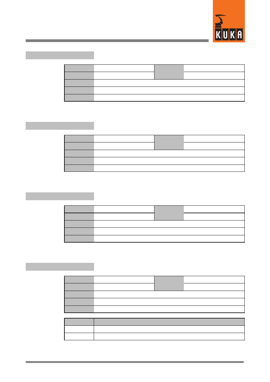
10
I (Fortsetzung)
71 of 170
SysVar 08.02.03 en
$IBS_SLAVEIN[10]
Controller input words assigned by the Interbus slave
Data type
Integer
Value
min.
Unit
Value
max.
In file
Steu\Mada\$custom.dat
Original line
INT $IBS_SLAVEIN[10]
Comments
$IBUS_OFF
Switches off alternative Interbus groups
Data type
Integer
Value
min.
Unit
Value
max.
In file
Steu\Mada\$custom.dat
Original line
INT $IBUS_OFF
Comments
$IBUS_ON
Switches on alternative Interbus groups
Data type
Integer
Value
min.
Unit
Value
max.
In file
Steu\Mada\$custom.dat
Original line
INT $IBUS_ON
Comments
$IDENT_OPT
Query whether load data determination can be carried out
Data type
Boolean
Value
min.
Unit
Value
max.
In file
Steu\Mada\$option.dat
Original line
BOOL $IDENT_OPT=FALSE
Comments
Options
Effects
TRUE
Load data determination is possible
FALSE
Load data determination is not possible
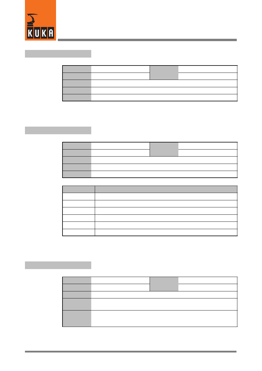
System Variables
72 of 170
SysVar 08.02.03 en
$IDENT_STARTP
Start position for load data determination
Data type
Structure
Value
min.
Unit
Value
max.
In file
R1\Mada\$operate.dat
Original line
E6AXIS $IDENT_STARTP
Comments
$IDENT_STATE
Status of load data determination
Data type
Enum
Value
min.
Unit
Value
max.
In file
Steu\Mada\$operate.dat
Original line
DECL IDENT_STATE $IDENT_STATE
Comments
Options
Effects
#I_END
Load data determination terminated
#I_READY
Ready for load data determination
#I_TEST
Test run is being carried out
#I_MEAS
Measurement is being carried out
#I_MEAS_OK Measurement was error--free
#I_CALC
Calculation is being carried out
$IN[n]
Inputs
Data type
Boolean
Value
min.
Unit
Value
max.
In file
------
Original line
BOOL $IN[4096]
;Eingang [1 bis 4096]
Comments
[n]=[1] ... [4096]
The number of inputs can be increased to max. 4096 by setting
$SET_IO_SIZE accordingly.
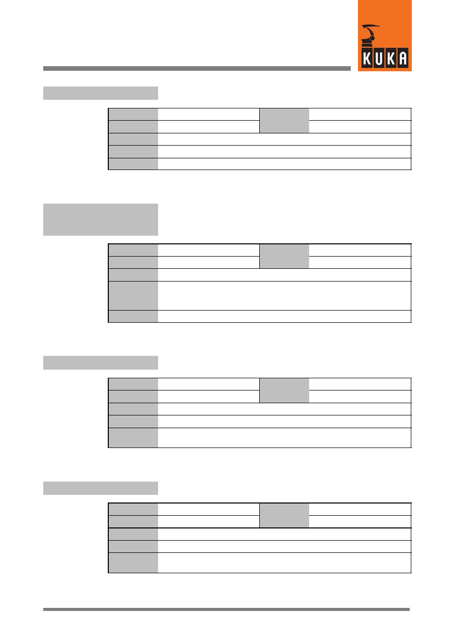
10
I (Fortsetzung)
73 of 170
SysVar 08.02.03 en
$IN_HOME
Signal declaration “Robot in home position”
Data type
Signal declaration
Value
min.
Unit
Value
max.
In file
Steu\Mada\$machine.d
Original line
SIGNAL $IN_HOME $OUT[1000]
Comments
$IN_HOME1
...
$IN_HOME5
Signal declaration “Home position1 ... 5”
Data type
Signal declaration
Value
min.
Unit
Value
max.
In file
Steu\Mada\$machine.dat
Original line
SIGNAL $IN_HOME1 $OUT[977]
...
SIGNAL $IN_HOME5 $OUT[981]
Comments
$IN_POS_MA[n]
Positioning window for following error monitoring
Data type
Real
Value
min.
Unit
mm, °
Value
max.
In file
R1\Mada\$machine.dat
Original line
REAL $IN_POS_MA[n]
Comments
[n] = [1] ... [6]:
axis A1 ... A6
[n] = [7] ... [12]: external axis E1 ... E6
$IN_STILL_MA
Factor for calculating the standstill window
Data type
Integer
Value
min.
Unit
Value
max.
In file
R1\Mada\$machine.dat
Original line
INT $IN_STILL_MA
Comments
If all axes are in position and no new setpoint is defined, the axes are
monitored to make sure they do not wander out of position.
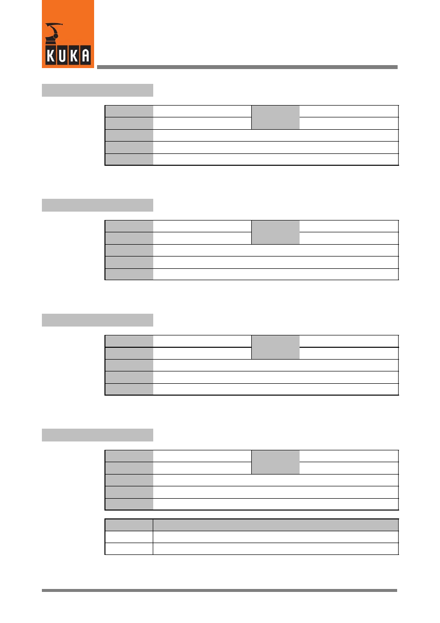
System Variables
74 of 170
SysVar 08.02.03 en
$INC_AXIS[1]...[6]
Incremental dimension, axis--specific – for axes A1 ... A6
Data type
Real
Value
min.
Unit
Value
max.
In file
R1\Mada\$machine.dat
Original line
REAL $INC_AXIS[6]
Comments
$INC_CAR[1]...[6]
Incremental dimension, Cartesian, relative to the tool, for axes A1 ... A6
Data type
Real
Value
min.
Unit
mm, °
Value
max.
In file
R1\Mada\$machine.dat
Original line
REAL $INC_CAR[6]
Comments
$INC_EXTAX
Incremental dimension (axis--specific) for external axes
Data type
Real
Value
min.
Unit
mm, °
Value
max.
In file
R1\Mada\$machine.dat
Original line
REAL $INC_EXTAX[6]
Comments
$INPOSITION
Bit array for “Axis in position” of all axes, A1 ... A6, E1 ... E6
Data type
Integer
Value
min.
Unit
Value
max.
In file
------
Original line
INT $INPOSITION
Comments
Options
Effects
Bit=0
Axis in motion
Bit=1
Axis in positioning window
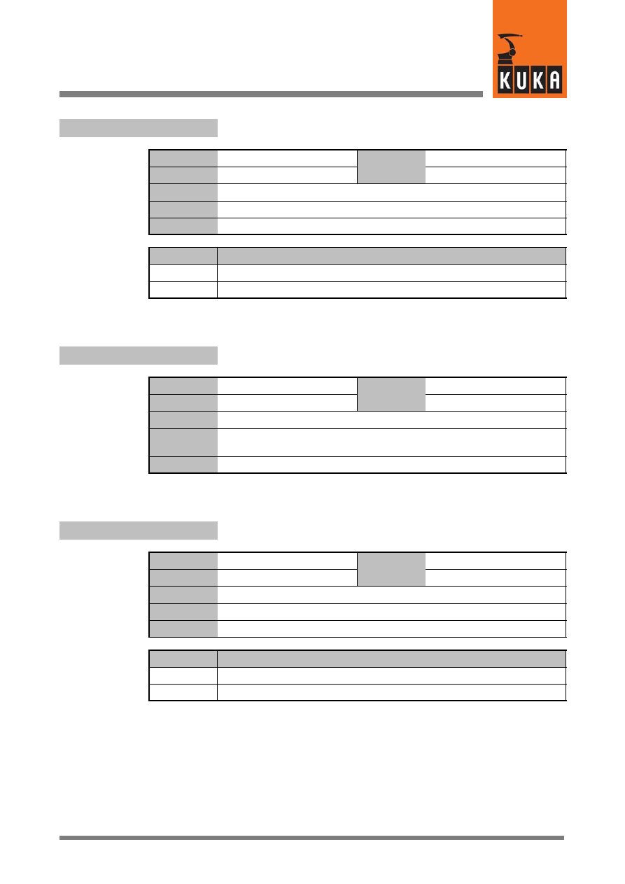
10
I (Fortsetzung)
75 of 170
SysVar 08.02.03 en
$INTERPRETER
Selection of the Submit or robot interpreter
Data type
Integer
Value
min.
Unit
Value
max.
In file
------
Original line
INT $INTERPRETER
Comments
Options
Effects
0
Submit interpreter
1
Robot interpreter
$INTERRUPT
Program is processing an interrupt
Data type
Boolean
Value
min.
Unit
Value
max.
In file
R1\Mada\$operate.dat
Original line
BOOL $INTERRUPT
;Interruptbearbeitung
Comments
$IOSIM_OPT
Simulation of inputs/outputs
Data type
Boolean
Value
min.
Unit
Value
max.
In file
------
Original line
BOOL $IOSIM_OPT
Comments
Options
Effects
TRUE
I/O simulation activated
FALSE
I/O simulation deactivated
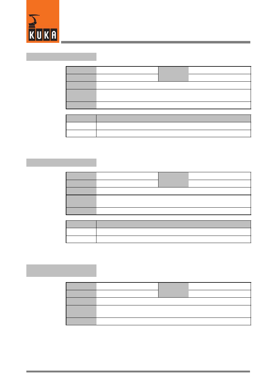
System Variables
76 of 170
SysVar 08.02.03 en
$IPO_MODE
Advance run interpolation mode
Data type
Enum
Value
min.
Unit
Value
max.
In file
------
Original line
DECL IPO_MODE $IPO_MODE
;Interpolationsart Vorlauf
Comments
Options
Effects
#BASE
#TCP
$IPO_MODE_C
Main run interpolation mode
Data type
Enum
Value
min.
Unit
Value
max.
In file
Original line
DECL IPO_MODE $IPO_MODE_C
;Interpolationsart Hauptlauf
Comments
Options
Effects
#BASE
#TCP
$ITER
Number of iterations for path planning with activated acceleration
adaptation and higher motion profile
Data type
Integer
Value
min.
Unit
Value
max.
In file
R1\Mada\$robcor.dat
Original line
INT $ITER
;Anzahl der Iterationen
Comments

11
J
77 of 170
SysVar 08.02.03 en
11
J
$JUS_TOOL_NO
Number of the current tool for EMT mastering
Data type
Integer
Value
min.
Unit
Value
max.
In file
Steu\Mada\$operate.dat
Original line
INT $JUS_TOOL_NO
Comments
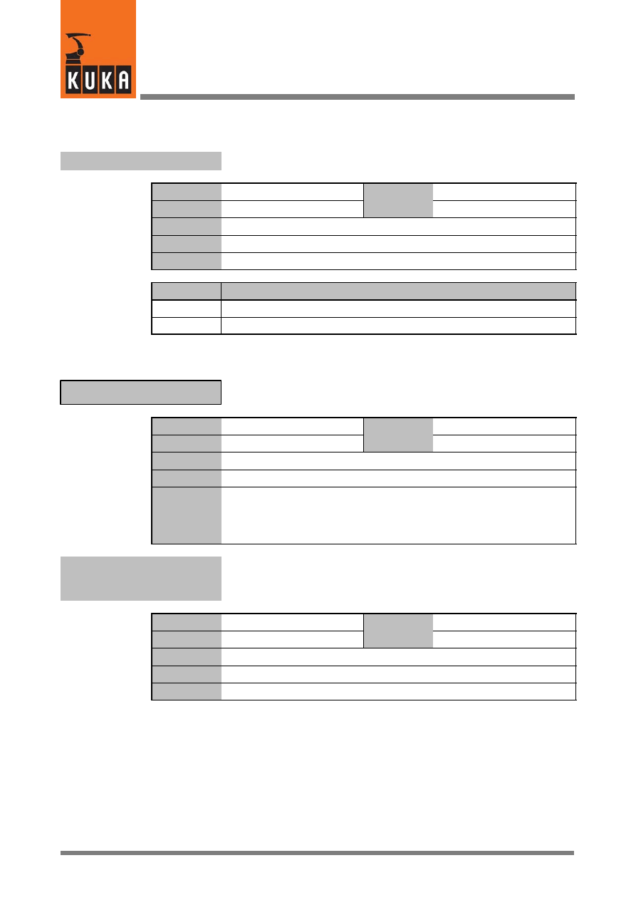
System Variables
78 of 170
SysVar 08.02.03 en
12
K
$KCP_CONNECT
Display whether the KCP is connected to the controller
Data type
Boolean
Value
min.
Unit
Value
max.
In file
------
Original line
BOOL $KCP_CONNECT
Comments
Options
Effects
TRUE
KCP is connected
FALSE
KCP is not connected
Assignment of jog keys to axes
$KEYMOVE
Data type
Structure
Value
min.
Unit
Value
max.
In file
------
Original line
DECL KEYMOVE $KEYMOVE
Comments
These six fields (T1 to T6) are used to store which axis is moved using which
of the corresponding plus--minus rockers.
Whether or not the jog keys are active depends on the state of the system
variable $KEYMOVE.
$KEYMOVE.T1
...
$KEYMOVE.T6
Status of plus/minus key 1 ... 6 (from top on the KCP)
Data type
Integer
Value
min.
Unit
Value
max.
In file
------
Original line
STRUC KEYMOVE INT T1,T2,T3,T4,T5,T6
Comments
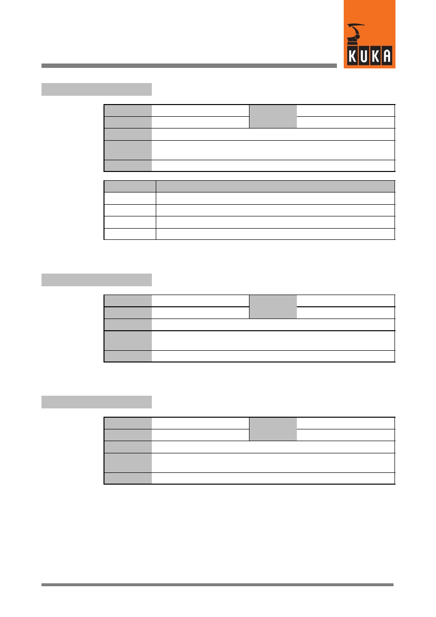
12
K (Fortsetzung)
79 of 170
SysVar 08.02.03 en
$KINCLASS
Kinematic classes
Data type
Enum
Value
min.
Unit
Value
max.
In file
R1\Mada\$machine.dat
Original line
DECL KINCLASS $KINCLASS=#STANDARD
;Kinematikklassen (STANDARD,SPECIAL,TEST,NONE)
Comments
Options
Effects
#STANDARD
#SPECIAL
#TEST
#NONE
$KPS_CURR_MAX[8]
Maximum current of a KPS over 1 second
Data type
Real
Value
min.
Unit
Value
max.
In file
R1\Mada\$machine.dat
Original line
REAL $KPS_CURR_MAX[8]
;Maximalstrom eines KPS über 1 s
Comments
KPS = KUKA Power Supply
$KPS_CURR_RATED[8]
Rated current of KPS for a duration of 60 seconds
Data type
Real
Value
min.
Unit
Value
max.
In file
R1\Mada\$machine.dat
Original line
REAL $KPS_CURR_RATED[8]
;Nennstrom eines KPS über 60 s
Comments
KPS = KUKA Power Supply
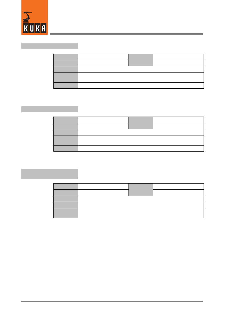
System Variables
80 of 170
SysVar 08.02.03 en
$KR_SERIALNO
Serial number of the robot
Data type
Integer
Value
min.
Unit
Value
max.
In file
------
Original line
INT $KR_SERIALNO
;Roboter--Seriennummer
Comments
$KT_MOT
KT factor of motors (relationship between current and torque)
Data type
Real
Value
min.
Unit
Value
max.
In file
R1\Mada\$machine.dat
Original line
REAL $KT_MOT[12]
;KT--Faktor der Motoren
Comments
$KT0_MOT[n]
KT0 factor of servomotors
(defined at working point with speed=0)
Data type
Real
Value
min.
Unit
Value
max.
In file
R1\Mada\$machine.dat
Original line
REAL $KT0_MOT[n]
Comments
[n] = [1] ... [6]:
axis A1 ... A6
[n] = [7] ... [12]: external axis E1 ... E6
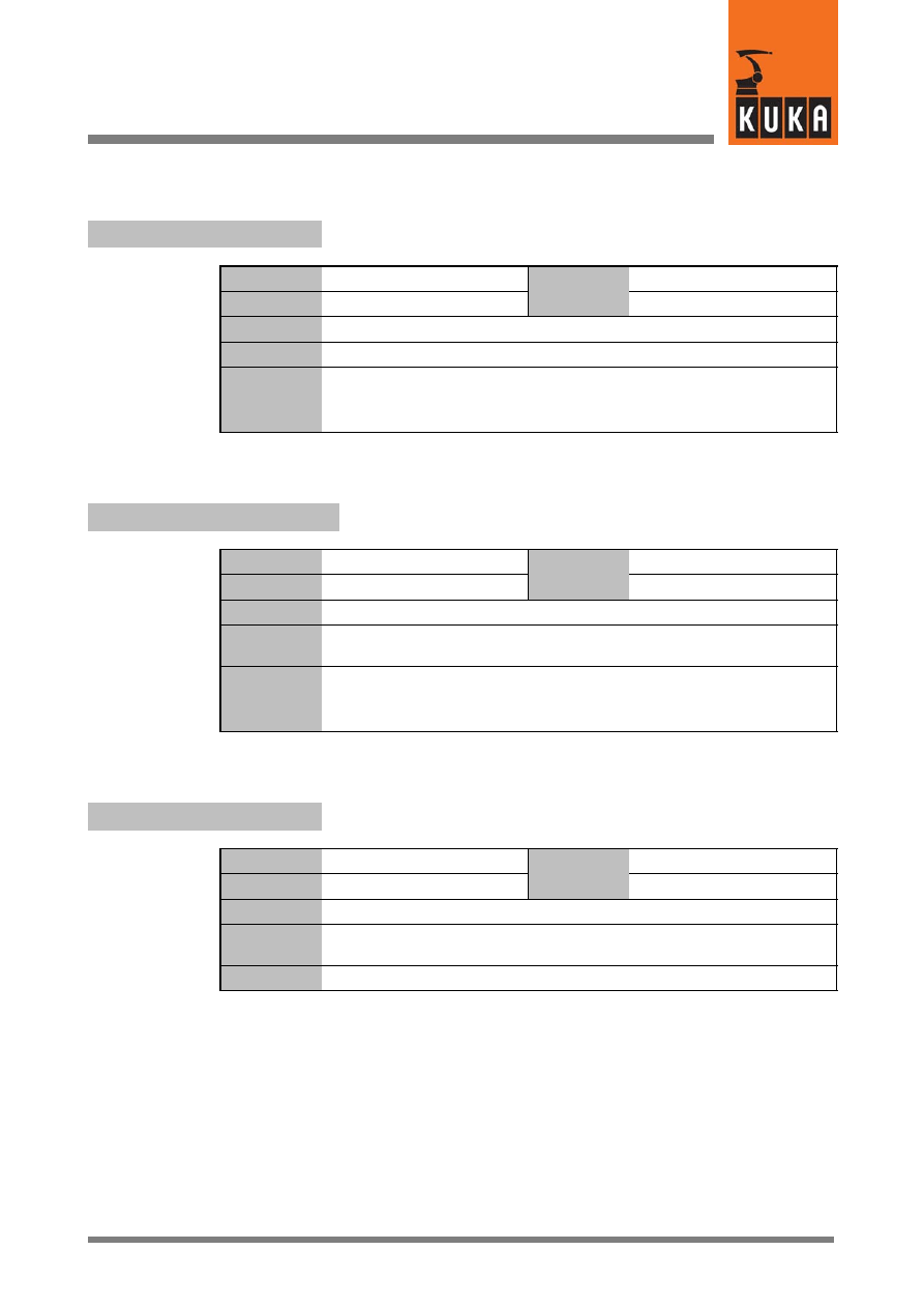
13
L
81 of 170
SysVar 08.02.03 en
13
L
$L_EMT_MAX[n]
Maximum length of EMT mastering travel
Data type
Real
Value
min.
Unit
mm, °
Value
max.
In file
R1\Mada\$machine.dat
Original line
REAL $L_EMT_MAX[n]
Comments
[n] = [1] ... [6]:
axis A1 ... A6
[n] = [7] ... [12]: external axis E1 ... E6
If the travel length is exceeded, an error message will be displayed.
$LAST_BUFFERING_NOTOK
Signal declaration “Battery message”
Data type
Signal declaration
Value
min.
Unit
Value
max.
In file
Steu\Mada\$machine.dat
Original line
SIGNAL $LAST_BUFFERING_NOTOK $OUT[1003]
;Ausgang signalisiert eine anstehende Akkumeldung
Comments
If the variable “$LAST_BUFFERING_NOTOK” has the value “TRUE”,
the battery voltage was too low the last time the system was shut down.
Otherwise, the value is “FALSE”.
$LENGTH_A
Main axis length A, eccentricity of axis 2 relative to axis 1
Data type
Real
Value
min.
Unit
Value
max.
In file
R1\Mada\$machine.dat
Original line
REAL $LENGTH_A
;Grundachslaenge A
Comments

System Variables
82 of 170
SysVar 08.02.03 en
$LENGTH_B
Main axis length B, link arm length
Data type
Real
Value
min.
Unit
Value
max.
In file
R1\Mada\$machine.dat
Original line
REAL $LENGTH_B
;Grundachslaenge B
Comments
$LG_CP
Proportional gain of the position controller for CP motion
Data type
Real
Value
min.
Unit
1/ms
Value
max.
In file
R1\Mada\$machine.dat
Original line
REAL $LG_CP[12]
;KV--Faktor Bahn--fahren [1/ms]
Comments
$LG_PTP
Proportional gain of the position controller for PTP motion
Data type
Real
Value
min.
Unit
1/ms
Value
max.
In file
R1\Mada\$machine.dat
Original line
REAL $LG_PTP[12]
;KV--Faktor PTP Achse [I] (i=1:A1,i=7:E1) [1/ms]
Comments
$LINE_SEL_OK
Display whether block selection was successful
Data type
Boolean
Value
min.
Unit
Value
max.
In file
------
Original line
BOOL $LINE_SEL_OK
Comments
Options
Effects
TRUE
Block selection took place
FALSE
Block selection did not take place
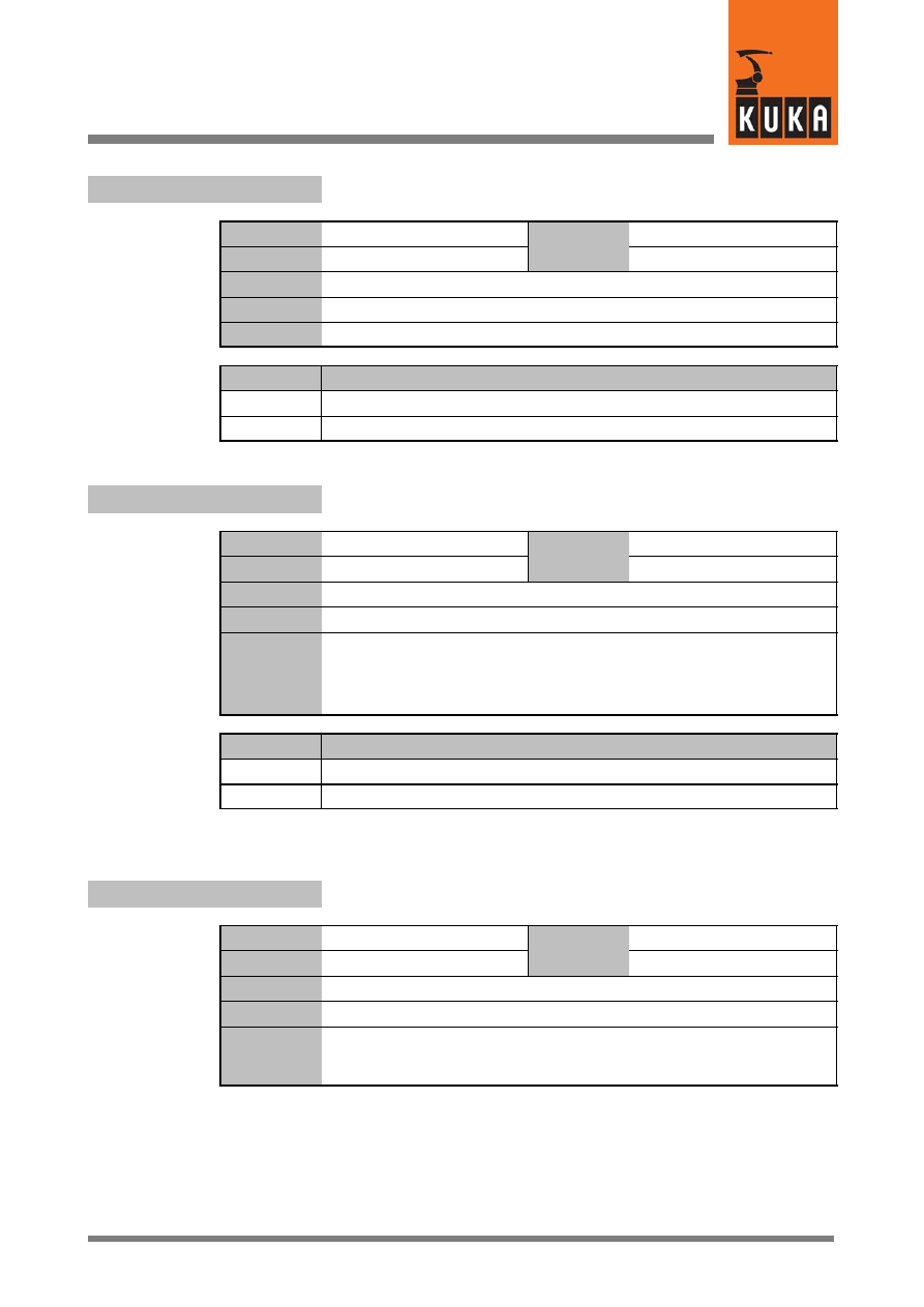
13
L (Fortsetzung)
83 of 170
SysVar 08.02.03 en
$LINE_SELECT
Editing with or without implicit block selection
Data type
Boolean
Value
min.
Unit
Value
max.
In file
------
Original line
BOOL $LINE_SELECT
Comments
Options
Effects
TRUE
Editing with block selection
FALSE
Editing without block selection
$LOOP_CONT
Results of simulation for loop termination condition
Data type
Boolean
Value
min.
Unit
Value
max.
In file
------
Original line
BOOL $LOOP_CONT=FALSE
Comments
Simulation result which can be used as loop termination condition.
$LOOP_CONT receives the value FALSE as soon as the simulation key is
pressed. The value must be set to TRUE before using $LOOP_MSG to start
a simulation.
Options
Effects
TRUE
Simulation key pressed
FALSE
Simulation key not pressed
$LOOP_MSG
Start simulation if value not equal to blank string
Data type
Character
Value
min.
Unit
Value
max.
In file
Steu\Mada\$option.dat
Original line
CHAR $LOOP_MSG[128]
Comments
Starts the simulation as soon as the value is not equal to blank string, and
causes the text contained and the simulation key to be displayed.
To end the simulation, the value must be reset to blank string.

System Variables
84 of 170
SysVar 08.02.03 en
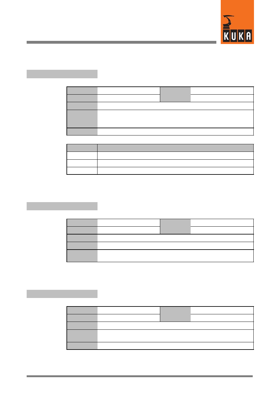
14
M
85 of 170
SysVar 08.02.03 en
14
M
$MAIN_AXIS
Main axis identification
Data type
Enum
Value
min.
Unit
Value
max.
In file
R1\Mada\$machine.dat
Original line
DECL MAIN_AXIS $MAIN_AXIS=#NR
;Grundachsenkennung
(SS = Portal, CC = Scara, NR = Gelenkroboter)
Comments
Options
Effect
#SS
Gantry robot
#CC
SCARA robot
#NR
Jointed--arm robot
$MAMES[n]
Offset between mechanical and mathematical zero of axis n
Data type
Real
Value
min.
Unit
mm, °
Value
max.
In file
R1\Mada\$machine.dat
Original line
REAL $MAMES[n]
Comments
[n] = [1] ... [6]:
axis A1 ... A6
[n] = [7] ... [12]: external axis E1 ... E6
$MEAS_PULSE
Activate rapid gauging
Data type
Boolean
Value
min.
Unit
Value
max.
In file
------
Original line
BOOL $MEAS_PULSE[5]
;Messpuls
Comments

System Variables
86 of 170
SysVar 08.02.03 en
$MODE_MOVE
Motion type in jog mode
Data type
Enum
Value
min.
Unit
Value
max.
In file
------
Original line
DECL MODE_MOVE $MODE_MOVE
Comments
Options
Effect
#MM
Jogging
#MC
Manual referencing
#MI
Incremental motion
$MODE_OP
Display current operating mode
Data type
Enum
Value
min.
Unit
Value
max.
In file
------
Original line
DECL MODE_OP $MODE_OP
;Betriebsart (T1, T2, AUT, EX)
Comments
Options
Effect
#T1
Test 1
#T2
Test 2
#AUT
Automatic
#EX
Automatic External
$MODEL_NAME
Robot type
Data type
Character
Value
min.
Unit
Value
max.
In file
R1\Mada\$robcor.dat
Original line
CHAR $MODEL_NAME[32]
Comments
Defines the robot type.
14
M (Fortsetzung)
87 of 170
SysVar 08.02.03 en
$MOUSE_ACT
Status of the Space Mouse
Data type
Boolean
Value
min.
Unit
Value
max.
In file
------
Original line
BOOL $MOUSE_ACT
Comments
Options
Effect
TRUE
Space Mouse active
FALSE
Space Mouse not active
$MOUSE_DOM
Mode for Space Mouse
Dominant coordinate / All coordinates
Data type
Boolean
Value
min.
Unit
Value
max.
In file
------
Original line
BOOL $MOUSE_DOM
Comments
Options
Effect
TRUE
Space Mouse in mode “Dominant coordinate active”
FALSE
Space Mouse in mode “All coordinates active”
$MOUSE_ROT
Space Mouse – set rotational motions to active
Data type
Boolean
Value
min.
Unit
Value
max.
In file
------
Original line
BOOL $MOUSE_ROT
Comments
Options
Effect
TRUE
Space Mouse “rotational” motions switched on
FALSE
Space Mouse “rotational” motions switched off
System Variables
88 of 170
SysVar 08.02.03 en
$MOUSE_TRA
Space Mouse – set translational motions to active
Data type
Boolean
Value
min.
Unit
Value
max.
In file
------
Original line
BOOL $MOUSE_TRA
Comments
Options
Effect
TRUE
Space Mouse “translational” motions switched on
FALSE
Space Mouse “translational” motions switched off
$MOVE_BCO
Block coincidence run (BCO)
Data type
Boolean
Value
min.
Unit
Value
max.
In file
------
Original line
BOOL $MOVE_BCO
;Aktuelle Bewegung ist SAK--Fahrt
Comments
Options
Effect
TRUE
Current motion is BCO run
FALSE
No BCO run
$MOVE_ENABLE
Signal declaration “Move enable”
Data type
Signal declaration
Value
min.
Unit
Value
max.
In file
Steu\Mada\$machine.dat
Original line
SIGNAL $MOVE_ENABLE $IN[1025]
;Fahrfreigabe gesamt
Comments

14
M (Fortsetzung)
89 of 170
SysVar 08.02.03 en
$MOVE_ENA_ACK
Move enable signal feedback signal
Data type
Signal declaration
Value
min.
Unit
Value
max.
In file
Steu\Mada\$machine.dat
Original line
SIGNAL $MOVE_ENA_ACK $OUT[150]
;Rueckmeldung $MOVE_ENABLE an PLC
Comments
$MOVE_STATE
Current status of motion
Data type
Enum
Value
min.
Unit
Value
max.
In file
------
Original line
DECL MOVE_STATE $MOVE_STATE
Comments
$MOVE_STATE is used in path planning to identify the individual motion
path sections.
In the case of RESET, CANCEL, block selection and no program selected,
$MOVE_STATE has the value #NONE.
$MOVE_STATE is composed of two parts. The first is the designation of the
specific type of motion (PTP, LIN, CIRC), and the second is the identifier of
the current section of the path.
#xxx_SINGLE designates a motion outside an approximate positioning
range;
#xxx_APO1 designates a motion inside an approximate positioning range
up to the middle of the block;
#xxx_APO2 designates a motion inside an approximate positioning range
after the middle of the block;
#NONE designates the state with no program selected, in the case of
RESET or CANCEL.
$MS_DA[n]
Status of position control monitoring
Data type
Integer
Value
min.
Unit
Value
max.
In file
R1\Mada\$machine.dat
Original line
INT $MS_DA[n]
Comments
[n] = [1] ... [6]:
axis A1 ... A6
[n] = [7] ... [12]: external axis E1 ... E6
System Variables
90 of 170
SysVar 08.02.03 en
Structure for message display
$MSG_T
Data type
Structure
Value
min.
Unit
Value
max.
In file
Steu\Mada\$option.dat
Original line
DECL MSG_T $MSG_T={VALID FALSE,RELEASE FALSE,TYP
#NOTIFY,MODUL[] ” ”,KEY[] ” ”,PARAM_TYP #VALUE,PARAM[] ”
”,DLG_FORMAT[] ” ”,ANSWER 0}
Comments
$MSG_T.ANSWER
Number of the softkey pressed
Data type
Integer
Value
min.
Unit
Value
max.
$MSG_T.DLG_FORMAT
Label of the softkeys
Data type
Character
Value
min.
Unit
Value
max.
$MSG_T.KEY
Key to the message text in the data bank
$MSG_T.MODUL
Module identifier for access to database
$MSG_T.PARAM
Additional parameter displayed with the message text
$MSG_T.PARAM_TYP
“PARAM” type definition
Data type
Enum
Value
min.
Unit
Value
max.
Options
Effect
#VALUE
#WORDS
#KEY
$MSG_T.RELEASE
Deletion of status message
Data type
Boolean
Value
min.
Unit
Value
max.
14
M (Fortsetzung)
91 of 170
SysVar 08.02.03 en
$MSG_T.TYP
Definition of message type
Data type
Enum
Value
min.
Unit
Value
max.
Options
Effect
#NOTIFY
Notification message
#STATE
Status message
#QUIT
Acknowledgment message
#DIALOG
Dialog query
$MSG_T.VALID
Output of message text
Data type
Boolean
Value
min.
Unit
Value
max.
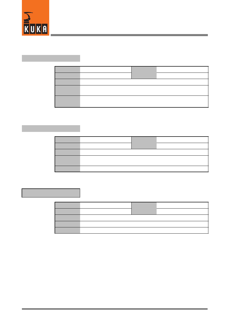
System Variables
92 of 170
SysVar 08.02.03 en
15
N
$NEAR_POSRET
Robot is within a sphere about “$POS_RET” (tolerance window)
Data type
Signal declaration
Value
min.
Unit
Value
max.
In file
Steu\Mada\$machine.dat
Original line
SIGNAL $NEAR_POSRET $OUT[997]
;Roboter in Toleranzfenster
Comments
Signal is set if the robot is positioned within a sphere about $POS_RET.
The radius of this sphere is defined in $NEARPATHTOL.
$NEARPATHTOL
Radius of the sphere about “$POS_RET”
Data type
Real
Value
min.
Unit
Value
max.
In file
Steu\Mada\$custom.dat
Original line
REAL $NEARPATHTOL
;Toleranz für die Abweichung von $POS_RET
Comments
Null frame
$NULLFRAME
Data type
Structure
Value
min.
Unit
Value
max.
In file
------
Original line
FRAME $NULLFRAME
Comments
All values for offset (X, Y, Z) and rotation (A, B, C) are set to zero.
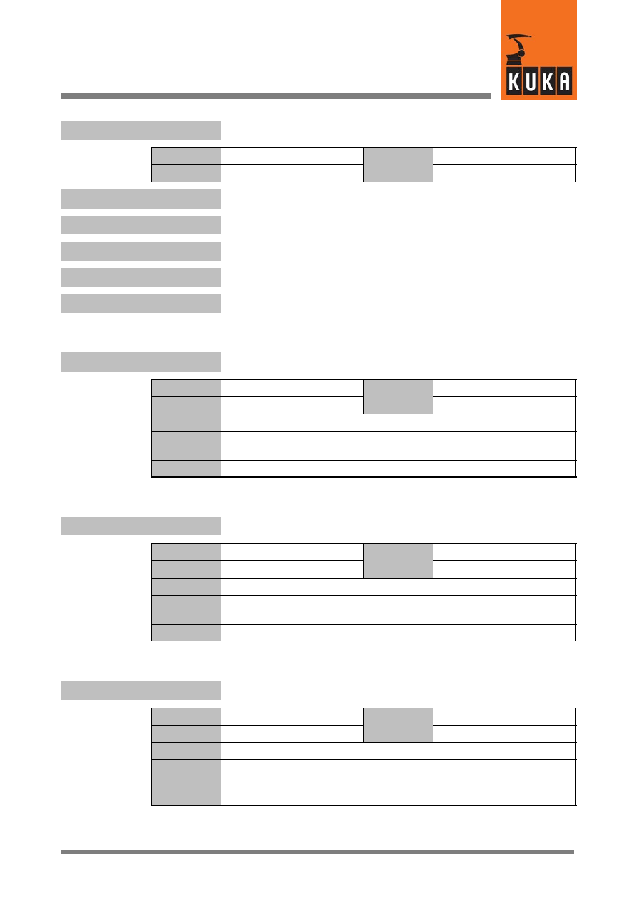
15
N (Fortsetzung)
93 of 170
SysVar 08.02.03 en
$NULLFRAME.A
Rotation about the Z axis
Data type
Real
Value
min.
Unit
mm, °
Value
max.
$NULLFRAME.B
Rotation about the Y axis
$NULLFRAME.C
Rotation about the X axis
$NULLFRAME.X
Offset in the X direction
$NULLFRAME.Y
Offset in the Y direction
$NULLFRAME.Z
Offset in the Z direction
$NUM_AX
Number of robot axes
Data type
Integer
Value
min.
Unit
Value
max.
In file
R1\Mada\$machine.dat
Original line
INT $NUM_AX=6
;Achsen des Robotersystems
Comments
$NUM_IN
Maximum number of digital inputs ($IN)
Data type
Integer
Value
min.
Unit
Value
max.
In file
------
Original line
INT $NUM_IN
;Anzahl der Eingaenge
Comments
$NUM_OUT
Maximum number of digital outputs ($OUT)
Data type
Integer
Value
min.
Unit
Value
max.
In file
------
Original line
INT $NUM_OUT
;Anzahl der Ausgaenge
Comments

System Variables
94 of 170
SysVar 08.02.03 en
$NUMSTATE
State of the Num Lock key
Data type
Boolean
Value
min.
Unit
Value
max.
In file
------
Original line
BOOL $NUMSTATE
Comments
Options
Effect
TRUE
Num Lock key on
FALSE
Num Lock key off
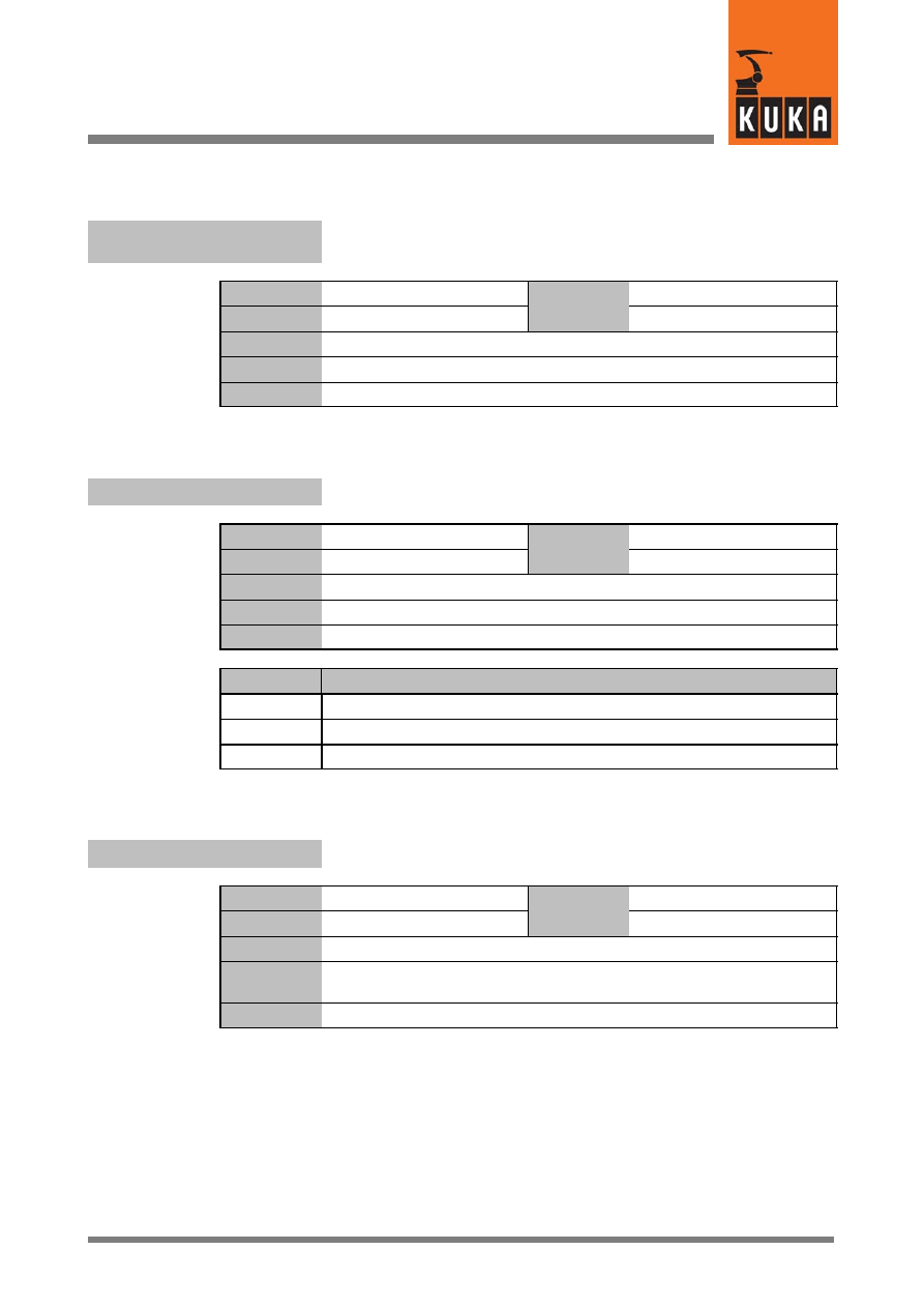
16
O
95 of 170
SysVar 08.02.03 en
16
O
$ON_PATH
Signal declaration “Path check” –
robot is on the programmed path
Data type
Signal declaration
Value
min.
Unit
Value
max.
In file
Steu\Mada\$machine.dat
Original line
SIGNAL $ON_PATH $OUT[997]
Comments
$OPT_MOVE
Activation of the higher motion profile
Data type
Enum
Value
min.
Unit
Value
max.
In file
R1\Mada\$robcor.dat
Original line
DECL ADAP_ACC $OPT_MOVE=#NONE
Comments
Options
Effect
#NONE
Higher motion profile deactivated
#STEP1
Higher motion profile without energy planning activated
#STEP2
Higher motion profile with energy planning activated
$OPT_VAR_IDX
Index of selected correction variables from the list “$OPT_VAR[]”
Data type
Integer
Value
min.
Unit
Value
max.
In file
------
Original line
INT $OPT_VAR_IDX
;Index Korr.--Var. in der Var.--Liste $OPT_VAR[]
Comments
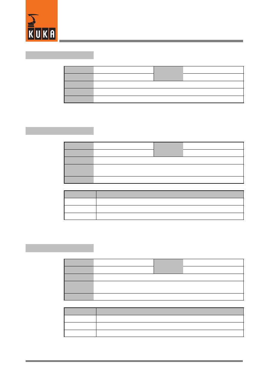
System Variables
96 of 170
SysVar 08.02.03 en
$ORI_CHECK
Orientation check at CP end points (only with five--axis robots)
Data type
Integer
Value
min.
Unit
Value
max.
In file
R1\Mada\$machine.dat
Original line
INT $ORI_CHECK
Comments
$ORI_TYPE
Orientation control for CP instructions (LIN, CIRC) in the advance run
Data type
Enum
Value
min.
Unit
Value
max.
In file
------
Original line
DECL ORI_TYPE $ORI_TYPE
;Orientierungsfuehrung bei CP--Saetzen (Vorlauf)
Comments
Options
Effect
#VAR
Variable orientation with possible reduction of velocity and acceleration
#CONSTANT Constant orientation
#JOINT
Variable orientation without reduction of velocity and acceleration
$ORI_TYPE_C
Orientation control for CP instructions (LIN, CIRC) in the main run
Data type
Enum
Value
min.
Unit
Value
max.
In file
------
Original line
DECL ORI_TYPE $ORI_TYPE_C
;Orientierungsfuehrung bei CP--Saetzen (Hauptlauf)
Comments
Options
Effect
#VAR
Variable orientation with possible reduction of velocity and acceleration
#CONSTANT Constant orientation
#JOINT
Variable orientation without reduction of velocity and acceleration
16
O (Fortsetzung)
97 of 170
SysVar 08.02.03 en
$OUT[n]
Outputs
Data type
Boolean
Value
min. 1
Unit
Value
max. 4096
In file
------
Original line
BOOL $OUT[4096]
;Ausgang [1 bis 4096] )*
Comments
[n] = [1] ... [4096]
)* 1024, 2048 or 4096 outputs can be set by setting the variable
“$SET_IO_SIZE” accordingly.
$OUT_C[n]
Outputs
Data type
Boolean
Value
min.
1
Unit
Value
max.
4096
In file
------
Original line
BOOL $OUT_C[4096]
;Ausgang [1 bis 4096] )*
Comments
[n] = [1] ... [4096]
For setting outputs at the end point for motions with exact positioning and
at the vertex for approximate positioning motions.
)* 1024, 2048 or 4096 outputs can be set by setting the variable
“$SET_IO_SIZE” accordingly.
$OV_ASYNC
Override for asynchronous external axes
Data type
Integer
Value
min.
0
Unit
%
Value
max.
100
In file
------
Original line
INT $OV_ASYNC
;OVERRIDE asynchrone Zusatzachsen
Comments
System Variables
98 of 170
SysVar 08.02.03 en
$OV_JOG
Jog override
Data type
Integer
Value
min.
0
Unit
%
Value
max.
100
In file
------
Original line
INT $OV_JOG
;Einricht--OVERRIDE
Comments
$OV_PRO
Program override
Data type
Integer
Value
min.
0
Unit
%
Value
max.
100
In file
------
Original line
INT $OV_PRO
Comments
$OV_PRO1
Internal use in the controller
Data type
Integer
Value
min.
Unit
Value
max.
In file
------
Original line
INT $OV_PRO1
Comments
$OV_ROB
Robot override
Data type
Integer
Value
min.
Unit
%
Value
max.
In file
------
Original line
INT $OV_ROB
Comments

16
O (Fortsetzung)
99 of 170
SysVar 08.02.03 en
$OV_ROB1
Internal use in the controller
Data type
Integer
Value
min.
Unit
Value
max.
In file
------
Original line
INT $OV_ROB1
Comments
System Variables
100 of 170
SysVar 08.02.03 en
17
P
$PAL_MODE
Activate palletizing mode
Data type
Boolean
Value
min.
Unit
Value
max.
In file
------
Original line
BOOL $PAL_MODE
;Achse A4 wird auf null Grad fixiert
Comments
Axis 4 is fixed at 0°.
$PAL_MODE = $DEF_A4FIX is set during loading and program reset.
Palletizing mode is automatically activated for a 5--axis robot and not for
a normal 6--axis robot.
Options
Effect
TRUE
Palletizing mode on
FALSE
Palletizing mode off
$PERI_RDY
Signal declaration “Drives ON”
Data type
Signal declaration
Value
min.
Unit
Value
max.
In file
Steu\Mada\$machine.dat
Original line
SIGNAL $PERI_RDY $OUT[1012]
Comments
$PHGBRIGHT
Set display brightness
Data type
Integer
Value
min.
0
Unit
Value
max.
15
In file
------
Original line
INT $PHGBRIGHT
Comments
The value set is lost if the robot controller is switched off
Options
Effect
0
Display is dark
15
Display is bright
17
P (Fortsetzung)
101 of 170
SysVar 08.02.03 en
$PHGCONT
Set display contrast
Data type
Integer
Value
min. 0
Unit
Value
max. 15
In file
------
Original line
INT $PHGCONT
Comments
The value set is lost if the robot controller is switched off
Options
Effect
0
Lower contrast, dark
15
Higher contrast, bright
$PHGINFO
Serial number of the KCP CPU and software version
Data type
Character
Value
min.
Unit
Value
max.
In file
------
Original line
CHAR $PHGINFO[24]
Comments
$PHGTEMP
Current temperature inside the KCP
Data type
Integer
Value
min.
Unit
°C
Value
max.
In file
------
Original line
INT $PHGTEMP
Comments
$PMCHANNEL[n]
Assignment of the axes to the drive interfaces in the power module
Data type
Integer
Value
min.
Unit
Value
max.
In file
R1\Mada\$machine.dat
Original line
INT $PMCHANNEL[n]
;Antriebsschnittstellen--Nr. auf dem Powermodul
Comments
[n] = [1] ... [6]: axis A1 ... A6
[n] = [7] ... [12]: external axis E1 ... E6
System Variables
102 of 170
SysVar 08.02.03 en
Current robot position, Cartesian
$POS_ACT
Data type
Structure
Value
min.
Unit
mm, °
Value
max.
In file
------
Original line
E6POS $POS_ACT
;Aktuelle Roboterposition kartesisch [mm,Grad]
Comments
$POS_ACT.A
Rotation about the Z axis
Data type
Real
Value
min.
Unit
mm, °
Value
max.
$POS_ACT.B
Rotation about the Y axis
$POS_ACT.C
Rotation about the X axis
$POS_ACT.X
Offset in the X direction
$POS_ACT.Y
Offset in the Y direction
$POS_ACT.Z
Offset in the Z direction
$POS_ACT_MES
Measured actual position, Cartesian
Data type
Structure
Value
min.
Unit
Value
max.
In file
------
Original line
E6POS $POS_ACT_MES
Comments

17
P (Fortsetzung)
103 of 170
SysVar 08.02.03 en
Start position of the current motion block, Cartesian
$POS_BACK
Data type
Structure
Value
min.
Unit
mm, °
Value
max.
In file
------
Original line
E6POS $POS_BACK
;Anfangsposition des aktuellen Bewegungssatzes kartesisch [mm,Grad]
Comments
$POS_BACK.A
Rotation about the Z axis
Data type
Real
Value
min.
Unit
°
Value
max.
$POS_BACK.B
Rotation about the Y axis
$POS_BACK.C
Rotation about the X axis
$POS_BACK.X
Offset in the X direction
Data type
Real
Value
min.
Unit
mm
Value
max.
$POS_BACK.Y
Offset in the Y direction
$POS_BACK.Z
Offset in the Z direction
System Variables
104 of 170
SysVar 08.02.03 en
Target position of the current motion block, Cartesian
$POS_FOR
Data type
Structure
Value
min.
Unit
mm, °
Value
max.
In file
------
Original line
E6POS $POS_FOR
;Zielposition des aktuellen Bewegungssatzes kartesisch [mm,Grad]
Comments
$POS_FOR.A
Rotation about the Z axis
Data type
Real
Value
min.
Unit
°
Value
max.
$POS_FOR.B
Rotation about the Y axis
$POS_FOR.C
Rotation about the X axis
$POS_FOR.X
Offset in the X direction
$POS_FOR.Y
Offset in the Y direction
$POS_FOR.Z
Offset in the Z direction
17
P (Fortsetzung)
105 of 170
SysVar 08.02.03 en
Position when interrupt is triggered, Cartesian
$POS_INT
Data type
Structure
Value
min.
Unit
mm, °
Value
max.
In file
------
Original line
E6POS $POS_INT
;Unterbrechungsposition kartesisch [mm,Grad]
Comments
$POS_INT.A
Rotation about the Z axis
Data type
Real
Value
min.
Unit
°
Value
max.
$POS_INT.B
Rotation about the Y axis
$POS_INT.C
Rotation about the X axis
$POS_INT.X
Offset in the X direction
Data type
Real
Value
min.
Unit
mm
Value
max.
$POS_INT.Y
Offset in the Y direction
$POS_INT.Z
Offset in the Z direction
System Variables
106 of 170
SysVar 08.02.03 en
Position when leaving the path, Cartesian
$POS_RET
Data type
Structure
Value
min.
Unit
mm, °
Value
max.
In file
------
Original line
E6POS $POS_RET
;Rückpositionieren kartesisch [mm,Grad]
Comments
$POS_RET.A
Rotation about the Z axis
Data type
Real
Value
min.
Unit
°
Value
max.
$POS_RET.B
Rotation about the Y axis
$POS_RET.C
Rotation about the X axis
$POS_RET.X
Offset in the X direction
Data type
Real
Value
min.
Unit
mm
Value
max.
$POS_RET.Y
Offset in the Y direction
$POS_RET.Z
Offset in the Z direction
$POWER_FAIL
Display of power failure
Data type
Boolean
Value
min.
Unit
Value
max.
In file
------
Original line
BOOL $POWER_FAIL
Comments
Options
Effect
TRUE
Power failure
FALSE
No power failure
17
P (Fortsetzung)
107 of 170
SysVar 08.02.03 en
Internal register of power module 1 ... 4 for diagnostic purposes
$POWERMODUL1
...
$POWERMODUL4
Data type
Structure
Value
min.
Unit
Value
max.
In file
------
Original line
DECL POWERMODUL $POWERMODUL1
...
DECL POWERMODUL $POWERMODUL4
Comments
$POWERMODUL1.BUSVOLTAGE
...
$POWERMODUL4.BUSVOLTAGE
Intermediate circuit voltage, power module 1 ... 4
Data type
Integer
Value
min.
Unit
Value
max.
$POWERMODUL1.CURRCAL
...
$POWERMODUL4.CURRCAL
Current calibration, power module 1 ... 4
$POWERMODUL1.CURRERROR
...
$POWERMODUL4.CURRERROR
Current error, power module 1 ... 4
$POWERMODUL1.PMERROR
...
$POWERMODUL4.PMERROR
Register for error messages, power module 1 ... 4
$POWERMODUL1.PMSTATE
...
$POWERMODUL4.PMSTATE
State of power module 1 ... 4
System Variables
108 of 170
SysVar 08.02.03 en
$POWEROFF_DELAYTIME
Wait time before shutting down the system
Data type
Real
Value
min.
0
Unit
s
Value
max.
30000
In file
------
Original line
INT $POWEROFF_DELAYTIME
Comments
Options
Effect
0
The controller is shut down despite external power supply.
1...30000
Wait time in seconds before the system is shut down.
NOTE
On controllers of type KR C3A, KR C3E or COBRA, the variable $POWEROFF_DE-
LAYTIME may be set to no more than 180 s. Otherwise, there is a risk of data loss.
$PR_MODE
Signal declaration “Test mode”
Data type
Signal declaration
Value
min.
Unit
Value
max.
In file
Steu\Mada\$machine.dat
Original line
SIGNAL $PR_MODE $OUT[998]
Comments
$PRO_ACT
Signal declaration “Program status”
Data type
Signal declaration
Value
min.
Unit
Value
max.
In file
R1\Mada\$machine.dat
Original line
SIGNAL $PRO_ACT $OUT[1021]
Comments
Options
Effect
TRUE
Process is active.
FALSE
Process is not active.
17
P (Fortsetzung)
109 of 170
SysVar 08.02.03 en
$PRO_I_O
External program for controller node
Data type
Character
Value
min.
Unit
Value
max.
In file
Steu\Mada\$custom.dat
Original line
CHAR $PRO_I_O[64]
Comments
Determines which external program is automatically started for the
controller node after download.
Process pointer to current KRL process
$PRO_IP
Data type
Structure
Value
min.
Unit
Value
max.
In file
------
Original line
DECL PRO_IP $PRO_IP
Comments
Name = block name in advance run and main run
SNR = block number in advance run and main run
$PRO_IP.I_EXECUTED
KRL instruction executed
Data type
Boolean
Value
min.
Unit
Value
max.
Options
Effect
TRUE
KRL instruction executed
FALSE
KRL instruction not executed
$PRO_IP.NAME[32]
Name of the block in the advance run
Data type
Character
Value
min.
Unit
Value
max.
$PRO_IP.NAME_C[32]
Name of the block in the main run
System Variables
110 of 170
SysVar 08.02.03 en
$PRO_IP.P_ARRIVED
Path status for the programmed point
Data type
Integer
Value
min.
Unit
Value
max.
$PRO_IP.P_NAME[24]
Name or aggregate of the end or auxiliary point
Data type
Character
Value
min.
Unit
Value
max.
$PRO_IP.SNR
Block number in the advance run
Data type
Integer
Value
min.
Unit
Value
max.
$PRO_IP.SNR_C
Block number in the main run
$PRO_MODE
Program run mode dependent on “$INTERPRETER”
Data type
Enum
Value
min.
Unit
Value
max.
In file
------
Original line
DECL PRO_MODE $PRO_MODE
Comments
Program run modes: ISTEP, PSTEP, MSTEP, CSTEP, GO, BSTEP
Options
Effect
#ISTEP
Incremental Step: Block--by--block processing with a stop after
each instruction (without advance run processing).
#PSTEP
Program Step:
Complete processing of subprograms
(without advance run processing).
#MSTEP
Motion Step:
Step--by--step processing with a stop after each
motion instruction (without advance run processing).
#CSTEP
Continuous Step: Step--by--step processing with a stop after each
motion instruction (with advance run processing).
#GO
Continuous execution to the end of the program.
#BSTEP
Back Step:
Continuous execution backwards to the start
of the program.
17
P (Fortsetzung)
111 of 170
SysVar 08.02.03 en
$PRO_MODE0
Process run mode of the Submit interpreter
Data type
Enum
Value
min.
Unit
Value
max.
In file
------
Original line
DECL PRO_MODE $PRO_MODE0
Comments
Internal use in the controller.
Options
Effect
#ISTEP
#PSTEP
#MSTEP
#CSTEP
#GO
#BSTEP
$PRO_MODE1
Process run mode of the robot interpreter
Data type
Enum
Value
min.
Unit
Value
max.
In file
------
Original line
DECL PRO_MODE $PRO_MODE1
Comments
Internal use in the controller.
Options
Effect
#ISTEP
#PSTEP
#MSTEP
#CSTEP
#GO
#BSTEP
$PRO_MOVE
Signal declaration “Motion status”
Data type
Signal declaration
Value
min.
Unit
Value
max.
In file
R1\Mada\$machine.dat
Original line
SIGNAL $PRO_MOVE $OUT[1022]
;Programmbewegung aktiv
Comments
System Variables
112 of 170
SysVar 08.02.03 en
$PRO_NAME[24]
Process name dependent on “$INTERPRETER”
Data type
Character
Value
min.
Unit
Value
max.
In file
------
Original line
CHAR $PRO_NAME[24]
Comments
$PRO_NAME0[24]
Process name of the Submit interpreter
Data type
Character
Value
min.
Unit
Value
max.
In file
------
Original line
CHAR $PRO_NAME0[24]
Comments
Internal use in the controller.
$PRO_NAME1[24]
Process name of the robot interpreter
Data type
Character
Value
min.
Unit
Value
max.
In file
------
Original line
CHAR $PRO_NAME1[24]
Comments
Internal use in the controller.
$PRO_START
START program execution / command
Data type
Boolean
Value
min.
Unit
Value
max.
In file
------
Original line
BOOL $PRO_START
;Start wirkt auf Programm
Comments
Options
Effect
TRUE
Program execution
FALSE
Command execution

17
P (Fortsetzung)
113 of 170
SysVar 08.02.03 en
$PRO_STATE
Process state dependent on “$INTERPRETER”
Data type
Enum
Value
min.
Unit
Value
max.
In file
------
Original line
DECL PRO_STATE $PRO_STATE
Comments
Options
Effect
#P_FREE
Program not selected
#P_RESET
Program reset
#P_ACTIVE Program active
#P_STOP
Program stopped
#P_END
End of program reached
$PRO_STATE0
Process state of the Submit interpreter
Data type
Enum
Value
min.
Unit
Value
max.
In file
------
Original line
DECL PRO_STATE $PRO_STATE0
Comments
Internal use in the controller.
$PRO_STATE1
Process state of the robot interpreter
Data type
Enum
Value
min.
Unit
Value
max.
In file
------
Original line
DECL PRO_STATE $PRO_STATE1
Comments
Internal use in the controller.
System Variables
114 of 170
SysVar 08.02.03 en
$PROG_EEPOT
Programming EE potentiometers of DSE – specification of axis
numbers
Data type
Integer
Value
min.
1
Unit
Value
max.
12
In file
------
Original line
INT $PROG_EEPOT
;Programmierung der EEPOTIS DSE
Comments
The EE potentiometers on the power module are programmed here; this
requires entry of the axis numbers.
$PROG_TORQ_MON
Command torque monitoring
Data type
Boolean
Value
min.
Unit
Value
max.
In file
R1\Mada\$robcor.dat
Original line
BOOL $PROG_TORQ_MON=FALSE
;Ueberwachung der Soll--Momente Motor und Getriebe
Comments
If the operating mode is changed while the message is activated (TRUE),
the following acknowledgeable message is generated:
1467 Attention! Maximum speed could be programmed.
Options
Effect
TRUE
Command torque monitoring activated
FALSE
Command torque monitoring deactivated
18
R
115 of 170
SysVar 08.02.03 en
18
R
$RAISE_T_MOT[n]
Motor run--up time without the axis being loaded, axes 1 ... 12
Data type
Real
Value
min.
Unit
ms
Value
max.
In file
R1\Mada\$machine.dat
Original line
REAL $RAISE_T_MOT[n]
Comments
Time in which the motor accelerates to rated speed without the axis being
loaded.
[n] = [1] ... [6]:
axis A1 ... A6
[n] = [7] ... [12]: external axis E1 ... E6
$RAISE_TIME[n]
Axis run--up time, axes 1 ... 12
Data type
Real
Value
min.
Unit
ms
Value
max.
In file
R1\Mada\$machine.dat
Original line
REAL $RAISE_TIME[n]
Comments
Time in which the axis can be accelerated to rated speed.
[n] = [1] ... [6]:
axis A1 ... A6
[n] = [7] ... [12]: external axis E1 ... E6
$RAT_MOT_AX[n]
Motor:axis transmission ratio, axes 1 ... 12
Data type
Integer
Value
min.
Unit
Value
max.
In file
R1\Mada\$machine.dat
Original line
DECL FRA $RAT_MOT_AX[n]
;Uebersetzung Motor--Achse N = Zaehler, D = Nenner
Comments
Format: N Motor, D Axis
[n] = [1] ... [6]:
axis A1 ... A6
[n] = [7] ... [12]: external axis E1 ... E6
System Variables
116 of 170
SysVar 08.02.03 en
$RAT_MOT_ENC[n]
Motor:encoder transmission ratio of axes 1 ... 12
Data type
Integer
Value
min.
Unit
Value
max.
In file
R1\Mada\$machine.dat
Original line
DECL FRA $RAT_MOT_ENC[n]
;Uebersetzung Motor--Geber N = Zaehler, D = Nenner
Comments
[n] = [1] ... [6]:
axis A1 ... A6
[n] = [7] ... [12]: external axis E1 ... E6
$RC_RDY1
Signal declaration “Ready for Program Start”
Data type
Signal declaration
Value
min.
Unit
Value
max.
In file
Steu\Mada\$machine.dat
Original line
SIGNAL $RC_RDY1 $OUT[1014]
;RC--Betriebsbereit 1
Comments
$RCV_INFO
Version of the kernel system
Data type
Character
Value
min.
Unit
Value
max.
In file
------
Original line
CHAR $RCV_INFO[128]
Comments
String which designates the version of the kernel system.
Example:
“KS V5.46 (krc1adm@ks_build_01) #1 Tue Aug 13 12:59:31 WS 2002
RELEASE”
Meaning: Kernel system version V5.46, compiled by KRC1ADM on the
ks_build_01 computer on 13 August 2002 at 12:59 PM.
18
R (Fortsetzung)
117 of 170
SysVar 08.02.03 en
$REBOOTDSE
Flag for re--initializing the digital servoelectronics (DSE)
Data type
Boolean
Value
min.
Unit
Value
max.
In file
------
Original line
BOOL $REBOOTDSE
Comments
For software development only!
Options
Effect
TRUE
DSE is re--initialized
$RED_ACC_AXC[n]
Reduction factor for axial acceleration in axis--specific jogging and
command mode, axes 1 ... 12
Data type
Integer
Value
min.
Unit
%
Value
max.
In file
R1\Mada\$machine.dat
Original line
INT $RED_ACC_AXC[n]
Comments
[n] = [1] ... [6]:
axis A1 ... A6
[n] = [7] ... [12]: external axis E1 ... E6
$RED_ACC_CPC
Reduction factor for CP and orientation acceleration in Cartesian
jogging and command mode
Data type
Integer
Value
min.
Unit
%
Value
max.
In file
R1\Mada\$machine.dat
Original line
INT $RED_ACC_CPC
Comments
$RED_ACC_DYN
Reduction factor for acceleration
Data type
Integer
Value
min.
Unit
Value
max.
In file
R1\Mada\$machine.dat
Original line
INT $RED_ACC_DYN
Comments

System Variables
118 of 170
SysVar 08.02.03 en
$RED_ACC_EMX
Reduction factor for path--maintaining EMERGENCY STOP ramp
Data type
Integer
Value
min.
Unit
%
Value
max.
In file
R1\Mada\$machine.dat
Original line
INT $RED_ACC_EMX[12]
Comments
$RED_ACC_OV[n]
Reduction of acceleration for override changes, axes 1 ... 12
Data type
Integer
Value
min.
Unit
%
Value
max.
In file
R1\Mada\$machine.dat
Original line
INT $RED_ACC_OV[n]
Comments
[n] = [1] ... [6]:
axis A1 ... A6
[n] = [7] ... [12]: external axis E1 ... E6
$RED_CAL_SD
Reduction factor for velocity in referencing after reaching
reference point cam
Data type
Integer
Value
min.
Unit
%
Value
max.
In file
R1\Mada\$machine.dat
Original line
INT $RED_CAL_SD
Comments
Only required with incremental encoders
$RED_CAL_SF
Reduction factor for velocity in referencing before reaching
reference point cam
Data type
Integer
Value
min.
Unit
%
Value
max.
In file
R1\Mada\$machine.dat
Original line
INT $RED_CAL_SF
Comments
18
R (Fortsetzung)
119 of 170
SysVar 08.02.03 en
$RED_JUS_UEB
Reduction factor for sensor location run
Data type
Real
Value
min.
Unit
%
Value
max.
In file
R1\Mada\$machine.dat
Original line
REAL $RED_JUS_UEB
Comments
$RED_T1
Reduction factor for T1 mode
Data type
Integer
Value
min.
Unit
%
Value
max.
In file
R1\Mada\$machine.dat
Original line
INT $RED_T1
Comments
$RED_T1_OV_CP
Type of reduction of CP velocity for CP motions in T1 mode
Data type
Boolean
Value
min.
Unit
Value
max.
In file
Steu\Mada\$custom.dat
Original line
BOOL $RED_T1_OV_CP=TRUE
Comments
Options
Effect
TRUE
The CP velocity is reduced by the percentage value set in $RED_T1.
FALSE
The CP velocity is reduced to the value set in $VEL_CP_T1.
$RED_VEL
Reduction factor for program in the advance run
Data type
Integer
Value
min.
1
Unit
%
Value
max. 100
In file
------
Original line
INT $RED_VEL
Comments
System Variables
120 of 170
SysVar 08.02.03 en
$RED_VEL_AXC[n]
Reduction factor for axial velocity in axis--specific jogging and
command mode (PTP)
Data type
Integer
Value
min.
Unit
%
Value
max.
In file
R1\Mada\$machine.dat
Original line
INT $RED_VEL_AXC[n]
Comments
[n] = [1] ... [6]:
axis A1 ... A6
[n] = [7] ... [12]: external axis E1 ... E6
$RED_VEL_C
Reduction factor for program in the main run
Data type
Integer
Value
min.
1
Unit
%
Value
max. 100
In file
R1\Mada\$machine.dat
Original line
INT $RED_VEL_C
Comments
$RED_VEL_CPC
Reduction factor for CP, swivel and rotational velocity in Cartesian
jogging and command mode (CP)
Data type
Integer
Value
min.
Unit
%
Value
max.
In file
R1\Mada\$machine.dat
Original line
INT $RED_VEL_CPC
Comments
$REVO_NUM[n]
Revolution counter for endless axes
Data type
Integer
Value
min.
Unit
Value
max.
In file
------
Original line
INT $REVO_NUM[n]
Comments
[n] = [1] ... [6]: axis A1 ... A6
[n] = [7] ... [12]: external axis E1 ... E6
18
R (Fortsetzung)
121 of 170
SysVar 08.02.03 en
$RINT_LIST
List of interrupts at robot level
Data type
Integer
Value
min.
Unit
Value
max.
In file
------
Original line
DECL INT_INFO $RINT_LIST[32]
Comments
This information is shown in the menu “Monitor – Diagnosis – Interrupts”.
$ROB_CAL
Signal declaration “Referencing status”
Data type
Signal declaration
Value
min.
Unit
Value
max.
In file
R1\Mada\$machine.dat
Original line
SIGNAL $ROB_CAL $OUT[1001]
;Roboter synchron
Comments
$ROB_STOPPED
Signal declaration “Motion monitoring”
Data type
Signal declaration
Value
min.
Unit
Value
max.
In file
R1\Mada\$machine.dat
Original line
SIGNAL $ROB_STOPPED $OUT[1023]
;Roboter steht
Comments
$ROB_TIMER
Clock generator
Data type
Integer
Value
min.
Unit
Value
max.
In file
------
Original line
INT $ROB_TIMER
Comments
Serves as a clock generator if no exact time measurement is required
System Variables
122 of 170
SysVar 08.02.03 en
$ROBROOT
Position of robot in world coordinate system
Data type
Structure
Value
min.
Unit
mm, °
Value
max.
In file
------
Original line
FRAME $ROBROOT={x 0.0,y 0.0,z 0.0,a 0.0,b 0.0,c 0.0}
;Roboter im Weltkoordinatensystem [mm,Grad]
Comments
$ROBROOT_C
Position of robot root point in world coordinate system in the main
run
Data type
Structure
Value
min.
Unit
Value
max.
In file
------
Original line
FRAME $ROBROOT_C
;Roboterfusspunkt im Weltkoordinatensystem Hauptlauf
Comments
$ROBROOT_KIN
Name of the external Robroot kinematic system
Data type
Character
Value
min.
Unit
Value
max.
In file
------
Original line
CHAR $ROBROOT_KIN[29]
;Externe Kinematikachsen in ROBROOT
Comments
$ROBRUNTIME
Operating hours meter
Data type
Integer
Value
min.
Unit
min
Value
max.
In file
------
Original line
INT $ROBRUNTIME
Comments
18
R (Fortsetzung)
123 of 170
SysVar 08.02.03 en
$ROBTRAFO
Robot name
Data type
Character
Value
min.
Unit
Value
max.
In file
------
Original line
CHAR $ROBTRAFO[32]
Comments
$ROTSYS
Rotational reference system for relative blocks in the advance run
Data type
Structure
Value
min.
Unit
Value
max.
In file
------
Original line
DECL ROTSYS $ROTSYS
Comments
Options
Effect
#AS_TRA
#TCP
#BASE
$ROTSYS_C
Rotational reference system for relative blocks in the main run
Data type
Structure
Value
min.
Unit
Value
max.
In file
------
Original line
DECL ROTSYS $ROTSYS_C
Comments
Options
Effect
#AS_TRA
#TCP
#BASE
System Variables
124 of 170
SysVar 08.02.03 en
19
S
$SAFEGATE_OP
Activate path--maintaining braking in event of operator safety
violation
Data type
Signal declaration
Value
min.
Unit
Value
max.
In file
Steu\Mada\$machine.dat
Original line
SIGNAL $SAFEGATE_OP $IN[1025]
Comments
$SAFETY_SW
Status of enabling switch (valid KSS 6.0 onwards)
Data type
Enum
Value
min.
Unit
Value
max.
In file
Original line
DECL SIG_STATE $SAFETY_SW
Comments
Options
Effect
#RELEASED No enabling switch pressed (default position) or switched fully pressed
(panic position).
#PRESSED
One or more enabling switches pressed (enabling position).
$SEN_DEL[n]
Distance traveled during signal propagation time in EMT
Data type
Integer
Value
min.
Unit
Incr
Value
max.
In file
R1\Mada\$machine.dat
Original line
INT $SEN_DEL[n]
Comments
Distance traveled during signal propagation time in EMT in increments due
to the time delay between passing the mastering notch and generation of
the signal.
[n] = [1] ... [6]:
axis A1 ... A6
[n] = [7] ... [12]: external axis E1 ... E6

19
S (Fortsetzung)
125 of 170
SysVar 08.02.03 en
$SEN_PINT[1]...[20]
Exchange of integer values in advance run between the controller
and the sensor interface program
Data type
Integer
Value
min.
Unit
Value
max.
In file
------
Original line
INT $SEN_PINT[20]
Comments
$SEN_PINT_C[1]...[20]
Exchange of integer values in main run between the controller and
the sensor interface program
Data type
Integer
Value
min.
Unit
Value
max.
In file
------
Original line
INT $SEN_PINT_C[20]
Comments
$SEN_PREA[1]...[20]
Exchange of real values in advance run between the controller and
the sensor interface program
Data type
Real
Value
min.
Unit
Value
max.
In file
------
Original line
REAL $SEN_PREA[20]
Comments
$SEN_PREA_C[1]...[20]
Exchange of real values in main run between the controller and the
sensor interface program
Data type
Real
Value
min.
Unit
Value
max.
In file
------
Original line
REAL $SEN_PREA_C[20]
Comments
System Variables
126 of 170
SysVar 08.02.03 en
$SEQ_CAL
Referencing sequence of the axes
Data type
Integer
Value
min.
Unit
Bit sequence
Value
max.
In file
R1\Mada\$machine.dat
Original line
INT $SEQ_CAL[12]
Comments
Options
Effect
LSB
Axis 1
MSB
Axis 12
$SERV_OFF_TM[n]
Time during which axis servo and axis brake overlap
in order to locate the axis securely
Data type
Integer
Value
min.
Unit
ms
Value
max.
In file
R1\Mada\$machine.dat
Original line
INT $SERV_OFF_TM[n]
;Reglersperrzeit Achse[n]
Comments
[n] = [1] ... [6]:
axis A1 ... A6
[n] = [7] ... [12]: external axis E1 ... E6
Servo parameters 1 ... 12 for DSE when the controller is booted
$SERVOFILE
...
$SERVOFILE12
Data type
Character
Value
min.
Unit
Value
max.
In file
R1\Mada\$machine.dat
Original line
CHAR $SERVOFILE1[16]
...
CHAR $SERVOFILE12[16]
Comments
When the controller is booted, servo parameters for each axis can be sent
to the DSE. These parameters must be available in a file “Filename” in the
directory R1\Mada.
The name of this file must be entered in the robot--specific machine data,
for example: $SERVOFILE1[]= “dumper.servo”.
“DEFAULT” is not permissible as a parameter file name.
19
S (Fortsetzung)
127 of 170
SysVar 08.02.03 en
$SERVOPARA
Online modification of servo parameters
Data type
Structure
Value
min.
Unit
Value
max.
In file
------
Original line
DECL SERVOPARA $SERVOPARA
Comments
$SET_IO_SIZE
Defines the maximum number of inputs/outputs that may be used
Data type
Integer
Value
min.
Unit
Value
max.
In file
------
Original line
INT $SET_IO_SIZE
Comments
If the default 1024 inputs/outputs are not sufficient, the number of usable
I/Os can be increased to 2048 or 4096 by setting the variable
“$SET_IO_SIZE” accordingly.
Options
Effect
1
1024 inputs/outputs as standard
2
2048 inputs/outputs
4
4096 inputs/outputs
$SIMULATE
Simulate observer’s point of view using the 6D mouse (AnySim)
Data type
Boolean
Value
min.
Unit
Value
max.
In file
------
Original line
BOOL $SIMULATE
Comments
For offline programming with AnySim it is possible to change the observer’s
point of view using the 6D mouse. To do so, the system variable
$SIMULATE must be set. The mouse data are then no longer processed
in the kernel system, but sent to Cross via the socket interface.
Options
Effect
TRUE
Simulation active
FALSE
Simulation not active
System Variables
128 of 170
SysVar 08.02.03 en
$SINGUL_ERR_JOG
Maximum orientation error for singularity--free motion in jog mode
Data type
Structure
Value
min.
Unit
Value
max.
In file
Steu\Mada\$custom.dat
Original line
FRAME $SINGUL_ERR_JOG={a 5.0,b 5.0,c 5.0}
Comments
$SINGUL_ERR_PRO
Maximum orientation error for singularity--free motion
in automatic mode
Data type
Structure
Value
min.
Unit
Value
max.
In file
Steu\Mada\$custom.dat
Original line
FRAME $SINGUL_ERR_PRO={a 0.0,b 0.0,c 0.0}
Comments
$SINGUL_POS[1]
Response of axis 1 in the event of an overhead singularity
(a1 position)
Data type
Integer
Value
min.
Unit
Value
max.
In file
R1\Mada\$machine.dat
Original line
$SINGUL_POS[1]
Comments
Treatment of an undefined joint position
Options
Effect
0
The angle for axis 1 is defined as “0” degrees
1
The angle for axis 1 remains the same from the start point to the end point
19
S (Fortsetzung)
129 of 170
SysVar 08.02.03 en
$SINGUL_POS[2]
Response of axis 2 in the event of an extended position singularity
(a2 position)
Data type
Integer
Value
min.
Unit
Value
max.
In file
R1\Mada\$machine.dat
Original line
$SINGUL_POS[2]
Comments
Treatment of an undefined joint position
Options
Effect
0
The angle for axis 2 is defined as “0” degrees
1
The angle for axis 2 remains the same from the start point to the end point
$SINGUL_POS[3]
Response of axis 4 in the event of a wrist axis singularity
(a5 position)
Data type
Integer
Value
min.
Unit
Value
max.
In file
R1\Mada\$machine.dat
Original line
$SINGUL_POS[3]
Comments
Treatment of an undefined joint position
Options
Effect
0
The angle for axis 4 is defined as “0” degrees
1
The angle for axis 4 remains the same from the start point to the end point
$SINGUL_STRATEGY
Strategy for singularity--free motion
Data type
Integer
Value
min.
Unit
Value
max.
In file
------
Original line
INT $SINGUL_STRATEGY
Comments
Options
Effect
0
No strategy
1
Approximation strategy: moving through the singularity by means of
changes in orientation
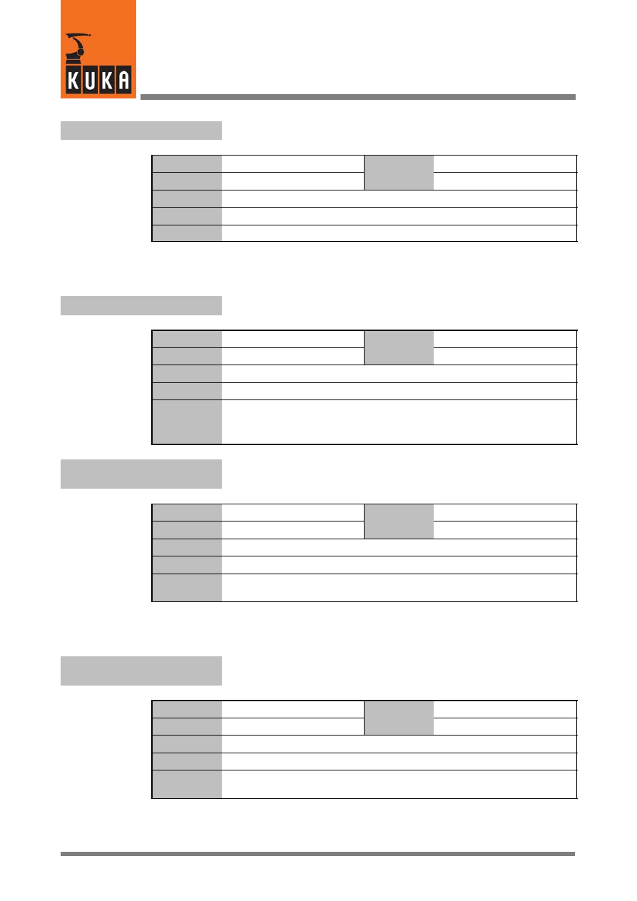
System Variables
130 of 170
SysVar 08.02.03 en
$SINT_LIST
List of interrupts at Submit level
Data type
Structure
Value
min.
Unit
Value
max.
In file
------
Original line
DECL INT_INFO $SINT_LIST[32]
Comments
This information is shown in the menu Monitor ® Diagnosis ® Interrupts.
$SLAVE_AXIS_INC
Actual position of master/slave axes in increments
Data type
Integer
Value
min.
Unit
Value
max.
In file
------
Original line
DECL SLAVE_AXIS_INC $SLAVE_AXIS_INC[12]
Comments
M: Master S1 -- S5: Slaves
e.g.: $SLAVE_AXIS_INC[6].S2
----> 2nd slave of axis 6
$SLAVE_AXIS_INC[1].M
----> master of axis 1
$SOFTN_END[n]
Position of the software limit switches at the negative end of the axis
(axes 1 ... 12)
Data type
Real
Value
min.
Unit
mm, °
Value
max.
In file
R1\Mada\$machine.dat
Original line
REAL $SOFTN_END[n]
Comments
[n] = [1] ... [6]: axis A1 ... A6
[n] = [7] ... [12]: external axis E1 ... E6
$SOFTP_END[n]
Position of the software limit switches at the positive end of the axis
(axes 1 ... 12)
Data type
Real
Value
min.
Unit
mm, °
Value
max.
In file
R1\Mada\$machine.dat
Original line
REAL $SOFTP_END[n]
Comments
[n] = [1] ... [6]: axis A1 ... A6
[n] = [7] ... [12]: external axis E1 ... E6

19
S (Fortsetzung)
131 of 170
SysVar 08.02.03 en
$SOFTPLCBOOL[n]
Data exchange between KRC and SoftPLC
Data type
Boolean
Value
min.
Unit
Value
max.
In file
------
Original line
BOOL $SOFTPLCBOOL[n]
Comments
[n] = [1] ... [1024]
Read value:
single: T_INT16 RdPLC_BOOL(T_UINT16 Index, T_FLAG * Erg);
several:T_INT16 RdPLC_BOOL_EX(T_FLAG * pBoolArray,
T_UINT16 nIndex, T_UINT16 nAmount);
Write value:
single: T_INT16 WrPLC_BOOL(T_UINT16 Index, T_FLAG Wert);
several:T_INT16 WrPLC_BOOL_EX(T_FLAG * pBoolArray,
T_UINT16 nIndex, T_UINT16 nAmount);
nIndex:
Defined position beyond which data are read
nAmount: Number of variables used
The return value sent is either “0” (reading/writing OK)
or “--1” (error reading or writing).
Options
Effect
TRUE
None, because user variable
FALSE
None, because user variable
$SOFTPLCINT[n]
Data exchange between KRC and SoftPLC
Data type
Integer
Value
min.
Unit
Value
max.
In file
------
Original line
INT $SOFTPLCINT[n]
Comments
[n] = [1] ... [1024]
Read value:
single: T_INT16 RdPLC_INT(T_UINT16 Index, T_INT32 * Erg);
several:T_INT16 RdPLC_INT_EX(T_INT32* pIntArray,
T_UINT16 nIndex, T_UINT16 nAmount);
Write value:
single: T_INT16 WrPLC_INT(T_UINT16 Index, T_INT32 Wert);
several:T_INT16 WrPLC_INT_EX(T_INT32* pIntArray,
T_UINT16 nIndex, T_UINT16 nAmount);
nIndex:
Defined position beyond which data are read
nAmount: Number of variables used
The return value sent is either “0” (reading/writing OK)
or “--1” (error reading or writing).
Options
Effect
TRUE
None, because user variable
FALSE
None, because user variable

System Variables
132 of 170
SysVar 08.02.03 en
$SOFTPLCREAL[n]
Data exchange between KRC and SoftPLC
Data type
Real
Value
min.
Unit
Value
max.
In file
------
Original line
REAL $SOFTPLCREAL[n]
Comments
[n] = [1] ... [1024]
Read value:
single:
T_INT16 RdPLC_REAL(T_UINT16 Index, T_FLOAT * Erg);
several:
T_INT16 RdPLC_REAL_EX(T_FLOAT* pFloatArray,
T_UINT16 nIndex, T_UINT16 nAmount);
Write value:
single:
T_INT16 WrPLC_INT(T_UINT16 Index, T_FLOAT Wert);
several:
T_INT16 WrPLC_REAL_EX(T_FLOAT* pRealArray,
T_UINT16 nIndex, T_UINT16 nAmount);
nIndex:
Defined position beyond which data are read
nAmount: Number of variables used
The return value sent is either “0” (reading/writing OK)
or “--1” (error reading or writing).
Options
Effect
TRUE
None, because user variable
FALSE
None, because user variable
$SPC_KIN
Data for special kinematics
Data type
Real
Value
min.
Unit
Value
max.
In file
R1\Mada\$machine.dat
Original line
REAL $SPC_KIN[30]
;Sonderkinematiken
Comments
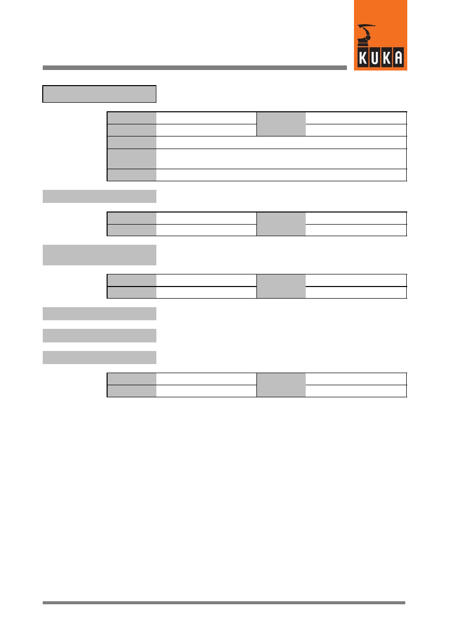
19
S (Fortsetzung)
133 of 170
SysVar 08.02.03 en
Description of the spindle drive
$SPIN_A
Data type
Structure
Value
min.
Unit
Value
max.
In file
R1\Mada\$machine.dat
Original line
DECL SPIN $SPIN_A={SPIN_AXIS 0,SPIN_RAD_G 0.0,
SPIN_RAD_H 0.0,SPIN_SG 0,SPIN_BETA 0.0}
Comments
$SPIN_A.SPIN_AXIS
Number of the axis on which the spindle acts
Data type
Integer
Value
min.
Unit
Value
max.
$SPIN_A.SPIN_BETA
Offset of the angle between sides “g” and “h” of the trapezoid
in relation to initial angle
Data type
Real
Value
min.
Unit
Value
max.
$SPIN_A.SPIN_RAD_G
Length of the static side “g” of the spindle
$SPIN_A.SPIN_RAD_H
Length of the moving side “h” of the spindle
$SPIN_A.SPIN_SG
Sign for the direction of rotation
Data type
Integer
Value
min.
Unit
Value
max.
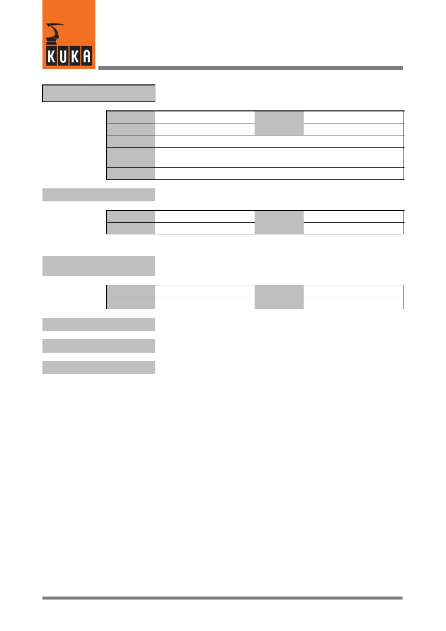
System Variables
134 of 170
SysVar 08.02.03 en
Description of the spindle drive
$SPIN_B
Data type
Structure
Value
min.
Unit
Value
max.
In file
R1\Mada\$machine.dat
Original line
DECL SPIN $SPIN_B={SPIN_AXIS 0,SPIN_RAD_G 0.0,
SPIN_RAD_H 0.0,SPIN_SG 0,SPIN_BETA 0.0}
Comments
$SPIN_B.SPIN_AXIS
Number of the axis on which the spindle acts
Data type
Integer
Value
min.
Unit
Value
max.
$SPIN_B.SPIN_BETA
Offset of the angle between sides “g” and “h” of the trapezoid
in relation to initial angle
Data type
Real
Value
min.
Unit
Value
max.
$SPIN_B.SPIN_RAD_G
Length of the static side “g” of the spindle
$SPIN_B.SPIN_RAD_H
Length of the moving side “h” of the spindle
$SPIN_B.SPIN_SG
Sign for the direction of rotation
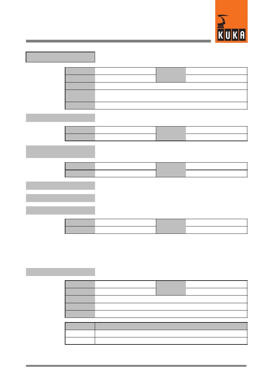
19
S (Fortsetzung)
135 of 170
SysVar 08.02.03 en
Description of the spindle drive
$SPIN_C
Data type
Structure
Value
min.
Unit
Value
max.
In file
R1\Mada\$machine.dat
Original line
DECL SPIN $SPIN_C={SPIN_AXIS 0,SPIN_RAD_G 0.0,
SPIN_RAD_H 0.0,SPIN_SG 0,SPIN_BETA 0.0}
Comments
$SPIN_C.SPIN_AXIS
Number of the axis on which the spindle acts
Data type
Integer
Value
min.
Unit
Value
max.
$SPIN_C.SPIN_BETA
Offset of the angle between sides “g” and “h” of the trapezoid
in relation to initial angle
Data type
Real
Value
min.
Unit
Value
max.
$SPIN_C.SPIN_RAD_G
Length of the static side “g” of the spindle
$SPIN_C.SPIN_RAD_H
Length of the moving side “h” of the spindle
$SPIN_C.SPIN_SG
Sign for the direction of rotation
Data type
Integer
Value
min.
Unit
Value
max.
$SPINDLE
Spindles
Data type
Integer
Value
min.
Unit
Value
max.
In file
R1\Mada\$machine.dat
Original line
INT $SPINDLE
Comments
Options
Effect
0
No
1
Yes

System Variables
136 of 170
SysVar 08.02.03 en
$SS_MODE
Signal declaration “Single step mode”
Data type
Signal declaration
Value
min.
Unit
Value
max.
In file
Steu\Mada\$machine.dat
Original line
SIGNAL $SS_MODE $OUT[999]
Comments
$ST_TOL_TIME
Standstill detection time
Data type
Integer
Value
min.
Unit
ms
Value
max.
In file
R1\Mada\$machine.dat
Original line
INT $ST_TOL_TIME
Comments
Time in ms that the robot must remain in velocity band $ST_TOL_VEL
before a standstill will be detected.
$ST_TOL_VEL[n]
Velocity limit for standstill detection
Data type
Real
Value
min.
Unit
1/min
Value
max.
In file
R1\Mada\$machine.dat
Original line
REAL $ST_TOL_VEL[n]
Comments
[n] = [1] ... [6]:
axis A1 ... A6
[n] = [7] ... [12]: external axis E1 ... E6
$STOPMB_ID
Identification of the mailbox for stop messages
Data type
Integer
Value
min.
Unit
Value
max.
In file
------
Original line
INT $STOPMB_ID
Comments
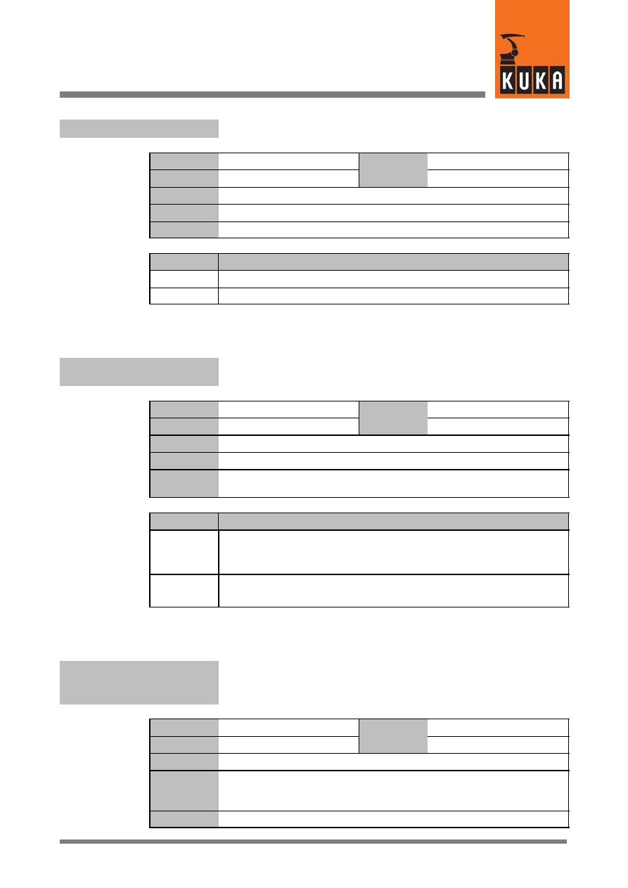
19
S (Fortsetzung)
137 of 170
SysVar 08.02.03 en
$STOPMESS
Signal declaration “Stop message”
Data type
Signal declaration
Value
min.
Unit
Value
max.
In file
Steu\Mada\$machine.dat
Original line
SIGNAL $STOPMESS $OUT[1010]
Comments
Options
Effect
TRUE
Stop message; the assigned output is set to TRUE.
FALSE
No stop message; the assigned output is set to FALSE.
$STOPNOAPROX
Message “Approximation not possible”, with or without acknowl-
edgement
Data type
Boolean
Value
min.
Unit
Value
max.
In file
------
Original line
BOOL $STOPNOAPROX
Comments
Defines whether in the event of “Approximation not possible” a notification
message or an acknowledgment message is generated.
Options
Effect
TRUE
T1/T2 mode:
Acknowledgement message “Approximation not
possible”. The robot stops.
AUT/EXT mode:
Notification message “Approximation not possible”.
FALSE
T1/T2 mode:
Notification message “Approximation not possible”.
AUT/EXT mode:
No message.
$STROBE1
...
$STROBE6
Measured--value scan, strobe for digital input 1 ... 6
Data type
Signal declaration
Value
min.
Unit
Value
max.
In file
Steu\Mada\$machine.dat
Original line
SIGNAL $STROBE1 $OUT[1015]
...
SIGNAL $STROBE6 $OUT[1020]
Comments
Strobe output for digital input 1 ... 6
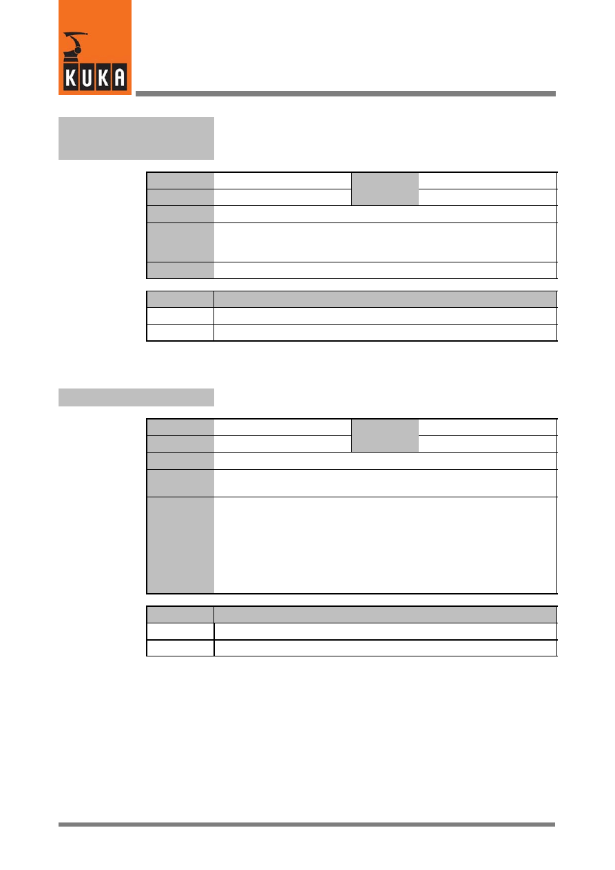
System Variables
138 of 170
SysVar 08.02.03 en
$STROBE1LEV
...
$STROBE6LEV
Strobe pulse digital input 1 ... 6 High or Low
Data type
Boolean
Value
min.
Unit
Value
max.
In file
Steu\Mada\$machine.dat
Original line
BOOL $STROBE1LEV
...
BOOL $STROBE6LEV
Comments
Active flank of the strobe output for digital input 1 ... 6
Options
Effect
TRUE
Strobe is a High pulse
FALSE
Strobe is a Low pulse
$SYNC
Generation of phase--synchronous profiles
Data type
Integer
Value
min.
Unit
Value
max.
In file
R1\Mada\$robcor.dat
Original line
INT $SYNC
;Phasenanpassung (1 = synchron, 0 = nicht synchron)
Comments
Generation of phase--synchronous profiles on/off. If acceleration
adaptation is switched on and higher motion profile is deactivated,
phase--synchronous profiles are generated for PTP individual blocks – if at
the same time $SYNC > 0. This means that all acceleration, constant travel
and deceleration phases take place simultaneously for all axes.
Thus the geometric path does not change if the motion parameters are
changed. This is not the case if $SYNC=0; in this case the axes merely start
and end motion at the same time.
Options
Effect
1
Profiles are phase--synchronous
0
Profiles are not phase--synchronous
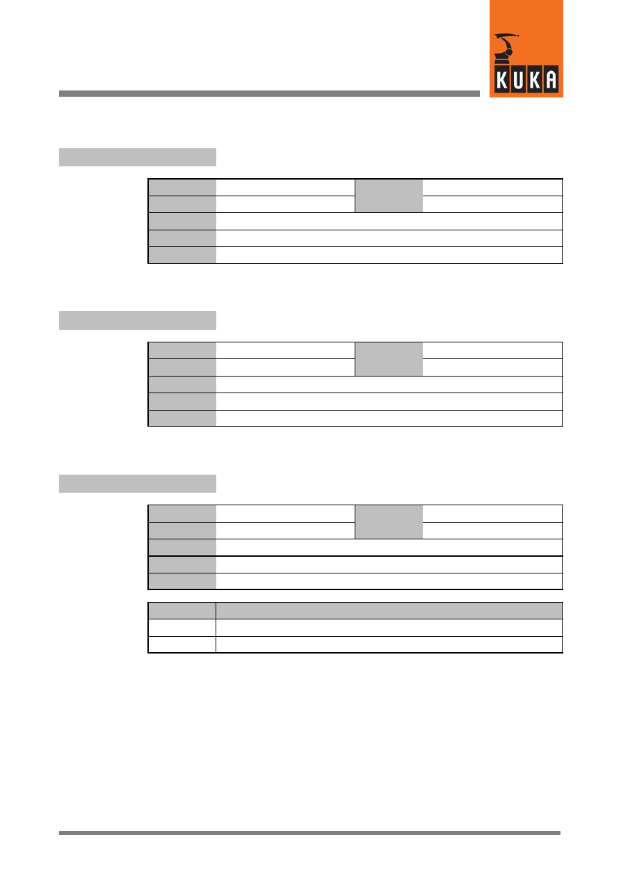
20
T
139 of 170
SysVar 08.02.03 en
20
T
$T1
Signal declaration “TEST 1 mode” – “T1”
Data type
Signal declaration
Value
min.
Unit
Value
max.
In file
Steu\Mada\$machine.dat
Original line
SIGNAL $T1 $OUT[993]
Comments
$T2
Signal declaration “TEST 2 mode” – “T2”
Data type
Signal declaration
Value
min.
Unit
Value
max.
In file
Steu\Mada\$machine.dat
Original line
SIGNAL $T2 $OUT[994]
Comments
$T2_OUT_WARNING
Warning in the event of mode change to “T2” or “AUT”
Data type
Boolean
Value
min.
Unit
Value
max.
In file
Steu\MaDa\$option.dat
Original line
BOOL $T2_OUT_WARNING=FALSE
Comments
Options
Effect
TRUE
Warning activated
FALSE
Warning deactivated
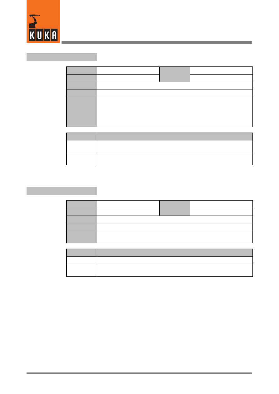
System Variables
140 of 170
SysVar 08.02.03 en
$T2_OV_REDUCE
Reduction of the override when switching to “T2”
Data type
Boolean
Value
min.
Unit
Value
max.
In file
Steu\MaDa\$option.dat
Original line
BOOL $T2_OV_REDUCE=FALSE
Comments
When the operating mode is switched to “T2”, the override is automatically
reduced to 10%.
The “T1” override setting is saved and is available once again when the
mode is switched back to “T1” (customer version 1). The default value for
“T1” (e.g. after a cold reboot) is 100%.
Options
Effect
TRUE
Override is reduced to 10% when switching to “T2” and the “T1” override
setting is saved.
FALSE
Override is not reduced when switching to “T2”. The “T1” override setting
is not saved.
$TARGET_STATUS
Selection of status for motion from start point to end (target) point
Data type
Enum
Value
min.
Unit
Value
max.
In file
Steu\MaDa\$custom.dat
Original line
DECL TARGET_STATUS $TARGET_STATUS=#SOURCE
Comments
Used by the KRL function INVERSE() if the transferred end (target) point
does not have a valid STATUS value.
Options
Effect
#SOURCE
Use Status of start point.
#BEST
All eight Status combinations are calculated; the one with the shortest
path between the start point and end point in axis space is selected.
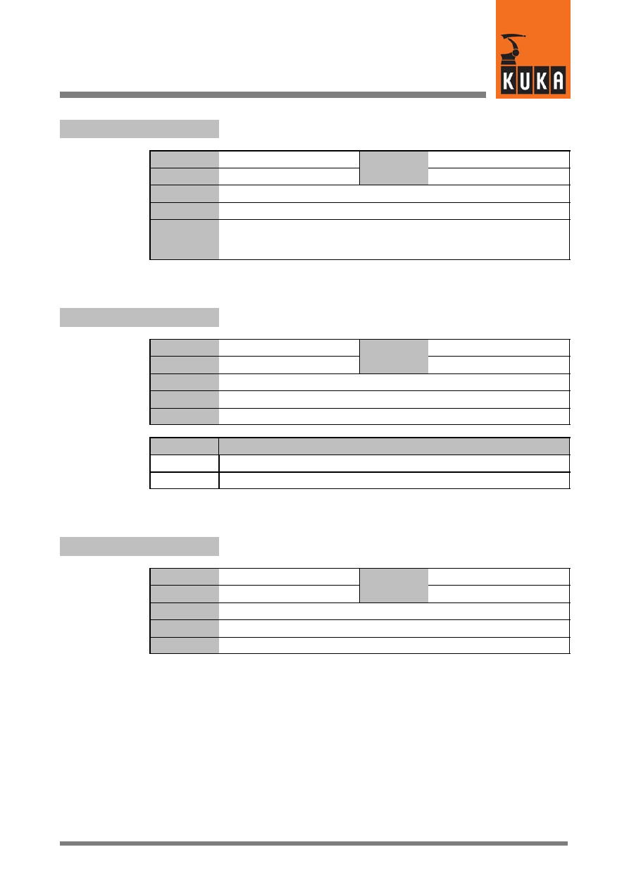
20
T (Fortsetzung)
141 of 170
SysVar 08.02.03 en
$TC_SYM
Time--constant symmetry filters
Data type
Real
Value
min.
Unit
Value
max.
In file
R1\Mada\$machine.dat
Original line
REAL $TC_SYM
Comments
The axes are made symmetrical by means of the machine datum
“$TC_SYM”. For optimum CP motion, the value of the equivalent circuit
constant of the slowest speed control loop should be entered here.
$TCP_IPO
Flag for “TCP--related interpolation” mode
Data type
Boolean
Value
min.
Unit
Value
max.
In file
Steu\Mada\$option.dat
Original line
BOOL $TCP_IPO=FALSE
Comments
Options
Effect
TRUE
“TCP--related interpolation” on
FALSE
“TCP--related interpolation” off
$TECH
Function parameters for function generator in the advance run
Data type
Enum
Value
min.
Unit
Value
max.
In file
R1\Mada\$operate.dat
Original line
DECL TECH $TECH[6]
Comments
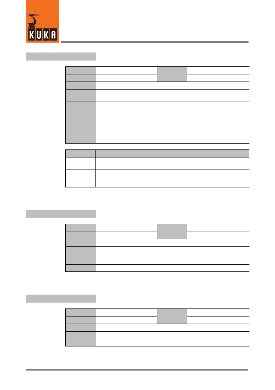
System Variables
142 of 170
SysVar 08.02.03 en
$TECH_ANA_FLT_OFF[n]
Deactivate analog output filter for Techval
Data type
Boolean
Value
min.
Unit
Value
max.
In file
Steu\Mada\$custom.dat
Original line
BOOL $TECH_ANA_FLT_OFF[n]
;Zykl. Analogausgabe des TECHVALS gefiltert
Comments
[n] = [1] ... [6]
The value of the system variable “$ANA_DEL_FLT” is ignored as soon as
one of the variables “$TECH_ANA_FLT_OFF[1] ... [6]” also has the value
“TRUE”.
If
you
wish
to
use
“$ANA_DEF_FLT”,
the
six
variables
“$ANA_DEF_FLT_OFF[1] ... [6]” and “$VEL_FLT_OFF” must be set to
“FALSE”.
Options
Effect
TRUE
The signal is not filtered so the programmed amplitude is reached exactly
and without phase shift.
FALSE
The signal is output through a filter, as previously, so the analog signal does
not quite reach the programmed amplitude and is dependent on the velocity
and the override.
$TECH_C
Function parameters for function generator in the main run
Data type
Enum
Value
min.
Unit
Value
max.
In file
------
Original line
DECL TECH $TECH_C[6]
;Funktionsparameter
Funktionsgenerator Hauptlauf
Comments
$TECH_FUNC
Functionality bits for the function generator
Data type
Integer
Value
min.
Unit
Value
max.
In file
Steu\Mada\$custom.dat
Original line
INT $TECH_FUNC=’B0000’
Comments
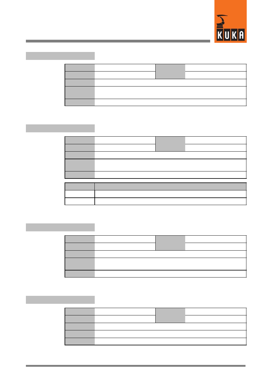
20
T (Fortsetzung)
143 of 170
SysVar 08.02.03 en
$TECH_MAX
Maximum number of function generators
Data type
Integer
Value
min.
Unit
Value
max.
In file
R1\Mada\$machine.dat
Original line
INT $TECH_MAX
;Max. Anzahl Funktionsgeneratoren
Comments
$TECH_OPT
Option bit for the function generator
Data type
Boolean
Value
min.
Unit
Value
max.
In file
Steu\Mada\$option.dat
Original line
BOOL $TECH_OPT=FALSE
;Funktionsgenerator
Comments
Options
Effect
TRUE
Function generator on.
FALSE
Function generator off.
$TECHANGLE
Rotation of the TTS in the advance run
Data type
Structure
Value
min.
Unit
Value
max.
In file
------
Original line
DECL TECHANGLE $TECHANGLE
;Verdrehung Technologiedreibein im Vorlauf
Comments
$TECHANGLE_C
Rotation of the TTS in the main run
Data type
Structure
Value
min.
Unit
Value
max.
In file
------
Original line
DECL TECHANGLE $TECHANGLE_C
Comments
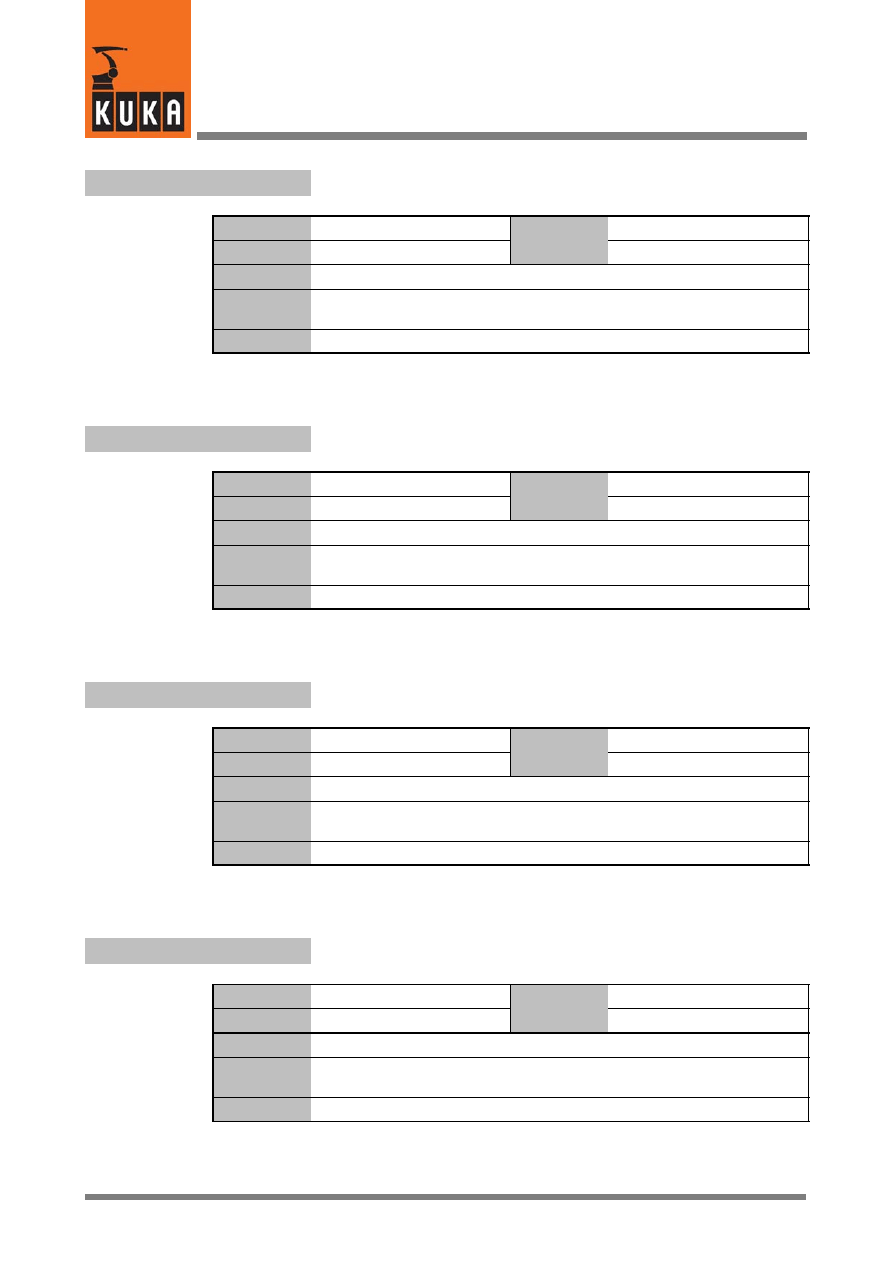
System Variables
144 of 170
SysVar 08.02.03 en
$TECHIN
Input value for function generator
Data type
Real
Value
min.
Unit
Value
max.
In file
------
Original line
REAL $TECHIN[6]
;Eingangswert Funktionsgenarator
Comments
$TECHPAR
Parameterization of the function generator in the advance run
Data type
Real
Value
min.
Unit
Value
max.
In file
------
Original line
REAL $TECHPAR[6,10]
;Parameter Funktionsgenerator
Comments
$TECHPAR_C
Parameterization of the function generator in the main run
Data type
Real
Value
min.
Unit
Value
max.
In file
------
Original line
REAL $TECHPAR_C[6,10]
;Parameter Funktionsgenerator
Comments
$TECHSYS
TTS in the advance run
Data type
Enum
Value
min.
Unit
Value
max.
In file
------
Original line
DECL TECHSYS $TECHSYS
;Technologiedreibein im Vorlauf
Comments
20
T (Fortsetzung)
145 of 170
SysVar 08.02.03 en
$TECHSYS_C
TTS in the main run
Data type
Enum
Value
min.
Unit
Value
max.
In file
------
Original line
DECL TECHSYS $TECHSYS
;Technologiedreibein im Hauptlauf
Comments
$TECHVAL
Function value for function generator
Data type
Real
Value
min.
Unit
Value
max.
In file
------
Original line
REAL $TECHVAL[6]
;Funktionswert Funktionsgenerator
Comments
$TFLWP
Offset between flange point and wrist point coordinate system
Data type
Structure
Value
min.
Unit
Frame
Value
max.
In file
R1\Mada\$machine.dat
Original line
FRAME $TFLWP={x 0.0,y 0.0,z 210.0,a 0.0,b 0.0,c 0.0}
;Frame zwischen Flansch-- und Handpunktkoordinatensystem
Comments
$TIME_POS[n]
Axis positioning time
Data type
Integer
Value
min.
Unit
ms
Value
max.
In file
R1\Mada\$machine.dat
Original line
INT $TIME_POS[n]
Comments
Maximum time for positioning of the axis.
[n] = [1] ... [6]:
axis A1 ... A6
[n] = [7] ... [12]: external axis E1 ... E6
System Variables
146 of 170
SysVar 08.02.03 en
$TIMER[n]
Timer
Data type
Integer
Value
min.
Unit
ms
Value
max.
In file
------
Original line
INT $TIMER[n]
Comments
[n] = [1] ... [32]
Value of timer[n] increases by 1 each millisecond if $TIMER_STOP = FALSE.
$TIMER_FLAG[n]
Display if timer greater than or equal to zero
Data type
Boolean
Value
min.
Unit
Value
max.
In file
------
Original line
BOOL $TIMER_FLAG[n]
Comments
[n] = [1] ... [36]
Options
Effect
TRUE
Value for timer n is greater than zero.
FALSE
Value for timer n is equal to zero.
$TIMER_STOP[n]
Start and stop the timer
Data type
Boolean
Value
min.
Unit
Value
max.
In file
------
Original line
BOOL $TIMER_STOP[n]
Comments
[n]= [1] ... [32]
Options
Effect
TRUE
Timer is stopped.
FALSE
Timer is started.
20
T (Fortsetzung)
147 of 170
SysVar 08.02.03 en
$TIRORO
Offset between internal and current robot coordinate systems
Data type
Structure
Value
min.
Unit
Value
max.
In file
R1\Mada\$machine.dat
Original line
FRAME $TIRORO={x 0.0,y 0.0,z 865.0,a 0.0,b 0.0,c 0.0}
Comments
$TL_COM_VAL
Tolerance time after exceeding the command speed limitation
Data type
Integer
Value
min.
Unit
ms
Value
max.
In file
R1\Mada\$machine.dat
Original line
INT $TL_COM_VAL=50
;Toleranzzeit Solldrehzahlbegrenzung [ms]
Comments
$TM_CON_VEL
Definition of minimum constant travel phase
Data type
Integer
Value
min.
Unit
ms
Value
max.
In file
R1\Mada\$machine.dat
Original line
INT $TM_CON_VEL
;Minimale Konstantfahrphase [ms]
Comments
To avoid sudden loading of the robot arm due to abrupt changes between
acceleration and braking (when there are short distances between points).
System Variables
148 of 170
SysVar 08.02.03 en
Tool coordinate system relative to the flange coordinate system in
the advance run
$TOOL
Data type
Structure
Value
min.
Unit
mm, °
Value
max.
In file
------
Original line
FRAME $TOOL
;Werkzeug im Flanschkoordinatensystem Vorlauf
Comments
$TOOL.A
Rotation about the Z axis
Data type
Real
Value
min.
Unit
°
Value
max.
$TOOL.B
Rotation about the Y axis
$TOOL.C
Rotation about the X axis
$TOOL.X
Offset in the X direction
Data type
Real
Value
min.
Unit
mm
Value
max.
$TOOL.Y
Offset in the Y direction
$TOOL.Z
Offset in the Z direction
20
T (Fortsetzung)
149 of 170
SysVar 08.02.03 en
Tool coordinate system relative to the flange coordinate system in
the main run
$TOOL_C
Data type
Structure
Value
min.
Unit
mm, °
Value
max.
In file
------
Original line
FRAME $TOOL_C
;Werkzeug im Flanschkoordinatensystem Hauptlauf
Comments
$TOOL_C.A
Rotation about the Z axis
Data type
Real
Value
min.
Unit
°
Value
max.
$TOOL_C.B
Rotation about the Y axis
$TOOL_C.C
Rotation about the X axis
$TOOL_C.X
Offset in the X direction
Data type
Real
Value
min.
Unit
mm
Value
max.
$TOOL_C.Y
Offset in the Y direction
$TOOL_C.Z
Offset in the Z direction
$TOOL_KIN
Name of the external TOOL kinematic system
Data type
Character
Value
min.
Unit
Value
max.
In file
------
Original line
CHAR $TOOL_KIN[29]
;Externe Kinematikachsen in TOOL
Comments

System Variables
150 of 170
SysVar 08.02.03 en
$TORQ_DIFF[n]
Maximum torque deviation of the individual axes
Data type
Integer
Value
min.
Unit
%
Value
max.
In file
------
Original line
INT $TORQ_DIFF[n]
Comments
[n] = [1] ... [6]
Specifies the maximum torque deviation in %; the only value the user can
set it to is zero.
This system variable can be used to optimize the torque monitoring
(collision detection).
Before a motion path section, the variable is set to zero in the KRL program;
at the end of a motion instruction or a motion path section, $TORQ_DIFF[]
can be read, and the monitoring tunnel $TORQMON[] set to the value of
$TORQ_DIFF[] (+5...10% safety margin).
$TORQ_VEL[n]
Velocity limitation for monitoring the torque--driven axis
Data type
Real
Value
min.
Unit
%
Value
max.
In file
------
Original line
REAL $TORQ_VEL[n]
Comments
[n] = [1] ... [6]:
axis A1 ... A6
[n] = [7] ... [12]: external axis E1 ... E6
Velocity limit in % of the maximum velocity for monitoring the torque--driven
axis [n].
When an axis is in torque mode, all monitoring functions are disabled.
Hardware defects or an axis “runaway” can nevertheless be detected by
monitoring the velocity.
The maximum permissible velocity in operating modes Automatic and T2
can be set in the program by means of $TORQ_VEL. In mode T1, the
velocity set in the machine data applies.
If this velocity is exceeded, the drives are switched off and a corresponding
error message is generated.
20
T (Fortsetzung)
151 of 170
SysVar 08.02.03 en
$TORQMON[6]
Torque monitoring tunnel in program mode
Data type
Integer
Value
min.
Unit
%
Value
max.
In file
------
Original line
INT $TORQMON[6]
;Momentenueberwachungsschlauch im Programmbetrieb [%]
Comments
$TORQMON_COM[6]
Torque monitoring tunnel in command mode
Data type
Integer
Value
min.
Unit
Value
max.
In file
------
Original line
INT $TORQMON_COM[6]
;Momentenueberwachungsschlauch im Kommandobetrieb [%]
Comments
$TORQMON_COM_DEF[6]
Default values for torque monitoring tunnel in command mode
Data type
Integer
Value
min.
Unit
%
Value
max.
In file
Steu\Mada\$custom.dat
Original line
INT $TORQMON_COM_DEF[6]
Comments
$TORQMON_DEF[6]
Default values for torque monitoring tunnel in program mode
Data type
Integer
Value
min.
Unit
%
Value
max.
In file
Steu\Mada\$custom.dat
Original line
INT $TORQMON_DEF[6]
Comments
System Variables
152 of 170
SysVar 08.02.03 en
$TORQMON_TIME
Response time of the motion torque monitoring function
Data type
Real
Value
min.
Unit
ms
Value
max.
In file
Steu\Mada\$custom.dat
Original line
REAL $TORQMON_TIME
Comments
Response time of the motion torque monitoring function.
$TORQUE_AXIS
Axis in position when command value reached – A1 ... A6, E1 ... E6
Data type
Integer
Value
min.
Unit
Value
max.
In file
------
Original line
INT $TORQUE_AXIS
Comments
Bit array for torque--driven axes A1 -- A6, E1 -- E6.
If a bit for a given axis is set, then there will be no waiting at the end of
the motion for the axis to reach its positioning window.
As soon as the command value has reached the target position, the next
block will be executed.
The axis monitoring functions are switched off.
Changing the value of this variable triggers an advance run stop.
Example:
Switch axis 1 to torque mode: $TORQUE_AXIS = ‘B000001‘
$TOUCH_ACC
Retract acceleration for touch sensor
Data type
Integer
Value
min.
Unit
%
Value
max.
In file
R1\Mada\$machine.dat
Original line
INT $TOUCH_ACC
Comments
20
T (Fortsetzung)
153 of 170
SysVar 08.02.03 en
$TOUCH_SVEL
Start velocity for touch sensor
Data type
Integer
Value
min.
Unit
%
Value
max.
In file
R1\Mada\$machine.dat
Original line
INT $TOUCH_SVEL
Comments
Start velocity of touch sensor as a percentage of the search velocity.
$TOUCH_VEL
Maximum retract velocity of the touch sensor
Data type
Integer
Value
min.
Unit
%
Value
max.
In file
R1\Mada\$machine.dat
Original line
INT $TOUCH_VEL
Comments
Parameters for the trace function
$TRACE
Data type
Structure
Value
min.
Unit
Value
max.
In file
------
Original line
DECL TRACE $TRACE
Comments
$TRACE.MODE
Trace function control
Data type
Enum
Value
min.
Unit
Value
max.
Options
Effect
#START
Start TRACE
System Variables
154 of 170
SysVar 08.02.03 en
$TRACE.NAME
Name of the file in which the data are recorded
Data type
Character
Value
min.
Unit
Value
max.
$TRACE.STATE
State of the trace function
Data type
Enum
Value
min.
Unit
Value
max.
Options
Effect
#T_WAIT
#TRIGGERED
#T_END
$TRAFO_AXIS
Number of transformed axes
Data type
Integer
Value
min.
Unit
Value
max.
In file
R1\Mada\$machine.dat
Original line
INT $TRAFO_AXIS=6
;Anzahl der transformierten Achsen
Comments
$TRAFONAME
Name of coordinate transformation
Data type
Character
Value
min.
Unit
Value
max.
In file
R1\Mada\$machine.dat
Original line
CHAR $TRAFONAME[32]
;Name der Koordinatentransformation
Comments
20
T (Fortsetzung)
155 of 170
SysVar 08.02.03 en
$TRANSSYS
Translation reference system
Data type
Enum
Value
min.
Unit
Value
max.
In file
------
Original line
DECL TRANSSYS $TRANSSYS
;WORLD, BASE, ROBROOT, TCP
Comments
Options
Effect
#WORLD
#BASE
#ROBROOT
#TCP
Trapezoidal link of the axis drives
$TRP_A
Data type
Structure
Value
min.
Unit
Value
max.
In file
R1\Mada\$machine.dat
Original line
DECL TRPSPIN $TRP_A={TRPSP_AXIS 0,TRPSP_COP_AX 0,
TRPSP_A 0.0,TRPSP_B 0.0,TRPSP_C 0.0,TRPSP_D 0.0}
Comments
Describes a trapezoidal link of the axis drives.
TRP_A.TRPSP_AXIS:
driven axis.
TRP_A.TRPSP_COP_AXIS:
coupled axis.
TRP_A.TRPSP_A, B, C and D:
lengths of the four trapezoid sides.
$TRP_A.TRPSP_A
Length of trapezoid side “A”
Data type
Real
Value
min.
Unit
Value
max.
$TRP_A.TRPSP_AXIS
Driven axis
Data type
Integer
Value
min.
Unit
Value
max.
System Variables
156 of 170
SysVar 08.02.03 en
$TRP_A.TRPSP_B
Length of trapezoid side “B”
Data type
Real
Value
min.
Unit
Value
max.
$TRP_A.TRPSP_C
Length of trapezoid side “C”
$TRP_A.TRPSP_COP_AX
Coupled axis
Data type
Integer
Value
min.
Unit
Value
max.
$TRP_A.TRPSP_D
Length of trapezoid side “D”
Data type
Real
Value
min.
Unit
Value
max.
$TSYS
Current TTS in relation to the base coordinate system
Data type
Structure
Value
min.
Unit
Value
max.
In file
------
Original line
FRAME $TSYS
;Aktuelles Technologie--Dreibein bezogen auf BASE
Comments
$TURN
Rotational adjustment active
Data type
Boolean
Value
min.
Unit
Value
max.
In file
------
Original line
BOOL $TURN
;Drehjustage aktiv
Comments
Options
Effect
TRUE
Rotational adjustment active
FALSE
Rotational adjustment not active

20
T (Fortsetzung)
157 of 170
SysVar 08.02.03 en
$TX3P3
Offset of robot wrist, based on axis 3
Data type
Structure
Value
min.
Unit
Value
max.
In file
R1\Mada\$machine.dat
Original line
FRAME $TX3P3={x 1000.0,y 0.0,z 45.0,a 0.0,b 90.0,c 0.0}
Comments

System Variables
158 of 170
SysVar 08.02.03 en
21
U
$USER_SAF
Signal declaration “Safety gate monitoring”
Data type
Signal declaration
Value
min.
Unit
Value
max.
In file
Steu\Mada\$machine.dat
Original line
SIGNAL $USER_SAF $OUT[1011]
Comments
22
V
159 of 170
SysVar 08.02.03 en
22
V
$V_CUSTOM
Version identifier of the file “$Custom.dat”
Data type
Character
Value
min.
Unit
Value
max.
In file
Steu\Mada\$custom.dat
Original line
CHAR $V_CUSTOM[32]
Comments
$V_OPTION
Version identifier of the file “$Option.dat”
Data type
Character
Value
min.
Unit
Value
max.
In file
Steu\Mada\$option.dat
Original line
CHAR $V_OPTION[32]
Comments
$V_R1MADA
Version identifier of machine data in the directory R1
Data type
Character
Value
min.
Unit
Value
max.
In file
R1\Mada\$machine.dat
Original line
CHAR $V_R1MADA[32]
Comments
$V_ROBCOR
Version identifier of the file “Robcor.dat”
Data type
Character
Value
min.
Unit
Value
max.
In file
R1\Mada\$robcor.dat
Original line
CHAR $V_ROBCOR[32]
Comments
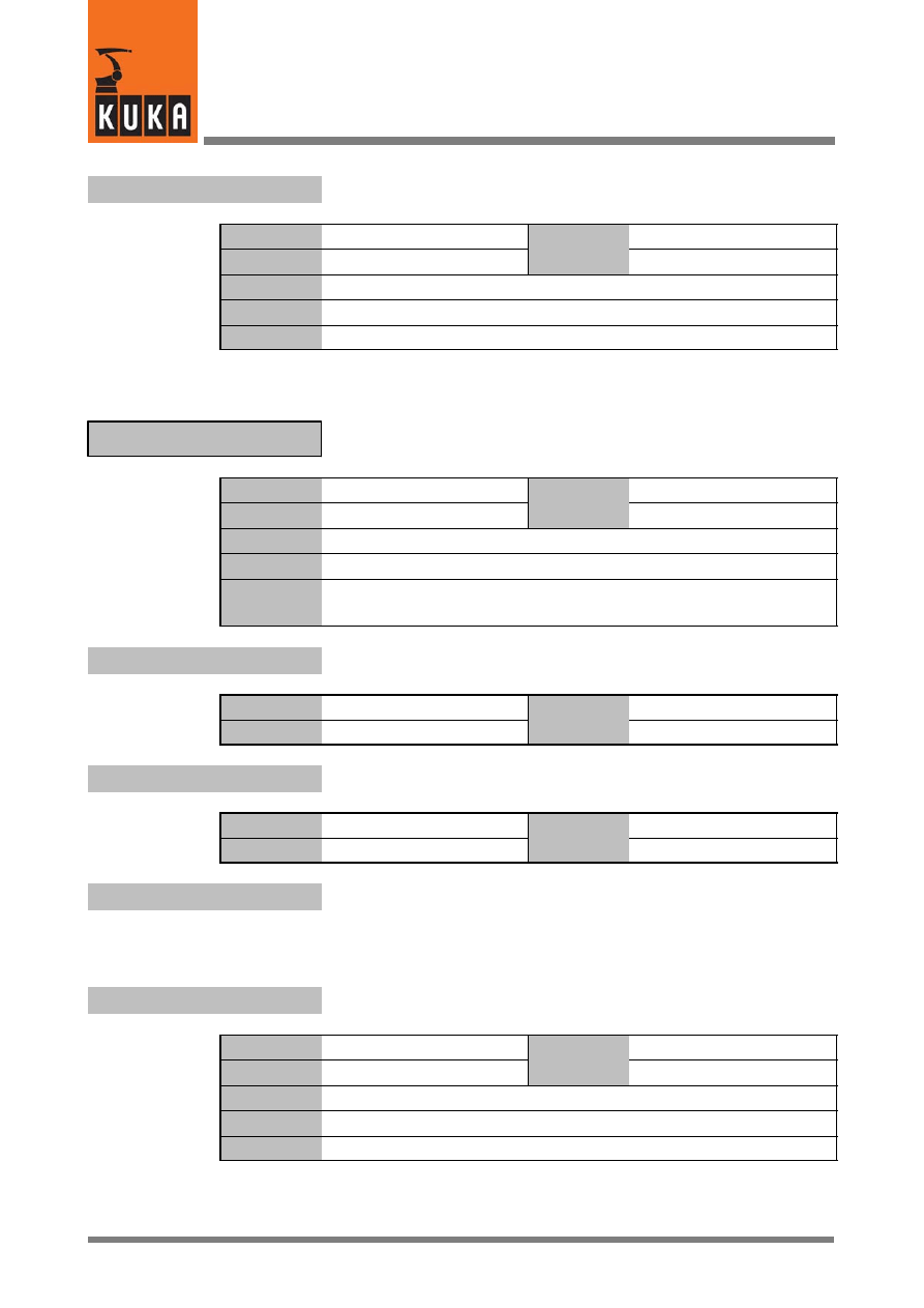
System Variables
160 of 170
SysVar 08.02.03 en
$V_STEUMADA
Version identifier of the file “$machine.dat” in the directory \Steu
Data type
Character
Value
min.
Unit
Value
max.
In file
Steu\Mada\$machine.dat
Original line
CHAR $V_STEUMADA[32]
Comments
Velocities in the advance run
$VEL
Data type
Structure
Value
min.
Unit
Value
max.
In file
R1\Mada\$machine.dat
Original line
DECL CP $VEL
Comments
Velocities in the advance run
CP = m/s, ORI1 = °/s, ORI2 = °/s
$VEL.CP
CP velocity in the advance run
Data type
Real
Value
min. > 0
Unit
m/s
Value
max.
$VEL.ORI1
Swivel velocity in the advance run
Data type
Real
Value
min.
Unit
°/s
Value
max.
$VEL.ORI2
Rotational velocity in the advance run
$VEL_ACT
Current CP velocity
Data type
Real
Value
min. > 0
Unit
m/s
Value
max. $VEL_MA.CP
In file
R1\Mada\$machine.dat
Original line
REAL $VEL_ACT
Comments

22
V (Fortsetzung)
161 of 170
SysVar 08.02.03 en
$VEL_ACT_MA
Limit value of axial command velocity
Data type
Integer
Value
min.
Unit
%
Value
max.
In file
R1\Mada\$machine.dat
Original line
INT $VEL_ACT_MA
;Grenzwert Sollgeschwindigkeit [%]
Comments
In jog mode and T1 mode, the limits are reduced by the value of the velocity
reduction factor in T1.
In PTP motions, the acceleration of the higher motion profile is calculated
on the basis of a robot model.
$VEL_AX_JUS[n]
Velocity of individual axes for EMT mastering
Data type
Real
Value
min.
Unit
°/s, mm/s
Value
max.
In file
R1\Mada\$machine.dat
Original line
REAL $VEL_AX_JUS[n]
Comments
[n] = [1] ... [6]:
axis A1 ... A6
[n] = [7] ... [12]: external axis E1 ... E6
$VEL_AXIS[n]
Velocity of the axes in the advance run
Data type
Integer
Value
min.
1
Unit
%
Value
max.
100
In file
------
Original line
INT $VEL_AXIS[n]
Comments
[n] = [1] ... [6]: axis A1 ... A6
$VEL_AXIS_ACT[n]
Current axis velocity relative to the maximum velocity
Data type
Real
Value
min.
--100
Unit
%
Value
max.
100
In file
------
Original line
REAL $VEL_AXIS_ACT[n]
Comments
[n] = [1] ... [6]:
axis A1 ... A6
[n] = [7] ... [12]: external axis E1 ... E6
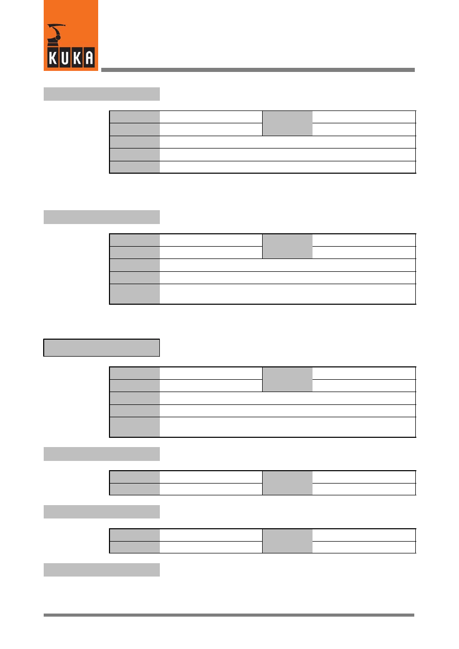
System Variables
162 of 170
SysVar 08.02.03 en
$VEL_AXIS_C[n]
Velocity of the axes in the main run
Data type
Integer
Value
min.
1
Unit
%
Value
max.
100
In file
------
Original line
INT $VEL_AXIS_C[n]
Comments
[n] = [1] ... [6]: axis A1 ... A6
$VEL_AXIS_MA[n]
Rated speed of the motors of the individual axes
Data type
Real
Value
min.
Unit
1/min
Value
max.
In file
------
Original line
REAL $VEL_AXIS_MA[n]
Comments
[n] = [1] ... [6]:
axis A1 ... A6
[n] = [7] ... [12]: external axis E1 ... E6
Velocities in the main run
$VEL_C
Data type
Structure
Value
min.
Unit
Value
max.
In file
------
Original line
DECL CP $VEL_C
Comments
Velocities in the main run
CP = m/s, ORI1 = °/s, ORI2 = °/s
$VEL_C.CP
CP velocity in the main run
Data type
Real
Value
min. > 0
Unit
m/s
Value
max.
$VEL_C.ORI1
Swivel velocity in the main run
Data type
Real
Value
min.
Unit
°/s
Value
max.
$VEL_C.ORI2
Rotational velocity in the main run

22
V (Fortsetzung)
163 of 170
SysVar 08.02.03 en
$VEL_CP_COM
Reduction factor for the flange velocity in
reorientation motions of the tool
Data type
Real
Value
min.
Unit
m/s
Value
max.
In file
R1\Mada\$machine.dat
Original line
REAL $VEL_CP_COM
;Reduzierung der Flanschgeschwindigkeit in [m/s]
Comments
$VEL_CP_T1
CP velocity in Test 1 mode
Data type
Real
Value
min.
Unit
m/s
Value
max.
In file
R1\Mada\$machine.dat
Original line
REAL $VEL_CP_T1
;Bahngeschwindigkeit in T1 [m/s]
Comments
$VEL_ENC_CO
Speed command value threshold for encoder monitoring
Data type
Integer
Value
min.
Unit
Inkr
Value
max.
In file
R1\Mada\$machine.dat
Original line
INT $VEL_ENC_CO
Comments
$VEL_EXTAX[n]
Axis velocity of the external axes in the advance run
Data type
Integer
Value
min.
Unit
%
Value
max.
Original line
INT $VEL_EXTAX[n]
Comments
[n]= [1] ... [6]: external axis E1 ... E6
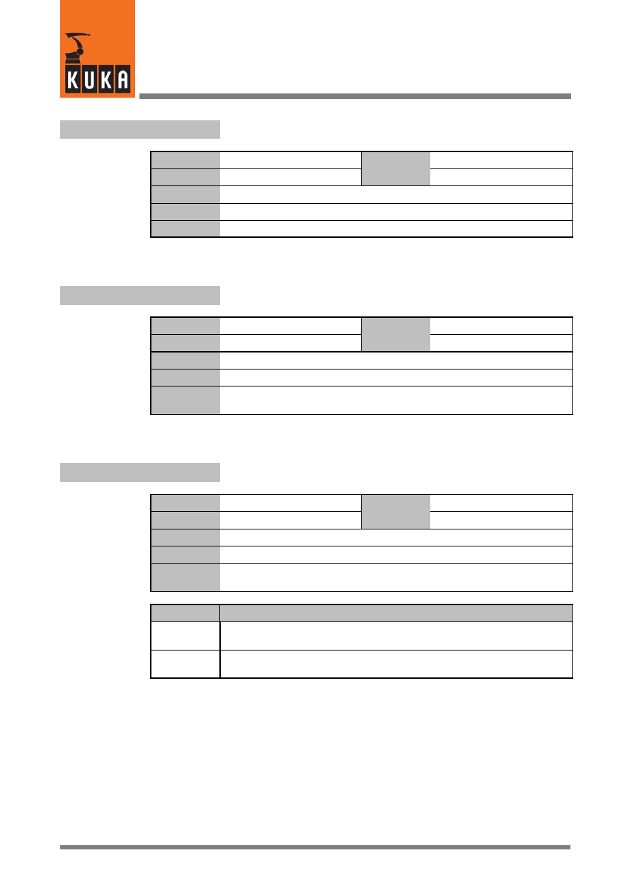
System Variables
164 of 170
SysVar 08.02.03 en
$VEL_EXTAX_C[n]
Axis velocity of the external axes in the main run
Data type
Integer
Value
min.
Unit
%
Value
max.
In file
Original line
INT $VEL_EXTAX_C[n]
Comments
[n]= [1] ... [6]: external axis E1 ... E6
$VEL_FILT[n]
Tacho filter
Data type
Real
Value
min.
Unit
ms
Value
max.
In file
R1\Mada\$machine.dat
Original line
REAL $VEL_FILT[n]
Comments
[n] = [1] ... [6]:
axis A1 ... A6
[n] = [7] ... [12]: external axis E1 ... E6
$VEL_FLT_OFF
Calculation of velocity from filtered or unfiltered setpoints
Data type
Boolean
Value
min.
Unit
Value
max.
In file
Steu\Mada\$custom.dat
Original line
BOOL $VEL_FLT_OFF=TRUE
Comments
If this variable is set to “TRUE”, the value of the system variable
“$ANA_DEL_FLT” must first be set to “ON”.
Options
Effect
TRUE
Calculation of velocity from filtered setpoints.
The velocity values need no longer be filtered.
FALSE
Calculation of velocity from unfiltered setpoints.
The velocity values must be filtered.
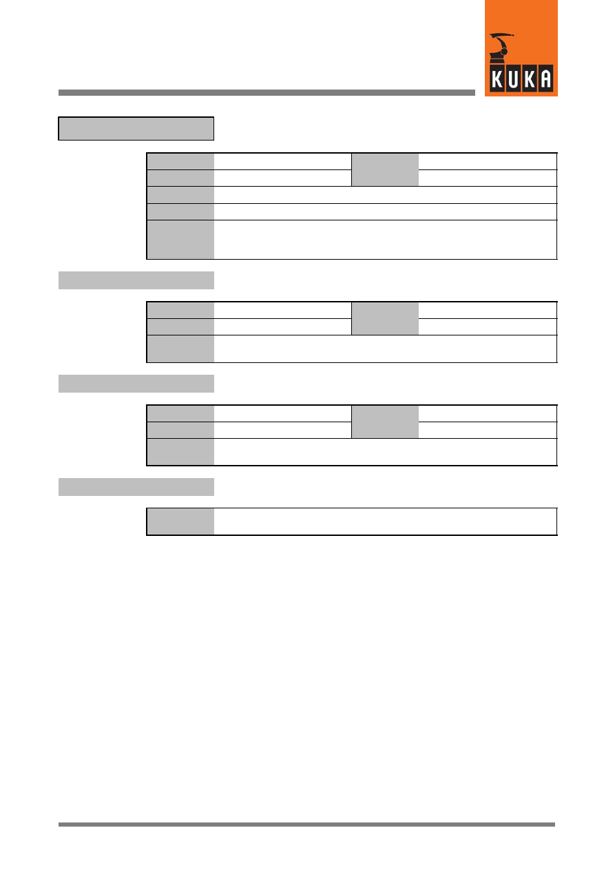
22
V (Fortsetzung)
165 of 170
SysVar 08.02.03 en
Data for maximum CP, swivel and rotational velocity
$VEL_MA
Data type
Structure
Value
min.
Unit
Value
max.
In file
R1\Mada\$machine.dat
Original line
DECL CP $VEL_MA={CP 1.75,ORI1 400.0,ORI2 400.0}
Comments
CP
= Max. CP velocity [m/s],
ORI1
= Max. swivel velocity [°/s],
ORI2
= Max. rotational velocity [°/s]
$VEL_MA.CP
Maximum CP velocity
Data type
Real
Value
min.
Unit
m/s
Value
max.
Comments
Cartesian motions are carried out with the velocity
$RED_VEL_CPC*$VEL_MA.CP
$VEL_MA.ORI1
Maximum swivel velocity
Data type
Real
Value
min.
Unit
°/s
Value
max.
Comments
Cartesian swivel motions are carried out with the velocity
$RED_VEL_CPC*$VEL_MA.ORI1
$VEL_MA.ORI2
Maximum rotational velocity
Comments
Rotational motions are carried out with the velocity
RED_VEL_CPC*VEL_MA.ORI2
System Variables
166 of 170
SysVar 08.02.03 en
23
W
$WAIT_FOR[470]
Interpreter waiting at a WAIT FOR statement
Data type
Character
Value
min.
Unit
Value
max.
In file
------
Original line
CHAR $WAIT_FOR[470]
Comments
$WAIT_FOR_ON
Interpreter waiting at a condition
Data type
Boolean
Value
min.
Unit
Value
max.
In file
------
Original line
BOOL $WAIT_FOR_ON
Comments
Options
Effect
TRUE
Interpreter is waiting at a condition
FALSE
Interpreter is not waiting at a condition
$WBOXDISABLE
Workspace monitoring on or off
Data type
Boolean
Value
min.
Unit
Value
max.
In file
------
Original line
BOOL $WBOXDISABLE
Comments
Options
Effect
TRUE
Working envelope monitoring is switched on
FALSE
Working envelope monitoring is switched off
23
W (Fortsetzung)
167 of 170
SysVar 08.02.03 en
Definition of workspace monitoring
$WORKSPACE[n]
Data type
Structure
Value
min.
Unit
Value
max.
In file
Steu\Mada\$custom.dat
Original line
DECL BOX $WORKSPACE[n]
Comments
[n] = [1] ... [8]
$WORKSPACE[n].MODE
Functional principle of the workspace monitoring function
Data type
Enum
Value
min.
Unit
Value
max.
Options
Effect
#OFF
Workspace monitoring deactivated
#INSIDE
The output is set if the TCP is located inside the workspace
#OUTSIDE
The output is set if the TCP is located outside the workspace
#INSIDE_STOP
The output is set and the robot stopped if the TCP is located inside
the workspace
#OUTSIDE_STOP The output is set and the robot stopped if the TCP is located outside
the workspace
$WORKSPACE[n].STATE
Violation of the workspace
Data type
Boolean
Value
min.
Unit
Value
max.
Options
Effect
TRUE
The workspace has been violated
FALSE
The workspace has not been violated
$WORKSPACE_NAMEn[24]
Name of the particular workspace
Data type
Character
Value
min.
Unit
Value
max.
In file
Steu\Mada\$custom.dat
Original line
CHAR $WORKSPACE_NAME1[24]
$WORKSPACE_NAME1[]=”WORKSPACE 1”
Comments
n = 1 ... 8
System Variables
168 of 170
SysVar 08.02.03 en
$WORKSTATE1
...
$WORKSTATE8
Signal declaration “Violation of workspace”
Data type
Signal declaration
Value
min.
Unit
Value
max.
In file
Steu\Mada\$machine.dat
Original line
SIGNAL $WORKSTATE1 $OUT[984]
...
SIGNAL $WORKSTATE8 $OUT[991]
Comments
Options
Effect
$OUT[n]
Output no. 1 ... 4096
FALSE
Outputs that are not required can be set to “FALSE”,
e.g. SIGNAL $WORKSTATE1 FALSE
World coordinate system relative to the initial coordinate system
$WORLD
Data type
Structure
Value
min.
Unit
mm, °
Value
max.
In file
------
Original line
FRAME $WORLD
Comments
Initial coordinate system: So--called origin coordinate system that is
identical to the World coordinate system in the KRC controller.
$WORLD.A
Rotation about the Z axis
Data type
Real
Value
min.
Unit
°
Value
max.
$WORLD.B
Rotation about the Y axis
$WORLD.C
Rotation about the X axis
$WORLD.X
Offset in the X direction
Data type
Real
Value
min.
Unit
mm
Value
max.
$WORLD.Y
Offset in the Y direction
$WORLD.Z
Offset in the Z direction

23
W (Fortsetzung)
169 of 170
SysVar 08.02.03 en
$WRIST_AXIS
Wrist axis identification
Data type
Enum
Value
min.
Unit
Value
max.
In file
R1\Mada\$machine.dat
Original line
DECL WRIST_AXIS $WRIST_AXIS=#ZEH
Comments
Options
Effect
#NOH
No wrist
#ZEH
In--line wrist
#SRH
Oblique wrist
#DSH
Triple--roll wrist
#WIH
Offset wrist
#WSH
Oblique offset wrist
System Variables
170 of 170
SysVar 08.02.03 en
24
Z
$ZERO_MOVE
Execution of a zero motion block
Data type
Boolean
Value
min.
Unit
Value
max.
In file
------
Original line
BOOL $ZERO_MOVE
Comments
The value TRUE is valid for only one interpolation cycle. Interpolation of
zero blocks only during a single interpolation cycle.
Options
Effect
TRUE
Zero motion block is executed
FALSE
No zero motion block is executed
$ZUST_ASYNC
Enable asynchronous external axes
Data type
Signal declaration
Value
min.
Unit
Value
max.
In file
Steu\Mada\$machine.dat
Original line
SIGNAL $ZUST_ASYNC $IN[1026]
Comments
Options
Effect
TRUE
Asynchronous external axes enabled
FALSE
Asynchronous external axes not enabled
1

Index
Index -- i
Zahlen
6D mouse, 127
A
Absolutely accurate robot model, 7, 8
Acceleration adaptation, 13
Acceleration of the axes in the advance run, 8
Acceleration of the axes in the main run, 9
Acceleration of the external axes, 11
Access to database, 90
Activate palletizing mode, 100
Activation of the higher motion profile, 95
Actual current of axes, 38
Actual position, Cartesian, 102
Aggregate of the end or auxiliary point, 110
Alarm Stop, 14
Alpha1 position, 128
Alpha2 position, 129
Alpha5 position, 129
Analog inputs, 14
Analog output filter, 14
Analog outputs, 15
Approximation distance, 15
Approximation not possible, 137
Assignment of axes, 51
Assignment of external axes to external axis ki-
nematic system, 57
Assignment of jog keys, 78
Assignment of the jog keys, 19
Automatic, 19
Axis 4, 7
Axis angle, 20
Axis brake, 126
Axis brakes, 31, 32
Axis coupling factors, 37
Axis identification, 26
Axis in position, 152
Axis positioning time, 145
Axis run--up time, 115
Axis servo, 126
Axis velocity of the external axes, 163
B
Base coordinate system, 29
BASE system, 12
Battery message, 81
BCO, 88
Bit array for axis brakes, 31
Block coincidence run, 88
Block number, 110
Block selection, 82
Bounce time for EMT signals, 30
Brake control mode, 32
Brake delay time for external axes, 31
C
Cartesian coordinates, 50
Cartesian robot motion, 50
Center of mass frame for the default load, 43
Clock generator, 121
Command acceleration, 8
Command execution, 112
Command torque monitoring, 114
Command velocity, 161
Constant travel phase, 147
Conversion of point coordinates, 7
Coordinate system for jogging, 37
Coordinate transformation, 154
Correction variables, 95
Coupled axis, 156
Coupling factors of axes, 60
CP motion, 50
CP velocity, 160, 162
CP velocity in Test 1 mode, 163
CP velocity in the advance run, 160
Current asynchronous motion execution state, 18
Current axis--specific robot position, 20
Current calibration in the power module, 39
Current calibration, power module, 107
Current CP velocity, 160
Current error, power module, 107
Current limitation for external axes, 39
Current limitation of axes, 40
Current limitation on axis, 39
Current temperature inside the KCP, 101
Curve length, CP motion, 50
Cyclical flag, 40
Cyclical flags, 40

Index
Index -- ii
D
Data for acceleration with changes of override, 12
Data for special kinematics, 132
Deceleration time during maximum braking, 42
Default center of mass, 44
Default filter for CP motion, 43
Default filter for PTP motion, 43
Default mass of the load on the flange, 44
Default moment of inertia of the load, 44
Default values for torque monitoring, 151
Definition of message type, 91
Denavit--Hartenberg parameters, 46
Description of the spindle drive, 133, 134, 135
Diagnosis, 107
Digital input, 47
Direction of rotation of the axis, 22
Direction of the start key, 48
Display axis mastered, 24
Display brightness, 100
Display contrast, 101
Display of axis angle, 20
Display of power failure, 106
Distance to the next exact positioning point, 49
Distance traveled during signal propagation time
in EMT, 124
Drive interfaces, 101
Drives OFF, 51
Drives ON, 51, 100
DSE, 51
E
Editing, 83
EMERGENCY STOP ramp, 118
EMT, 124
EMT mastering, 55, 77, 81, 161
Enable asynchronous external axes, 170
Enabling switch, 124
Encoder actual values, 13
Endless axes, 120
Error messages, 107
Execution of a zero motion block, 170
Extended position singularity, 129
External axes, 16, 97
External axis kinematic system, 57
External device active, 70
External kinematic, 30
External mode, 61
External power supply, 19
External program for controller node, 109
External Robroot kinematic system, 122
External start active, 61
F
Fan monitoring, 63
Five--axis robots, 96
Fixing of axis 4 when palletizing, 42
Flag for automatic mode, 62
Flag for infinitely rotating axes, 56
Flag for re--initializing the DSE, 117
Flags 1 to 1024 as global markers, 64
Following error monitoring, 64, 73
Function generator, 141
Function parameters for function generator, 141
Function value for function generator, 145
G
Gear torque monitoring, 67
H
Higher motion profile, 51, 76, 95
HOME directory setting of the compiler, 68
Home position, 23, 68
I
I/O interface active, 70
Incremental actual values, 23
Incremental dimension for external axes, 74
Incremental dimension, axis--specific, 74
Incremental dimension, Cartesian, relative to the
tool, 74
Infinitely rotating axes, 56
Input value for function generator, 144
Inputs, 72
Inputs/outputs, 75
Integer variables, 37
Integral factor of the speed controller, 70
Interbus groups, 71
Interbus slave, 71
Intermediate circuit voltage, power module, 107
Interpolation mode, 76
Interpreter waiting, 166

Index
Index -- iii
Interrupt, 105
Interrupts at robot level, 121
Interrupts at Submit level, 130
Iterations for path planning, 76
J
Jog keys, 19, 78
Jog mode, 86
Jog override, 98
Jogging, 31
K
Kernel system, 116
Kernel system version, 116
Key to the message text in the data bank, 90
Kinematic classes, 79
Kinetic energy, 56
KRL instruction executed, 109
KT factor of motors, 80
KT0 factor of servomotors, 80
L
Length of EMT mastering travel, 81
Limit switch tripped, 69
Limit value of axial command acceleration, 8
Limit value of axial command velocity, 161
Limitation of command speed, 36
Load data determination, 71
M
Main axis identification, 85
Master/slave axes, 130
Mastering difference for EMT mastering, 34
Maximum approximation distance, 15
Maximum braking, 42
Maximum CP velocity, 165
Maximum current of a KPS, 79
Maximum deceleration time for path--maintaining
Emergency Stop, 32
Maximum effective current on power module out-
put, 39
Maximum number of digital inputs, 93
Maximum number of digital outputs, 93
Maximum number of function generators, 143
Maximum orientation error for singularity--free
motion, 128
Maximum rotational velocity, 165
Maximum swivel velocity, 165
Maximum torque deviation, 150
Maximum values for path acceleration, 12
Measured--value scan, strobe, 137
Message display, 90
Message type, 91
Method for EMT mastering, 55
Mode, 19
Mode for asynchronous external axes, 17
Mode for Space Mouse, 87
Model data of the robot, 51
Module identifier for access to database, 90
Motion monitoring, 121
Motion status, 111
Motion torque monitoring, 152
Motion type in jog mode, 86
Motor run--up time without the axis being loaded,
115
Move enable, 88
Move enable signal, 89
N
Name for the variable, 49
Name of coordinate transformation, 154
Name of the block, 109
Name of the end or auxiliary point, 110
Name of the external Robroot kinematic system,
122
Name of the external TOOL kinematic system,
149
Name of the particular workspace, 27, 167
Nominal energy monitoring, 56
Null frame, 92
Number of external axes, 60
Number of robot axes, 93
Number of the softkey pressed, 90
Number of transformed axes, 154
O
Observable variables, 49
Offset, 57
Offset between flange point and wrist point coor-
dinate system, 145

Index
Index -- iv
Offset between mechanical and mathematical
zero, 85
Offset of robot wrist, 157
Online modification of servo parameters, 127
Operating hours meter, 122
Operator control device status, 45
Option bit for the function generator, 143
Orientation, 57
Orientation check, 96
Orientation control with CIRC blocks, 35
Orientation error, 128
Output of message text, 91
Outputs, 97
Overhead singularity, 128
Override, 98
Override for asynchronous external axes, 97
Override in jog mode, 45
P
Palletizing, 42
Parameterization of the function generator, 144
Parameters for the trace function, 153
Path acceleration, 8, 9, 12
Path check, 95
Path status for the programmed point, 110
Path--maintaining braking in event of operator
safety violation, 124
Path--maintaining Emergency Stop, 54
Permissible rated current, 40
Plus/minus key, 78
Position control monitoring, 89
Position of robot in world coordinate system, 122
Position of robot root point in world coordinate
system, 122
Position when interrupt is triggered, 105
Position when leaving the path, Cartesian, 106
Power failure, 106
Power module, 101, 107
Process name, 112
Process name of the robot interpreter, 112
Process name of the Submit interpreter, 112
Process pointer to current KRL process, 109
Process run mode of the robot interpreter, 111
Process run mode of the Submit interpreter, 111
Process state, 113
Program execution, 112
Program is processing an interrupt, 75
Program override, 98
Program run mode, 110
Program status, 108
Programming the EE potentiometer of DSE, 114
Proportional gain of the current controller, 66
Proportional gain of the position controller, 82
PTP points with Cartesian coordinates, 50
R
Rapid gauging, 85
Rated current, 40
Rated current of KPS, 79
Rated speed of the motors, 162
Re--initializing the digital servoelectronics (DSE),
117
Ready for Program Start, 116
Reduction factor for acceleration, 117
Reduction factor for axial acceleration, 117
Reduction factor for axial velocity, 120
Reduction factor for CP and orientation accelera-
tion, 117
Reduction factor for path--maintaining Emergency
Stop ramp, 118
Reduction factor for program in the advance run,
119
Reduction factor for sensor location run, 119
Reduction factor for T1 mode, 119
Reduction factor for velocity in referencing (refer-
ence point cam), 118
Reduction of acceleration, 118
Reduction of the CP path velocity, 38
Reference point offset, 34
Referencing direction, 47
Referencing sequence of the axes, 126
Referencing status, 121
Register for error messages, 107
Relative blocks, 123
Reorientation, 163
Reset acknowledgement messages, 36
Resolution of the position sensing system, 24
Response time of the motion torque monitoring
function, 152
Results of simulation for loop termination condi-
tion, 83
Retract acceleration for touch sensor, 152
Retract velocity of the touch sensor, 153
Revolution counter for endless axes, 120

Index
Index -- v
Robot in home position, 73
Robot interpreter, 75
Robot name, 123
Robot override, 98
Robot position, 20
Robot position at the time of an interrupt, 23
Robot position, Cartesian, 102
Robot type, 86
Robot wrist, 157
Rotation of the base coordinate system, 30
Rotation of the TTS, 143
Rotational acceleration, 8, 9, 12
Rotational adjustment active, 156
Rotational reference system for relative blocks,
123
Rotational velocity, 160
Rotational velocity in the main run, 162
S
Safety gate monitoring, 158
Sensor interface, 125
Serial number of the KCP CPU and software ver-
sion, 101
Serial number of the robot, 80
Servo parameters for DSE, 126
Signal propagation time in EMT, 124
Simulate observer’s point of view using the 6D
mouse (AnySim), 127
Simulation of inputs/outputs, 75
Single step mode, 136
Singularity, 48
Singularity--free motion, 128, 129
Smooth ramp, 64
Softkey, 90
SoftPLC, 131, 132
Software limit switches, 130
Space Mouse, 87
Special kinematics, 132
Speed command value threshold for encoder
monitoring, 163
Speed control loop, 20
Speed controller gain, 66
Spindle drive, 133, 134, 135
Standstill detection time, 136
Standstill window, 73
START, 112
Start key, 48
Start position of motion block, Cartesian, 103
Start position of the current motion block, 21
Start simulation, 83
Start velocity for touch sensor, 153
State of power module, 107
State of the Num Lock key, 94
Status for motion from start point to target point,
140
Status of motion, 89
Status of plus/minus key, 78
Status of position control monitoring, 89
Status of the Space Mouse, 87
Stop messages, 136
Strategy for singularity--free motion, 129
Structure for message display, 90
Submit interpreter, 75
Supplementary load on axis 3, 45
Switching external axes to asynchronous motion,
59
Swivel acceleration, 8, 9, 12
Swivel velocity, 160, 162
Symmetry filters, 141
System time and system date, 42
T
Tacho filter, 164
Target position of the current motion block, 22
Target position of the motion block, Cartesian,
104
TCP--related interpolation, 141
Test mode, 108
Test1 mode, 18
Time--constant symmetry filters, 141
Timer, 146
Timer display, 146
Tolerance time, 147
Tolerance window, 92
Tool coordinate system, 13
Tool coordinate system relative to the flange
coordinate system, 148, 149
Tool--based technological system (TTS), 143,
144
Torque deviation, 150
Torque feed forward control, 63
Torque monitoring tunnel in command mode,
151
Torque monitoring tunnel in program mode, 151
Touch sensor, 152

Index
Index -- vi
Trace function, 153
Trace function control, 153
Transformed axes, 154
Translation reference system, 155
Transmission ratio, 115
Trapezoidal link, 155
TTS in relation to the base coordinate system,
156
V
Velocity feed forward control, 63
Velocity limitation for monitoring the torque--driven
axis, 150
Velocity of the axes, 161
Velocity reduction factor in Test1 mode, 18
Violation of the axis--specific workspace, 27
Violation of the workspace, 28, 167, 168
W
WAIT FOR statement, 166
Workspace monitoring, 166
World coordinate system, 29, 122
World coordinate system relative to the initial
coordinate system, 168
Wrist axis identification, 169
Wrist axis singularity, 129
Z
Zero motion block, 170
Document Outline
- 1 How to use this documentation
- 2 A
- 3 B
- 4 C
- 5 D
- 6 E
- 7 F
- 8 G
- 9 H
- 10 I
- 11 J
- 12 K
- 13 L
- 14 M
- 15 N
- 16 O
- 17 P
- 18 R
- 19 S
- 20 T
- 21 U
- 22 V
- 23 W
- 24 Z
Wyszukiwarka
Podobne podstrony:
HONDA Keyless Entry System Owner's Manual
HONDA Ridgeline Rear Camera System Owner's Manual
HONDA Odyssey Security System Owner's Manual
System User Manual
DocLib 5086 FP 120, FP 130, FP 160 MIG Welding System Instruction Manual (0056 1842)
ACURA RL Rear Camera System Owner s Manual
Manual SystemDiagnostics plk
Clonezilla manual PL, Kopia partycji i dysków.Kopia systemu
Manual SystemDiagnostics plk
highways management system manual
ac heater system manual
State Highway Safety Management System Manual
Full Toroidal Variable Drive Transmission Systems in Mechanical Hybrid Systems From Formula 1 to Ro
Korg Trinity Manual Operating System version 2
manual kody bledow DTC w systemie OBDII
DoD Nuclear Weapon System Safety Program Manual
więcej podobnych podstron