
Service
Manual
DS 160
© PAT
Rev. C 06/14/02
190142_D
4
5 ERROR
CODES
5.1
Operating Errors E01 through E05
These errors are usually caused by operating in a way that is not allowed per the load charts.
Note: If an error message is displayed which is not contained in the following list, please contact the
PAT service department.
Error Code Error
Cause
Elimination
E01
Fallen below
radius range or
angle range
exceeded
• Fallen below the minimum
radius or gone past the
maximum angle specified in the
respective load chart due to
hoisting up the boom too far
• Hoist the boom down to a
radius or angle specified
in the load chart.
E02
Radius range
exceeded or
fallen below
angle range
• Gone past the maximum radius
or fallen below the minimum
angle specified in the respective
load chart due to hoisting down
the boom too far
• Hoist the boom up to a
radius or angle specified
in the load chart.
E04
Operating mode
not existing or
non permitted
slewing zone
• A non existing operating mode
has been selected
• Set the correct operating
mode for the crane
configuration in question
• The selected operating mode is
not available in the data
EPROM or blocked.
•
Check programming of the
data EPROM
• The boom is in a non-permitted
slewing zone
• Slew the crane into a
permitted area.
E05
Forbidden
length range of
the main boom
• Boom has been extended too
far or not enough, e.g. the boom
length has been moved out of
the permitted range for load
charts.
• The length sensor adjustment
was modified, e.g. cable slid off
the length sensor reel.
• Clutch between length sensor
pot and drive is defective
• Failure of the +5V-supply for the
analog part of the LMI-analog
board.
• Length potentiometer defective.
• Retract or extend boom to
the correct length.
• Retract the boom. Check
the pretention on the
cable. Open the length
sensor and carefully turn
the length pot
counterclockwise to the
detent with a screwdriver.
• Completely replace the
clutch with the drive
wheel and adjust length
sensor pot
• Check +5V-voltage. If
there is no voltage or
break down at a charge of
50 ohm approximately,
exchange LMI board.
• Replace
length
potentiometer.
Error Codes
© PAT
Rev. C 06/14/02
190142_D
5
5.2
Lockout Function Errors 07 and 08
These errors are caused by defects around the function lockouts.
Error
Code
Error
Cause
Elimination
E07
Faulty acknowledgment of the
overload relay on the connection
board.
The relay should be energized,
the 2nd contact however is
indicated to be off, or the 2nd
contact is indicated to be on
while the relay should be de-
energized.
• Overload relay or
main board are
defective
• LMI board defective
• Replace main board
E08
No acknowledgment from the
anti-two-block relay
• refer to E07
• refer to E07
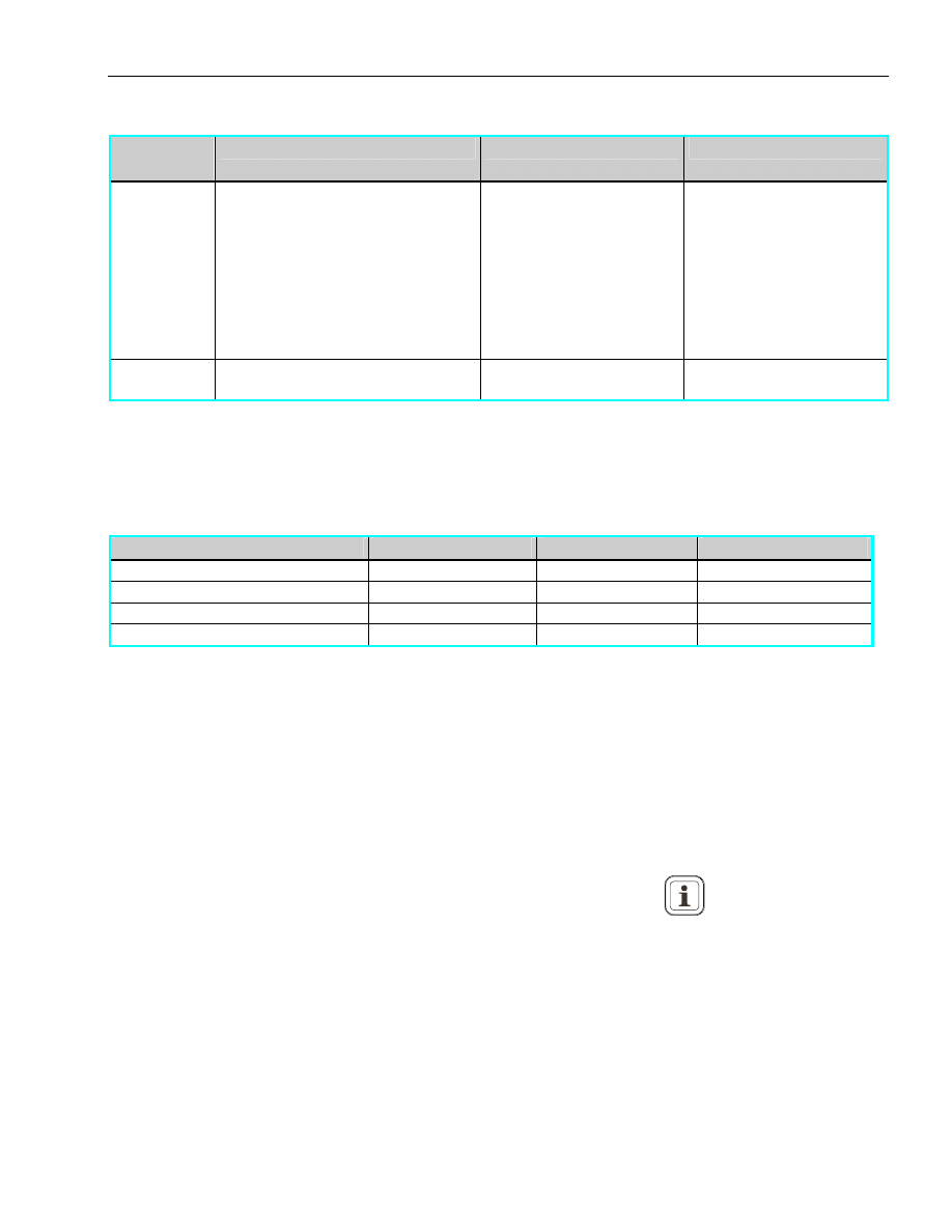
5.3
Analog Input Channel Errors
These errors occur if the input signal of an analog input channel falls below (E1x) the minimum (500V)
or exceeds (E2x) the maximum (4500V) as measured on the troubleshooting display.
The analog channels are as follows (Use theory section to define voltage or current at terminal strip):
Sensor
Pins Terminal X1
Lower Limit
Upper Limit
Piston Pressure Transducer
32 E12 E22
Rod Pressure Transducer
33 E13 E23
Length Sensor
34 E11 E21
Angle Sensor
35 E15 E25
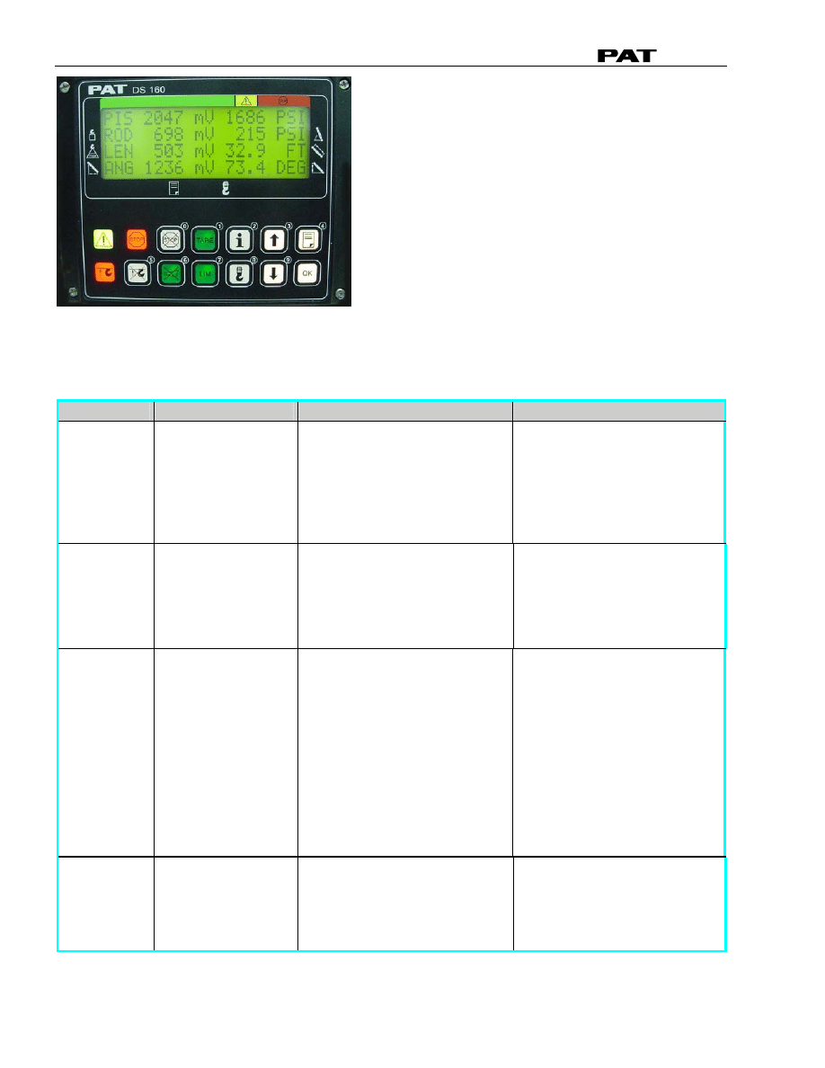
5.3.1 Troubleshooting a Sensor Problem using the Display
For a sensor error or problem with a sensor, look at the output voltage of the pressure transducer,
length, and angle sensors on the display screen and compare the reading with the following:
Pressure transducers (piston and rod), 500mV @ 0psi
Length sensor, 500mV @ retracted boom length
Angle sensor, 4500mV at 0
°, 2500mV at 45°, or 500mV at 90°
Note: The sensor output voltages displayed will not be the same as measured in the central unit.
To access the analog output screen use the following procedure.
1. From the operating screen, press and hold the information button
for 5 seconds.
2. The screen show the following selections:
• sensor
outputs
• exit
3. Use the ‘UP’ and ‘DOWN’ arrows to high light (text flashes) sensor outputs, and then press
‘OK’ to display a similar screen as shown below:
4. Press the ‘OK button to exit back to operating screen.
All Analog input voltages (shown in millivolts), received from the sensors will be displayed here as
described below. The minimum values are show in the screen pictured.
Service
Manual
DS 160
© PAT
Rev. C 06/14/02
190142_D
6
5.3.2 Error Codes for the Analog Inputs
If it exceeds these limits, the following errors are triggered: (NOTE: the upper limit follows the lower
limit error, i.e. 11 and 21, 12 and 22, 13 and 23…)
Error Code Error
Cause
Elimination
E11
Fallen below limit
for the measuring
channel "Length
telescopic boom".
• Length sensor
potentiometer defective.
• Electronic board in the
measuring channel
defective.
• Replace length sensor
potentiometer.
• Replace LMI board.
E21
Upper limit value for
measuring channel
"length telescopic
boom" exceeded.
• Length sensor
potentiometer defective.
• Electronic part in the
measuring channel
defective.
• Replace length sensor
potentiometer.
• Replace LMI board.
E12
Fallen below the
lower limit value in
the measuring
channel "pressure
piston side"
• Cable between the
central unit and pressure
transducers defective or
water inside the plugs
• Check cable as well as
plugs, replace, if need
be.
• Pressure transducer is
defective.
• Replace pressure
transducer
• Electronic component in
the measuring channel is
defective.
• Replace LMI main board
or processor board.
E22
Upper limit value
in measuring
channel "pressure
piston side" has
been exceeded
• refer to E12
• refer to E12

Error Codes
© PAT
Rev. C 06/14/02
190142_D
7
Error Code Error
Cause
Elimination
E13
Fallen below lower
limit value in the
measuring
channel "pressure
rod side"
• refer to E12
• refer to E12
E23
Upper limit value
in measuring
channel "pressure
rod side" has been
exceeded.
• refer to E12
• refer to E12
E15
Fallen below lower
limit value for the
measuring
channel "angle
main boom".
• Angle sensor defective.
• Electronic part in the
measuring channel
defective.
• Replace angle sensor.
• Replace LMI board.
E25
Upper limit value
in measuring
channel "angle
main boom"
exceeded
• refer to E15
• refer to E15
E16
Fallen below lower
limit value for the
measuring
channel "middle
section".
• Angle sensor defective.
• Electronic part in the
measuring channel
defective.
• Replace angle sensor.
• Replace LMI board.
E26
Upper limit value
in measuring
channel "middle
section" exceeded
• refer to E16
• refer to E16
E17
Fallen below lower
limit value for the
measuring
channel
"telescopic jib".
• Angle sensor defective.
• Electronic part in the
measuring channel
defective.
• Replace angle sensor.
• Replace LMI board.
E27
Upper limit value
in measuring
channel
"telescopic jib"
exceeded
• refer to E17
• refer to E17
E19
Reference and/or
supply voltage
defective
• The supply voltage is
falsified by one of the
sensors (DAV, LWG)
• Check the voltages on the
LMI main board (AGND =
MP0). Check sensors,
plugs and cable, replace, if
need be.
• Electronic component is
defective
• Replace LMI board

Service
Manual
DS 160
© PAT
Rev. C 06/14/02
190142_D
8
5.4
Errors 31 and up
Miscellaneous Errors, most of them caused by electronics.
Error Code Error
Cause
Elimination
E31
Error in the system
program
• The system program EPROM is
defective.
• Replace system program
PROM (D13)
E38
System program
and data EPROM
do not match.
• The system program in the LMI
does not match to the
programming in the data
EPROM
• Replace the system
program EPROM (D13) or
the data EPROM (D1)
E41
Error in the internal
write/read memory
(RAM) of the
computer
component 80C537
• Computer component 80C537
defective
• CPU module defective
• Processor board defective.
• Replace computer
component 80C537.
• Replace CPU module.
• Replace processor board
with CPU module.
E42
Error in the external
write/read memory,
1st part (RAM)
• Write/read memory (CMOS
RAM) or processor board
defective.
• Replace processor board
with CPU module.
E43
Error in the external
write/read memory,
2nd part (RAM)
• refer to E42
• refer to E42
E48
Error in the internal
write/read memory
(RAM)
• Computer component 80C537
defective
• Processor board defective.
• Replace processor board
(main board)
E51
Error in the data
EPROM or
EEPROM.
• No valid data in the data
EEPROM.
• Memory module wrongly
bridged.
• Crane data EPROM defective
• Load data EEPROM
containing valid data.
• Bridge memory module
acc. to memory type
• Replace crane data
EPROM
E52
Error in load chart
PROM.
• Memory module wrongly
bridged.
• Load chart EPROM defective.
• Bridge memory module
acc. to memory type.
• Replace load chart
EPROM
E56
Error in the data
EEPROM.
• Memory module wrongly
bridged.
• Crane data EEPROM defective
• Bridge memory module
acc. to memory type
• Replace crane data
EEPROM
E57
Error in serial crane
data EEPROM.
• Serial crane data EEPROM
does not contain valid data.
• Memory module defective
• Write data on the serial
crane data EEPROM (by
means of test program or
on-line function), then
restart the LMI
• Replace memory module.
E58
Error in the serial
analog data
EEPROM.
• No valid data in the serial
analog data EEPROM.
• LMI module(s) defective.
• Write data on the serial
analog data EEPROM by
means of the test
program, then, restart the
LMI
• Replace LMI module(s).

Error Codes
© PAT
Rev. C 06/14/02
190142_D
9
Error Code Error
Cause
Elimination
E82
No pressure change
sensed during
boom down or
telescope out
• Blocked velocity fuse
• No pressure change at piston
transducer
• Verify correct operation
of the velocity fuse.
E83
Error in Telecode
• The selected telecode is not
available
• Select an available
telecode
E85
Error in the radius
determination
• The computed radius is too
small (negative deflection)
• Check the programming
in the data EPROM.
E91
No data trans-
mission form the
console to the
• +UB supply voltage to the
console is interrupted
• Check +UB voltage at
terminal X1 of the console
electronics
central unit
• Interruption or accidental
ground in the line between
console electronics and central
unit
• Check the connection
console electronics -
central unit. In case of an
accidental ground, the
transmitter module of the
console electronics might
be damaged.
• Transmitter/receiver module is
defective
• Exchange console
electronics or LMI main
board resp.
E92
Error in the data
transmission from
console to central
unit
• Loose connection in the line
between console electronics
and central unit
• Transmitter/receiver module is
defective
• Check the connection
between console
electronics and central
unit
• Exchange console
electronics or LMI main
board resp.
E93
Error in the data
transmission from
the central unit to
the console
• refer to E92
• refer to E92
E94
No data trans-
mission from the
central unit to the
console
• Interruption or accidental
ground in the cable between
central unit and console
• Check wiring to the
console (in case of
accidental ground,
replace console
electronics, too).
• 5 V supply of the computer in
the central unit is missing
• Check connection to the
power unit
• 5 V supply is too low
• Exchange the LMI main
board
• Transmitter/receiver module is
defective
• Replace console
electronics or LMI main
board
• Computer module is defective
• Replace processor board.
• Electro-magnetic interferences
(e.g. when switching contactors
or valves)
• Eliminate the source of
interferences by inverse
diodes or varistors.

Service
Manual
DS 160
© PAT
Rev. C 06/14/02
190142_D
10
Error Code Error
Cause
Elimination
E95
Error in the console
EPROM
• The console EPROM is
defective.
• Replace the console
EPROM
E96
Error in the internal
RAM of the console.
• The CPU of the console is
defective.
• The console main board is
defective.
• Replace the CPU of the
console
• Replace the console main
board.
Drawings
© PAT
Rev. C 06/14/02
190142_D
25
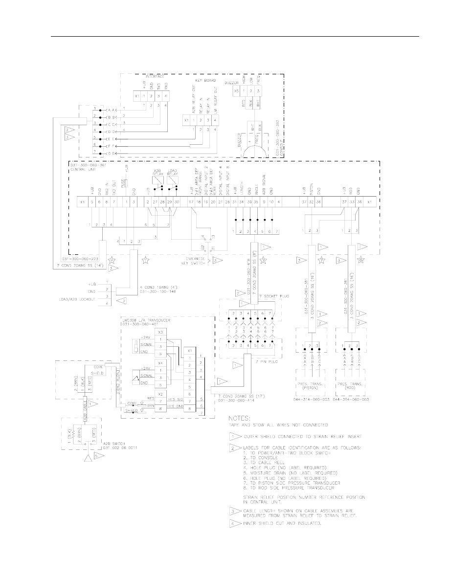
13 DRAWINGS
13.1 System Wiring Diagram
SUPPLIED BY NATIONAL CRANE
Refer to the crane owner's manual for a
complete description of the
anti-two-block system.

Procedures
© PAT
Rev. C 06/14/02
190142_D
33
14.3 Calibration of Sensors Procedure
To access the calibration sensors screen use the following procedure.
1. From the operating screen, simultaneously press and hold
and
OK
for approximately 5
seconds.
2. The screen show the following selections:
CALIBRATE SENSORS
EXIT
3. Use the ‘UP’ and ‘DOWN’ arrows to high light (text flashes) calibrate sensors, and then press
‘OK’ to display a similar screen as shown below: Note: the displayed length indication is noted
by XX.X in following step.
PIS
0.500V 000 PSI
ROD
0.500V 000 PSI
LEN
0.500V XX.X FT
ANG
0.500V 90 DEG
Go to the following selection for the pressure transducer, length, or angle procedure below to
complete sensor calibration after confirming the following step.
4. Acknowledge the sensor selection by selecting yes or no.
CALIBRATE SENSOR?
YES
NO
Proceed to the following sections for pressure transducer, length, and angle calibration procedures.
14.3.1 Pressure Transducer Calibration Procedure
After selecting ‘PIS’ or ‘ROD’ in steps 1 through 4 at the beginning of this section complete the
following procedure. The zero setting consists of defining zero-point offset. The zero point offset is
added to the transducer measurement to calculate the real physical pressure or force.
To define the zero-point offset the pressure transducer or force sensor must be in equilibrium (no load
condition). Therefore the boom must be lowered all the way down (no rest pressure) and the hydraulic
hoses disconnected from the pressure transducers.
CAUTION: Ensure there is no pressure in the hydraulic line when disconnecting the hoses from
pressure transducers.
BOOM DOWN COMPLETELY
AND DISCONNECT HYDR
OK
EXIT
Press the ‘OK’ button to zero the selected piston or rod side pressure transducer. The rod and piston
side pressure transducers are zeroed individually; therefore, you must complete this procedure for
both piston and rod side pressure transducers.
Press EXIT to leave calibration or select the ‘CALIBRATE SENSORS’ to calibrate another sensor.
Wyszukiwarka
Podobne podstrony:
PAT DS 350 Graphic Modular GM Service Data
PAT DS 350 G & GW Service Data
PAT DS 350 Graphic Modular GM Service Data
PAT DS 350 G & GW Service Data
ENGINE MECHANICAL Service data
ENG DS 1 1414305 0 DATA SHEET 1
Prezentacja firmy MARSTATE SERVICE BHP PPOZ PPT
PaT eczki G( ), niefermentujT ce
Gatunki dziennikarskie licencjat PAT czesc 2
Mazowieckie Studia Humanistyczne r2001 t7 n2 s157 160
160 SC DS400 C VW GOLF V A 05 XX
CW2006EX Mill Turn data sheet web
hplj 5p 6p service manual vhnlwmi5rxab6ao6bivsrdhllvztpnnomgxi2ma vhnlwmi5rxab6ao6bivsrdhllvztpnnomg
3 Data Plotting Using Tables to Post Process Results
An%20Analysis%20of%20the%20Data%20Obtained%20from%20Ventilat
233511 DS
Homework Data Structures
więcej podobnych podstron