
Applications Automation
Positioning Module ZB 4-256-SP1 for synchronous
and non-synchronous axes
Description Hardware Engineering, Communication,
Master-PLC Program, Starting up
Version 1.0 REF: D
Subject to alteration without notice
+ synchronous and non-synchronous positioning logic
+ up to 3 axes per positioning module
+ n-axes-positioning via Suconet K
+ electrical and hydraulic axes
+ small cycle periods
+ standardised build up
+ rapid start up
6/97 AWB-EM 27-1296-GB
1st published 1997, edition 6/97
© copyright Klöckner-Moeller, Hauptverwaltung, Hein-Moeller-Str. 7–11, 53115 Bonn, Germany
Author:
Dr. Jürgen Bechtloff, Peter Stammerjohann
Translator:
Iwona Cramer
h1296g_u.fm Seite 1 Mittwoch, Februar 11, 1998 2:37 PM

Caution!
Dangerous electrical voltage!
Before commencing the installation
● Connect devices with the power supply
switched off.
● Ensure that devices cannot be accidentally
restarted.
● Verify isolation from the supply.
● Earth and protect against short circuits.
● Cover or enclose neighbouring units that are
live.
● Follow the engineering instructions (AWA) of
the device concerned.
● Only suitably qualified personnel may
intervene with this device/system.
● Connecting cables and signal lines should be
installed so that inductive or capacitive
interference do not impair the automation
functions.
● Install automation devices and related
operating elements in such a way that they
are well protected against unintentional
operation.
● Suitable safety hardware and software
measures should be implemented for the I/O
interface so that a line or wire breakage on
the signal side does not result in undefined
states in the automation devices.
● Ensure a reliable electrical isolation of the low
voltage for the 24 volt supply. Only use power
supply units complying with IEC 364-4-41 or
HD 384.04.41 (VDE 0100 Part 401).
● Deviations of the mains voltage from the rated
value must not exceed the tolerance limits
given in the specifications, otherwise this may
cause malfunction and dangerous operation.
● Emergency stop devices complying with
EN 60204/IEC 204 (VDE 0113) must be
effective in all operating modes of the
automation devices. Unlatching the
emergency-stop devices must not cause
uncontrolled operation or restart.
● Built-in devices for housings or control
cabinets must only be operated and
controlled after they have been installed with
the housing closed. Desktop or portable units
must only be operated and controlled in
enclosed housings.
● Measures should be taken to ensure the
proper restart of programs interrupted after a
voltage dip or failure. This should not cause
dangerous operating states even for a short
time. If necessary, emergency-stop devices
should be implemented.
IBM is a registered trademark of
International Business Machines
Corporation.
All other brand and product names are
trademarks or registered trademarks of the
owner concerned.
All rights reserved, including those of the
translation. No part of this manual may be
reproduced in any form (printed, photo-
copy, microfilm or any other process) or
processed, duplicated or distributed by
means of electronic systems without the
written permission of Moeller
, Bonn.
Subject to alteration without notice.

Table of Contents
2 THE PRINCIPLE OF POSITIONING WITH A DRIVE ...............................................6


Positioning Module ZB4-256-SP1
01/98 AWB-EM 27-1296-GB
5
TIP
Please read this manual carefully before starting the positioning module!
1 Introduction
The positioning module allows flexible remote positioning with a master PLC. Coupling is
achieved by a field bus system Suconet K.. The positioning module, as with application
software, is implemented on very efficient hardware.
Alterations by the user are not necessary in this area. All essential system and axis
parameters are indicated via the communication protocol. An efficient positioning is possible
due to the integration of the positioning module into the master PLC software. A master PLC
(compact PLC: PS4-201-MM1, modular PLC: PS416) can be linked to one or more
positioning controllers via Suconet K.
1.1 Quick Reference
Technical Data
Basic Hardware
PS4-401-MM2, ZB4-256-SP1
Number of Axes
3
Type of Movement
asynchronous point-to-point axes
Resolution
digital 16 Bit (65535 increments)
analogue 12 Bit (4095 increments)
Resolution set speed value
12 Bit (
±
10V)
Supported Encoder Systems (can be combined as required)
l
digital-absolute binary code
l
incremental 5V
l
digital-absolute Gray code
l
incremental 24V
l
analogue absolute
l
Suconet K via master PLC
Communication
l
Suconet K (20 Bytes send, 17 Bytes receive)
l
address is set via DIP switch
l
order-oriented protocol
l
cyclic status-reply of the positioning module
l
parameterable demand data channel
Axis Parameter (electrical and hydraulic axes)
l
rated speed
l
In-Position window
l
ramp-up time
l
KV-Factor
l
encoder resolution
l
precontrol factor
l
Software-Limits
l
friction grip compensation
Positioning Module ZB4-256-SP1
01/98 AWB-EM 27-1296-GB
6
1.2 Who needs to read what?
•
Basics for position control/positioning technique
⇒
Chapter 2
PLC programming - introduction
•
Protocol
⇒
Chapter 4, 5
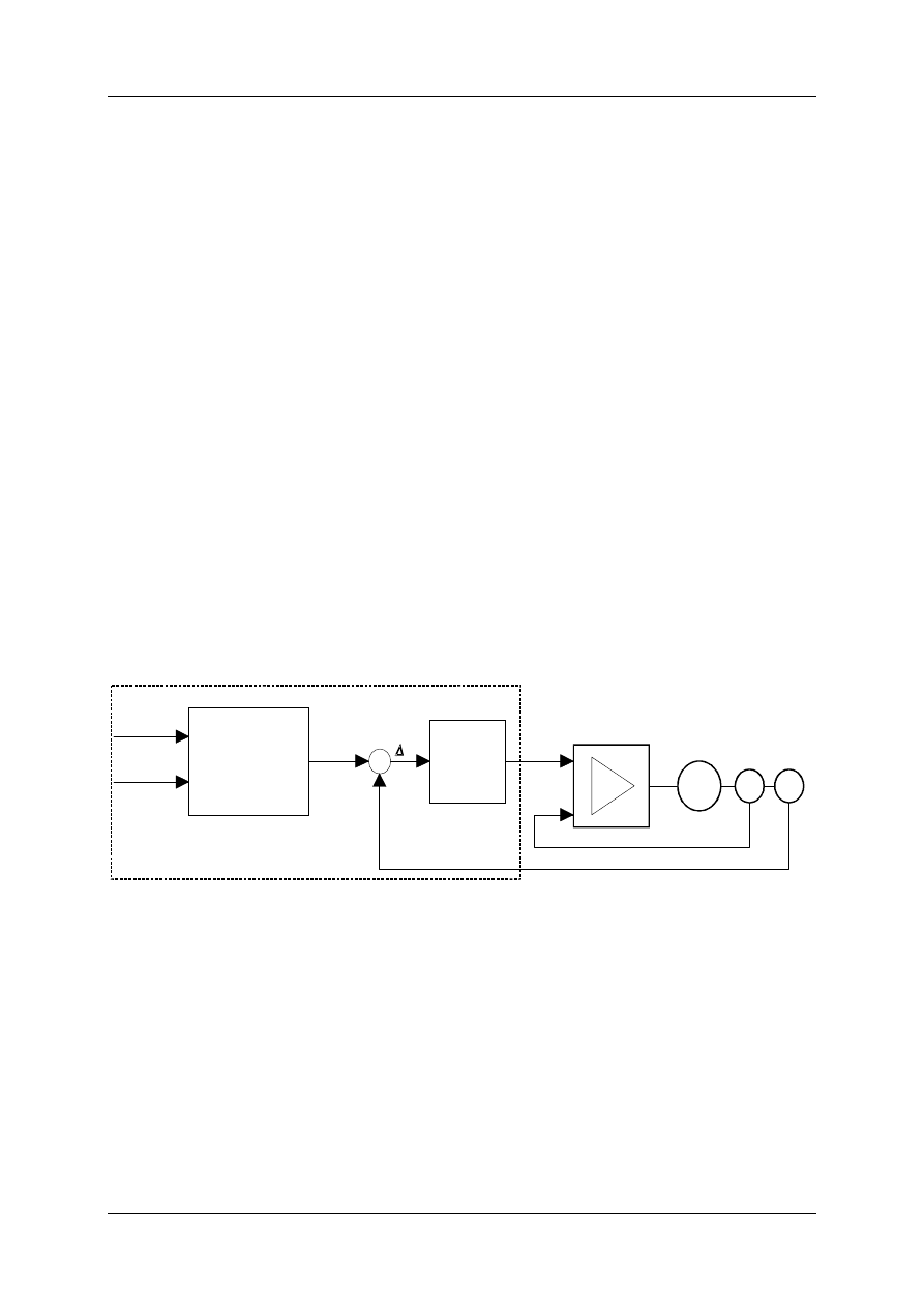
2 The Principle of Positioning with a Drive
The positioning module is a component of the position control loop (Figure 1). The controll
variable - the actual position (s
act
), a unit of a mechanical movement - is fed into and
compared with the command variable (set path s
set
). The lag error (
∆
s) is calculated by the
difference between the actual position and the command variable (
∆
s=s
act
-s
set
). A set rev
speed value (n
set
) as an analogue voltage to the servo drive is omitted depending on the
actual lag error (
∆
s). The command variable calculates the value for the positioning module
based upon the indicated target position on the master PLC and the indicated speed per
axis.
The speed control of the internal drive compares the actual rev. speed value (n
actual
) with the
set rev. speed value (n
set
) and controls the current controller
.
TargetPos
Speed
Generating
comm.
variables
s
s
position
control
Servo-
amplifier
M
T
G
n
set
n
actual
set
Motor
Tacho-
generator
encoder
-
Positioning Control
act
s
Figure 1: The Position Control Loop
2.1 Generating the Command Variables
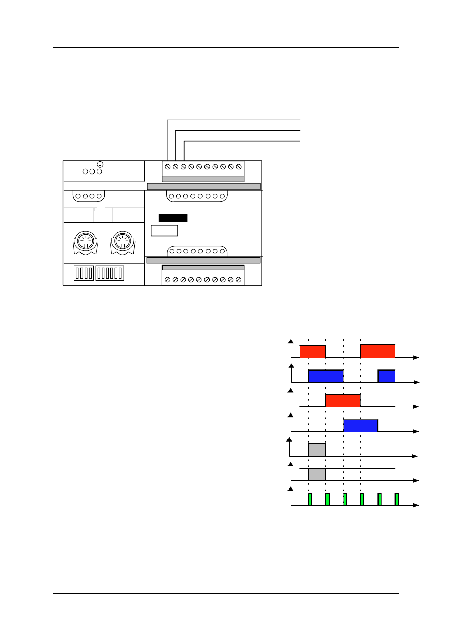
The position control works cyclically within a 6ms time frame. A command variable is
calculated in each cycle depending on the maximum speed (V
max
) and the target position.
This results in continuous movement of the drive. The resulting movement of the axis is
divided into three phases:
•
Accelerating phase
•
Phase of constant speed
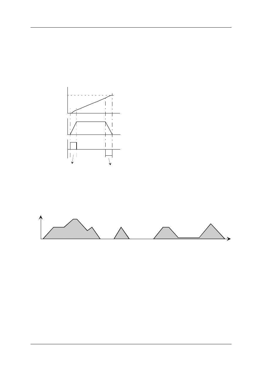
Positioning Module ZB4-256-SP1
01/98 AWB-EM 27-1296-GB
7
•
Braking phase
Switching of each of the phases depends upon the indicated ramp-up time (t
h
) of the drive to
its rated speed. Generating the command variables of the positioning modules produces a
constant acceleration or delay in the acceleration and brake phase. This results in a
symmetrical path of the speed ramp. Figure 2 shows an example of path, speed and
acceleration.
The generation of the command variables allows a change of the momentary process speed
at any time, this movement is then slowed down or accelerated (Figure 3) depending on the
momentary speed conditions. The speed indication can be absolute or assessed as a
percentage with a speed override. This speed override refers to the momentary valid
maximum speed, which can be freely chosen in the area of <= the rated speed of the drive.
Time
v(t)
Figure 3: Example for Speed Shapes
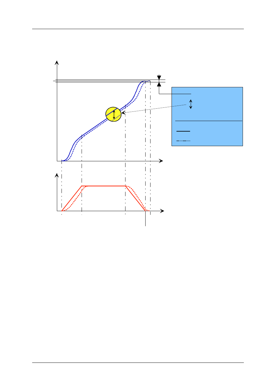
2.2 Moving the Axis towards the Target Position
A servo axis shows a finite dynamic. This means that an axis only processes a finite
acceleration. During movement the axis runs behind the calculated set position. The term for
the difference between the set and actual position is the lag error. The lag error is dependant
on the axis dynamic and the strengthening factor of the position control. The positioning is
complete when the actual position lies within the In-Position window. The In-Position window
conveys the tolerance to the predetermined position when it has reached its destination. It
can take some time for the exact target position of the axis to be reached and registered on
the master PLC if the In-Position window is very small .
s(t)
v(t)
a(t)
t
t
t
Accelaration phase
Brake phase
Targetpos
.
Start pos.
Figure 2: Process Time of an Axis Movement
Positioning Module ZB4-256-SP1
01/98 AWB-EM 27-1296-GB
8
Figure 4 shows effects of the lag error with an axis on the path and speed level. If the axis
registers an In-Position, it is then ready to execute a new Job.
Time
Speed
Set-Path/Speed
Actual Path/Speed
Path
In-Position Window
Target
Positio
n
Start-
Pos.
accelar.
v-const.
brakes
In-Position
T
Line-End
T
Lag error
Set-Path (Command
vairables)
- actual path (actual-Position)
= Lag error
Time
Figure 4: Dynamic Axis Movement
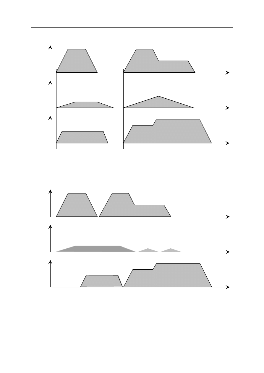
2.3 Positioning Procedure with several Axes
An asynchronous point-to-point positioning is achieved by the positioning module. All three
axes can be commanded and positioned, independent of one another. A start
synchronisation between the individual axes can be indicated in the master PLC. A
commanded axis starts moving as soon as is initialised and released. If the predetermined
path is long enough, the axis accelerates to full speed and brakes when it nears its
destination.
If more than one axis has been activated within one Job, the axes usually reach their
positions at different times depending on (Figure 5):
•
the predetermined path
•
the defined ramp-up time to the rated speed
•
the actual maximum speed and the Feed-Override
Positioning Module ZB4-256-SP1
01/98 AWB-EM 27-1296-GB
9
v
Axe1
Time
v
Axe2
Time
v
Axe3
Time
Start
Start
Feed-Override
Order ready
Order ready
Figure 5: Point-to-Point-Positioning with 3 Axes, Synchronous Start
The following Figure shows an example for an asynchronous positioning process.
v
Axe1
Time
v
Axe2
Time
v
Axe3
Time
Figure 6: Asynchronous Point-to-Point-Positioning with 3 Axes
The corresponding bits from the status response are available for controlling the axes.
Positioning Module ZB4-256-SP1
01/98 AWB-EM 27-1296-GB
10
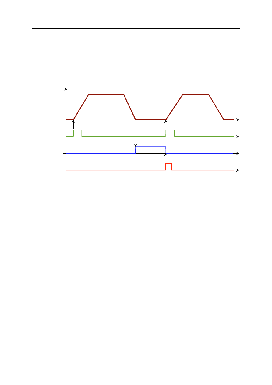
2.4 Rapid Synchronising Jobs
The positioning module allows the commanding and starting of a Job as well as the rapid
start with hardware signals. These signals are from connections to a local expansion module
LE4-116-DD1 (8 digital inputs, 8 digital outputs) which must be connected to the LE-Bus of
the PS4-401-MM2, the position of these LE's is not critical. The possibilities of this are
illustrated in the following Figure.
v
Start Signal
End Signal
ReSet Signal
0
1
0
1
0
1
t
t
t
t
Figure 7: Hardware Signals for Jobs
The initial Job begins when the start signal changes from 0 to 1, this signal corresponds with
one or more digital inputs on the LE4-116-DD1. If the Job is complete and the actual axis
has reached the In-Position, one or more of the digital outputs can be set on the LE4-116-
DD1. Starting an additional Job requires that one or more digital outputs of the LE4-116-DD1
be used for the reset signal.
3 Hardware Engineering
The basis for the positioning module is the compact PLC PS4-401-MM2 with the local
expansion modules (LE) in order to connect the encoder systems. All control and release
signals relevant for security are managed by the PS4-401-MM2. The digital encoder signals
are read by the LE module, the analogue encoder signals are directly read by the PS4-401-
MM2.
TIPS:
•
The S3 switch, located on the PS4-401-MM2, must be in position 3 (Run M-Reset).
•
The Flash-RAM-Memory module (ZB4-256-SP1) with the standard application software
'Positioning' must be installed on the PS4-401-MM2.
Positioning Module ZB4-256-SP1
01/98 AWB-EM 27-1296-GB
11
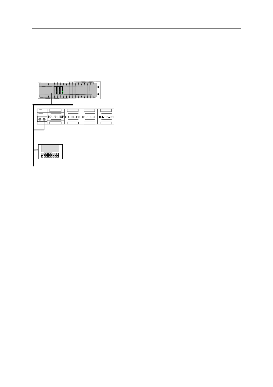
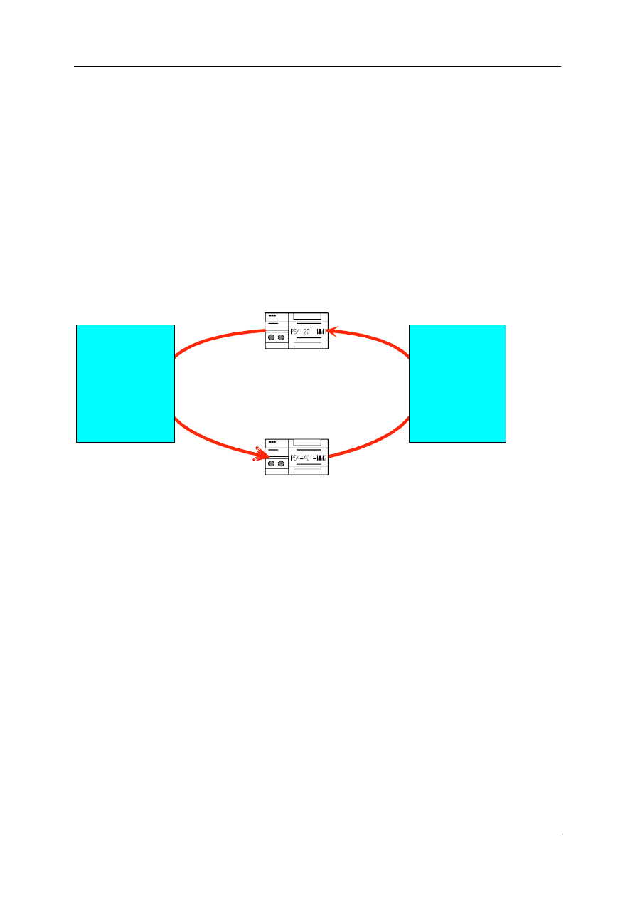
3.1 Networks
One or more positioning PLC´s can be connected to one master PLC (compact PLC: PS4-
201, modular PLC: PS416) on one Suconet K line (Figure 8).
PS 416
SUCOcontrol
POW-
400
CPU-
400
OUT-
400
OUT-
400
OUT-
400
Master-PLC
Positioning Module
MMI
Figure 8: Network Concept
The master PLC transmits 20 bytes of data to the slave positioning module. The slave
responds with 17 bytes of data.
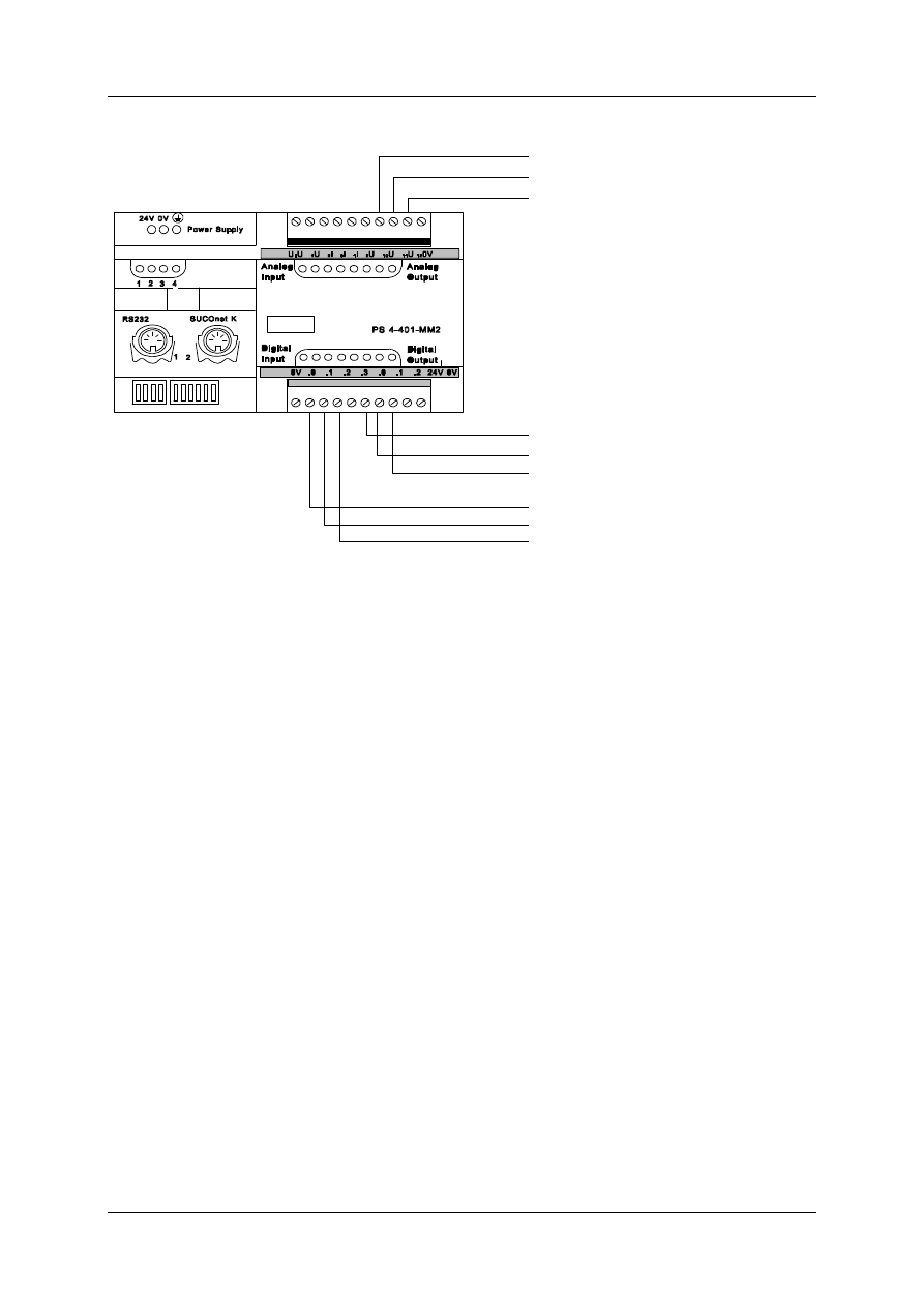
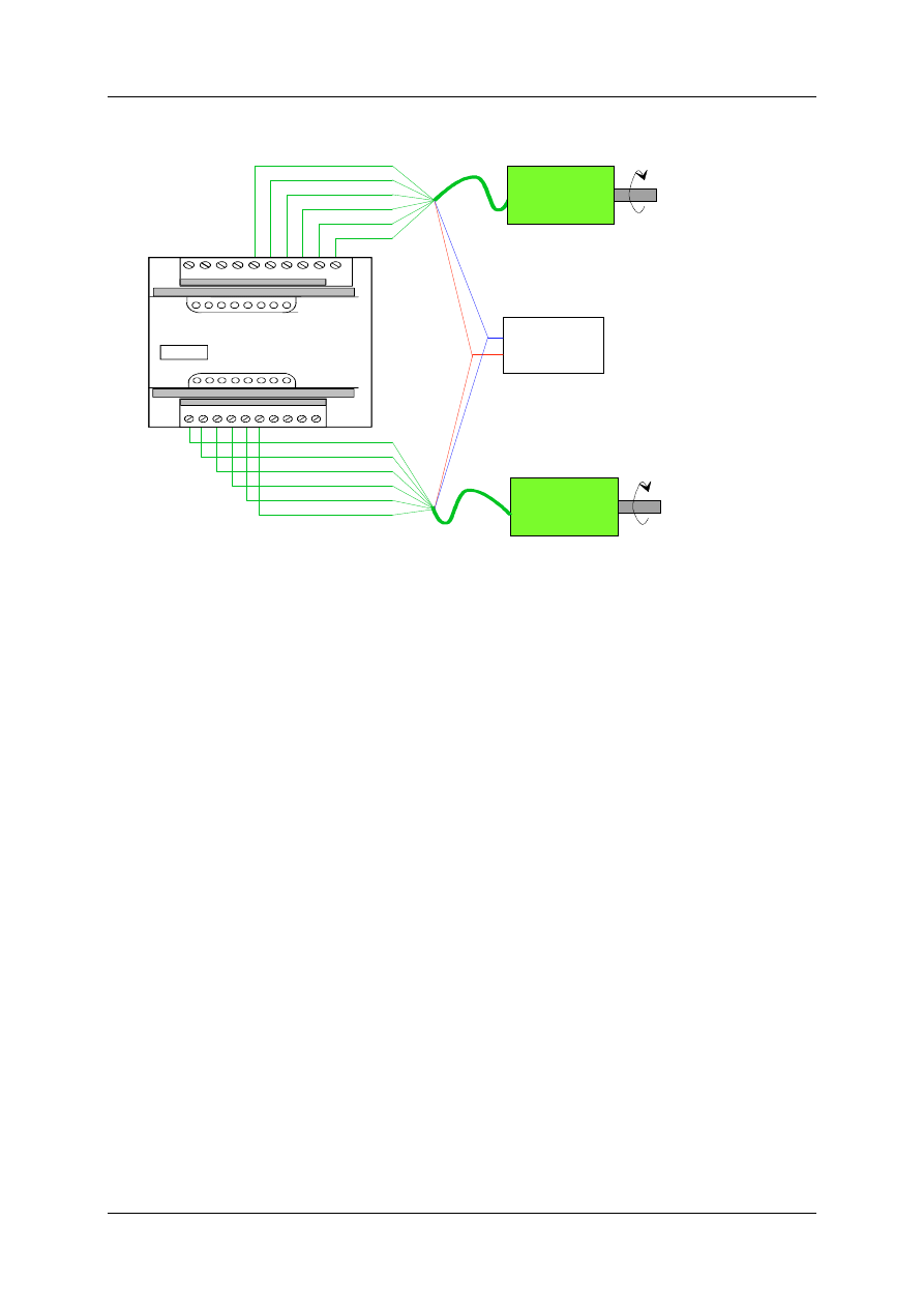
3.2 Connecting the Servo Amplifiers
The positioning module can be operated with up to three servo axes. The controller release
of the individual servo amplifiers is generated by digital outputs (Q0, Q1, Q2). The servo
amplifiers indicates controller’s stand-by to the digital inputs (I0, I1, I2). The analogue outputs
(U10, U11, U12) control the servo amplifiers with the set rev speed (n
set
Positioning Module ZB4-256-SP1
01/98 AWB-EM 27-1296-GB
12
n
set
: Axe 1 (+/-10V)
n
set
: Axe 1 (+/-10V)
n
set
: Axe 1 (+/-10V)
controller release axe 1
controller release axe 2
controller release axe 3
controller ready axe 1
controller ready axe 2
controller ready axe 3
Figure 9: Signal Assignment for three Axes
3.3 Connecting Encoder Systems
Various encoder system connections are supported:
•
absolute encoder systems, wired parallel, Gray-Code
•
absolute encoder systems, wired parallel, Binary-Code
•
absolute encoder systems, analogue voltage
•
incremental encoder systems
•
transmission of the set value from the master PLC via Suconet K (absolute and
incremental encoder signals)
The type of encoder system being used is configured during the initialisation of each axis.
It is also possible to operate the positioning module in the test-mode without an encoder
connected.
3.3.1 Absolute-Digital-Encoder
An advantage of absolute encoder systems is that they do not require a reference signal
because the absolute path information is supplied immediately after activating the power
supply. Absolute encoder systems must be connected in a parallel-bit form. The following
codes are supported:
a) parallel-binary coding (e. g. with Stegmann SPA3-module of SSI-Gray code) and
b) parallel-gray coding
Positioning Module ZB4-256-SP1
01/98 AWB-EM 27-1296-GB
13
The encoder signals are switched directly to the digital inputs of the local expansion module
LE4-116-DX1 (Figure 10). The lowest bit is switched to the I0 input. The encoder must be
separately supplied with 24 V.
S U C O c ontrol
LE 4-116-D X1
.0 .1 .2 .3 .4 .5 .6 .7
.8 .9 .1 0 .1 1 .12 .13 .1 4 .15
24 V 0V
D igital
Input
D igital
Input
1 8
A b s o lute -E n c o d e r
(G ra y-C o d e /
b in a ry-co d e )
D 7
D 6
D 5
D 4
D 3
D 2
D 1
D 0
D 15
D 14
D 13
D 12
D 11
D 10
D 9
D 8
G N D
+ 24 V
Figure 10: Connection of Absolute Parallel Encoder Systems
TIP:
The LE4-116-DX1 expansion modules (to which the absolute digital encoders
are connected) must be plugged in directly to the right of the LE4-622-CX1 modules,
if present.
The LE4-116-DX1 modules which are used to connect reference cams (incremental
axes) must be connected to the right of the LE4-116-DX1 modules used for the
absolute encoder!
Example of Configuration:
PS4-401-MM2
LE4-
622-
CX1
LE4-
116-
DX1
LE4-
116-
DX1
AX2-Incr.
AX1-Incr.
AX3-Abs
Ref.-Cams (AX1 & AX2)
Figure 11: Configuration Example
Positioning Module ZB4-256-SP1
01/98 AWB-EM 27-1296-GB
14
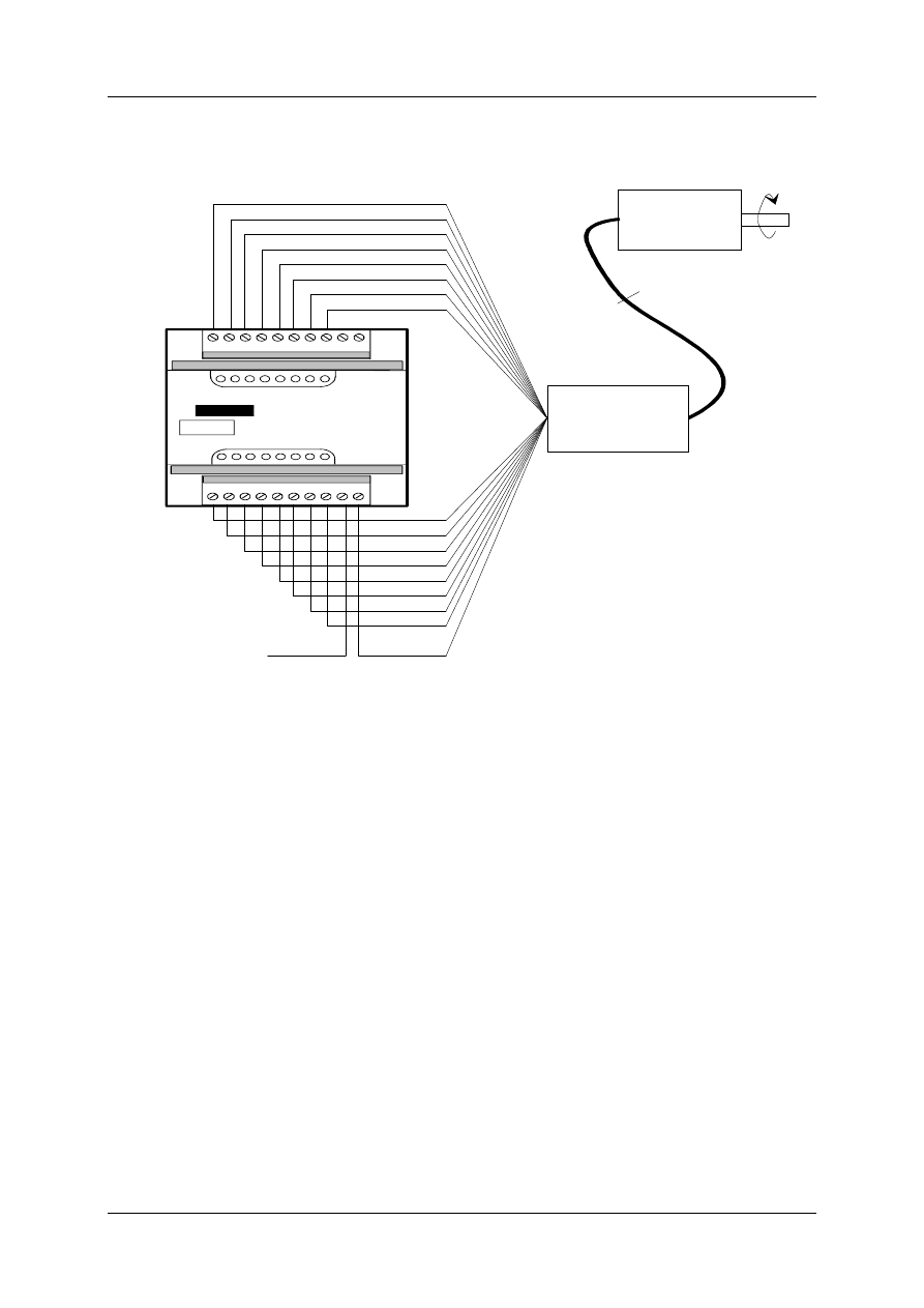
3.3.2 Absolute-Analogue-Encoder
The analogue inputs (U0, U1, U2) show a 12 bit resolution. The path can be resolved with
4095 increments. The inputs have a permanent configuration of 0...10 V (Figure 12).
24V0V
1 2 3
RS232
Power Supply
PS 4-401-MM2
2
1
SUCOnet K
U
0
U
1
U
2
I
0
I
1
I
2
U
10
U
11
U
12
0V
0V .0 .1 .2 .3 .0 .1 .2 24V 0V
Analog
Input
Digital
Input
Analogue
Output
Digital
Output
4
Actual-Position Axis 3 (0..10V)
Actual-Position Axis 2 (0..10V)
Actual-Position Axis 1 (0..10V)
Figure 12: Input Assignment for Absolute Analogue Encoder
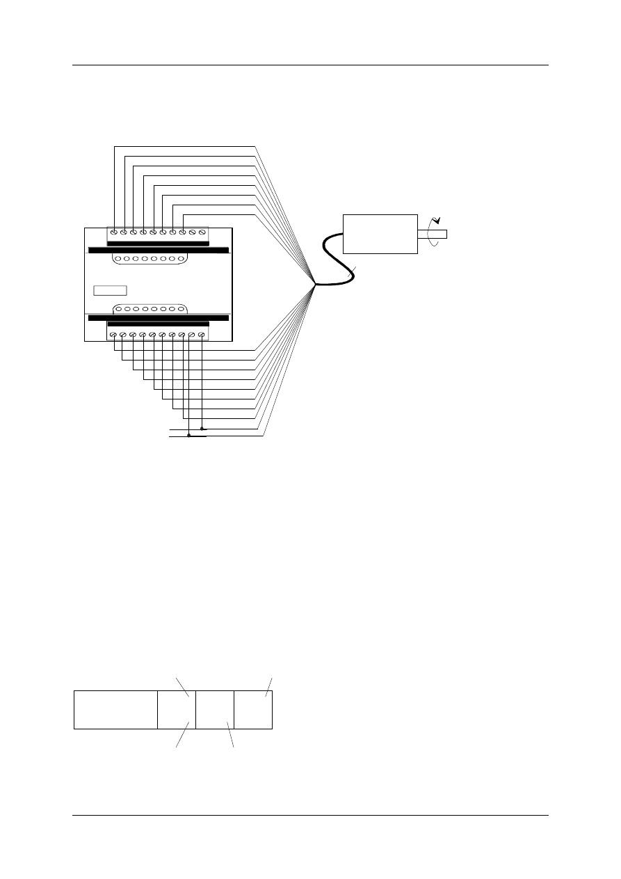
3.3.3 Incremental Encoder
Incremental encoder systems have, in comparison
with absolute encoder systems, a considerable cost
advantage. They are connected to the local
expansion module LE4-622-CX1. The encoder
signals must be 5V-TTL signals. In addition to both
signals, adjusted in 90° phases to each other (traces
A and B), the inverted signals must also be wired in
order to ensure detection of wire breakage. The zero
marker signal R and its inverted signal make an
exact increment referencing the axis (Figure 13).
The encoder must have an external supply of 5V.
The LE4-622-CX1 has internal quadrature decoding
of the encoder signals. An encoder resolution of 128
impulses per revolution produces an internal control
resolution of 512 impulses per revolution. A
parameter of once, twice or four times the amount
can be evaluated per axis.
The following Figure shows the wiring of two
incremental encoders to the LE4-622-CX1:
A
B
A
B
R
R
Impulse
Quad evaluation
_
_
_
Figure 13: Evaluation of the
Encoder Signals
Positioning Module ZB4-256-SP1
01/98 AWB-EM 27-1296-GB
15
SUCOcontrol
LE4-622-CX1
0V R B/D A/C R R B B A A
A A B B R R A/C B/D R 0V
Digital
Input
Digital
Input
Incremental-encoder 1
Incremental-encoder 2
-
-
-
-
-
-
+5V
0V
External
power supply
R
_
R
B
A
B
_
A
_
R
_
R
B
_
A
_
B
A
Figure 14: Wiring two Incremental-Encoders to the Local Expansion LE4-622-CX1
One reference signal is required per phase of each axis. It must ensure that the signal on the
PLC changes from 0 to 1 while crossing over the reference point. The reference point signal
should not change to 'zero' before the electrical limit switch is reached. This is the only
method to ensure correct referencing.
The reference point signals are read by a digital input on the LE (LE-116-DX1) module. This
LE
must be located to the right of the LE-counter (LE4-622-CX1).
An alternative to using 5V encoder signals for up to 300kHz signals is the option of using
24V encoder signals on the inputs R, Y, Z for signals up to 30kHz. For further information,
please refer to the LE4-622-CX1 specifications listed in the user manual: AWB 27-1263-GB).
3.3.4 Incremental-Digital Encoder
In the event that an LE-counter (LE4-622-CX1) can not be used to connect an incremental
encoder system, it is possible to switch the encoder signal with a level converter to provide
the correct voltage to the digital inputs of the local expansion module LE4-116-DX1. The
lowest bit must be switched over to the input I0 (Figure 15). The same requirements apply to
the reference switch signals as to the incremental encoder signals.
TIPS:
•
LE4-116-DX1 expansion units to which incremental-digital encoders are connected, must
be plugged directly into the CPU (bus position 1/2/3).
•
Referencing the increments can not be exact due to the lack of zero marker signal
processing. This problem is caused by the size of the operating range of the
reference point switch.
Positioning Module ZB4-256-SP1
01/98 AWB-EM 27-1296-GB
16
S U C O c o n t r o l
L E 4 - 1 1 6 - D X 1
. 0 . 1 . 2 . 3 . 4 . 5 . 6 . 7 0 V
. 8 . 9 . 1 0 . 1 1 . 1 2 . 1 3 . 1 4 . 1 5 2 4 V 0 V
D i g i t a l
I n p u t
D i g i t a l
I n p u t
I n c r e m e n t a l - e n c o d e r
D 7
D 6
D 5
D 4
D 3
D 2
D 1
D 0
D 1 5
D 1 4
D 1 3
D 1 2
D 1 1
D 1 0
D 9
D 8
G N D
A , A , B , B , C , C
-
-
-
C o n v e r t e r /
C o u n t e r
+ 2 4 V
Figure 15: Connection of an Incremental Encoder with a Parallel Interface (24V)
3.3.5 Encoder Signals via Field Bus Interface Suconet K
The positions can also be read in via Suconet K if positioning does not have to be exact or if
the axis has a low dynamic. The actual values of the position underlie a considerable dead
time for the position control due to the master PLC´s cycle period. This solution should
therefore only be used in special cases.
Programming example
The actual values for the axes 1 and 2 are read in by an absolute Suconet K1 compatible
encoder, e.g.: PS4-201-MM1 on the master PLC. The following programming instructions are
necessary in order to transmit the actual value to the positioning module:
00022 ACTVALUE
"Actual values transmitted via Suconet
001
L RDW1.3.0.0
Absolute-encoder axis 1
002
= SDW1.1.0.14
Actual-value axis 1
003
L RDW1.4.0.0
Absolute-encoder axis 2
004
= SDW1.1.0.16
Actual-value axis 2

Positioning Module ZB4-256-SP1
01/98 AWB-EM 27-1296-GB
17
TIPS:
•
Due to the absence of zero marker signal processing, it can not be exactly incrementally
referenced with this connection. This fault is caused by the size of the operating range of
the reference point switch.
•
Suconet K encoders must be configured as incremental axes. They can also be operated
as absolute axes. In this case the master PLC does not need to activate the reference
cycle for this axis.
3.4 Connecting Extra Digital Signals
The positioning module allows the enabling and disabling of axis movement via digital 24V
signals. These signals are connected to LE4-116-DD1. This LE has 8 digital inputs and 8
digital outputs. This LE must be connected to the right of the LE4-116-DX1, if present.
3.5 Suconet K Addressing
The slave-address is set with the aid of the DIP-switch S2 on the PS4-401-MM2 (S2.1=1).
The following coordinates to the Suconet K slave-addresses are valid:
Suconet K Slave-Address
2
3
4
5
6
7
8
...
31
DIP-Switch
2.2
0
1
0
1
0
1
0
...
1
2.3
1
1
0
0
1
1
0
...
1
2.4
0
0
1
1
1
1
0
...
1
2.5
0
0
0
0
0
0
1
...
1
2.6
0
0
0
0
0
0
0
...
1
T
I
P
:
T
h
e
D
I
P
s
w
i
t
c
h
2
.
1
m
u
s
t
b
e
i
n
p
o
s
i
t
i
o
n
1
,
i
n
o
r
d
e
r
t
o
a
c
t
i
v
a
t
e
s
e
t
a
d
d
r
e
s
s
e
s
.
A
c
h
a
n
g
e
d
a
d
d
r
e
s
s
p
o
s
i
t
i
o
n
i
s
a
c
t
i
v
a
t
e
d
a
f
t
e
r
a
p
o
w
e
r
c
y
c
l
i
n
g
t
h
e
P
L
C
.
Positioning Module ZB4-256-SP1
01/98 AWB-EM 27-1296-GB
18
4 Programming
The functions of the positioning module are completely controlled via field bus
communication. A protocol layer is filed above the Suconet K protocol, individual actions in
the positioning module are addressed with this protocol layer.
4.1 Communication
The communication of the positioning module, as a slave, in the Suconet K network with the
master PLC, based on the command from the master. The various Jobs consist of parameter
settings of the axis, transmission of Jobs, such as motion control (Figure 16).
Positioning-Slave
Suconet K
Master-PLC
Command
Axe data
Jobs
- Content
- Control
20 Byte
Status
Demand data
Quitting
Cyclical
Response
17 Byte
Figure 16: Communication Mechanism
The positioning module cyclically sends a status telegram, in which the status is sent as bit
code. A parameterized request data channel passes word-information
e. g. the momentary actual position and the actual lag error, to the master PLC.
4.2 Setting up the PLC Software
The positioning module is an example program for the Suconet K compatible compact PLC
PS4-201-MM1. The individual modules have the following Jobs:
MAIN.q42
Main program of the positioning module
I1POSMOD.q42
Sequencer of the positioning module and controlling the operating
modes.
I1JOBS00.q42
Communication driver to the Suconet K slave positioning module.
I1JOBS01.q42
Assignment of values to the individual internal Jobs,
assignment of the Jobs table.
I1PAR.q42
Assignment of the axis parameters.
I1APOS.q42
Example for automatic sequencer.
I1REFPARq42
Parameters for referencing
Positioning Module ZB4-256-SP1
01/98 AWB-EM 27-1296-GB
19
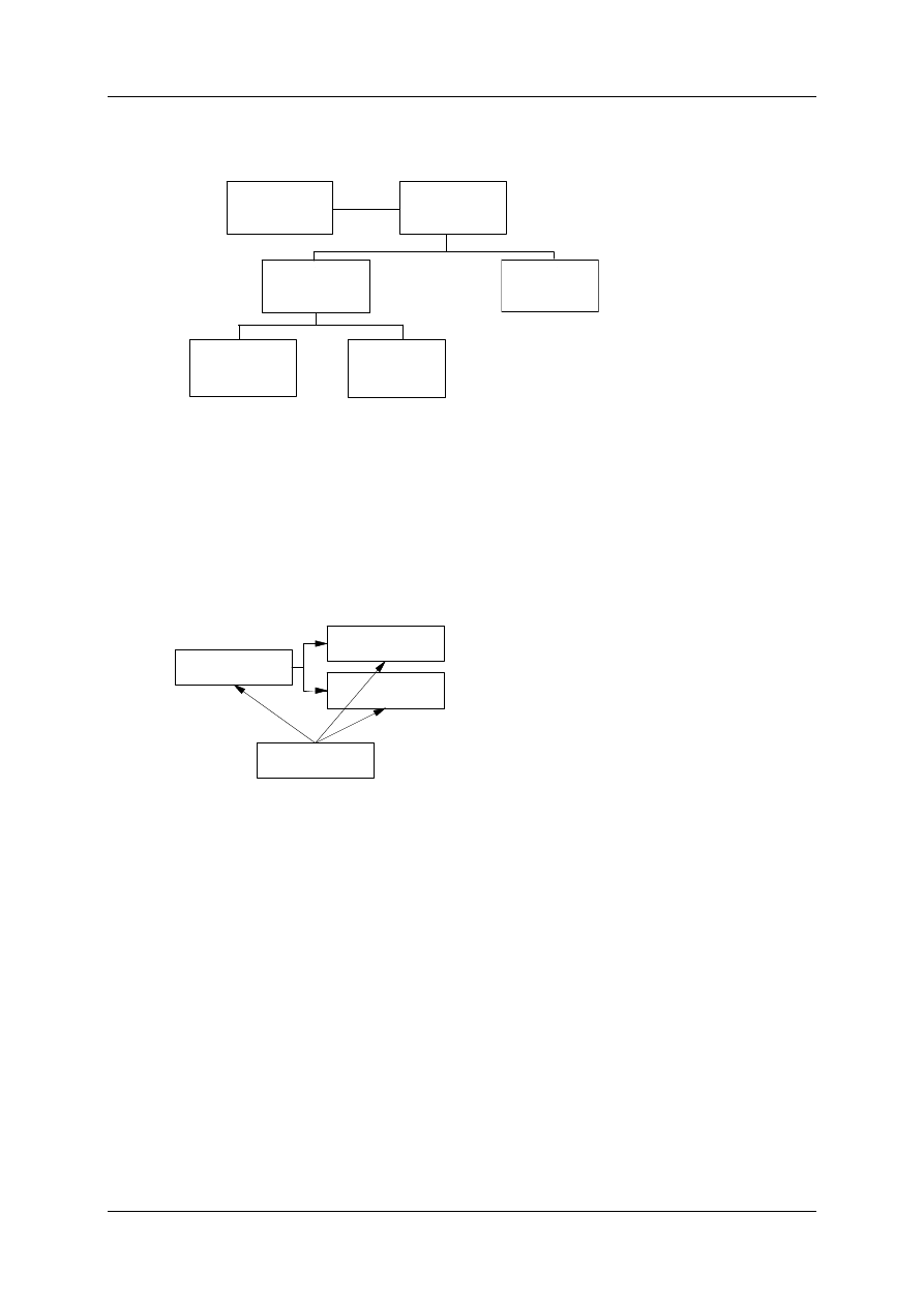
MAIN.q42
main program
I1APOS.q42
Automatic
Sequencer
I1JOBS00.q42
Communication
Driver
I1JOBS01.q42
Setting
Parameter for
Internal Jobs
I1PAR.q42
Axe data
Setting
Parameter
I1POSMOD.q42
sequential
control
Figure 17: PLC Program Structure
If more than one positioning module is connected to a master PLC, the individual program
modules are then named by increasing numbers. The # is used for this number in the
following Figure.
i#POSMOD.q42
i#JOBS00.q42
i#PAR.q42
i#POSMOD.z42
Figure 18: Module Structure of a Positioning module
The modules i#POSMOD.q42 are integrated in a superordinate main program in this
configuration. Up to 6 positioning modules can be linked to the PS4-201-MM1 according to
the limitations of the master PLC, specifically with regard to the number of slaves and the
limitations of the number of sent and received data for Suconet K. For three positioning
modules the software structure in the PLC would look as follows:

Positioning Module ZB4-256-SP1
01/98 AWB-EM 27-1296-GB
20
i1POSMOD.q42
i1JOBS00.q42
i1PAR.q42
i1POSMOD.z42
MAIN.q42
MAIN.z42
MAIN.k42
i2POSMOD.q42
i2JOBS00.q42
i2PAR.q42
i2POSMOD.z42
i3POSMOD.q42
i3JOBS00.q42
i3PAR.q42
i3POSMOD.z42
APOS.q42
Figure 19: Software Structure for three Positioning Modules
4.2.1 Symbolic Programming
All variables are symbolically programmed in the above mentioned modules. The name of
the variable was systematically built up as follows
1.
Letter: Type (X(bit, B(byte, W(word)
2.
Letter: Module number (1..6)
3.
Letter: M=user interface bit
3..8.
Letter: marking the variables
8.
Letter: 1..3 -> Axis number
4.3 Telegram structure
All telegrams which can be swapped between the master PLC and the positioning module
have a homogenous structure:
•
The content of the telegram and the task (Job-ID) are defined with byte 0 in the
commanding telegram. Due to this fact the contents of bytes 1..19 is dependant on the
Job-ID.
•
The cyclical response telegram of the positioning module has a fixed structure. The first
two words reproduce, the bit-coded condition of the individual axes. The next six words
consist of two demand data channels - the content of the channels can be parameterized.
In the last byte, the last received byte 0 is sent back negated. The confirmation between
the master PLC and the positioning module is realised with this byte.
The following Figure shows the schematic diagram of the telegrams for both directions:
Positioning Module ZB4-256-SP1
01/98 AWB-EM 27-1296-GB
21
Master PosMod
Byte 0 AX-Bits or Job-ID
Byte 1..19 ID-dependant
Data
PosMod Master
Wort 0 Status word 1
Wort 2 Status word 2
Wort 4..8 Channel 0
Wort 10..14 Channel 1
Byte 16 Quitting
Figure 20: Telegram structure
With the aid of status words one can react to the condition of each axis of the positioning
module in the PLC program. For instance, in the demo program an unset init-bit in the status
word_1 causes a down loading of the initialising telegram for the axis concerned. The
sequencing of the init-bit, which is sent back from the positioning module- causes the
changing of the axis parameters at any time and loads them into the positioning module. The
following program lines have been taken from the module I1POSMOD.Q42.
00005 CM-INIT "Calling up the Initialising-Jobs
001
LN
'X1INIT1
P1 AX1 Init-Flag
002
O
'X1MINIT1
P1 AX1-MMI Init
003
JCN
INITAX2
004
CM
$PAR1AX1
005
CM
$M1JOB1I
006
L K 0
007
= 'X1MINIT1
P1 AX1-MMI Init
008
= 'X1INIT
P1AX1 Init-Flag
009
= 'X1JREF1
P1AX1: Ref-Job-Flag
010
"Transfer a new internal Job
011
L K 0
012
=
'X1ITAB
P1 Transfer flag internal
Jobs TAB
013 = 'X1TRANSF P1 internal Jobs&TAB transferred
014
015
JP END_POS
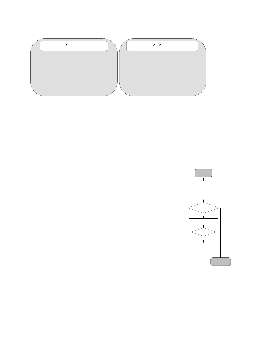
4.3.1 Commanding and Quitting
The communication between the master PLC and the
positioning module normally follows the structure as shown in
the flow diagram (Figure 21). After the status has been read a check is run-, to determine
whether the positioning module has received the last Job. When this is not the case, due to
the asynchronous cycles of both controllers, the program code, which could formulate the
new order (skip onto the label "Pos.-End"), is skipped. As soon as there has been an order to
quit, it is possible to formulate a new Job. This is dependant upon:
Pos_Start
PosMod-Answer
Status
Actual values
Quitting
Quit ?
ID0 - Telegram
IDx - Telegram
Pos_End
XM-xxx ?
OK
no
1
0
Figure 21: Sequence of Quitting
and Commanding
Positioning Module ZB4-256-SP1
01/98 AWB-EM 27-1296-GB
22
•
The status bits, which have been set by the positioning module in both status words,
or
•
The command bits from the machine’s sequential control - symbolised in the flow diagram
as "XM-xxx".
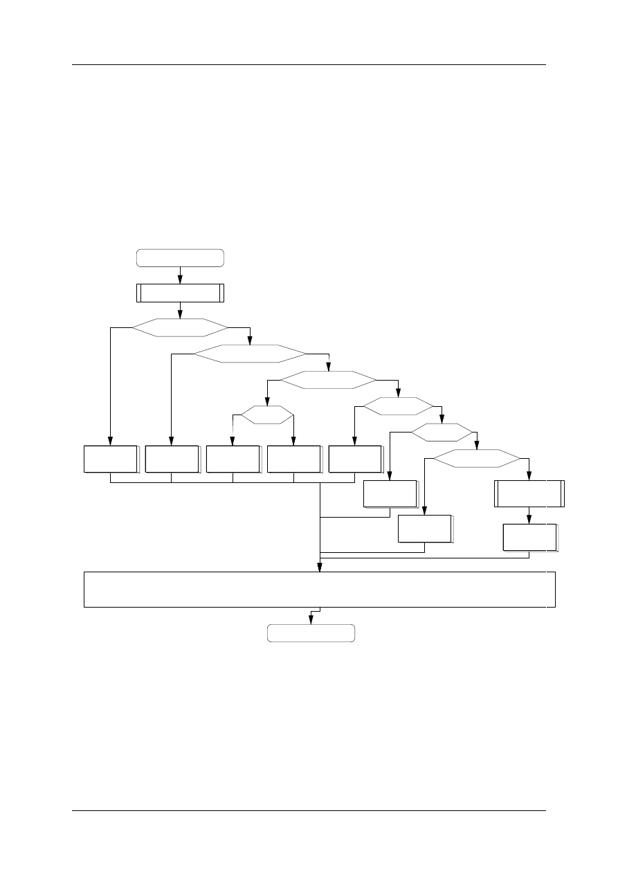
Complex sequences are very simple to implement. The following Figure shows the
sequence in which the axes are automatically initialised and released after starting the
system. Furthermore, the operating mode can be switched over between manual and
automatic, as often as wished.
InitAX-Flg
ID1
Init AX1
Contr. BB
BBBB BB
ID2
Contr. rele
BA Hand
Jog +
ID13
Jog+
ID14
Jog-
Stop
ID7
Stop
Start
ID6
Start
Abort
ID8
Abort
sequencerl
Automatic
ID5
order
Suconet K
Communication
Start
MMI
End
f
tr
f
tr
tr
tr
f
Figure 22: Sequential control
Positioning Module ZB4-256-SP1
01/98 AWB-EM 27-1296-GB
23
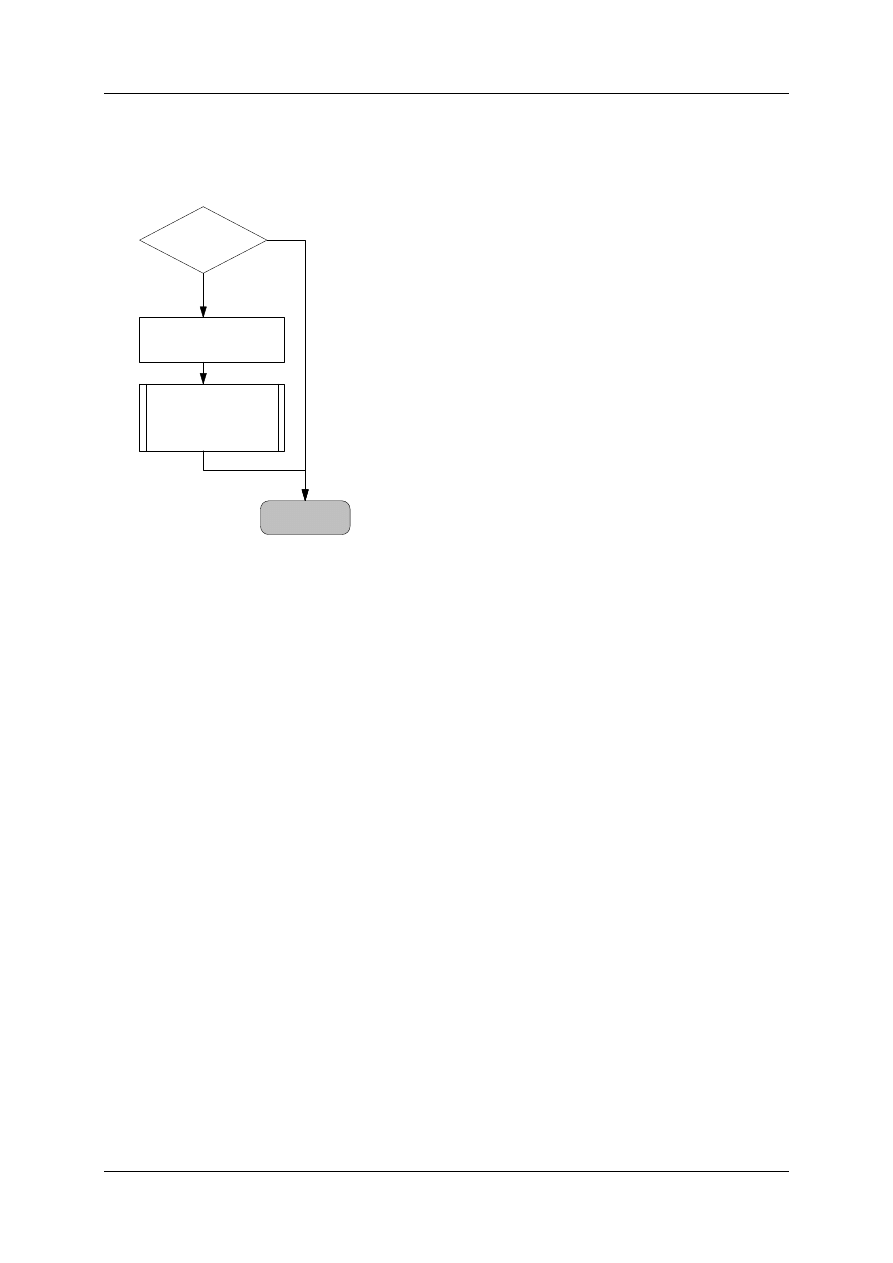
4.3.2 Job
After the initialisation and release of an axis the most
important command is the Job (Job-ID 5). A Job can
be given when the positioning of the previous Job has
been completed and stands within the In-Position
window. The above example illustrates this with the
help of the bit ´X1-AOK. The instructions for extending
the program are shown in the example programs
below. The Job is given when the axes are ready and
the ´X-RUN signal appears. This signal can be
produced either directly as a hardware signal (e. g.
proximity limit switch) or from the logical sequencing of
various signals.
4.4 Example for Successive Engineering of the Positioning Connection
The engineering in the master PLC can be explained with the use of a concrete example. A
positioning module is integrated and can be manually and automatically operated.
4.4.1 Integrating the Positioning Modules
The minimal main program which integrates the configuration of the devices and a
positioning module and calls up the positioning module, consists of very few program lines:
...
00002 POSMOD
"Calling up the individual positioning modules
001
"AX-bits are set to almost all three axes,
002
"must be transposed accordingly (ID2,6,7,8) as necessary
003
L KB 7
004
= 'B1AX P1 Ax-Bits
005
006
CM $M1POS
007
008
...
´X1-AOK
&
X_DRIVE?
´W1-ZPOs = 10000
bAXbits = 1
$JOB-5
CONTINUE
1
0
Figure 23: Job

Positioning Module ZB4-256-SP1
01/98 AWB-EM 27-1296-GB
24
4.4.2 Extending the Main Program with a User Interface
The main program can be extended with a user command interface with the MMI-bits per
positioning module. With the aid of the push-button I0.7 it can be ensured that during the
start up phase that the changed online axis data are resent to the positioning module. In the
example below, the push-button I0.5 sends the controller release for all axes. With the aid of
both push-buttons I0.1 and I0.2 the first axis of the first positioning module can be manually
operated.
...
00001 OPERATE "Jog initialising an axis during starting up
001
L I 0.7
Button: initialise axis
002
= 'X1MINIT1
P1 AX1-MMI Init
003
"releasing controller of all axes
004
L I 0.5
Button: MMI-initial position
005
= 'X1MINIT
P1 MMI: initial position
006
"manual drive of axis 1 in positive direction
007
L I 0.1
Button: AX1-Jog+
008
= 'X1MJOGP1
P1 MMI: AX1-Jog+
009
"manual drive of axis 1 in negative direction
010
L I 0.2
Button: AX1-Jog-
011
= 'X1MJOGM1
P1 MMI: AX1-Jog-
012
00002 POSMOD "calling up the individual positioning modules
001
"AX-bits are set onto almost all three axes
002
"must be transposed accordingly (ID2,6,7,8) as necessary
003
L KB 7
004
= 'B1AX
P1 Ax-Bits
005
006
CM $M1POS
007
008
...
4.4.3 Status-Bits of the Individual Positioning Modules
It is helpful to see all status bits (Init-Flag, controller ready, lag error, In-Position, etc.) on a
monitor, particularly during the start-up of the individual axes and positioning modules. The
status words 1 and 2 of the individual positioning modules can be copied onto free flag
words. With the aid of the LED the status of all axes can be easily monitored.
...
00004 STATUS1
"Status PosMod-1
001
L 'W1STAT1
P1 Status-Word 1
002
= MW100
003
L 'W1STAT2
P1 Status-Word 2
004
= MW102
005
006
...
The actual and target positions of the individual axes can either be seen in the modules
"!#POSMOD.q42" or must be loaded equivalent to the status bits in the module "MAIN.q42".

Positioning Module ZB4-256-SP1
01/98 AWB-EM 27-1296-GB
25
4.4.4 Generating a Job
Jobs can be generated in different ways:
•
sequencer global for all positioning modules
•
sequencer within individual positioning modules
•
individual commanding global
The following example shows how a Job can be individually set in the main program. All
axes can be included. The most important requirements for commanding an axis are:
•
the axis is ready to receive a Job: (´X#AOK1=1)
•
positioning module is ready (´X#READY=1)
In this example, axis 1 of the positioning module 1 should run to the fixed positions when the
digital input I0.0 arrives:
...
00003 RUN
"start Job
001
L I 0.0
Button: AX1 Job
002
JCN STATUS1
003
004
" transmit Job
005
L KB 1
006
= 'B1START
P1 JOB5: Record-Mode
007
L KW 22222
008
= 'W1ZPOS1
P1 JOB5: Target-Pos AX1
009
L KB 30
010
= 'B1VOVR1
P1 JOB5: Feed-Override AX1
011
L KB 1
012
= 'B1J5AX
P1 JOB5: AX-bits
013
014
L 'X1READY
P1 Commanding Flag (=1: ok)
015
A 'X1AOK1
P1 AX1: Job-Ready
016
= 'X1MJOB5
P1 MMI: Job5-Send flag
017
018
CM $M1JOB5
019
020
...

Positioning Module ZB4-256-SP1
01/98 AWB-EM 27-1296-GB
26
4.4.5 Automatic Sequencer Example
The module I1APOS.q42 is a good example how any axis can be automatically positioned.
The requirements for executing a sequence are: that all axes concerned with the Job are In-
Position, that all axes concerned have reached the end of the Job (´X#AOKi=1) and that the
positioning module is ready to dispatch a new order (´X#READY=1).
00000
$MAUTO
”Automatic-controlling with sequencer and JOB-5
001 SK0 -5
processing a record
002 [ ] S: K 1
003 [ ] R: 'XSKRES
004 [b] SINO:
005 [b] ERR:
006 [b] SQNO:
007 [ ] TG:
008 [$] INIT: $INITS
009 [$] AC1: $RECORD1
010 [$] AC2: $RECORD2
011 [$] AC3: $RECORD3
012 [$] AC4: $RECORD4
013 [$] AC5: $RECORD5
014
015 EM
016
00001 $INITS "Initialising Sequencer Automatic-Program """"""""""
001 L K 0
002 = 'XSKRES
003 L KB 1
004 = SK0 SINO
processing a record
005 EM
006
00002 $RECORD1
"Job 1 """"""""""""""""""""""""""""""""""""""""""""""""""
001 L 'X1AOK123
P1 AX123 Job ready
002 A 'X1READY
P1 commanding flag (=1: ok)
003 JCN END
004 L KB 1
005 = 'B1START
P1 JOB5: Record-Mode
006 L KW 1000
007 = 'W1ZPOS1
P1 JOB5: Target-Pos AX1
008 L KHB 8F
009 = 'B1VOVR1
P1 JOB5: Feed-Override AX1
010 L KB 1
011 = 'B1J5AX
P1 JOB5: AX-Bits
012 CM $M1JOB5
013 L KB 2
014 = SK0 SINO
processing a record
00003 END "
001 EM
002
003
00004 $RECORD2 "Job 2 """"""""""""""""""""""""""""""""""""""""""""""""""""
001 L 'X1AOK1
P1 AX1: Job-ready
002 A 'X1READY
P1 commanding flag (=1: ok)
003 JCN END
004 L KB 1
005 = 'B1START
P1 JOB5: Record-Mode
006 L KW 10000
007 = 'W1ZPOS1
P1 JOB5: Target-Pos AX1
008 L KHB 8F
009 = 'B1VOVR1
P1 JOB5: Feed-Override AX1
010 L KB 1
011 = 'B1J5AX
P1 JOB5: AX-Bits
012
013 CM $M1JOB5
014 L KB 3
015 = SK0 SINO
processing a record
00005 END "
001 EM
002

Positioning Module ZB4-256-SP1
01/98 AWB-EM 27-1296-GB
27
003
00006 $RECORD3 "Job 3 """"""""""""""""""""""""""""""""""""""""""""""""""""
001 L 'X1AOK1
P1 AX1: Job ready
002 A 'X1READY
P1 commanding flag (=1: ok)
003 JCN END
004 L KB 1
005 = 'B1START
P1 JOB5: Record-Mode
006 L KW 10000
007 = 'W1ZPOS1
P1 JOB5: Target-Pos AX1
008 L KHB F
009 = 'B1VOVR1
P1 JOB5: Feed-Override AX1
010 L KB 1
011 = 'B1J5AX
P1 JOB5: AX-Bits
012
013 CM $M1JOB5
014 L KB 4
015 = SK0 SINO
processing a record
00007 END "
001 EM
002
003
004
00008 $RECORD4 "Job 4 """"""""""""""""""""""""""""""""""""""""""""""""""""
001 L 'X1AOK1
P1 AX1: Job-ready
002 A 'X1READY
P1 commanding flag (=1: ok)
003 JCN END
004 L KB 1
005 = 'B1START
P1 JOB5: -Mode
006 L KW 20000
007 = 'W1ZPOS1
P1 JOB5: Target-Pos AX1
008 L KHB FF
009 = 'B1VOVR1
P1 JOB5: Feed-Override AX1
010 L KB 1
011 = 'B1J5AX
P1 JOB5: AX-Bits
012
013 CM $M1JOB5
014 L KB 5
015 = SK0 SINO
processing a record
00009 END "
001 EM
002
003
00010 $RECORD5 "Job 5 """"""""""""""""""""""""""""""""""""""""""""""""""""
001 L 'X1AOK1
P1 AX1: Job-ready
002 A 'X1READY
P1 commanding flag (=1: ok)
003 JCN END
004 L KB 1
005 = 'B1START
P1 JOB5: Line-Mode
006 L KW 3000
007 = 'W1ZPOS1
P1 JOB5: Target-Pos AX1
008 L KHB 2F
009 = 'B1VOVR1
P1 JOB5: Feed-Override AX1
010 L KB 1
011 = 'B1J5AX
P1 JOB5: AX-Bits
012
013 CM $M1JOB5
014 L KB 1
015 = SK0 SINO
processing a record
00011 END "
001 EM
002
003

Positioning Module ZB4-256-SP1
01/98 AWB-EM 27-1296-GB
28
4.5 Protocol
All telegrams for commanding the positioning module have a homogenous structure. An
order number (Job-ID) with a length of 5 bits (bit#0, #1, #2, #3, #4) is specified in the first
byte. The higher three bits (#5, #6, #7) characterise the axis concerned. Further data bytes
(words) follow depending on the order.
The commanding telegram
The positioning module responds cyclically, independent on the Job-ID of the master PLC,
with the following status telegram:
Byte
Bit
Name
State
Description
0
#0
Init-Axis 1
1
receiving the axis parameter data
#1
Init-Axis 2
1
receiving the axis parameter data
#2
Init-Axis 3
1
receiving the axis parameter data
#3
controller ready Axis 1
1
Servo amplifier indicates: controller ready
#4
controller ready Axis 2
1
Servo amplifier indicates: controller ready
#5
controller ready Axis 3
1
Servo amplifier indicates: controller ready
#6
Battery-Flag
1
no or dead battery
#7
Init-Flag
1
invalid initialising data from the master PLC
1
#0
neg. SWL Axis 1
1
neg. software-limit reached
#1
pos. SWELL Axis 1
1
pos. software-limit reached
#2
neg. SWL Axis 2
1
neg. software-limit reached
#3
pos. SWL Axis 2
1
pos. software-limit reached
#4
neg. SWL Axis 3
1
neg. software-limit reached
#5
pos. SWL Axis 3
1
pos. software-limit reached
#6
#7
Byte 0
Bit #0
Ä¿
Bit #1
|
Bit #2 | Job-ID (0..31)
Bit #3 |
Bit #4
ÄÙ
Bit #5
ÄÄ
Axis 1
Ä¿
Bit #6
ÄÄ
Axis 2 | as necessary
Bit #7
ÄÄ
Axis 3
ÄÙ
Byte 2 ..17 as necessary

Positioning Module ZB4-256-SP1
01/98 AWB-EM 27-1296-GB
29
2
#0
lag error Axis 1
1
exceeding the lag error
#1
lag error Axis 2
1
exceeding the lag error
#2
lag error Axis 3
1
exceeding the lag error
#3
#4
wire breakage Flag
1
wire breakage incremental encoder
#5
Reference point Axis 1
1
Referencing complete
#6
Reference point Axis 2
1
Referencing complete
#7
Reference point Axis 3
1
Referencing complete
3
#0
In-Pos.-Flag Axis 1
1
In-Position window reached
#1
In-Pos.-Flag Axis 2
1
In-Position window reached
#2
In-Pos.-Flag Axis 3
1
In-Position window reached
#3
End: Job Axis 1
1
Job completed
#4
End: Job Axis 2
1
Job completed
#5
End: Job Axis 3
1
Job completed
#6
Job-ready-Flag
Axis 1,2,3
1
AND-sequences: Bit #1 to #5
#7
internal Job-ready-Flag
1
internal Jobs completed
4&5
demand data channel
Block 1
actual-Position/lag error / set speed
axis 1
6&7
demand data channel
Block 1
actual-Position/lag error / set speed
axis 2
8&9
demand data channel
Block 1
actual-Position/lag error / set speed
axis 3
10&
11
demand data channel
Block 2
Target-Position/lag error/set speed/ current input I0/
voltage input U0/
Axis 1
12&
13
demand data channel
Block 2
Target-Position/lag error/set speed/ current input I0/
voltage input U0/
Axis 2
14&
15
demand data channel
Block 2
Target-Position/lag error/set speed/ current input I0/
voltage input U0/
Axis 3
16
Negation Byte 0
Quitting for Handshake
The master can influence the sequence control via these status messages (PS4-401-MM2 to
the master).

Positioning Module ZB4-256-SP1
01/98 AWB-EM 27-1296-GB
30
The status feedback have the following meanings:
Byte 0, Bit #0, #1, #2:
Init-AX1...3 is set when the axis parameter data block has
been received and processed. All further activities only
follow after a successful feedback of the init-bits.
Byte 0, #3, #4, #5:
Feedback when the connected servo amplifier has
set the signal 'controller ready' .
Providing that the controller has been released to the
corresponding servo amplifier with the Job-ID and that the
corresponding axis has been successfully initialised.
Byte 0, #6:
This bit shows the condition of the battery for the RAM buffer.
The bit is set when the battery is run down or not present.
Byte 0, #7:
The bit #7 is set while the corresponding Init-bit is not set,
when the master PLC has sent invalid initialising data for an
axis. Invalid axis data exist when one of the following
parameters has a value of 0:
•
rated speed
•
encoder resolution
•
maximum lag error
•
In-Position window
•
ramp-up time and
•
KV-Factor
Byte 1, Bit #0-#5:
The corresponding bit is set when one of the three axes
has reached the indication software-limits during a run
movement. The target point is internally set to the software-
limit. The software-limits are indicated with Job-ID1.
Byte 2, Bit #0, #1, #2:The corresponding bit is set and the axis is immediately
stopped (set value = 0V; QAW = 7FFF hex), when one of the
three axes exceeds the indicated maximum lag error
during a run movement. It is only possible to reset the lag
errors with Job-ID2.
Byte 2, Bit #4:
This bit registers a wire breakage on the encoder side. When a
wire breakage has been discovered in an axis, the positioning
module internally withdraws the release of the controller. The
recognition of a wire breakage is only possible with the LE4-
662-CX1 at this point.
Byte 2, Bit #5, #6, #7:An axis can be referenced when it possesses an
incremental encoder. With these bits, the successful completion
of a reference cycle, which has been commanded by Job-ID3,
is returned per axis.
Byte 3, Bit #0, #1, #2:The bits #0, #1 and #2 are set depending on the axis
when the indicated destination, within the In-Position window, is
reached. The In-Position windows volume of tolerance is
indicated per axis with the Job-ID1.
Byte 3, Bit #3, #4, #5:The corresponding bit is set depending on the axis,
after the Job has been successfully processed.
Byte 3, Bit #6:
This bit enables the AND relation of the Bits#0-#5 of byte 3.
Byte 3, Bit#7:
The corresponding bit is set depending on the axis, after the
internal Job has been successfully processed.

Positioning Module ZB4-256-SP1
01/98 AWB-EM 27-1296-GB
31
Word 4, 6, 8:
The parameter of the demand data channel-block 1 can
be set with the telegram controller release (Job-ID2). The actual
position, lag error or absolute set speed of each axis can be
indicated depending on the parameters.
Word 10, 12, 14:
The parameterization of the demand data channel-block 2 can
be set with the telegram controller release (Job-ID2). The target
positions of the last Job, jog-order, lag error or absolute set
speed of each axis or the values of the analogue power
(voltage) inputs can also be indicated depending on the
parameters.
Byte 16:
The first negated byte of the receiving telegram confirms the
order.
The following table gives an overall view of the implemented order of the telegrams (master
to PS4-401-MM2).
Job-
ID
Meaning
Job-ID Meaning
0
Zero-Job
17
AXi In-pos.-window
1
Initialising the axis parameters
18
2
Releases of the controller (synchronous)
19
3
Reference cycle AXi
20
line transmission
4
Job (=5)
21
selection of line + Start
5
Job (=4)
22
6
Start Job
23
7
Stop Job
24
8
Break Job
25
sequential proceeding and starting lines
9
Feed-Override
26
sequential and periodical proceeding
and starting lines
10
Absolute-speed
27
11
28
Transmitting the Job table
12
29
13
Jog AXi +
30
Setting the parameter of the demand
data channel
14
Jog AXi -
31
Controller releases (asynchronous)
15
16
Controlling AXi

Positioning Module ZB4-256-SP1
01/98 AWB-EM 27-1296-GB
32
4.5.1 Job-Zero (Job 00)
When programming the communication on the master PLC, it must be taken into
consideration that the commanding telegram stays so long in the master PLC's
communication memory until the contents of a new telegram has been saved. This means
that the positioning PLC reads and processes this telegram accordingly. Because of this, a
"ZERO-telegram" (Job-ID 00) should be sent after confirmation of the order.
Commanding telegram Job 00
Byte
Bit
Name
Indicatio
Meaning
0
Job and Axis recognition
0
Zero-Job is sent
When Job 00 in the positioning module has been successfully completed, the master
receives the following status telegram:
Status telegram
Byte
Bit
Name
State
Description
16
Negating Byte 0
FF Hex
Job 00 processed
4.5.2 Initialising Axis Parameter (Job 01)
Telegram: Axis Parameter
Byte 0
Bit #0..#4: JOB-ID = 1
Bit #5..#7: AX-Nr.(1..3)
Byte 1
ÄÄ
Parameter for configuring the type of axis and the encoder interface
Byte 2
Ä¿
encoder resolution (16 Bit)
Byte 3
ÄÙ
Byte 4
Ä¿
rated value (16-Bit)
Byte 5
ÄÙ
Byte 6
Ä¿
time constant (11 Bit, Bit#0..#10)
Byte 7
ÄÙ
#11
Multiplication factor time constant (0=1x, 1=10x)
#12
Analogue-output-factor (0=(+1)x, 1=(-1)x )
#13
actual value-counter direction (0=(+1)x, 1=(-1)x )
#14
#15
evaluation LE4-622-CX1
0
0
quadruple
1
0
double
0
1
single
Byte 8
Ä¿
Software-Limit - (16-Bit)
Byte 9
ÄÙ
Byte 10
Ä¿
Software-Limit + (16-Bit)
Byte 11
ÄÙ
Byte 12
Ä¿
maximum lag error (16-Bit)
Byte 13
ÄÙ
Byte 14
ÄÄ
In-Position window (8-Bit)
Byte 15
ÄÄ
KV-Factor (8-Bit)
Byte 16
ÄÄ
KG-Factor (8-Bit)
Byte 17
ÄÄ
KS-Factor (8-Bit)
Byte 18
ÄÄ
FS-Factor (8-Bit) window for Stick Slip
Byte 19
ÄÄ
KVSK-Factor (8-Bit) Scaling KV

Positioning Module ZB4-256-SP1
01/98 AWB-EM 27-1296-GB
33
The individual axes are initialised with this command. The commanding telegram must be
sent from the master to the positioning module once. The corresponding bit is set as return
information in Byte 0 of the response telegram. The initialisation can be sent as often as
necessary with, for example, a different KV-Factor. This does not interrupt an eventual
running axis.
The following example explains the commanding telegram Job 1.
Byte 0:
The Job-ID is entered in the bits #0-#4. The parameter of the axis to be
set is selected with bits #5, #6, #7.
Example:
21 Hex
Meaning:
Job 1 (bit #0) for axis 1 (bit #5) is called up in the positioning module.
Byte 1:
The parameter of the type of axis (master or slave axis) and the
encoder interface are set in byte 1. The type of axis is defined by bits
#0 and #1. The type of axis indicates how the set value indication for
the axis concerned succeeds.
The axis concerned is the master axis when both bits are at 0. The
master axis receives its own target position. The master axis is
specified when one of both bits #0, #1 are set. This axis is operated
synchronous to the previous master axis. The following conditions are
to be followed:
Axis 1 can only be operated as a master axis.
Axis 2 can only be operated synchronous to axis 1.
Axis 3 can be operated synchronous to either axis 1 or 2.

Positioning Module ZB4-256-SP1
01/98 AWB-EM 27-1296-GB
34
Parameterization of the type of axis and of the encoder interface byte 1
Bit #2:
Defining the encoder types (incremental or absolute)
Bit #3, #4:
Defining the encoder connection.
Byte 1
master axis recognition
Bit #0
0
1
0
Bit #1
0
0
1
|
|
|
|
|
synchronisation with axis 2 (only Axis 3)
|
synchronisation with Axis 1 (Axes 2 u. 3)
master axis (no synchronisation control)
Absolute / increment. encoder
Bit #2
= 0
incremental encoder
= 1
absolute encoder
Connecting the encoder
Bit #3
0
1
|
|
|
Bit #2=0: Suconet K
|
Bit #2=1: absolute-digital encoder
Bit #2=0: LE4- connecting the incremental-encoder
Bit #2=1: absolute-analogue encoder
Bit #4
0
1
|
|
|
Bit #2=0: wired parallel to LE4-116-DX1
|
Bit #2=1: wired parallel to LE4-116-DX1
Bit #2=0: LE4-622-CX1
Bit #2=1: SSI-Interface (LE4-xxx-SX1)
binary or Gray-Code
Bit #5
0
1
|
|
|
Bit #2=0: Incremental encoder, 24V (LE4-622-CX1)
|
Bit #2=1: absolute Gray-Code (LE4-116-DX1)
Bit #2=0: Incremental encoder, 5V TTL (LE4-622-CX1)
Bit #2=1: absolute binary (LE4-116-DX1)
Hardware Input
Bit #6
1
0
1
0
Bit #7
1
0
0
1
|
|
|
|
|
|
|
Bit #2=0, Bit #3=0, Bit #4=0:
|
|
|
Port 1 2.LE4-622-CX1
|
|
|
Bit #2=0, Bit #3=0, Bit #4=1: 3. LE4-116-DX1
|
|
|
Bit #2=1, Bit #3=0: U2
|
|
|
Bit #2=1, Bit #3=1, Bit #4=0: Port3 LE4-xxx-SX1
|
|
|
Bit #2=1, Bit #3=1, Bit #4=1: 3. LE4-116-DX1
|
|
Bit #2=0, Bit #3=0, Bit #4=0: Port2 1. LE4-622-CX1
|
|
Bit #2=0, Bit #3=0, Bit #4=1: 2. LE4-116-DX1
|
|
Bit #2=1, Bit #3=0: U1
|
|
Bit #2=1, Bit #3=1, Bit #4=0: Port2 1. LE4-xxx-SX1
|
|
Bit #2=1, Bit #3=1, Bit #4=1: 2. LE4-116-DX1
|
Bit #2=0, Bit #3=0, Bit #4=0: Port1 1. LE4-622-CX1
|
Bit #2=0, Bit #3=0, Bit #4=1: 1. LE4-116-DX1
|
Bit #2=1, Bit #3=0: U0
|
Bit #2=1, Bit #3=1, Bit #4=0: Port1 LE4-xxx-SX1
|
Bit #2=1, Bit #3=1, Bit #4=1: 1. LE4-116-DX1
Test-Mode (incremental & absolute Axes)

Positioning Module ZB4-256-SP1
01/98 AWB-EM 27-1296-GB
35
Both analogue (bit #3=0) and digital (bit3=1) encoders can be
used with absolute encoders. Absolute-digital encoders are
connected via SSI-interface (is currently not supported) or wired
parallel (bit #4=1) to one another. Incremental encoder (bit
#2=0) can be wired either parallel onto LE4-116-DX1 (Bit #3=0
and Bit#4=1) or directly onto a counter channel LE4-622-CX1
(bit #3=0 and bit #4=0). A further wiring possibility is to read in
the position actual values via Suconet K from the master (bit
#3=1).
Note:
This axis can be referenced with Job-ID 3 when the position actual
value of the axis is read in via Suconet K. Absolute axes which are read in via
Suconet K must be configured as incremental axes.
Bit #5 - absolute-digital encoder systems (#2=1): Definition of coding
Bit #5=0
Position actual values are processed in
binary-code.
Bit #5=1
Position actual values are processed in
gray-code.
Bit #5 - incremental encoder systems to LE4-622-CX1 (#2=#4=0):
Defining the voltage interface
Bit #5=0
5V
Bit #5=1
24V
Bits #6, #7
Definition of the hardware-input, on these the axis
concerned reads in its encoder signals.
Note test mode:
The test mode for the corresponding axis is active when
the bits #6 and #7 are in position 1. The test mode allows a
complete function test of the positioning module without an
encoder. The maximum lag error in this type of operation is
proportional to the maximum reachable speed. Monitoring the
lag error in this type of operation remains active.
The machine zero point (ID 2) must be set to 0!
The following table illustrates the possible parameterization of master-axes.
Type of encoder
Connecting
Coding
Hardware-Inputs
Configuring bytes
Absolute
parallel
Gray coded
1. LE4-116-DX1
0011.1100 = 3C
hex
2. LE4-116-DX1
0111.1100 = 7C
hex
3. LE4-116-DX1
1011.1100 = BC
hex
binary
1. LE4-116-DX1
0001.1100 = 1C
hex
2. LE4-116-DX1
0101.1100 = 5C
hex
3. LE4-116-DX1
1001.1100 = 9C
hex

Positioning Module ZB4-256-SP1
01/98 AWB-EM 27-1296-GB
36
Type of encoder
Connecting
Coding
Hardware-Inputs
Configuring bytes
analogue
binary
U
0
0000.0100 = 04
hex
U
1
0100.0100 = 44
hex
U
2
1000.0100 = 84
hex
incremental
parallel
binary
1. LE4-116-DX1
0001.0000 = 10
hex
2. LE4-116-DX1
0101.0000 = 50
hex
3. LE4-116-DX1
1001.0000 = 90
hex
Suconet K
binary
AX1: SDWx.x.0.14
0000.1000 = 08
hex
AX2: SDWx.x.0.16
0000.1000 = 08
hex
AX3: SDWx.x.0.18
0000.1000 = 08
hex
5V,
1. LE4-622-CX1, K0
0000.0000 = 00
hex
A,A*,B,B*,
1. LE4-622-CX1, K1
0100.0000 = 40
hex
C,C*
2. LE4-622-CX1, K0
1000.0000 = 80
hex
24V,
1. LE4-622-CX1, K0
0010.0000 = 20
hex
R, Y, Z
1. LE4-622-CX1, K1
0110.0000 = 60
hex
2. LE4-622-CX1, K0
1010.0000 = A0
hex
Byte 1
Example:
1C Hex
Meaning:
•
The selected axis is the master axis (Bit#0, #1).
•
The actual values are read in via an absolute encoder (Bit #2).
•
The connection of the encoder is absolute-digital, wired parallel and is
hooked up to the LE4-116-DX1 (Bit #3, #4).
•
The actual values are read as binary code.
•
The actual value is read in from the first local expansion LE4-116-DX1 (Bit
#6, #7).
Byte 2 & 3:
The resolution of the encoder per motor revolution. Impulse multiplication
must be considered when using incremental encoders.
Byte 4 & 5:
Rated speed of the motor in revolutions per minute.
Byte 6 & 7:
Bit #0...#10 (11-bit-format) drive ramp-up time. The time constant (ramp-up
time = th) of the drive indicates the time span in milliseconds, in which the
drive should accelerate to the above mentioned rated speed. The maximum
acceleration of the axis, which is not exceeded during the movement is
indicated with the time constant.
Note:
The double ramp-up time should be entered as a principal value.
Bit #11: Multiplication factor of the ramp-up time. The ramp-up time for #11=0
is indicated in ms (tH
max
=2095ms=2.095s). The ramp-up time for
#11=1 is indicated in ms x 10 (tH
max
=20950ms=20.95s).
Bit #12: The sign of the analogue output can be controlled by this bit. In the
case of the analogue outputs and the encoder counting direction

Positioning Module ZB4-256-SP1
01/98 AWB-EM 27-1296-GB
37
signs being set in opposing positions, this can be adapted by this bit
without an electrical intervention.
Bit #13: The counting direction of an analogue or digital encoder can be
reversed by this bit.
TIP: The bits #12 and #13 must be set in order to swap the axis of the
counting direction in the correct sign position.
Bit #14 and #15: Defaulting the multiplication of impulse during the using of
incremental encoders to LE4-622-CX1.
Byte 8 & 9:
The value, software-limit minus, has the same function as the software-final
terminal switch left and is constantly monitored within the position control. The
target position is set internally to the software-limit, when the target position of
the axis lies below this value. The bit concerned is set in byte #2 of the
response telegram, when the axis reaches this modified target position.
Byte 10 &11: The value, software-limit plus, Byte #10 and #11 has the function as the
software-final terminal switch right and is constantly monitored within the
position control. The target position is set internally onto the software-limit,
when the target position of the axis exceeds this value. The bit concerned is
set in byte #2 of the response telegram, when the axis reaches this modified
target position.
Byte 12 & 13: The positioning module monitors the lag distance within the position control.
The lag distance is the difference between the momentary set and actual
position. A fatal axis error occurs (e. g. an axis has collided with an
obstruction) when the lag distance exceeds the maximum lag error. In this
case the axis is immediately switched off (the release of the controller is
retracted) and the set value of the speed is set to 0 V. The bit concerned is set
in byte 2 of the response telegram.
Byte 14:
With the aid of the In-Position window it can be determined, when the axis has
reached its indicated target. The bit concerned is set in byte 3 of the response
telegram, as soon as the actual position of the axis reaches the inside of the
window.
Byte 15:
The KV-Factor defines the reinforcement of the position control loop. The
bigger the KV-Factor, the stronger the position controls’ reaction to the
position deviation of the axis. Here, the lag error is dependant directly on the
adjusted KV-Factor. When the KV-Factors are too large, it can result in
instability of the position control loop (swaying).
Byte 16:
The lag error can be reduced when the momentary set value of the speed is
modulated to the position control. In order to reach this, a reinforcement
between 0 and 1 for the modulation must be indicated. Byte 16 defines the
counter of the KG for the speed reinforcement factor. This value is divided
internally by 255. The modulation of the speed is deactivated, when the
counter has a value of 0.
Byte 17:
Extreme Stick-Slip-effects (transition between grip- and glide friction) appears
when using servo-hydraulic drives (unlike electrical servo drives). The KS-
Factor in the position controller can be activated in order to compensate for
the so called Stick-Slip-effect. The KS-Factor defaults the necessary voltage,
in order to bring the hydraulic drive away from the grip friction. The position
controller emits 5 V for KS=255. The compensation of the Stick-Slip-effect is
inactive when KS=0.

Positioning Module ZB4-256-SP1
01/98 AWB-EM 27-1296-GB
38
Byte 18:
The sensitivity of the Stick-Slip-factor is adjusted to the parameter window
Stick-Slip. The indication value should be 2. A higher value results in an
increased sensitivity.
Byte 19:
The parameter KVSK scales the controller reinforcement in a positive or
negative area. An asymmetrical behaviour of e. g. hydraulic cylinders can be
levelled out specifically in this way, due to various piston surfaces. Bit #7
determines for which signal the KV should be enlarged (#7=0: negative KV,
#7=1: positive KV). The bits #0 to #6 indicate the factor. The KV is
symmetrical for byte 19 = 0. The negative KV is twice as big as the positive
one for byte 19 = 127. The same applies to the Stick-Slip-factor KS.
TIPS:
•
The initialising telegram must be sent separately for each axis.
•
The parameters encoder resolution, rated speed and ramp-up time should not be altered
during an axis movement.

Positioning Module ZB4-256-SP1
01/98 AWB-EM 27-1296-GB
39
4.5.3 Releasing the Controller (synchronous) (Job 02)
If the initialisation (Job 01) is successfully completed, the controller can then be released to
the servo amplifier of the relevant axis. Axes to be released, must be indicated in the
commanding telegram. A zero point alteration of the axes 1 to 3 (compare chapter 6.3.1)
can be indicated through bytes 2-7 in the commanding telegram. The momentary actual-
positions of the axes selected by the bits #5. #6, #7 (byte 0) are set as new target positions
when the positioning module receives the commanding telegram. As soon as the signal
“controller ready“ of the given servo amplifier appears, the position control for the released
axes is activated.
Unlike the asynchronous controller release (Job 31), the controller release effects a released
axis like a reset. All faulty conditions are reset for this axis.
The controller release for one or more axes can be retracted with the commanding telegram.
The positioning module then emits zero volt for the axis concerned to the analogue output.
TIPS:
•
The signal of the controller release (digital output QX0-2) must be linked to controller
ready (digital input IX0-2) in test-mode.
•
The zero point alteration must be zero with an axis operated in test mode.
•
The zero point alteration must be larger than the negative software-limit and smaller than
the positive software-limit, with an axis with incremental encoder.
•
The zero point alteration should not be changed on-line with an incremental axis!
Commanding telegram Job 02
Byte
Bit
Name
Example
Meaning
0
#0-4
Job-ID
2
Job 02
#5
Axis 1
1
controller release for the
#6
Axis 2
1
axes 1-3 requested
#7
Axis 3
1
Sum Byte 0
E2 Hex
2
Zero point alteration
0
no Zero point alteration
3
Axis 1
4
Zero point alteration
0
no Zero point alteration
5
Axis 2
6
Zero point alteration
0
no Zero point alteration
7
Axis 3
8
#0
Demand data channel
0
#1
0
#2
0
#3
0

Positioning Module ZB4-256-SP1
01/98 AWB-EM 27-1296-GB
40
#4
0
#5
0
#6
0
#7
x
Sum Byte 8
0
The demand data channel of the cyclical status telegram is configured by byte 8.
Bit
Channel 1 (Word 4..8)
#0
#1
#2
#3
#4
#5
#6
Channel 2 (Word 9..14)
0
0
x
x
x
x
x
K1: actual position Axes 1..3
1
0
x
x
x
x
x
K1: lag error of the Axes 1..3
0
1
x
x
x
x
x
K1: set speed of the Axes 1..3 (in reference to a 65535 th
part of the rated value)
x
x
0
0
0
0
0
K2: Target position of the Axes 1..3
x
x
1
0
0
0
0
K2: Lag error of the Axes 1..3
x
x
0
1
0
0
0
K2: Set speed of the Axes 1..3 (in reference to a 65535 th
part of the rated value)
x
x
0
0
1
0
0
K2: Analogue power inputs 0..20mA (12 Bit)
x
x
0
0
0
1
0
K2: Analogue voltage inputs 0..10V (12 Bit)
x
x
0
0
0
0
1
K2: Analogue voltage outputs ±10V (12 Bit)
The demand data channel can always be parameterized with Job 30 (setting the parameter
of the demand data channel) in order to e. g. switch the text display.
4.5.4 Referencing (Job 03)
Each incremental axis must be referenced because the position of the axis is unknown after
switching on. The reference cycle runs in several cycles within the positioning module. The
commanding telegram referencing (Job 03) sets the parameters of this internal sequence.
Attention:
Only one axis can be referenced with a commanding telegram Job 03.

Positioning Module ZB4-256-SP1
01/98 AWB-EM 27-1296-GB
41
Commanding telegram Job 03
Byte
Bit
Name
Example Meaning
0
#0-4
Job-ID
3
Job 03
#5
Axis 1
0
#6
Axis 2
0
Referencing Axis 3
#7
Axis 3
1
Sum Byte 0
83 Hex
1
Reference cam Search
direction
(0= negative, 1= positive)
1
positive search direction
2
Absolute search speed of
7F Hex
Absolute speed.: 50%
3
reference cam
4
Number of local expansion
(LE-116-DX1), to which the
reference cam signals are
switched (0-5)
5
LE-Nr. 5
5
Bit mask for reference cams
to be read in
1
first digital input
6
Absolute speed for zero
1F
Absolute speed zero marker
7
marker search
search: 50%
8
encoder resolution
1024
Increments per rev.
9
Byte 0:
The axes to be referenced are defined in the bits 5, 6 and 7.
Byte 1:
Byte 1 defines the search direction of the axis of the reference point switch.
Byte 1 = 0:
negative search direction
Byte 1 = 1:
positive search direction
Byte 2 & 3:
The speed with which the axis searches the reference point switch is indicated as the
absolute speed. The speed-override is internally set to 100% and can be changed at
any time during the search process with the Job-09 (Feed-Override).
Byte 4:
The reference point switch is read in to the local expansion module LE4-116-DX1. Byte
4 indicates the LE-number of the specified LE. The reference point signal is hooked up
to this LE. The local extensions are counted from 0 to 5.
Byte 5:
The digital reference point signal is specified on the LE-input over a bit mask.
Byte 6 & 7:
After receiving the signal from the reference point switch, the positioning controller
(PS4-401-MM2) reverses the axis and searches for the measurement system's zero
marking signal after leaving the reference point switch. The search speed of the zero
marker signal is indicated in bytes 6 and 7 as an absolute speed.

Positioning Module ZB4-256-SP1
01/98 AWB-EM 27-1296-GB
42
Byte 8 & 9:
The distance (after leaving the reference point switch) within which the zero marker
signal is searched. The encoder resolution should be registered here. Because of
internal automatic impulse multiplication, the encoder resolution must be multiplied by
four when using the LE4-622-CX1.
If the reference process of the axis is successfully completed, it is then replied in the bytes #5 to #7 in
byte 2 of the cyclical status telegram.
Status telegram
Byte
Bit
Name
State
Description
2
#5
Reference point-Axis 1
1
Referencing complete
#6
Reference point-Axis 2
1
Referencing complete
#7
Reference point-Axis 3
1
Referencing complete
Sequence of the referencing process (compare Figure 24)
As soon as the commanding telegram (Job-03) is received, the positioning module generates
an internal Job. The target position of the reference axis is set depending on the indicated
reference point search direction to one of the software-limits:
negative search direction :
actual value = positive software-limit
positive search direction :
actual value = negative software-limit
The selected target position is approached with the reference point search speed (rapid
feed).The movement is stopped as soon as the reference point signal appears. The axis then
moves with the marker search speed (creep feed) to the position, where the reference point
switch signal has changed from 0 to 1.
The axis searches the marker signal of the measuring system with the marker search speed
(creep feed), when connecting the encoder signals to the LE4-622-CX1. This signal must
appear within the encoder resolution. With rotary incremental encoders, this means: The
marker signal comes within 360°. The machine zero point is fixed when the marking signal
has been recognised. At this point, the actual position is set to the value which is transmitted
as a zero point alteration for the referenced axis, during the controller release. The bit
concerned is set in byte 3 of the status telegram and the axis can be commanded in further
sequences with the commands (Job-ID 5, 13, 14, 25 and 26).
With the connection variants "incremental parallel" and Suconet K, the positioning module
places the zero point offset onto the target position which lies as far as the reference
distance (byte 8 & 9) from the switch point of the reference switch in the opposite direction
to the reference direction.
The following Figure illustrates the reference cycle.
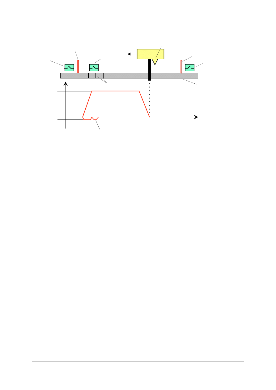
Positioning Module ZB4-256-SP1
01/98 AWB-EM 27-1296-GB
43
switch flag
pos. Software Limit
pos. terminal switch
incremental
measuring system
route
ref. point switch
neg. Software limit
neg. terminal switch
speed
vRef
vmarker
machine zero point
marker
Figure 24: Reference point-Starting cycle
If the axis receives a telegram "Referencing" while in the reference switch position (reference
switch signal = 1), then the axis runs towards the reference switch search direction until the
reference switch signal changes from 1 to 0. It brakes and reverses in order to approach the
position of the reference switch. The axis then runs an encoder resolution, in order to search
for the marker.
TIPS:
•
The reference point switch must be a contact. An inductive proximity limit switch must be
used, in order to minimise the inaccuracy of the reference point detection.
•
The reference point switch should have ample distance to the software-limit (approx. 1,5
x braking distance).
•
The reference point switch must remain at position 1, until the electrical terminal switch.
•
If detection of the marker can not be exact, the incremental encoder reference point
switch can be slightly shifted so that the marker indicates a distance of approx. 0.5
x encoder resolution x 4.0 to a max. of 1.0 x encoder resolution x 4.0 .
•
An incremental axis must indicate a zero point alteration that is larger than the negative
and smaller than the positive software-limit.

Positioning Module ZB4-256-SP1
01/98 AWB-EM 27-1296-GB
44
4.5.5 Job 04/05
Commanding telegram Job 04/05
Byte
Bit
Name
Example
Meaning
0
#0-4
Job-ID
5
Job 04/05
#5
Axis 1 - Job bit
1
Job for Axis 1
#6
Axis 2 - Job bit
1
Job for Axis 2
0
#7
Axis 3 - Job bit
0
Job for Axis 3
Sum Byte 0
65 Hex
1
#0
Start immediately
1
Start Job immediately
#1
Start: LE4-116-DD1= Byte 11
0
#2
Line end: LE4-116-DD1= Byte 12
0
#3
Line start: ReSet LE4-116-DD1=
Byte 13
0
Sum Byte 1
01 Hex
2
16-Bit Target position Axis 1
7FFF
Target position Axis 1:
3
Hex
7FFF Digits
4
16-Bit Target position Axis 2
1FF
Target position Axis 2:
5
Hex
1FF Digits
6
16-Bit Target position Axis 3
FF00
Target position Axis 3:
7
Hex
FF00 Digits
8
Feed-Override Axis 1
FF Hex
100%
9
Feed-Override Axis 2
FF Hex
100%
10
Feed-Override Axis 3
FF Hex
100%
11
Line-Start-Mask
(read LE-116-DD1)
0
inactive
12
Line-End-Mask
(set LE-116-DD1)
0
inactive
13
Reset-Mask
(write LE-116-DD1)
0
inactive

Positioning Module ZB4-256-SP1
01/98 AWB-EM 27-1296-GB
45
Two different Job-ID´s should be referred to this order. They are distinguished by Bit#0 of
Byte 0. If this bit is toggled in the master PLC's communication routine, the Jobs with short
routes can be permanently issued without Job-ID 0, without losing a Job.
Byte 1:
Defaults the start and target conditions of the Job.
Bit #0 = 1:
The Job is executed immediately. Otherwise the Bit #1 must be set or
the Job start must be initiated by Job-ID 6.
Bit #1 = 1:
The Job is started when the bit mask has been transmitted into Byte 11
and is set to the input of the optionally connected LE’s (LE4-116-DD1).
This start mechanism allows rapid synchronisation between movement
and machines.
Bit #2 = 1:
As soon as the Job has been completed (when all axes are in position
and have reached the end of the line) the indicated bit pattern in byte
12 is omitted onto the LE4-116-DD1. The byte mask is sequenced with
pre-set bits OR.
Bit #3 = 1:
As soon as an order is started, the set outputs on the LE4-116-DD1
can be deleted with the indicated bit mask in byte 13.
Byte 2 & 3:
Target position of axis 1
Byte 4 & 5:
Target position of axis 2
Byte 6 & 7:
Target position of axis 3
Byte 8, 9, 10:
These bytes indicate the axis related, percent of max. speed with which
individual axes approach their target points. The indication 255 [Digit]
equals 100 % and means that the axis is trying to reach the target with
max. speed. Depending on the distance between the start and target
position of the axis, the axis reaches max. speed or must first start to
brake in order to reach the exact target position. The motion speed can be
altered with the telegram "Feed-Override" (Job 09) at any time. The max.
speed depends on the actual programmed absolute speed of the axis.
This can also be changed with the telegram "absolute speed" (Job-ID 10)
at any time.
Byte 11:
Line-start mask
The start mask is compared with the bit mask, which is read in from the
LE4-116-DD1. The Job is initiated when they comply with one another.
Byte 12:
Line-end mask
The line-end mask is issued after a Job has been completed, on the LE4-
116-DD1 and OR-sequenced with a bits that have already been released.
Byte 13:
ReSet mask
Bits can only be set with the line-end mask. The reset mask can be
activated in order to specifically delete them. The preset bits are AND-
sequenced with this bit i. e., bits that have not been set in the reset mask
delete the set outputs on the LE4-116-DD1.
The positioning module distinguishes between internal and external Jobs and jog-
commands.
External Jobs:
Jobs are sent from the master to the positioning module.
Internal Jobs:
Jobs are internally filed in the positioning module. These internal Jobs are
managed by the following Jobs.

Positioning Module ZB4-256-SP1
01/98 AWB-EM 27-1296-GB
46
Job 20:
Internal run order transmission.
Job 21:
Selection of an internal Job and start.
Job 25:
Start command: processing internal sequential Jobs.
Job 26:
Start command: processing internal sequential periodic Jobs.
Job 28:
Execution sequence of the internal Jobs.
The advantage of the internal Jobs is the net cycle time independent execution of the
reoccurring Jobs.
The jog-commands (Job 13 and Job 14) are a special form of Jobs. They are executed
immediately.
4.5.6 Start Job (Job 06)
A Job previously sent with Job-ID 5 can be internally started with this telegram when this Job
has previously been stopped through "stop Job" (Job-ID 7). This also applies to internal Jobs
(Job-ID 25 or 26).
The bits #5..#7 can specify the axes which have to be started with this Job.
Telegram:
Start Job
4.5.7 Stop Job (Job 07)
A running Job (Job-ID 5, 25, 26) can be stopped at any time. In the course of this the axes
specified with the bits #5..#7 slow down to the new target speed = 0. The telegram "start
Job" enables a further execution of the stopped Job. The axes accelerate the indicated
speed of the telegram "Job" (Job-ID 5).
Telegram:
Stop Job
4.5.8 Break Job (Job 08)
Running Jobs (Job-ID 5, 25, 26) per axis can be broken off at any time with the telegram
break Job. The bits #5..#7 specify the axes that should break off the Job. The axes brake
immediately to a standstill. The bits #0 to #5 in byte 3 of the response telegram (in position
and line end) are set to 1.
Byte 0
Bit #0..#4: JOB-ID = 6
Bit #5:
Axis 1
Bit #6:
Axis 2
Bit #7:
Axis 3
Byte 0
Bit #0..#4: JOB-ID = 7
Bit #5:
Axis 1
Bit #6:
Axis 2
Bit #7:
Axis 3

Positioning Module ZB4-256-SP1
01/98 AWB-EM 27-1296-GB
47
Telegram:
Break Job
4.5.9 Feed Override (Job 09)
A new max. speed value can be indicated to running Job (Job-ID 5, 21, 25, 26) at any time.
The value of the momentary valid absolute speed of each axis is set additionally in percent.
Telegram:
Feed-Override
4.5.10 Absolute Speed (Job 10)
The rated speed of the drive is set as an absolute speed during the run up of the positioning
module after powerdown or reset. It can be set with great precision at any time - also during
movement of the axes - to a new value. The desired rev speed of the drive is referred to the
value 65535
10
= FFFF
hex
.
Telegram:
Absolute Speed
Example:
rated speed
= 3000 rpm = FFFF
hex
new rev speed
= 1230 rpm = 68F5
hex
4.5.11 Jog Plus / Jog Minus (Job 13/14)
Unlike the "automatic" (Job-IDs 5, 21, 25, 26) operating mode the positioning module can
also be operated in "manual" operating mode. Jog-Jobs are issued for this procedure. In this
type of order the axis concerned runs
n increments, which are indicated in the telegram, in
positive (Job-ID 13) or negative (Job-ID 14) direction. The speed is automatically set to 100
%.
Byte 0
Bit #0..#4: JOB-ID = 8
Bit #5:
Axis 1
Bit #6:
Axis 2
Bit #7:
Axis 3
Byte 0
Bit #0..#4: JOB-ID = 9
Byte 1
Feed-Override Axis 1
Byte 2
Feed-Override Axis 2
Byte 3
Feed-Override Axis 3
Byte 0
Bit #0..#4: JOB-ID = 10
Byte 2&3
Absolute speed Axis 1 (16-Bit)
Byte 4&5
Absolute speed Axis 2 (16-Bit)
Byte 6&7
Absolute speed Axis 3 (16-Bit)

Positioning Module ZB4-256-SP1
01/98 AWB-EM 27-1296-GB
48
Telegram:
Jog-Plus Jog-Minus
If the jog-Job is processed to a positioning module, the following jog-Jobs read by the
communication are ignored. A new jog-Job is first possible when at least one telegram, with
the Job-ID 0, has been received. This ensures that only one jog-step has been executed.
4.5.12 Controlling the Axes (Job 16)
The possibility of the controlled axis is intended not only for starting up but also for special
applications, in which an axis from the position controlled operation should be included in a
superordinate control.
Telegram:
Controlling the Axes
As soon as the telegram Job-ID 16 is received, the position control for the axes is
deactivated, which are specified in the bits #5 to #7 in byte 0. The voltage value which was
transmitted in bytes 2 to 7 is emitted onto these axes. The lag error monitoring is inactive
while an axis is being controlled. The selected axes run until the Job-ID 16 with a reset bit for
the axis, has been received. The control mode can also be switched off through a new
controller release. The axes return immediately to the position controlled operation and the
monitoring of the lag error reactivates. The axes can be controlled at any time, also during
processing a Job. The controlled axis will not complete the aborted order even after the
control mode has been altered. At this moment the axis is In-Position and is ready to receive
a new Job. Axes which are involved in this Job also completely process it.
TIPS:
•
0 Volt equal a figure value of 7FFF
hex
or 32767
10
•
+10 Volts equal a figure value of FFFF
hex
or 65535
10
•
- 10 Volts equal a figure value of 0000
hex
or 0
10
•
Small voltages should be indicated because this voltage affects the drive as a set value
step-change. The axis's mechanism can eventually be overloaded by large voltage step-
changes.
Byte 0
Bit #0..#4: JOB-ID = 13/14
Bit #5..#7: Axis-Nr.
Byte 1
8-Bit number of increments
Byte 0
Bit #0..#4: JOB-ID = 16
Bit #5..#7: Axis-Nr.
Byte 2&3
voltage as bipolar 16-Bit-value Axis 1
Byte 4&5
voltage as bipolar 16-Bit-value Axis 2
Byte 6&7
voltage as bipolar 16-Bit-value Axis 3

Positioning Module ZB4-256-SP1
01/98 AWB-EM 27-1296-GB
49
4.5.13 In-Position Window (Job 17)
A new value for the In-Position window can be indicated to a running Job (Job-ID 5, 21, 25,
26) at any time. The value of the In-Position window of the individual axis is set to this value.
Telegram: In-Position Window
4.5.14 Transmitting an Internal Run Command (Job 20)
Up to 14 Jobs can be saved in the positioning module, additional to the direct issue of the
Job by the master. The volume of the function of these Jobs complies with the Jobs of Job-
ID 5. Internal Jobs can be individually selected and started (Job-ID 21) or sequentially or
periodically (Job-ID 25, 26), whereby the order can also be indicated (Job-ID 28). Byte 14
shows the number of the internal Job.
Commanding telegram Job 20
Byte
Bit
Name
Example
Meaning
0
#0-4
Job-ID
20
Job 20
#5
Axis 1 - Job bit
1
Job for Axis 1
#6
Axis 2 - Job bit
1
Job for Axis 2
0
#7
Axis 3 - Job bit
0
Job for Axis 3
Sum Byte 0
74 Hex
1
#0
Start immediately
1
start Job immediately
#1
Start: LE4-116-DD1= Byte 11
0
#2
Line end: LE4-116-DD1= Byte 12
0
#3
Line start: ReSet LE4-116-DD1= Byte
13
0
Sum Byte 1
01 Hex
2
16-Bit Target position Axis 1
7FFF
Target position Axis 1:
3
Hex
7FFF Digits
4
16-Bit Target position Axis 2
1FF
Target position Axis 2:
5
Hex
1FF Digits
6
16-Bit Target position Axis 3
FF00
Target position Axis 3:
7
8
Feed-Override Axis 1
FF Hex
100%
Byte 0
Bit #0..#4: JOB-ID = 17
Byte 1
In-Position-window Axis 1
Byte 2
In-Position-window Axis 2
Byte 3
In-Position-window Axis 3

Positioning Module ZB4-256-SP1
01/98 AWB-EM 27-1296-GB
50
9
Feed-Override Axis 2
FF Hex
100%
10
Feed-Override Axis 3
FF Hex
100%
11
Line-Start-Mask
(read LE-116-DD1)
0
inactive
12
Line-End-Mask
(set LE4-116-DD1)
0
inactive
13
ReSet-Mask
(write LE4-116-DD1)
0
inactive
14
Number of the internal Job
2
Job number .2
TIP:
All three axes must be released in order to execute internal Jobs.
4.5.15 Selecting an Internal Job and Start (Job 21)
An internal Job can be selected with this telegram. The Job starts immediately when bit #0 in
byte 1 of the concerned internal Job is set. If bit #1 is set in byte #1 the selected internal Job
is started, when the digital input, defined in byte 11 of the Job command, on the LE4-116-
DD1 is present. The order is aborted with the Job-ID 8.
Telegram: Selecting an internal Job and start
4.5.16 Start command: Sequential Processing of Internal Jobs (Job 25)
The internal Jobs can also be sequentially processed automatically. The internal Jobs run
through once in a default sequence (Job-ID 28). If bit #1 of byte 1 is set, the next Job is then
executed when the digital input of the optional LE4-116-DD1 is set according to byte 11. If bit
#1 of byte 1 is set to zero, a direct switching is then made to the next Job command.
Telegram: Start internal Jobs, sequentially
Byte 0
Bit 0..4: JOB-ID = 21
Byte 1
8 Bit line number
Byte 0
Bit #0..#4: JOB-ID = 25

Positioning Module ZB4-256-SP1
01/98 AWB-EM 27-1296-GB
51
4.5.17 Start-command: Processing Internal Jobs Sequential, Periodically (Job
26)
The internal Jobs can also be processed sequential periodically. If the list of the Jobs (Job-ID
28) is run through once, the first order is then restarted. If bit #1 of byte 1 is set, the next Job
is then executed if the digital input of the optional LE4-116-DD1 is set according to byte 11. If
bit #1 of byte 1 is set to zero, a direct switching is then made to the next Job command.
Telegram: Start internal Jobs, sequentially
4.5.18 Execute Sequence of Internal Jobs (Job 28)
The sequence can be defined for the automatic processing of the internal Jobs. Here, a byte
table must be transmitted with Job-ID 28. The end of the processing in this table is shown
with the contents FF
hex
=255
10
. The numbers of the entries run from 0 to 13 (14 internal Jobs).
A Job can also be selected more than once.
Example:
1 2 6 4 2 10 255 255 255 255 255 255 255 255
The lines 1, 2, 6, 2, 10 are processed one after the other, after this, one begins again with
Job no. 1 during sequential periodic procedure.
Telegram: Execute sequence of the internal Jobs
Byte 0
Bit #0..#4: JOB-ID = 26
Byte 0
Bit #0..#4: JOB-ID = 28
Byte 1
Number of the 1st internal Job order
Byte 2
Number of the 2nd internal Job order
...
...
Byte 13
Number of the 14th internal Job order

Positioning Module ZB4-256-SP1
01/98 AWB-EM 27-1296-GB
52
4.5.19 Setting the Parameter of the Demand Data Channel (Job 30)
Telegram: Setting the parameter for the demand data channel
The demand data channel of the cyclical response telegram can be configured with byte 1.
Bit
Channel 1 (Word 4..8)
#0
#1
#2
#3
#4
#5
#6
Channel 2 (Word 9..14)
0
0
x
x
x
x
x
K1: actual position Axes 1..3
1
0
x
x
x
x
x
K1: lag error of the Axes 1..3
0
1
x
x
x
x
x
K1: set speed of the Axes 1..3 (referring to a 65535 th
part of the rated value)
x
x
0
0
0
0
0
K2: Target position of the Axes 1..3
x
x
1
0
0
0
0
K2: lag error of the Axes 1..3
x
x
0
1
0
0
0
K2: set speed of the Axes 1..3 (referring to a 65535th
part of the rated value
x
x
0
0
1
0
0
K2: Analogue power inputs 0..20mA (12 Bit)
x
x
0
0
0
1
0
K2: Analogue voltage inputs 0..10V (12 Bit)
x
x
0
0
0
0
1
K2: Analogue voltage outputs ±10V (12 Bit)
The demand data channel can be parameterized at any time, in order to e. g. change the text
displays indicator.
4.5.20 Releasing the controller (asynchronous) (Job 31)
The controller can be released to the servo amplifier of the concerned axis, when the
initialisation (Job 01) has been successfully completed. Here, the axes to be released must
be indicated in the command telegram. A zero point alteration of the axes 1 to 3 (compare
Chapter 5.1.3) can be indicated with the bytes 2 to 7 in the command telegram. If the
positioning module receives the command telegram, the momentary actual positions of the
axes, selected via bits #5, #6, #7 (byte 0), are set as the new target positions - in case the
axes have not yet received a controller release. The position control is activated for the
released axes as soon as the signal 'controller ready' of the servo amplifier appears. Unlike
the synchronous release of the controller (Job 02), the asynchronous release of the
controller only affects one axis, which has not received a controller release. Axes can be
released with this, while another axis is processing a Job.
Byte 0
Bit 0..4: JOB-ID = 30
Bit 5..7: Axis-Nr.
Byte 1
Configuration of the demand data channel

Positioning Module ZB4-256-SP1
01/98 AWB-EM 27-1296-GB
53
The controller release for one or more axes can also be withdrawn again with the command
telegram. The positioning module then omits zero volts for the concerned axis onto the
analogue output.
TIPS:
•
The signal of the controller release (digital output QX0-2) must be linked to 'controller
ready' (digital input IX0-2) in test-mode
•
The zero point alteration of an axis which is operated in test mode must be 0.
•
The zero point alteration of an axis with incremental encoder must be larger than the
negative software-limit and lesser than the positive software-limit.
•
The zero point alteration of an incremental axis should not be changed on-line.
Commanding telegram Job 31
Byte
Bit
Name
Example
Meaning
0
#0-4
Job-ID
31
Job 31
#5
Axis 1
1
Controller release for the axes
#6
Axis 2
1
1-3 requested
#7
Axis 3
1
Sum Byte 0
E2 Hex
2
zero point alteration
0
no zero point alteration
3
Axis 1
4
zero point alteration
0
no zero point alteration
5
Axis 2
6
zero point alteration
0
no zero point alteration
7
Axis 3
8
#0
demand data channel
0
#1
0
#2
0
#3
0
#4
0
#5
0
#6
0
#7
x
Sum Byte 8
0
The demand data channel of the cyclical status telegram is configured with byte 8.

Positioning Module ZB4-256-SP1
01/98 AWB-EM 27-1296-GB
54
Bit
Channel 1 (Word 4..8)
#0
#1
#2
#3
#4
#5
#6
Channel 2 (Word 9..14)
0
0
x
x
x
x
x
K1: actual position Axes 1..3
1
0
x
x
x
x
x
K1: lag error of the Axes 1..3
0
1
x
x
x
x
x
K1: set speed of the Axes 1..3 (referring to a 65535
th part of the rated value)
x
x
0
0
0
0
0
K2: target position of the Axes 1..3
x
x
1
0
0
0
0
K2: lag error of the Axes 1..3
x
x
0
1
0
0
0
K2: set speed of the Axes 1..3 (referring to a 65535
th part of the rated value)
x
x
0
0
1
0
0
K2: Analogue power inputs 0..20mA (12 Bit)
x
x
0
0
0
1
0
K2: Analogue voltage inputs 0..10V (12 Bit)
x
x
0
0
0
0
1
K2: Analogue voltage outputs ±10V (12 Bit)
The demand data channel can be parameterized at any time with Job 30 (parameterizing the
demand data channel), in order to for example: change the text displays indicator.

Positioning Module ZB4-256-SP1
01/98 AWB-EM 27-1296-GB
55
5 Start up
In order to secure a perfect function of the positioning module, the following rules are to be
noted:
•
PS4-401-MM2 must be equipped with
•
the memory module ZB4-256-SP1 including application software "positioning".
•
The electrical wiring must be executed according to AWB 27-1240-GB
•
The Suconet K must be wired to e. g. the data cable KPG1-PS3.
•
The bus termination resistors are activated by the first and last users on the Suconet K
line - and deactivated by all other users, when present.
•
The sequence of the local expansion modules is complied:
•
The LE4-modules determined for an encoder interface must first be coupled with
the PS4-401-MM2 (max. 3); then the optional LE4-116-DD1 follows, that is
determined for the binary in- and output signals coupled to the movement.
•
Wiring the release controller release and controller-ready signals with the servo amplifier
is executed.
•
The servo amplifier is wired and activated, according to the manufacturing instructions.
5.1 Procedure
A prepared check list is available for the systematical start up of the servo axes (see
Appendix B). The start up is roughly consists of the following three areas:
•
Hardware (terminal switch, release and analogue signals, communication)
•
Master PLC software
•
Axis start up
5.1.1 Hardware
Checking the relevant safety signals
The emergency-stop-circuit must be opened or the drive controller restricted through
occupation of the hardware terminal switch. This should be checked with all terminal
switches.
Controller release signals
Every controller release signal from a digital output on the PS4-401 must be wired in the
correct co-ordinates onto the concerned axis controller (continuity test) see also Figure 9 .
Controller 'ready to operate' signals
Each controller 'ready to operate' signal must be wired to the corresponding digital input of
the PS4-401 and correctly co-ordinated by the respective drive (continuity test). This signal is
possibly not present with a hydraulic axis. In this case, the hydraulic-pressure-OK-signal can
be set via the master PLC onto the concerned controller 'ready to operate' input, see Figure
9 .
Analogue signals
To ensure a perfect operation of the controlled drives, the analogue signals must be
executed shielded.

Positioning Module ZB4-256-SP1
01/98 AWB-EM 27-1296-GB
56
Suconet K addresses
Suconet K addresses must be set onto all positioning modules (see Capt. 3.5).
5.1.2 Software Master-PLC
The communication with the master PLC must be fully functional before the axes can be
physically activated.
5.1.2.1 Software Start up
The axes should be configured as test axes (L KHB DC = `B#AXMODE in module
i#PAR.q42), see also Chap. 4.5.2 . It should also be ensured that no axes have received a
controller release signal. This can be achieved by removing the connector strip of the digital
inputs and outputs on the PS4-401 or by setting the controller byte at zero in module
i#POSMOD.q42 (L KB 0 = `B#AX), see also Chap. 4.5.3 .
The next step in the preparation is to configure and register the actual positioning modules
as participants in the device configuration. The device PS4-401 should be selected from the
device list. 20 bytes send and 17 bytes receive should be entered as a parameter.
After all changes have been made, the PLC program can be compiled and loaded in the
PLC. After the master PLC is in run, the communication should stop (Run-LED of the PS4-
401 must not blink!). Communication problems could be due to:
•
parameter setting of the device configuration is faulty, or
•
wires in the Suconet cables have been mixed up, or
•
bus termination resistors set / not set, or
•
address setting on the PS4-401 is incorrect
A functioning communication can also be controlled with the first status word from the
positioning module to the master PLC. The inits-flags (bits #0..#2) (see Chap. 4.5) should be
set by the positioning module.
5.1.2.2 Defining the Axis Parameter
The start up should begin with the least critical axis. All axis parameters must be entered in
the demo program in module i#PAR.q42.
Axis mode
The connection of the actual value encoder is to be carried out according to the information
in Chap. 4.5.2 .
Rated speed [rpm]
The rated speed of the motor is stated by the motor manufacturer. Typical values are e. g.
3000 rpm.
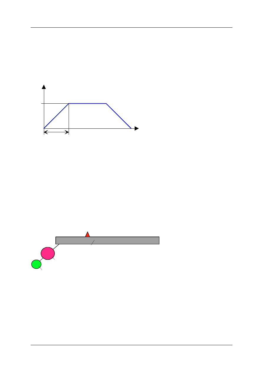
Positioning Module ZB4-256-SP1
01/98 AWB-EM 27-1296-GB
57
Ramp-up time [ms]
The ramp-up time of the rated speed depends heavily on the mechanics of the machine
(mechanical time constant of the complete drive line). It must always be greater than the
electrical time constant of the servo drive. The shorter the ramp-up time, the more the
machine is mechanically loaded.
Run up time to rated value
Rated value
Rated
n
n
H
t
Rated
n
H
t
t
Figure 25: Default of the ramp-up Time
Encoder resolution [incr./revs.]
The default of the encoder resolution depends on the type of position detection. There are
two types:
a) indirect position detection
Example:
The encoder has been flanged directly onto the motor shaft by a rotary axis. In this case,
the actual encoder resolution can be entered. In this type of position detection, slip and
play in the drive track are not detected and can not be compensated from by the position
control.
M
Actual-Position
Spindle (5mm/rev.)
Motor (3000 rpm)
E
Encoder (512 Incr./rev.)
Figure 26: Example of an Indirect Position Detection
b) direct position detection
The encoder is tapped direct on the output element e. g. in form of analogue linear-
potentiometers or in form of ultrasonic detector with an absolute-parallel encoder
interface. In this case, the encoder resolution must be recalculated to the motor rev. or the
rated speed of the motor must be converted into the output movement.

Positioning Module ZB4-256-SP1
01/98 AWB-EM 27-1296-GB
58
For the creation of the movement the actual encoder resolution and rated speed, are not
relevant, but rather is the result of both dimensions. Because only whole numbers (16 bits)
can be default values for the axis parameterizing, rounding errors can be caused during the
default of these dimensions with non whole numbers in transformation and reduction ratio in
the drive line. These rounding errors have an effect on the feed speed.
2,3152:1
M
Actual-Position
Spindle (5mm/Umdr)
Absolute-scale (0,01 mm/Incr)
Reduction
gears
Motor (3000 rpm.)
Figure 27: Calculation Example with a Direct Position Detection
The max. feed speed on the spindle is:
max
mm s
. min
s min.
mm
mm s
v
[
/ ] =
3000[ rev /
]
60[ /
]
1
2,3152
5[
/rev] = 107,9820317899[
/ ]
•
•
The encoder resolution is to convert to the motor shaft in this case:
Motor
R
=
5[
/ rev ]
0,01[
/
c ]
1
2,3152
= 215,9640635798[
c / rev ]
mm
mm In r.
In r.
•
In the axis parameters could be entered a motor rated encoder resolution of R
motor
=216 .
Further examples: linear motor (hydraulic cylinder) and linear measurement
Defaults:
total run route: 600mm
total time for 600mm route: 6s
=> encoder frequency: n*R=(600[mm]*1000[incr/mm] / 0.1 [min] = 600.000 [incr/min]
For the result from the encoder resolution and rated speed the following can be set e. g.:
N=60
-> R
Motor
=10.000
N=3.000
-> R
Motor
=200
Software terminal switch/Software-limits
The run area of the axis can be programmed with the aid of the software-limits. All Jobs are
automatically limited to these values internally. The corresponding bit is set in the response
telegram when the software-limits have been reached.
The software terminal switch should have a certain distance to the hardware terminal
switches.
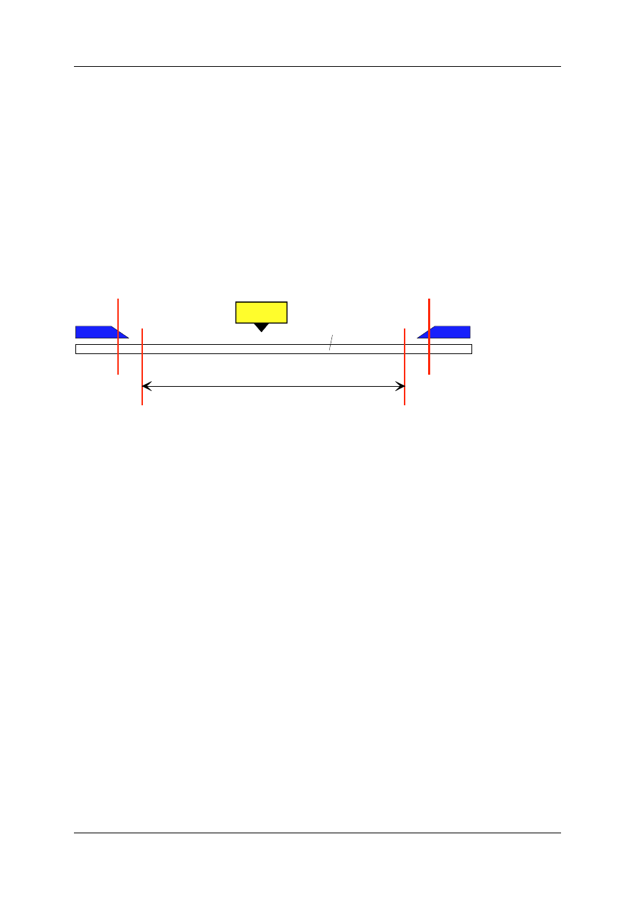
Positioning Module ZB4-256-SP1
01/98 AWB-EM 27-1296-GB
59
Example:
Position hardware terminal switch left:
1100
->
Software-limit minus = 3000
Position hardware terminal switch right:
42050 ->
Software-limit plus
= 40000
=> A run area of 37000 increments is available.
The zero point alteration is not yet defined with the initial start up of the axis. Because of this
the software-limits should be defined to the possible limits of the run area e. g. 100 / 60000.
After the zero point alteration has been defined, the software-limits can be adapted to the
position of the hardware terminal switch as described above.
AAAA
AAAA
AAAA
AAAA
AAAA
AAAA
AAAA
AAAA
AAAA
AAAA
AAAA
AAAA
AAAA
AAAA
AAAA
AAAA
AAAA
AAAA
AAAA
AAAA
AAAA
AAAA
AAAA
AAAA
AAAA
AAAA
AAAA
AAAA
AAAA
AAAA
AAAA
AAAA
AAAA
AAAA
AAAA
AAAA
AAAA
AAAA
AAAA
AAAA
AAAA
AAAA
AAAA
AAAA
AAAA
AAAA
AAAA
AAAA
AAAA
AAAA
AAAA
AAAA
AAAA
AAAA
AAAA
AAAA
AAAA
AAAA
AAAA
AAAA
AAAA
AAAA
AAAA
AAAA
AAAA
AAAA
AAAA
AAAA
AAAA
AAAA
AAAA
AAAA
AAAA
AAAA
AAAA
AAAA
AAAA
AAAA
AAAA
AAAA
AAAA
AAAA
AAAA
AAAA
AAAA
AAAA
AAAA
AAAA
AAAA
AAAA
AAAA
AAAA
AAAA
AAAA
AAAA
AAAA
AAAA
AAAA
AAAA
AAAA
AAAA
AAAA
AAAA
AAAA
AAAA
AAAA
AAAA
AAAA
AAAA
AAAA
AAAA
AAAA
AAAA
AAAA
AAAA
AAAA
AAAA
AAAA
AAAA
AAAA
AAAA
AAAA
AAAA
AAAA
AAAA
AAAA
AAAA
AAAA
AAAA
AAAA
AAAA
AAAA
AAAA
AAAA
AAAA
AAAA
AAAA
AAAA
AAAA
AAAA
AAAA
AAAA
AAAA
AAAA
AAAA
AAAA
AAAA
AAAA
AAAA
AAAA
AAAA
AAAA
AAAA
AAAA
AAAA
AAAA
AAAA
AAAA
AAAA
AAAA
AAAA
AAAA
AAAA
AAAA
AAAA
AAAA
AAAA
AAAA
AAAA
AAAA
AAAA
AAAA
AAAA
AAAA
AAAA
AAAA
AAAA
AAAA
AAAA
AAAA
AAAA
AAAA
AAAA
AAAA
AAAA
AAAA
AAAA
AAAA
AAAA
AAAA
AAAA
AAAA
AAAA
AAAA
AAAA
AAAA
AAAA
AAAA
AAAA
AAAA
AAAA
AAAA
AAAA
AAAA
AAAA
AAAA
AAAA
AAAA
AAAA
AAAA
AAAA
AAAA
AAAA
AAAA
AAAA
AAAA
AAAA
AAAA
AAAA
AAAA
AAAA
AAAA
AAAA
AAAA
AAAA
AAAA
AAAA
AAAA
AAAA
AAAA
AAAA
AAAA
AAAA
AAAA
AAAA
AAAA
AAAA
AAAA
AAAA
AAAA
AAAA
AAAA
AAAA
AAAA
AAAA
AAAA
AAAA
AAAA
AAAA
AAAA
AAAA
AAAA
AAAA
AAAA
AAAA
AAAA
AAAA
AAAA
AAAA
AAAA
AAAA
AAAA
AAAA
AAAA
AAAA
AAAA
AAAA
AAAA
AAAA
AAAA
AAAA
AAAA
AAAA
AAAA
AAAA
AAAA
AAAA
AAAA
AAAA
AAAA
AAAA
AAAA
AAAA
AAAA
AAAA
AAAA
AAAA
AAAA
AAAA
AAAA
AAAA
AAAA
AAAA
AAAA
AAAA
AAAA
AAAA
AAAA
AAAA
AAAA
AAAA
AAAA
AAAA
AAAA
AAAA
AAAA
AAAA
AAAA
AAAA
AAAA
AAAA
AAAA
AAAA
AAAA
AAAA
AAAA
AAAA
AAAA
AAAA
AAAA
AAAA
AAAA
AAAA
AAAA
AAAA
AAAA
AAAA
AAAA
AAAA
AAAA
AAAA
AAAA
AAAA
AAAA
AAAA
AAAA
AAAA
AAAA
AAAA
AAAA
AAAA
AAAA
AAAA
AAAA
AAAA
AAAA
AAAA
AAAA
AAAA
AAAA
AAAA
AAAA
AAAA
AAAA
AAAA
AAAA
AAAA
AAAA
AAAA
AAAA
AAAA
AAAA
AAAA
AAAA
AAAA
AAAA
AAAA
AAAA
AAAA
AAAA
AAAA
AAAA
AAAA
AAAA
AAAA
AAAA
AAAA
AAAA
AAAA
AAAA
AAAA
AAAA
AAAA
AAAA
AAAA
AAAA
AAAA
AAAA
AAAA
AAAA
AAAA
AAAA
AAAA
AAAA
AAAA
AAAA
AAAA
AAAA
AAAA
AAAA
AAAA
AAAA
AAAA
AAAA
AAAA
AAAA
AAAA
AAAA
AAAA
AAAA
AAAA
AAAA
AAAA
AAAA
AAAA
AAAA
AAAA
AAAA
AAAA
AAAA
AAAA
AAAA
AAAA
AAAA
AAAA
AAAA
AAAA
AAAA
AAAA
AAAA
AAAA
AAAA
AAAA
AAAA
AAAA
AAAA
AAAA
AAAA
AAAA
AAAA
AAAA
AAAA
AAAA
AAAA
AAAA
AAAA
AAAA
AAAA
AAAA
AAAA
AAAA
AAAA
AAAA
AAAA
AAAA
AAAA
AAAA
AAAA
AAAA
AAAA
AAAA
AAAA
AAAA
AAAA
AAAA
AAAA
AAAA
AAAA
AAAA
AAAA
AAAA
AAAA
AAAA
AAAA
AAAA
AAAA
AAAA
AAAA
AAAA
AAAA
AAAA
AAAA
AAAA
AAAA
AAAA
AAAA
AAAA
AAAA
AAAA
AAAA
AAAA
AAAA
AAAA
AAAA
AAAA
AAAA
AAAA
AAAA
AAAA
AAAA
AAAA
AAAA
AAAA
AAAA
AAAA
AAAA
AAAA
AAAA
AAAA
AAAA
AAAA
AAAA
AAAA
AAAA
AAAA
AAAA
AAAA
AAAA
AAAA
AAAA
AAAA
AAAA
AAAA
AAAA
AAAA
AAAA
AAAA
AAAA
AAAA
AAAA
AAAA
AAAA
AAAA
AAAA
AAAA
AAAA
AAAA
AAAA
AAAA
AAAA
AAAA
AAAA
AAAA
AAAA
AAAA
AAAA
AAAA
AAAA
AAAA
AAAA
AAAA
AAAA
AAAA
AAAA
AAAA
AAAA
AAAA
AAAA
AAAA
AAAA
AAAA
AAAA
AAAA
AAAA
AAAA
AAAA
AAAA
AAAA
AAAA
AAAA
AAAA
AAAA
AAAA
AAAA
AAAA
AAAA
AAAA
AAAA
AAAA
AAAA
AAAA
AAAA
AAAA
AAAA
AAAA
AAAA
AAAA
AAAA
AAAA
AAAA
AAAA
AAAA
AAAA
AAAA
AAAA
AAAA
AAAA
AAAA
AAAA
AAAA
AAAA
AAAA
AAAA
AAAA
AAAA
AAAA
AAAA
AAAA
AAAA
AAAA
AAAA
AAAA
AAAA
AAAA
AAAA
AAAA
AAAA
AAAA
AAAA
AAAA
AAAA
AAAA
AAAA
AAAA
AAAA
AAAA
AAAA
AAAA
AAAA
AAAA
AAAA
AAAA
AAAA
AAAA
AAAA
AAAA
AAAA
AAAA
AAAA
AAAA
AAAA
AAAA
AAAA
AAAA
AAAA
AAAA
AAAA
AAAA
AAAA
AAAA
AAAA
AAAA
AAAA
AAAA
AAAA
AAAA
AAAA
AAAA
AAAA
AAAA
AAAA
AAAA
AAAA
AAAA
AAAA
AAAA
AAAA
AAAA
AAAA
AAAA
AAAA
AAAA
AAAA
AAAA
AAAA
AAAA
AAAA
AAAA
AAAA
AAAA
AAAA
AAAA
AAAA
AAAA
AAAA
AAAA
AAAA
AAAA
AAAA
AAAA
AAAA
AAAA
AAAA
AAAA
AAAA
AAAA
AAAA
AAAA
AAAA
AAAA
AAAA
AAAA
AAAA
AAAA
AAAA
AAAA
AAAA
AAAA
AAAA
AAAA
AAAA
AAAA
AAAA
AAAA
AAAA
AAAA
AAAA
AAAA
AAAA
AAAA
AAAA
AAAA
AAAA
AAAA
AAAA
AAAA
AAAA
AAAA
AAAA
AAAA
AAAA
AAAA
AAAA
AAAA
AAAA
AAAA
AAAA
AAAA
AAAA
AAAA
AAAA
AAAA
AAAA
AAAA
AAAA
AAAA
AAAA
AAAA
AAAA
AAAA
AAAA
AAAA
AAAA
AAAA
AAAA
AAAA
AAAA
AAAA
AAAA
AAAA
AAAA
AAAA
AAAA
AAAA
AAAA
AAAA
AAAA
AAAA
AAAA
AAAA
AAAA
AAAA
AAAA
AAAA
AAAA
AAAA
AAAA
AAAA
AAAA
AAAA
AAAA
AAAA
AAAA
AAAA
AAAA
AAAA
AAAA
AAAA
AAAA
AAAA
AAAA
AAAA
AAAA
AAAA
AAAA
AAAA
AAAA
AAAA
AAAA
AAAA
AAAA
AAAA
AAAA
AAAA
AAAA
AAAA
AAAA
AAAA
AAAA
AAAA
AAAA
AAAA
AAAA
AAAA
AAAA
AAAA
AAAA
AAAA
AAAA
AAAA
AAAA
AAAA
AAAA
AAAA
AAAA
AAAA
AAAA
AAAA
AAAA
AAAA
AAAA
AAAA
AAAA
AAAA
AAAA
AAAA
AAAA
AAAA
AAAA
AAAA
AAAA
AAAA
AAAA
AAAA
AAAA
AAAA
AAAA
AAAA
AAAA
AAAA
AAAA
AAAA
AAAA
AAAA
AAAA
AAAA
AAAA
AAAA
AAAA
AAAA
AAAA
AAAA
AAAA
AAAA
AAAA
AAAA
AAAA
AAAA
AAAA
AAAA
AAAA
AAAA
AAAA
AAAA
AAAA
AAAA
AAAA
AAAA
AAAA
AAAA
AAAA
AAAA
AAAA
AAAA
AAAA
AAAA
AAAA
AAAA
AAAA
AAAA
AAAA
AAAA
AAAA
AAAA
AAAA
AAAA
AAAA
AAAA
AAAA
AAAA
AAAA
AAAA
AAAA
AAAA
AAAA
AAAA
AAAA
AAAA
AAAA
AAAA
AAAA
AAAA
AAAA
AAAA
AAAA
AAAA
AAAA
AAAA
AAAA
AAAA
AAAA
AAAA
AAAA
AAAA
AAAA
AAAA
AAAA
AAAA
AAAA
AAAA
AAAA
AAAA
AAAA
AAAA
AAAA
AAAA
AAAA
AAAA
AAAA
AAAA
AAAA
AAAA
AAAA
AAAA
AAAA
AAAA
AAAA
AAAA
AAAA
AAAA
AAAA
AAAA
AAAA
AAAA
AAAA
AAAA
AAAA
AAAA
AAAA
AAAA
AAAA
AAAA
AAAA
AAAA
AAAA
AAAA
AAAA
AAAA
AAAA
AAAA
AAAA
AAAA
AAAA
AAAA
AAAA
AAAA
AAAA
AAAA
AAAA
AAAA
AAAA
AAAA
AAAA
AAAA
AAAA
AAAA
AAAA
AAAA
AAAA
AAAA
AAAA
AAAA
AAAA
AAAA
AAAA
AAAA
AAAA
AAAA
AAAA
AAAA
AAAA
AAAA
AAAA
AAAA
AAAA
AAAA
AAAA
AAAA
AAAA
AAAA
AAAA
AAAA
AAAA
AAAA
AAAA
AAAA
AAAA
AAAA
AAAA
AAAA
AAAA
AAAA
AAAA
AAAA
AAAA
AAAA
AAAA
AAAA
AAAA
AAAA
AAAA
AAAA
AAAA
AAAA
AAAA
AAAA
AAAA
AAAA
AAAA
AAAA
AAAA
AAAA
AAAA
AAAA
AAAA
AAAA
AAAA
AAAA
AAAA
AAAA
AAAA
AAAA
AAAA
AAAA
AAAA
AAAA
AAAA
AAAA
AAAA
AAAA
AAAA
AAAA
AAAA
AAAA
AAAA
AAAA
AAAA
AAAA
AAAA
AAAA
AAAA
AAAA
AAAA
AAAA
AAAA
AAAA
AAAA
AAAA
AAAA
AAAA
AAAA
AAAA
AAAA
AAAA
AAAA
AAAA
AAAA
AAAA
AAAA
AAAA
AAAA
AAAA
AAAA
AAAA
AAAA
AAAA
AAAA
AAAA
AAAA
AAAA
AAAA
AAAA
AAAA
AAAA
AAAA
AAAA
AAAA
AAAA
AAAA
AAAA
AAAA
AAAA
AAAA
AAAA
AAAA
AAAA
AAAA
AAAA
AAAA
AAAA
AAAA
AAAA
AAAA
AAAA
AAAA
AAAA
AAAA
AAAA
AAAA
AAAA
AAAA
AAAA
AAAA
AAAA
AAAA
AAAA
AAAA
AAAA
AAAA
AAAA
AAAA
AAAA
AAAA
AAAA
AAAA
AAAA
AAAA
AAAA
AAAA
AAAA
AAAA
AAAA
AAAA
AAAA
AAAA
AAAA
AAAA
AAAA
AAAA
AAAA
AAAA
AAAA
AAAA
AAAA
AAAA
AAAA
AAAA
AAAA
AAAA
AAAA
AAAA
AAAA
AAAA
AAAA
AAAA
AAAA
AAAA
AAAA
AAAA
AAAA
AAAA
AAAA
AAAA
AAAA
AAAA
AAAA
AAAA
AAAA
AAAA
AAAA
AAAA
AAAA
AAAA
AAAA
AAAA
AAAA
AAAA
AAAA
AAAA
AAAA
AAAA
AAAA
AAAA
AAAA
AAAA
AAAA
AAAA
AAAA
AAAA
AAAA
AAAA
AAAA
AAAA
AAAA
AAAA
AAAA
AAAA
AAAA
AAAA
AAAA
AAAA
AAAA
AAAA
AAAA
AAAA
AAAA
AAAA
AAAA
AAAA
AAAA
AAAA
AAAA
AAAA
AAAA
AAAA
AAAA
AAAA
AAAA
AAAA
AAAA
AAAA
AAAA
AAAA
AAAA
AAAA
AAAA
AAAA
AAAA
AAAA
AAAA
AAAA
AAAA
AAAA
AAAA
AAAA
AAAA
AAAA
AAAA
AAAA
AAAA
AAAA
AAAA
AAAA
AAAA
AAAA
AAAA
AAAA
AAAA
AAAA
AAAA
AAAA
AAAA
AAAA
AAAA
AAAA
AAAA
AAAA
AAAA
AAAA
AAAA
AAAA
AAAA
AAAA
AAAA
AAAA
AAAA
AAAA
AAAA
AAAA
AAAA
AAAA
AAAA
AAAA
AAAA
AAAA
AAAA
AAAA
AAAA
AAAA
AAAA
AAAA
AAAA
AAAA
AAAA
AAAA
AAAA
AAAA
AAAA
AAAA
AAAA
AAAA
AAAA
AAAA
AAAA
AAAA
AAAA
AAAA
AAAA
AAAA
AAAA
AAAA
AAAA
AAAA
AAAA
AAAA
AAAA
AAAA
AAAA
AAAA
AAAA
AAAA
AAAA
AAAA
AAAA
AAAA
AAAA
AAAA
AAAA
AAAA
AAAA
AAAA
AAAA
AAAA
AAAA
AAAA
AAAA
AAAA
AAAA
AAAA
AAAA
AAAA
AAAA
AAAA
AAAA
AAAA
AAAA
AAAA
AAAA
AAAA
AAAA
AAAA
AAAA
AAAA
AAAA
AAAA
AAAA
AAAA
AAAA
AAAA
AAAA
AAAA
AAAA
AAAA
AAAA
AAAA
AAAA
AAAA
AAAA
AAAA
AAAA
AAAA
AAAA
AAAA
AAAA
AAAA
AAAA
AAAA
AAAA
AAAA
AAAA
AAAA
AAAA
AAAA
AAAA
AAAA
AAAA
AAAA
AAAA
AAAA
AAAA
AAAA
AAAA
AAAA
AAAA
AAAA
AAAA
AAAA
AAAA
AAAA
AAAA
AAAA
AAAA
AAAA
AAAA
AAAA
AAAA
AAAA
AAAA
AAAA
AAAA
AAAA
AAAA
AAAA
AAAA
AAAA
AAAA
AAAA
AAAA
AAAA
AAAA
AAAA
AAAA
AAAA
AAAA
AAAA
AAAA
AAAA
AAAA
AAAA
AAAA
AAAA
AAAA
AAAA
AAAA
AAAA
AAAA
AAAA
AAAA
AAAA
AAAA
AAAA
AAAA
AAAA
AAAA
AAAA
AAAA
AAAA
AAAA
AAAA
AAAA
AAAA
AAAA
AAAA
AAAA
AAAA
AAAA
AAAA
AAAA
AAAA
AAAA
AAAA
AAAA
AAAA
AAAA
AAAA
AAAA
AAAA
AAAA
AAAA
AAAA
AAAA
AAAA
AAAA
AAAA
AAAA
AAAA
AAAA
AAAA
AAAA
AAAA
AAAA
AAAA
AAAA
AAAA
AAAA
AAAA
AAAA
AAAA
AAAA
AAAA
AAAA
AAAA
AAAA
AAAA
AAAA
AAAA
AAAA
AAAA
AAAA
AAAA
AAAA
AAAA
AAAA
AAAA
AAAA
AAAA
AAAA
AAAA
AAAA
AAAA
AAAA
AAAA
AAAA
AAAA
AAAA
AAAA
AAAA
AAAA
AAAA
AAAA
AAAA
AAAA
AAAA
AAAA
AAAA
AAAA
AAAA
AAAA
AAAA
AAAA
AAAA
AAAA
AAAA
AAAA
AAAA
AAAA
AAAA
AAAA
AAAA
AAAA
AAAA
AAAA
AAAA
AAAA
AAAA
AAAA
AAAA
AAAA
AAAA
AAAA
AAAA
AAAA
AAAA
AAAA
AAAA
AAAA
AAAA
AAAA
AAAA
AAAA
AAAA
AAAA
AAAA
AAAA
AAAA
AAAA
AAAA
AAAA
AAAA
AAAA
AAAA
AAAA
AAAA
AAAA
AAAA
AAAA
AAAA
AAAA
AAAA
AAAA
AAAA
AAAA
AAAA
AAAA
AAAA
AAAA
AAAA
AAAA
AAAA
AAAA
AAAA
AAAA
AAAA
AAAA
AAAA
AAAA
AAAA
AAAA
AAAA
AAAA
AAAA
AAAA
AAAA
AAAA
AAAA
AAAA
AAAA
AAAA
AAAA
AAAA
AAAA
AAAA
AAAA
AAAA
AAAA
AAAA
AAAA
AAAA
AAAA
AAAA
AAAA
AAAA
AAAA
AAAA
AAAA
AAAA
AAAA
AAAA
AAAA
AAAA
AAAA
AAAA
AAAA
AAAA
AAAA
AAAA
AAAA
AAAA
AAAA
AAAA
AAAA
AAAA
AAAA
AAAA
AAAA
AAAA
AAAA
AAAA
AAAA
AAAA
AAAA
AAAA
AAAA
AAAA
AAAA
AAAA
AAAA
AAAA
AAAA
AAAA
AAAA
AAAA
AAAA
AAAA
AAAA
AAAA
AAAA
AAAA
AAAA
AAAA
AAAA
AAAA
AAAA
AAAA
AAAA
AAAA
AAAA
AAAA
AAAA
AAAA
AAAA
AAAA
AAAA
AAAA
AAAA
AAAA
AAAA
AAAA
AAAA
AAAA
AAAA
AAAA
AAAA
AAAA
AAAA
AAAA
AAAA
AAAA
AAAA
AAAA
AAAA
AAAA
AAAA
AAAA
AAAA
AAAA
AAAA
AAAA
AAAA
AAAA
AAAA
AAAA
AAAA
AAAA
AAAA
AAAA
AAAA
AAAA
AAAA
AAAA
AAAA
AAAA
AAAA
AAAA
AAAA
AAAA
AAAA
AAAA
AAAA
AAAA
AAAA
AAAA
AAAA
AAAA
AAAA
AAAA
AAAA
AAAA
AAAA
AAAA
AAAA
AAAA
AAAA
AAAA
AAAA
AAAA
AAAA
AAAA
AAAA
AAAA
AAAA
AAAA
AAAA
AAAA
AAAA
AAAA
AAAA
AAAA
AAAA
AAAA
AAAA
AAAA
AAAA
AAAA
AAAA
AAAA
AAAA
AAAA
AAAA
AAAA
AAAA
AAAA
AAAA
AAAA
AAAA
AAAA
AAAA
AAAA
AAAA
AAAA
AAAA
AAAA
AAAA
AAAA
AAAA
AAAA
AAAA
AAAA
AAAA
AAAA
AAAA
AAAA
AAAA
AAAA
AAAA
AAAA
AAAA
AAAA
AAAA
AAAA
AAAA
AAAA
AAAA
AAAA
AAAA
AAAA
AAAA
AAAA
AAAA
AAAA
AAAA
AAAA
AAAA
AAAA
AAAA
AAAA
AAAA
AAAA
AAAA
AAAA
AAAA
AAAA
AAAA
AAAA
AAAA
AAAA
AAAA
AAAA
AAAA
AAAA
AAAA
AAAA
AAAA
AAAA
AAAA
AAAA
AAAA
AAAA
AAAA
AAAA
AAAA
AAAA
AAAA
AAAA
AAAA
AAAA
AAAA
AAAA
AAAA
AAAA
AAAA
AAAA
AAAA
AAAA
AAAA
AAAA
AAAA
AAAA
AAAA
AAAA
AAAA
AAAA
AAAA
AAAA
AAAA
AAAA
AAAA
AAAA
AAAA
AAAA
AAAA
AAAA
AAAA
AAAA
AAAA
AAAA
AAAA
AAAA
AAAA
AAAA
AAAA
AAAA
AAAA
AAAA
AAAA
AAAA
AAAA
AAAA
AAAA
AAAA
AAAA
AAAA
AAAA
AAAA
AA
A
AAA
AAA
AAA
AAA
AAA
AAA
AAA
AAA
AAA
AAA
AAA
AAA
AAA
Terminal switch -
1100
Terminal switch +
42050
Software-Limit -
3000
Software-Limit +
40000
Machine saddle
scale
Run area = 37000 Increments
Figure 28: Example Defaulting the Software-Limits
Maximum lag error
A real axis (motor and mechanics) shows a definite dynamic due to its definite acceleration
volume. This feature results in a so called lag error with a movement of the axis minus the
lag error is the distance to which the actual position trails behind the set position. The lag
error is directly proportional to the relation between the position control gain amplification KV
and the set speed. The lag error is permanently monitored in the position control of the
positioning module. If too large a lag error occurs during an axis movement, this indicates an
electrical or mechanical error. For instance the axis could collide with an obstruction during
operations or there is a mechanical defect in the drive system (clamping etc.). The drive
concerned must be immediately switched off in order to minimise damage.
If the failure of an axis occurs due to the axis exceeding the maximum preset value, the
regulator enable signal will be removed and the analogue output value will be set to zero
volts. The axis can only be operated through a new controller release. The lag error is
registered in the corresponding bit with the response telegram of the positioning module.
The maximum lag error for an axis can be defaulted as follows. First a very high max. lag
error is parameterized (e. g. 20000). The axis concerned is then run with max. speed. In this
case, the continual jog-function can be used. The parameter of the demand data channel is
set so that, for instance, the actual lag error in block 2 is transmitted to the master PLC (see
Chap. 4.5.3). The actual lag error can now be monitored. The actual lag error serves as a
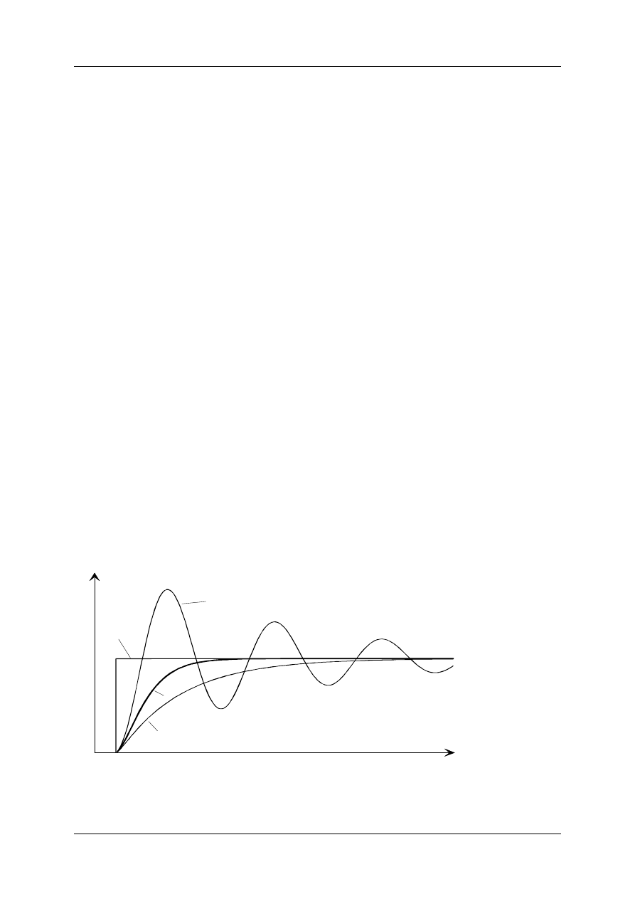
Positioning Module ZB4-256-SP1
01/98 AWB-EM 27-1296-GB
60
measure for the default of max. lag error; this should be set a little higher in order to avoid
the immediate response of the lag error monitoring, if the load of the axis changes.
Typical value for an electrical servo axis: 3000 increments in a ramp-up time of 200ms.
In-Position window
The In-Position window defaults the tolerance with which the target position is approached.
As soon as the axis is within this window, the In-Position-bit is set in the response telegram.
By processing internal Jobs a looping of the Jobs can be achieved through the default of a
large position window. If the In-Position window is too small, the axis will not reach its
destination.
The In-Position window is also dependant on the resolution encoder and mechanical friction
of the axis.
Typical value: 20 increments
For the initial start up the In-Position window should be set to 100...200 increments and
accordingly reduced after the position control amplification (KV-Factor) has been optimally
set.
KV-Factor
The KV-Factor defaults the position control amplification. According to the rule when the
precontrol is not active (see below):
set voltage = lag error KV
The lag error is then the difference between the set position value minus the actual position.
The KV-Factor should be set so that the axis - according to its dynamic - can reach its target
position swiftly without overshooting. If the KV-Factor is too high, the axis overshoots its
position, and if set too low the positioning takes a long time. The following Figure illustrates
the step response dependant on the KV-Factor.
KV-Factor too high
KV-Factor too low
KV-Factor correct
t
U
Step
Figure 29: Step Responses dependant on the KV-Factor
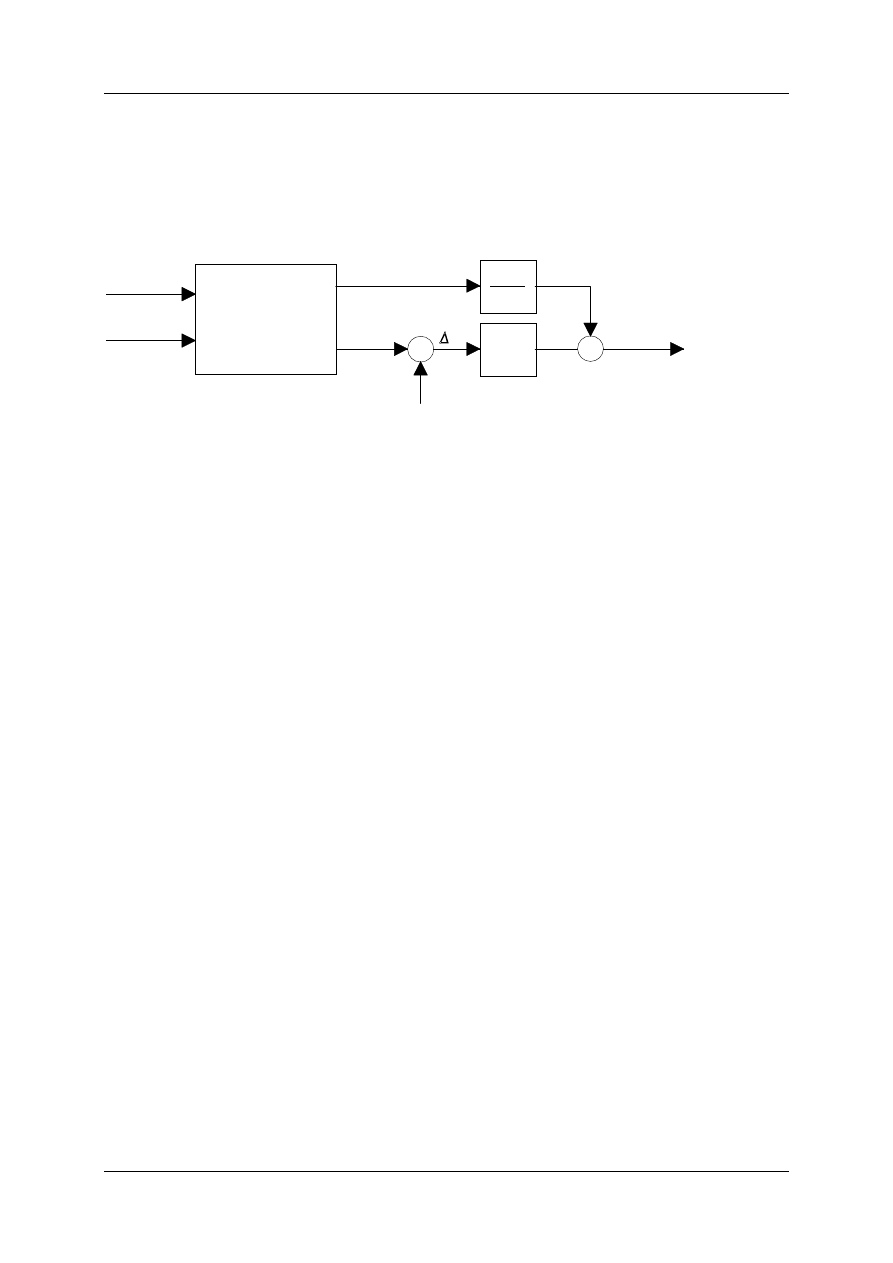
Positioning Module ZB4-256-SP1
01/98 AWB-EM 27-1296-GB
61
KG-Factor
With the aid of the KG-Factor the speed preset can be parameterized. The speed preset
reduces the lag error to zero in phases of movement in which there is a constant speed. The
position control is extended for this reason.
Target pos.
Speed
Generating
command
variables
s
s
n
set
set
-
KV
+
KG
v
set
s
actual
255
Figure 30: Position Control with Preset
For the initial start up the KG-Factor should be set to zero in order to deactivate the
precontrol. As previously described, the next step is to optimise the KV-Factor. The KG-
Factor can then be set greater than zero. Low values should be used to begin with. The set
speed of the axis is fully modulated with KG=255.
By the initial start up the KG-Factor should be set to zero. First, after the KV-Factor has been
optimally set, the dynamic of the axis can then be raised further with the aid of KG.
TIP:
The dynamic loading of the mechanic increases with an increasing KG-Factor!
KS-Factor
With the KS-Factor an extension of the position control can be activated in order to enable
exact positioning of the servo hydraulic drives. In order to achieve this, some requirements of
the hydraulic drive system engineering have to be met:
a) high operating pressure with sufficient dimensioned accumulator
b) the servo valves should be equipped with a return path if possible
c) when using servo valve/control-valve connectors with large volumetric flows, the control-
valve should be equipped with a return path.
Servo hydraulic axes, as opposed to electrical servo drives, have under some circumstances
quite a high friction grip when the cylinder is at a stand still. This effect is caused by the high
sealing volume in order to seal the cylinder. As soon as the cylinder moves the friction grip
moves almost immediately over to the so called gliding friction. This is significantly less in
relation to friction grip. This means for the whole unit, servo valve and cylinder, at first a
certain amount of voltage must be put on the servo valve until enough pressure is built up
inside the powder camera, and the cylinder starts to move. As soon as the cylinder moves
the voltage can be removed.

Positioning Module ZB4-256-SP1
01/98 AWB-EM 27-1296-GB
62
With the aid of the KS-Factor the voltage can be set enough to overcome the grip friction. KS
is referred to the value of 255, which is equivalent to a current of 5 Volts on an analogue
output. With the following equation the voltages can be converted into KS: KS = X[V] * 51.
Whereby the X should be set in Volts.
A servo hydraulic axis can be started up as follows:
1. Approximate definition of the breakaway voltage with the battery box or the Job-ID 16
(controlling the axis i).
2. KS-Factor calculation with the above equation
3. Sending a Job (e. g. Job-ID 13/14 : Jog with a 200 increments route)
4. Fine adjustment of the KS-Factor. The KS-Factor should not be larger than necessary in
order to avoid overshooting the positioning of the target point.
FS-Factor
With the aid of this factor the sensitivity of the Stick-Slip-Compensation can be set.
The default value must be set with 2. KS-Factor might have to be raised, depending on the
encoder resolution. A sign for this is when the hydraulic axis starts too late reaching the
target position with the Stick-Slip-activities.
KVSK-Factor
With hydraulic cylinders it can be necessary to compensate the uneven surface conditions
which result of the piston rod. With the aid of the KVSK-Factor it is possible to raise and/or
lower KV- and KS-Factors depending on direction. The default value is zero or 80
Hex
amounts to a symmetrical KV-Factor. For the KVSK = FF
Hex
the KV in positive direction of
movement is twice a large as the KV in negative direction. For KVSK = 7F
Hex
the KV in
negative direction of movement is twice as large as the KV in positive direction.
5.1.3 Procedure for Starting up an Axis
a)
Initialising an axis
Because the parameter for starting up an axis must often be reset, it is recommended to
read in a push-button onto the PLC for the start up, in order to start the initialising an axis:
L I0.0
=´X1MINIT1
The push-button initialises axis 1 of positioning module 1 after the parameter has been
adapted via on-line change.
b)
Testing if the encoder connection is OK
To test if the axis mode has been correctly defaulted, the axis can be moved mechanically
with an unreleased controller, during which the actual position value must change in the LED
of the PLC.

Positioning Module ZB4-256-SP1
01/98 AWB-EM 27-1296-GB
63
c)
Direction of Rotation of the Drive
Now it must be checked if the rotating direction of the drive corresponds with the polarity of
the analogue output. The controller must be released to the drive, however not over the
positioning module, because the position control for this should not be closed (setting 24 V
on the drive amplifier's controller release input). When a low positive voltage is set on the
analogue input of the drive amplifier, the drive should move. The actual value of the axis in
the LED on the PLC must change, specifically in the positive direction! Otherwise the polarity
of the analogue output on the PS4-401 must be reversed. A bit can be set in the word ramp-
up time for this (see also Chap. 4.5.2):
Either
-
changing the counting direction:
L KW 300
0 KHW 2000
= ´W1TH1
or
-
changing the analogue output polarity
L KW 300
0 KHW 1000
= ´W1TH1
d)
Releasing the controller
The controller can now be released via the positioning module. The axis which should be
taken into position control should be specified by the byte B#AX. It should be possible to
operate the drive steadily in position control (drift compensation).
In order to ensure that the controller can be released again at any time during the start up, it
is also useful to give this command to a push-button:
L I0.1
=´X1INIT
e)
Adjusting the position control
To adjust the position control the axis must be somehow moveable. Manual operation is
suitable for this purpose. This can also be accomplished temporary with a push-button.
e. g.
Continual jogging of axis 1 of the positioning module 1 in positive and negative
direction.
L I0.2
= ´X1M1JOGM
L I0.3
= ´X1M1JOGP
To aid adjustment of the position control an oscilloscope should be connected to the
analogue output of the axis concerned.
Ideally linear speed ramps should be visible when the axis is being run. If the ramps are
heavily looped the KV-Factor must be raised. If the axis overshoots heavily the KV-Factor
must be reduced. When the axis can be more or less well run (safe in position feedback), the

Positioning Module ZB4-256-SP1
01/98 AWB-EM 27-1296-GB
64
zero point alteration and the software-limits should be set. The closed-loop control can only
be optimised after this.
f
)
Setting the Zero Point Shift
The actual value that is used for the position control in positioning mode and is returned to
the master PLC, should not zero-cross anywhere in the whole run area. Otherwise the
positioning module would, with a lag error, immediately abort the procedure. With the
incremental encoders the zero point is set during the reference Job. With absolute encoders
an encoder zero crossing can occur when an encoder has a resolution of more than 16 bits.
In this case one is forced to restrict the upper and lower bits, depending on the required
resolution. In this case, one must carry out the following test.
Test with a battery box
•
Pull the clamp block for the digital input and output (disconnect the controller release)
•
Cause a controller release on the servo amplifiers with the use of 24 V
•
Separate the analogue set value outputs on the PS4-401-MM2
•
Connect the battery box to the analogue set value inputs of the servo amplifier
•
Bring the controls to run
Alternative: Test in control mode (Job-ID 16)
•
Instead of a battery box the drives can be controlled directly by the master-PLC.
The position control value can be monitored in the master PLC. The axes are then moved, if
possible manually, or run with the aid of the battery box over the whole run area. If a
controller zero crossing occurs, a zero point offset should be entered in the controller release
telegram in order to move the run area into the positive area.
Example of correcting through zero point shift
The absolute encoder (binary coded) shows a zero crossing in the first third of the run area
of the axis. A zero point shift has to be defined, so that the actual value 15000 on the
encoder zero position is defined.
555435
0
35000
SWL+
50000
15000
SWL-
5000
Actual-Position
=
Actual encoder -
Offset
Actual encoder
Figure 31: Correcting the Zero Crossing through the Zero Point Offset

Positioning Module ZB4-256-SP1
01/98 AWB-EM 27-1296-GB
65
The actual position is calculated internally by subtracting the zero offset from the actual read
in encoder value. This offset is calculated as follows:
If the encoder delivers the position zero, the actual position should show the value 15000
Offset = actual encoder - actual position = 0 - 15000 = -15000
Negative values are subtracted in the positioning module from FFFF
hex
=65535
10
:
-15000 ==65535 - 15000 = 50535
This value must be entered in the telegram Job-ID 2 as the zero point offset.
Test:
Actual encoder = 35000
-> Actual position = 35000 - 50535 = -15535 = 65535 - 151535 = 50000
Software-limits (see Chap. 5.1.2.2)
h)
Optimising the position control
After setting the zero point shift and the software-limits, the axis can be run safely. As a
further optimisation the axis should operated with 10 V - rated speed - under load. With the
aid of automatic sequencer, the axis is driven back and forth between two positions.
When using servo hydraulic axes, the KS-Factor should also be set. The size of KS can be
defined by measuring an analogue voltage directly onto the axis, as previously described. It
can however, starting with a low value for KS be raised step by step, until the axis beings to
move. Here a Job is transmitted from the master PLC to the positioning module. To start
with, the hydraulic cylinder with a small KS will not move. The cylinder begins to move at a
certain limit value. The KS-Factor should be set only slightly higher than the limit value so
that the cylinder does not tend to overshoot during the target positioning.
All significant steps for an axis are now complete and the next axis can follow.

Positioning Module ZB4-256-SP1
01/98 AWB-EM 27-1296-GB
66
5.1.4 Example for Parameterization of an Axis
Data:
•
Three axes with absolute digital binary coded encoders (indirect position detection).
•
Axis 1 and 3 are mechanically coupled and should be operated synchronous to one
another.
•
The dynamic of axis 2 should be set slightly higher than axes 1 and 3.
The axis parameters have been entered in the following table. You will find the formula in
Appendix A for your own use.
Axis Parameter
Plant:
Date: . .
Place:
Operator:
Axis parameter
Axis 1
Axis 2
Axis 3
Axis Mode
00011100
bin
==
1C
hex
01011100
bin
==
5C
hex
10011100
bin
==
9C
hex
encoder resolution [Incr]
16Bit
512
512
512
rated value [rev/min]
16Bit
3000
3000
3000
time constant [ms]
11Bit
300
200
300
factor time constant []
1Bit
(0=1x, 1=10x)
0
0
0
Pol. analogue-output[]
1Bit
(0=+1x, 1=-1x)
0
0
0
counting direction actual pos. []
1Bit
(0=+1x, 1=-1x)
0
0
0
evaluation LE4-622-CX1 []
2Bit
(00=4x,10=2x, 01=1x,
11=½x)
0
0
0
software-limit minus [Incr]
16Bit
2000
4000
3000
software-limit plus [Incr]
16Bit
40000
32000
40000
max. lag error [Incr]
16Bit
2000
3000
2000
In-Position window [Incr]
8/16Bit
10
10
10
KV-Factor []
8Bit
24
18
53
KG-Factor []
8Bit
0
120
0
KS-Factor []
8Bit
12
0
0
FS-Factor []
8Bit
2
0
0
KVSK-Factor []
8Bit
A3
hex
0
0

Positioning Module ZB4-256-SP1
01/98 AWB-EM 27-1296-GB
67
6 Trouble Shooting
6.1 Communication
Fault
Cause
Solution
Run-LED blinks
Bus address incorrect
master PLC/device configuration:
- Position of the PosMod on the line
DIP-Switch on the PS4-401-MM2 does not
correspond with the master-configuration
Run-LED blinks
Communications
parameter incorrect
master PLC/device configuration:
- 17 Byte receive
- 20 Bytes send
Run-LED blinks
pin assignment Suconet K
faulty
pin assignment according to AWA
Run-LED blinks
Bus terminating resistors
open/close bus terminating resistors according to
AWA
6.2 Controller release / Ready
Fault
Cause
Solution
controller is not
released
Axis was not initialised
Status word 1, Bit #7 =1?
⇒
Axis parameter faulty, examine
or
21
hex
is not present in communications-FIFO
⇒
examine sequence in i#posmod.q42
Digital inputs onto
the PS4-401 do not
come
Drive does not indicate
controller ready
Check the state of drive controller, remove fault on
the drive and quit
Digital inputs onto the
PS4-401 do not come
Controller was not
released (ID2)
master PLC: ID2, Bit#5..#7 = 1 ?

Positioning Module ZB4-256-SP1
01/98 AWB-EM 27-1296-GB
68
6.3 Drives
Fault
Cause
Solution
After controller
release, the drive
runs up uncontrollably
Poling the set values and
direction of rotation
encoders do not
correspond
Set ID 1, Bit #12 of word 6 in order to rotate the
polarity of the analogue output.
The axis does not run
with 10V with the
programmed max.
speed
Encoder resolution/rated
value
Were the gearings eventually not or incorrectly
taken into consideration? See Chap. 5.1.2.1 and
The axis immediately
retires with the run
order (controller -
ready
signal
disappears)
lag error monitoring
appears
(Byte 2, #0..2)
enlarge max. lag error
examine encoder resolution and rated value
monitoring the wire break
with incr. encoders position
(Byte 2, #4) appears
examine encoder wiring,
examine the 5V-encoder supply
incorrect poling of the set
value

Positioning Module ZB4-256-SP1
01/98 AWB-EM 27-1296-GB
69
7 Appendix A
Axis Parameter
Plant:
Date: . .
Place:
Operator:
Axis parameter
Axis 1
Axis 2
Axis 3
encoder resolution [Incr]
16Bit
rated value [rpm]
16Bit
time constant [ms]
11Bit
Factor time constant []
1Bit
(0=1x, 1=10x)
Pol. analogue-output []
1Bit
(0=+1x, 1=-1x)
counting direction actual pos. []
1Bit
(0=+1x, 1=-
1x)
Evaluation LE4-622-CX1 []
2Bit
(00=4x,10=2x,
01=1x, 11=½x)
software-limit minus [Incr]
16Bit
software-limit plus [Incr]
16Bit
max. lag error [Incr]
16Bit
In-Position window [Incr]
8/16Bit
KV-Factor []
8Bit
KG-Factor []
8Bit
KS-Factor []
8Bit
FS-Factor []
8Bit
KVSK-Factor []
8Bit

Positioning Module ZB4-256-SP1
01/98 AWB-EM 27-1296-GB
70
8 Appendix B
Setting up
Check list
Plant: Date: . .
Place:
Operator:
1 Hardware
1.1 Are the electr. terminal switches wired and open?
1.2 Are the outputs of the controller release on the PS4-401 correctly wired
to the drives?
1.3 Are the controller ready indicators of the drives on the PS 401 inputs? (The signal is
not available with the hydraulic axes: modulate the master-output to controller ready)
1.4 Are the analogue set values executed as a shielded cable?
1.5 Set Suconet K address switch to PS4-401
2 Master-PLC - Software
2.1 Configure all axes as test axes (Axis Mode = DC
HEX
)
Module i#par.q42
2.2 Reset the controller release for all axes
Module i#posmod.q42, b#AX=0
2.3 Set Suconet K parameter for the positioning module (20 Bytes send, 17 Bytes receive)
2.4 With incremental encoders: skip commanding the reference
Module i#posmod.q42
3 Setting up the Axis
3.1 Pull off the analogue-terminal strip
3.2 Start master PLC and PS4-401 and examine the communication

Positioning Module ZB4-256-SP1
01/98 AWB-EM 27-1296-GB
71
Setting up
Check list
3.3 Check the addresses / parameter in the master device configuration
3.4 Check the address on the PS4-401
TIP:
After changing the DIP-Switch setting, a new cold-start of the PS4-401 must
be carried out!
3.5 Have the bus terminating resistors been set correctly?
3.6 Have the Suconet-K-cables eventually been swapped over?
3.7 Begin with the most uncritical axis:
3.8 Enter the axis parameter into module ipar.q42 (AxMode ¹DC
HEX
)
3.9 Release the axis
e. g. Axis 1: Module i#posmod.q42, L KB 1 = b#AX
3.10 When the axis „goes out of control“: Is the polarity analogue correct?
TIP: Can the ramp-up time be set by Bit #12 of the parameter?
3.11 Firstly set KV to a smaller value (e. g. KV=4)
3.12 Connect the oscilloscope to the analogue set value output concerned
3.13 Optimise KV (the ramp must look symmetrical)
3.14 Axis can be run stable manually (JOB-ID 13/14)
3.15 Set zero point (Module i#par.q42, initialise and release the axis once again)
3.16 Set Software-limits (Module i#par.q42, initialise and release the axis once
again)
3.17 Manual operation complete
3.18 Develop automatic-operation (e. g. with sequencer following Module
iouto.q42)

Positioning Module ZB4-256-SP1
01/98 AWB-EM 27-1296-GB
72
9 Appendix C
FS-Sensitivity
Stick-Slip-Compensation Sensitivity
KG
Servo gain factor
KS
Stick-Slip-Compensation factor
KV
Position control gain
KVSK
Factor for asymmetric position control gain
n
act
actual value of speed
n
set
setpoint value of speed
N
rated speed
R
encoder resolution
∆
s
lag error
s
act
actual position
s
set
setpoint value of position
t
h
ramp-up time
v
max
maximum speed

Positioning Module ZB4-256-SP1
01/98 AWB-EM 27-1296-GB
73
Index
A
absolute speed............................................................................................................................................................................. 47
Absolute-Analogue-Encoder ...................................................................................................................................................... 14
Absolute-Digital-Encoder .......................................................................................................................................................... 12
analogue outputs......................................................................................................................................................................... 11
Analogue power inputs............................................................................................................................................................... 40
Analogue voltage inputs ............................................................................................................................................................. 40
Analogue voltage outputs ........................................................................................................................................................... 40
asynchronous point-to-point positioning...................................................................................................................................... 8
automatic sequencer ............................................................................................................................................................. 18; 26
axis Parameter .............................................................................................................................................................................. 5
B
battery box .................................................................................................................................................................................. 64
binary-code ................................................................................................................................................................................. 35
Break Job .............................................................................................................................................................................. 31; 46
C
command variable .................................................................................................................................................................... 6; 7
commanding telegram ................................................................................................................................................................ 20
commando interface ................................................................................................................................................................... 24
communication driver................................................................................................................................................................. 18
compensation of the Stick-Slip-effect ........................................................................................................................................ 37
confirmation ......................................................................................................................................................................... 31; 32
control mode............................................................................................................................................................................... 48
controller is not released............................................................................................................................................................. 67
controller ready...................................................................................................................................................30; 39; 55; 68; 70
controller release ...............................................................................................11; 24; 30; 31; 39; 42; 48; 53; 55; 59; 63; 64; 70
controller release (asynchronous)............................................................................................................................................... 52
controller release (synchronous) ................................................................................................................................................ 39
Controlling the Axes .................................................................................................................................................................. 48
counting direction........................................................................................................................................................... 37; 63; 66
D
definition of coding .................................................................................................................................................................... 35
demand data channel ............................................................................................................................................................ 40; 52
detection of wire breakage.......................................................................................................................................................... 14
device configuration ................................................................................................................................................................... 56
digital inputs ............................................................................................................................................................................... 11
digital outputs ............................................................................................................................................................................. 11
DIP-switch.................................................................................................................................................................................. 17
direction of Rotation................................................................................................................................................................... 63
E
emergency-stop-circuit ............................................................................................................................................................... 55
encoder counting direction ......................................................................................................................................................... 36
encoder resolution .................................................................................................................................................................. 5; 30
encoder Systems ......................................................................................................................................................................... 12
encoder types .............................................................................................................................................................................. 34
evaluation LE4-622-CX1 ........................................................................................................................................................... 32

Positioning Module ZB4-256-SP1
01/98 AWB-EM 27-1296-GB
74
F
Feed-Override...........................................................................................................................................8; 31; 41; 44; 45; 47; 50
Flash-RAM-Memory module ..................................................................................................................................................... 10
flow Diagram.............................................................................................................................................................................. 22
friction grip compensation............................................................................................................................................................ 5
FS-Factor ........................................................................................................................................................................ 32; 62; 66
G
Generating a Job ......................................................................................................................................................................... 25
gray-code .................................................................................................................................................................................... 35
H
Hardware Engineering................................................................................................................................................................ 10
I
impulse multiplication .................................................................................................................................................... 36; 37; 42
Incremental Encoder................................................................................................................................................................... 14
Incremental-Encoder .................................................................................................................................................................. 15
individual commanding .............................................................................................................................................................. 25
Initialising Axis Parameter ......................................................................................................................................................... 32
In-Pos-Flag ................................................................................................................................................................................. 29
In-Position window ..............................................................................................................................................5; 30; 32; 49; 60
Integrating the Positioning Modules .......................................................................................................................................... 23
internal Jobs..................................................................................................................................................29; 45; 46; 49; 50; 51
internal Jobs periodically............................................................................................................................................................ 51
internal Jobs sequential .............................................................................................................................................................. 50
invalid initialising data ............................................................................................................................................................... 30
J
Job .............................................................................................................................................................................................. 44
Job 00 ......................................................................................................................................................................................... 32
Job 01 ......................................................................................................................................................................................... 32
Job 02 ......................................................................................................................................................................................... 39
Job 03 ......................................................................................................................................................................................... 40
Job 04/05 .................................................................................................................................................................................... 44
Job 06 ......................................................................................................................................................................................... 46
Job 07 ......................................................................................................................................................................................... 46
Job 08 ......................................................................................................................................................................................... 46
Job 09 ......................................................................................................................................................................................... 47
Job 10 ......................................................................................................................................................................................... 47
Job 13/14 .................................................................................................................................................................................... 47
Job 16 ......................................................................................................................................................................................... 48
Job 17 ......................................................................................................................................................................................... 49
Job 20 ......................................................................................................................................................................................... 49
Job 21 ......................................................................................................................................................................................... 50
Job 25 ......................................................................................................................................................................................... 50
Job 26 ......................................................................................................................................................................................... 51
Job 28 ......................................................................................................................................................................................... 51
Job 30 ......................................................................................................................................................................................... 52
Job 31 ......................................................................................................................................................................................... 52
Job zero....................................................................................................................................................................................... 31
Job-ready-Flag............................................................................................................................................................................ 29
Jobs table .................................................................................................................................................................................... 18
Jog .............................................................................................................................................................................................. 31
Jog Plus / Jog Minus................................................................................................................................................................... 47

Positioning Module ZB4-256-SP1
01/98 AWB-EM 27-1296-GB
75
K
KG-Factor....................................................................................................................................................................... 32; 61; 66
KS-Factor .....................................................................................................................................................32; 37; 61; 62; 65; 66
KV-Factor.................................................................................................................................................5; 30; 32; 37; 60; 61; 66
KVSK-Factor............................................................................................................................................................32; 38; 62; 66
L
lag distance ................................................................................................................................................................................. 37
lag error .................................................................................... 6; 7; 8; 18; 24; 29; 31; 35; 37; 40; 48; 52; 54; 60; 61; 64; 66; 68
LE4-622-CX1 ...............................................................................................................................................13; 14; 15; 34; 37; 42
linear motor ................................................................................................................................................................................ 58
Line-End-Mask........................................................................................................................................................................... 44
Line-Start-Mask.......................................................................................................................................................................... 44
M
machine zero point ..................................................................................................................................................................... 42
main program.............................................................................................................................................................................. 18
manual operating ........................................................................................................................................................................ 47
maximum error ........................................................................................................................................................................... 32
maximum lag error ............................................................................................................................................................... 30; 59
MMI-bit ...................................................................................................................................................................................... 24
module structure ......................................................................................................................................................................... 19
O
optimising the position control................................................................................................................................................... 65
order number .............................................................................................................................................................................. 28
order telegram............................................................................................................................................................................. 31
P
piston surfaces ............................................................................................................................................................................ 38
position control........................................................................................................................................................................... 48
Position Control Loop .................................................................................................................................................................. 6
precontrol factor ........................................................................................................................................................................... 5
program module.......................................................................................................................................................................... 19
Protocol ...................................................................................................................................................................................... 28
protocol layer.............................................................................................................................................................................. 18
Q
quadrature decoding ................................................................................................................................................................... 14
quitting.................................................................................................................................................................................. 21; 29
R
ramp-up time ................................................................................................................................... 5; 7; 8; 30; 36; 38; 57; 63; 71
rated speed ........................................................................................................................... 5; 7; 8; 30; 36; 38; 47; 56; 57; 58; 65
reference cam........................................................................................................................................................................ 13; 41
reference point ..........................................................................................................................................................15; 29; 42; 43
reference point switch ........................................................................................................................................16; 17; 41; 42; 43
referencing....................................................................................................................................................14; 15; 29; 40; 42; 43
referencing process..................................................................................................................................................................... 42
reinforcement.............................................................................................................................................................................. 37

Positioning Module ZB4-256-SP1
01/98 AWB-EM 27-1296-GB
76
reinforcement of the position control loop ................................................................................................................................. 37
Reset-Mask ................................................................................................................................................................................. 44
resolution of the encoder ............................................................................................................................................................ 36
S
S3 switch .................................................................................................................................................................................... 10
safety signals .............................................................................................................................................................................. 55
Sequencer of the positioning module ......................................................................................................................................... 18
Servo Amplifier ......................................................................................................................................11; 28; 30; 39; 52; 55; 64
servo hydraulic axe......................................................................................................................................................... 61; 62; 65
servo hydraulic drive .................................................................................................................................................................. 61
Setting up.................................................................................................................................................................................... 70
sign of the analogue output ........................................................................................................................................................ 36
slave axe ..................................................................................................................................................................................... 33
slave-address .............................................................................................................................................................................. 17
software structure ....................................................................................................................................................................... 19
Software terminal switch............................................................................................................................................................ 58
software-limit ................................................................................................5; 28; 30; 37; 39; 42; 43; 53; 58; 59; 64; 65; 66; 71
speed override............................................................................................................................................................................... 7
speed precontrol ......................................................................................................................................................................... 61
speed reinforcement factor ......................................................................................................................................................... 37
Start Job ................................................................................................................................................................................ 31; 46
Start up .........................................................................................................................................................55; 56; 59; 60; 61; 62
status telegram ..............................................................................................................................................18; 28; 32; 40; 42; 53
Stick Slip .................................................................................................................................................................................... 32
Stick-Slip-Compensation............................................................................................................................................................ 62
Stick-Slip-effects ........................................................................................................................................................................ 37
Stop Job ................................................................................................................................................................................ 31; 46
Suconet K ....................................................................................................11; 12; 16; 17; 18; 19; 35; 36; 42; 55; 56; 67; 70; 71
Symbolic Programming.............................................................................................................................................................. 20
synchronisation................................................................................................................................................................. 8; 34; 45
T
target position ............................................................................................6; 7; 24; 31; 33; 37; 39; 40; 42; 44; 45; 49; 52; 54; 60
Telegram structure .................................................................................................................................................................... 20
test axes ................................................................................................................................................................................ 56; 70
test-mode ............................................................................................................................................................12; 34; 35; 39; 53
time constant.............................................................................................................................................................32; 36; 57; 66
Transmitting an Internal Run Command .................................................................................................................................... 49
type of axe .................................................................................................................................................................................. 34
W
wire breakage.............................................................................................................................................................................. 30
wire breakage Flag ..................................................................................................................................................................... 29
Z
zero marker search...................................................................................................................................................................... 41
zero marker signal ....................................................................................................................................................14; 16; 17; 41
zero point alteration........................................................................................................................................................ 42; 43; 52
Wyszukiwarka
Podobne podstrony:
924 engine hardware v1
(ebook PDF)Shannon A Mathematical Theory Of Communication RXK2WIS2ZEJTDZ75G7VI3OC6ZO2P57GO3E27QNQ
Descriptive Grammar lecture 6
Diesel engine, Akademia Morska -materiały mechaniczne, szkoła, Mega Szkoła, Szkoła moje
Descriptive grammar3
04 Engine
Mazda 6 (Mazda6) Engine Workshop Manual Mzr Cd (Rf Turbo)(3)
2 WPT2009 Slovakia Eng Media Market Description
M31f1 Engine Controls 1 54
descriptive grammar 29
FX3U Hardware A4 pol
Ens commune
Ando Correlation Factors Describing Primaryand
Engine Compartment 4 7
descriptive grammar 1
10 Engine Control System
Computer engine control
ARTICLE MAINT INSPECTION ENGINE
engineering projects
więcej podobnych podstron