_______________________________________________________________
United States Marine Corps
Marine Air Traffic Control Mobile Team
Tactical Standard Operating Procedures
(MMT TACSOP)
____________________________________________________________________________
Marine Aviation Weapons and Tactics Squadron One 1 January 2002

Marine Air Traffic Control Mobile Team
TACSOP
THIS PAGE INTENTIONALLY LEFT BLANK

Marine Air Traffic Control Mobile Team
TACSOP
THIS PAGE INTENTIONALLY LEFT BLANK
ii

Marine Air Traffic Control Mobile Team
TACSOP
TABLE OF CONTENTS
CHAPTER ONE
INTRODUCTION
CHAPTER TWO
GENERAL
CHAPTER THREE
TRAINING
CHAPTER FOUR
MISSION PLANNING
CHAPTER FIVE
MISSION BRIEFING
CHAPTER SIX
TACTICAL LANDING ZONES
CHAPTER SEVEN
HELICOPTER LANDING ZONES
CHAPTER EIGHT
RAPID GROUND REFUELING
CHAPTER NINE AIR TRAFFIC CONTROL PROCEDURES
CHAPTER TEN
COMMUNICATIONS
CHAPTER ELEVEN
ELECTRONIC WARFARE
CHAPTER TWELVE
OVERLAND INSERTIONS
CHAPTER THIRTEEN
HELICOPTER OPERATIONS
APPENDIXES
APPENDIX A
PREDEPLOYMENT CHECKLISTS
APPENDIX B
EQUIPMENT CHECKLISTS
APPENDIX C
RAPID PLANNING TIMELINE
APPENDIX D
MISSION BRIEFS AND CHECKLISTS
APPENDIX E
TLZ PLANNING CHECKLISTS
APPENDIX F
HLZ PLANNING CHECKLISTS
APPENDIX G
RGR PLANNING CHECKLISTS
APPENDIX H
COMMUNICATIONS
APPENDIX I
STANDARD REPORT FORMATS
APPENDIX J
HELICOPTER OPERATIONS AIDS
iii

Marine Air Traffic Control Mobile Team
TACSOP
APPENDIX K
ACRONYMS/SYMBOLS LIST
APPENDIX L
EAF WEB SITES
APPENDIX M AIRCRAFT DIMENSIONS
APPENDIX N REFERENCE LIST
iv

Marine Air Traffic Control Mobile Team
TACSOP
CHAPTER ONE
INTRODUCTION
PARAGRAPH
PAGE
GENERAL
1000
1-1
PURPOSE AND SCOPE
1001
1-1
DETACHMENTS
1002
1-1
OPERATIONAL SAFETY
1003
1-1
CHANGES 1004 1-1

Marine Air Traffic Control Mobile Team
TACSOP
CHAPTER ONE
INTRODUCTION
1000. GENERAL. This document sets forth Standard Operating Procedures (SOPs) to be
used in tactical Marine Air Traffic Control Mobile Team (MMT) operations. It is an extension of
existing instructions concerning conduct of Air Traffic Control (ATC) and ground combat
procedures in accordance with EAF NATOPS Manual 00-80T-115, NATOPS Air Traffic Control
Facilities Manual 00-80T-114 and the FAA Handbook, Air Traffic Control 7110.65.
1001. PURPOSE AND SCOPE. This document provides general guidance and specific
operating instructions governing MMT operations. It is not designed to cover every possible
contingency and therefore does not relieve personnel from the responsibility to exercise good
judgment and common sense regarding those situations not covered.
1002. DETACHMENTS. MMT detachments will be led by a designated and certified MMT
Leader or Detachment OIC who will be solely responsible for implementation of this SOP.
1003. OPERATIONAL SAFETY. A command's operational priority is combat readiness.
Combat readiness is achieved through realistic training and conservation of assets. The
objective is to accomplish all assigned missions without the loss of life or the serious injury of a
Marine. There is abundant opportunity to demonstrate excellence and capability while building
a high degree of combat readiness without compromising safety. Deviations from the confines
of acceptable operational safety will not be tolerated. MMT Leaders and Detachment
Commanders are ultimately responsible for the safety of MMT operations. Everyone has an
individual responsibility to ensure safe operations and must carry out his duties in accordance
with appropriate guidance and common sense.
1004. CHANGES. Changes to this SOP are encouraged. As MMT operations continue and
new techniques and equipment are implemented changes should be submitted. All changes
shall be submitted through the MMT SOP sponsor, MAWTS-1.
1-1

Marine Air Traffic Control Mobile Team
TACSOP
CHAPTER TWO
GENERAL
PARAGRAPH
PAGE
BACKGROUND
2000
2-1
MMT MISSION
2001
2-1
MMT ORGANIZATION
2002
2-2
RESPONSIBILITIES
2003
2-2
OPERATIONS/EXERCISE
2004
2-3
EMBARK/LOGISTICS/SUPPLY
2005
2-4
COMMUNICATIONS/ELECTRONICS
2006
2-5

Marine Air Traffic Control Mobile Team
TACSOP
CHAPTER TWO
GENERAL
2000. BACKGROUND.
1. Currently Marine Air Traffic Control is a viable and valuable asset in the Forward Operating
Base (FOB) concept for extended aviation operations ashore. However, the Forward Edge of
the Battle Area (FEBA) is moving further away from the rear area at an ever increasing rate. In
the execution of the six functions of Marine Aviation, it may become necessary to establish ATC
services at not only the main air base, air facility, and air site, but also for Forward Arming and
Refueling Points (FARPs), Rapid Ground Refueling (RGRs), Noncombatant Evacuation
Operations (NEOs), and Lagger Points. The MMT is task organized to provide ATC support to
Marine Aviation assets in austere and/or improved landing environments.
2. This concept of support for Marine Aviation was developed by adopting, in part, the mission,
training standards and procedures of the Air Force Special Tactics Teams (STT). The MMT can
be a dynamic force multiplier ashore that the Marine Air Ground Task Force (MAGTF)
commander can depend upon to enhance his offensive combat power.
3. MMT training encompasses all aspects of current Marine ATC training and readiness
standards, but focuses primarily on contingency and forward air control operations as well as
emphasizing some basic Marine infantry tactics. MMT training responsibility resides with the
Detachment Commander. Concentrated training allows for an increase in controller technical
proficiency, tactical proficiency, and unit cohesion.
4. The MMT provides a highly responsive unit, well prepared to offer a solution to the
command, control, and communications challenge presented by the maneuver element of the
Aviation Combat Element (ACE) and the MAGTF commander.
2001. MARINE ATC MOBILE TEAM MISSION.
1. The mission of the MMT is to rapidly establish and control Tactical Landing Zones (TLZs) for
fixed-wing aircraft and Helicopter Landing Zones (HLZs) in remote and otherwise non-
permissive environments in support of the MAGTF. The MMT must be able to flex from these
basic missions and provide whatever services are required.
2. The MMT mission includes, but is not limited to, the following inherent tasks
a. TLZ/HLZ recommendation/assistance in site selection.
b. TLZ/HLZ limited surveys.
c. TLZ/HLZ marking.
d. Providing ATC services at designated TLZ/HLZ.
e. Provide and operate NAVAIDS.
2-1

Marine Air Traffic Control Mobile Team
TACSOP
f. Coordination with civil and military control agencies.
g. Develop terminal instrument procedures.
h. Provide limited weather observations.
i. Establish ground to air and point to point communications.
j. Liaison.
2002. MARINE ATC MOBILE TEAM ORGANIZATION. MMTs are administratively and
operationally maintained by the Marine ATC Detachment Commander. The Detachment
Commander will task the MMT to support unilateral, joint or combined force ACEs for training,
exercises, surveys, contingency plans, actual operations, or other requirements.
a. Each team consists of Marine Air Traffic Controllers, Navigational Aids Technicians and
Field Radio Operators trained and equipped for MMT operations.
b. A standard team consists of one officer and five enlisted personnel. The team is of
adequate size to allow for losses due to TAD, leave, or combat without severely hampering
mission accomplishment. The team can be tailored to meet mission requirements by adding
controllers to the team or dividing it into smaller elements. A typical MMT is outlined in Table 2-
1.
AUTH
MOS RANK
BILLET
1
7220 2nd/1stLt Team Leader
1
7257 SSgt/GySgt Assistant Team Leader
1
7257 Pvt-Sgt Tower Controller
1
7257 Pvt-Sgt Tower/Radar Controller
1
5952 Pvt-Sgt NAVAID Tech
1
5954/0631 Pvt-Sgt Comm Tech/Fld Radio Opr
Table 2-1 MMT Configuration
2003. RESPONSIBILITIES.
1. Upon assignment to an operation/exercise, the MMT Leader is responsible for the following:
a. Coordinating the assignment of MMT members.
b. Publishing Letters of Instruction (LOIs) for operations.
c. Coordinating with S-1 for administrative matters.
d. Coordinating with S-4, and Supply for logistics, embarkation support, vehicles, supplies
and equipment.
2-2

Marine Air Traffic Control Mobile Team
TACSOP
e. Liaison with aviation unit being supported.
A Pre-deployment Checklist is provided in Appendix B to assist the MMT leader in ensuring that
all areas have been fully considered.
2004. OPERATIONS/EXERCISE. All MMT operations will be conducted in accordance with
applicable ATC Directives, Publications, and Manuals.
1. METHODS OF EMPLOYMENT. MMTs may be called upon to support missions that would
include a variety of insertion techniques as an individual unit, or more likely, as part of a larger
force in a combined operation.
a. Airlanding (FW) (RW). Airlanding (FW) operations will deliver the MMT by way of a fixed-
wing aircraft. During airlanding operations, the MMT is employed with the first element into the
objective area. This ensures that all succeeding elements have air traffic control and
navigational guidance available for safe and expeditious flow of air traffic.
Airlanding (RW) operations are most common and very effective. MMTs are inserted via
assault helo assets well prior to the operations so they can set up for the follow on mission.
(1) Teams being inserted by airlanding operations may be employed from one FOB to
another. To support a variety of missions concurrently, they may be transported in "bounding"
elements as the Forward Line of Troops (FLOT) continues to move forward. Teams may be
transported to an area of operations in strategic airlift then reloaded into tactical aircraft for
employment into the objective area.
(2) If air movement is to be fully used, careful plans must be made to accomplish rapid
intransit reloading. Under certain conditions, teams configured for combat may be loaded onto
the tactical aircraft that will deliver them directly into the objective area.
(3) Some operations may require the MMT to be inserted by an alternate means first
and have their vehicles and additional supplies airlanded at first possible chance after
establishing the TLZ.
b. Tactical Vehicle. Tactical Vehicle insertions are another viable means of employment.
Each team is equipped with a HMMWV and is the primary means of surface insertions. When
involved in combined operations, utilization of other surface vehicles should not be overlooked.
c. Overland. Overland insertion is the least preferred method of insertion. It should only be
used when the tactical situation absolutely rules out all other possible means of insertion.
Although the least preferred, it should not be overlooked as a viable means of insertion and
should receive considerable attention in training.
2. SECURITY. Security is a paramount consideration in MMT operations. Equipment must be
light and small enough to permit the team to use any of the methods of employment. Ordinarily,
this results in a limited communication, visual and electronic capability. The unit should be large
enough to transport all equipment effectively and provide a reasonable amount of self security,
yet small enough to minimize risk of enemy detection.
3. MMT SCOPE. The MMT provides a highly responsive unit, well prepared to offer a solution
2-3

Marine Air Traffic Control Mobile Team
TACSOP
to the Command, Control, and Communications (C3) challenge presented by the maneuver
element of the ACE and the MAGTF Commander. The MMT is generally the first control
agency into an aviation objective. The MMT is capable of controlling LZs for fixed and rotary
wing aircraft under Visual Meteorological Conditions (VMC) and Instrument Meteorological
Conditions (IMC). The MMT should be self sufficient for 72 hours without re-supply or
augmentation.
4. MMT FUNCTIONS. For each tactical mission involving the use of a TLZ/HLZ, the MMT
performs the following functions:
a. Formulates and issues air traffic control clearances, instructions and advisories to effect
safe, orderly and expeditious movement of air traffic in their area of responsibility.
b. Conducts a survey of the site to determine its suitability by both the number and type of
aircraft. This is usually a hasty survey because most MMTs are not trained in the use of survey
equipment. If a deliberate survey is required the MWSS has personnel trained to do this.
Depending on the location, STT at Pope Air Force Base has a catalog of airfield surveys and
possible TLZ locations from around the globe. The contact information is located in chapter six.
c. Marks the TLZ/HLZ as the mission dictates.
d. Establishes a control point from which to exercise air traffic control.
e. Establishes a control zone around each TLZ and controls all air traffic within this area
under VFR and IFR conditions, which may be, extended to non-radar approach control services.
f. Develops terminal instrument procedures for the TLZ/HLZ.
g. Provides and operates navigational aids which support tactical operations that cannot be
supported by other agencies.
h. Provides limited weather observations and information.
i. Assists in the selection of sites for TLZ/HLZ operations.
j. Establishes ground-to-air and point-to-point communications.
k. Gathers current ground intelligence data in the objective area and coordinates with
intelligence representatives to assure the timely exchange of intelligence data.
l. Can act as the Air Boss if an aviator is not available, otherwise MMT is a direct link to the
DASC or DASC(A).
2005. EMBARKATION/LOGISTICS/SUPPLY.
1. The S-4 provides embarkation and logistical support for MMT operations. Support includes,
but is not limited to, the following:
a. Preparing Equipment Density Listings.
2-4

Marine Air Traffic Control Mobile Team
TACSOP
b. Preparing Logistical Support Requirement Analyses.
c. Dash 2 Certification for hazardous cargo (required for all vehicles, ammunition, lithium
batteries, generators, etc.) that are transported aboard military aircraft.
d. Obtaining embark boxes or specialized containers for transportation of equipment.
e. Disposal of hazardous waste.
f. Repair of Marine Corps Equipment.
g. Vehicle dispatch and maintenance.
2. Supply support for operations includes but is not limited to the following:
a. Requisition and issue of Marine Corps equipment and supply.
b. Acquisition of non-standard supply items through open purchase.
c. Processing of Temp Loan requests for non-organic equipment.
3. Equipment checklists for all equipment required by the Mobile Team, to include personal
gear, are located in Appendix A.
2006. COMMUNICATIONS/ELECTRONICS.
1. Temp Loan of necessary communications equipment must be arranged for each operation.
With the advent of the RLST to the Detachment T/E this should fix the problem somewhat.
2. Frequency requests require lead time to process. The United States frequency lead time is
90 days. Frequency lead times for overseas areas vary.
2-5

Marine Air Traffic Control Mobile Team
TACSOP
CHAPTER THREE
TRAINING
PARAGRAPH
PAGE
GENERAL
3000
3-1
OUTLINE OF INSTRUCTION
3001
3-1
RECORD OF TRAINING
3002
3-2

Marine Air Traffic Control Mobile Team
TACSOP
CHAPTER THREE
TRAINING
3000. GENERAL. This chapter contains information concerning MMT training requirements. A
course of instruction is outlined and is intended to prepare Marine ATC for duty as MMT
members. A physical conditioning program is paramount to the success of the team. The
conditioning program will prepare Marines for the rigorous demands inherent in MMT
operations. The physical conditioning program is a process that should cover six weeks to
achieve the highest levels. However, training must be accomplished on a continuing basis in
order to maintain an acceptable level of operational readiness. MAWTS-1 provides a Marine
ATC Mobile Team Leader Instructor Course twice yearly during its WTI classes. This course
qualifies Marines to be Enlisted Weapons and Tactics Instructors with an emphasis on MMT
leader operations.
3001. OUTLINE OF INSTRUCTION.
1. LAND NAVIGATION (100)
101
Categories, types, and care of maps
102
Map symbols and Marginal information
103
Military Grid Reference System
104
Geographic Coordinate System
105
UTM to Geographic Coordinates
106
Azimuth and Declination
107
Distance, elevation and relief
108
Offsets and Detours
109
Map problems
110
Aerial Photos
111
Introduction to the Lensatic Compass
112
Orienting the map
113
Day compass course practical application
114
Night compass course practical application
115
Introduction to the Global Positioning System (GPS)
116
GPS course practical application
117
Land Navigation Final Examination
118
Incorporate detailed terminal training objective
2. AIR SITES (200)
201
Visual reference aids
202
Tactical Landing Zones
203
Helicopter Landing Zones
204
FARP Procedures
205
RGR Procedures
206
Air Site survey and evaluation
207
Navigational Aids
208
Tactical TERPS
3-1

Marine Air Traffic Control Mobile Team
TACSOP
209
Covert Operations
210
Air Sites Examination
3. MMT TACTICS (300)
301
Insertion and extraction
302
Tactical formations
303
Danger areas
304
Immediate actions
305
Intelligence and Counterintelligence
306
Warning Order, Mission Order and Fragmentary Order
307
Nuclear Biological and Chemical operations
308
Camouflage, Cover and Concealment
309
Mission planning
310
Field Hygiene
311 HRST
312 CQB
4. AIRCRAFT CHARACTERISTICS (400)
401
KC-130
402
CH-53
403
CH-46
404
UH-1
405
AH-1
406
C-5
407
C-141
408
C-17
409
MV-22
410
Aircraft characteristics examination
5. COMMUNICATIONS (500)
501
Communications overview
502
Command and Control interface
503
PRC-104
504
PRC-113
505
PRC-119
506 PRC-117F
507 PRC-138
508
Communications Security
509
AKAI
510
Field Expedient Antennas
511
Communications Examination
3002. RECORD OF TRAINING.
1. All training, both academic and physical, shall be recorded and maintained in the Marine's
training jacket. Once the courses of instruction are completed, the Marine will receive a
3-2

Marine Air Traffic Control Mobile Team
TACSOP
certificate of qualification as an MMT member. Team leader designation authority resides with
the Commanding Officer.
2. An annual re-certification is required of all fully certified MMT personnel. The re-certification
process consists of three tests: written, physical and practical application. The written and
practical application tests should be comprehensive and include all of the aforementioned
areas. A minimum passing score of 80% on the written and practical application exams is
required. Physical Fitness Test results alone may be misleading as to the level of fitness
the Marine has in relation to MMT operations. Detachment Commanders and/or MMT
Instructors shall retain the authority to sign T&R syllabus event completion. Detachment
Commanders and MMT Instructors should develop standards for testing their Marines for such
operations.
3-3

Marine Air Traffic Control Mobile Team
TACSOP
CHAPTER FOUR
MISSION PLANNING
PARAGRAPH
PAGE
GENERAL
4000
4-1
PLANNING PROCESS
4001
4-1
PLANNING CONSIDERATIONS
4002
4-2
TIME MANAGEMENT
4003
4-2
DIVISION OF LABOR
4004
4-2

Marine Air Traffic Control Mobile Team
TACSOP
CHAPTER FOUR
MISSION PLANNING
4000. GENERAL. Rapid response operations inherently involved in MAGTF operations rely on
the level of training and readiness of the MAGTF and its assigned units to execute a mission
before the enemy can react. Often there is little time for lengthy deliberate planning or
rehearsals and planners must rely on SOPs and checklists to speed the planning process. The
decision makers must consider the enemy's strength, intentions and capabilities. The
determination of which tactics offer the best chance for mission accomplishment are based on a
careful analysis of METT-TSL (mission, enemy, terrain and weather, troops and fire support
available, time, space and logistics). Particular emphasis must be placed on evaluating the
nature and composition of the threat and its potential impact on the mission. Detailed
centralized planning and decentralized execution of the mission tactics is fundamental to
mission accomplishment.
4001. PLANNING PROCESS. The MMT leader will be directly involved in the planning
process and must adhere to the following steps in accordance with MCWP 5-1 for deliberate
and effective mission planning:
1. Mission Analysis – purpose is to review and analyze orders, guidance, and other information
provided by higher headquarters and to produce a unit mission statement.
2. Course of Ac tion Development – each prospective COA is examined to ensure that it is
suitable, feasible, acceptable, distinguishable, and complete with respect to the current and
anticipated situation, mission and commanders intent.
3. Course of Action War Game – involves a detailed assessment of each COA as it pertains to
the enemy and the battlespace. Friendly COAs are wargamed against possible enemy threat
COAs.
4. Course of Action Comparison and Decision – the commander evaluates all friendly COAs
against established criteria, then evaluates them against each other and selects the best to
accomplish the mission.
5. Orders Development – orders are developed utilizing the commanders COA decision,
mission statement, intent and guidance. These orders serve as the commander’s expression of
his decision, intent and guidance.
6. Transition – this is the hand-over of a plan or order to those who execute. It provides
situational awareness and rationale for key decisions in the shift from planning to execution.
Upon mission receipt, the planning cell will conduct a complete mission analysis. Analyze the
specific mission for implied tasks that must be accomplished in order to execute the mission,
always concentrating on the commander's intent. Ensure that you completely understand both
the friendly and enemy situations and if important information is missing, ask for it. Know the
enemy order of battle and his capabilities completely.
Once the mission and commander's intent are understood, continue to develop Essential
4-1

Marine Air Traffic Control Mobile Team
TACSOP
Elements of Information and courses of action. Courses of action should be briefed orally. The
concept of operations is also general in nature and is a refinement of courses of action based
on the commander's analysis, estimates and decisions. Plan thoroughly and quickly. Establish
a timeline that begins in the objective area and works back to the planning process. Analyze
actions in the objective area in great detail, as this is the area of greatest interest and generally
where the threat may be the most lethal. Plan the withdrawal as thoroughly as the initial assault
as this is an area that is often overlooked.
4002. PLANNING CONSIDERATIONS. As a guide to effective mission planning in rapid
response situations, use the planning considerations checklist for specific mission types
provided in the Appendices D-G.
4003. TIME MANAGEMENT. Driving the planning process is the element of time. MMTs will
be assigned to a MEU(SOC) which is in a contingency posture and is designed to react quickly
and decisively. Often times the MEU(SOC) may only have hours, rather than months or days to
plan and execute. Time is of the essence and cannot be wasted. Utilize the Mission Planning
Timeline in Appendix C to ensure that your planning moves along efficiently.
4004. DIVISION OF LABOR. In the rapid planning process every team member should be
involved. The team should be broken down and assigned specific areas of responsibility as
specified in the team Warning Order. The Rapid Planning Timeline provided in Appendix C
should be followed. The MMT will need to be involved in planning for all aspects of an
operation. MMT will have direct input in routing, LZ planning, communication, and each flying
units planning.
4-2

Marine Air Traffic Control Mobile Team
TACSOP
THIS PAGE INTENTIONALLY LEFT BLANK

Marine Air Traffic Control Mobile Team
TACSOP
CHAPTER FIVE
MISSION BRIEFING
PARAGRAPH
PAGE
GENERAL
5000
5-1
MATERIALS
5001
5-1
OPERATIONAL BRIEFS
5002
5-1
DEBRIEF
5003
5-2

Marine Air Traffic Control Mobile Team
TACSOP
CHAPTER FIVE
MISSION BRIEFING
5000. GENERAL. Before each operation, a team Warning Order will be issued to drive the
planning and preparation process. The Warning Order will be followed by a Team Leader's
Mission Brief and any specialized briefings as required. The content of these briefings will
depend upon the requirements of the specific mission to be accomplished, but should follow the
formats as outlined in this SOP. This SOP should be used to the maximum extent possible in
order to reduce briefing times and to eliminate confusion. There is no need to brief SOP items
under normal circumstances.
5001. MATERIALS.
1. Maps. Place all maps pertinent to the brief in a location where everyone involved in the brief
can see them.
2. Terrain Model. Build a model of the terrain for the briefing. This is particularly important for
overland INSERTION to ensure the team has an accurate concept of the terrain that will be
traversed during the operation.
3. Drawings and Aerial Photos. In situations where terrain models are unlikely (i.e. on board
ship), drawings or aerial photos can be an effective substitute for the mission brief. These
assets are available from the S-2. Other units involved with the operation should be consulted
for available intelligence.
4. Briefing Guides. Each team member shall maintain standardized briefing formats in order to
follow along, copy down all pertinent information, and ensure that all items are properly briefed.
If certain items are overlooked, it is the responsibility of the individual team member to inform
the Team Leader that pertinent information has been omitted.
5. Smart Packs. Pre-printed smart packs are being used extensively. These can be distributed
among team members to ensure they are familiar with the information contained in them. They
normally include call signs, frequencies, brevity codes, signals, time lines, rules of engagement
and Escape & Evasion procedures. Extreme care must be taken to ensure their accuracy and to
protect their security.
5002. OPERATIONAL BRIEFS.
1. Warning Order. The Team Warning Order will be presented verbally and will be posted in a
prominent place in which all team members have immediate access. The standard format
shown in Appendix D should be used, but if no copies are available, the following information
must be included:
a. Situation - Only information personnel need to make mission preparations needs to
be included.
b. Mission - A brief and concise statement of what the team has been assigned to do.
(Who, What, Where, When and Why)
5-1

Marine Air Traffic Control Mobile Team
TACSOP
c. General Instructions –
(1) Team Members for the mission.
(2) Chain of Command.
(3) Tasks each individual will be assigned.
(4) Uniform and Equipment.
(5) Time Schedule – briefings, weapons test fire, rehearsal, etc.
d. Specific Instructions – individuals will be assigned the following duties in accordance
with the checklist in Appendix D.
(1) S-1 and S-2 preparation.
(2) S-3 preparation.
(3) S-4 preparation.
(4) Supply preparation.
(5) Communications preparation.
2. Team Leader Mission Brief. This is an in depth briefing presented by the Team Leader
covering all aspects pertinent to the assigned mission. This briefing should be prefaced by a
security classification statement, roll call, time hack, instructions to secure the room and
instructions to hold all questions until the end. Additionally, any smart-pack information will be
distributed at this time. The format in Appendix E should be used.
3. Pilot Briefing. This briefing is used to inform the aviators of all pertinent information that they
will need to safely operate in the assault zone. This brief should be issued to the pilot, face to
face, but some missions may preclude this possibility. Any other means of issuing this brief (i.e.
secure phone, secure FAX, message traffic, etc.) should be executed if face to face briefs are
impossible. It is extremely important that the pilots be informed of all information to operate
safely and efficiently with the MMT. The briefing checklist in Appendix D should be used to
properly brief pilots when face to face briefings are otherwise impossible.
5003. DEBRIEF. All personnel involved with planning or execution of the mission should
attend the debrief. The debrief should be held as soon as all participants can meet after the
mission. For combat missions, the debrief should be held immediately after debriefing the
Intelligence Officer. Always set the debrief time in the warning order. Every participant should
be able to contribute to the debrief.
5-2

Marine Air Traffic Control Mobile Team
TACSOP
THIS PAGE INTENTIONALLY LEFT BLANK

Marine Air Traffic Control Mobile Team
TACSOP
CHAPTER SIX
TACTICAL LANDING ZONES
PARAGRAPH
PAGE
GENERAL
6000
6-1
CLASSIFICATION AND CRITERIA 6001
6-1
MARKING EQUIPMENT
6002
6-4
MARKING PATTERNS
6003
6-4
MARKING PROCEDURES
6004
6-5
CONTROL POINT
6005
6-6
NAVAIDS
6006
6-6

Marine Air Traffic Control Mobile Team
TACSOP
CHAPTER SIX
TACTICAL LANDING ZONES
6000. GENERAL. Rapid establishment and control of TLZs in remote and otherwise non-
permissive environments is the primary mission of the MMT. TLZs can be established to
support transport aircraft to insert follow-on forces, extract noncombatants, deliver supplies, and
refuel helicopters in addition to a wide variety of other missions. The TLZs provide the MAGTF
commander with a dynamic force multiplier and a high degree of flexibility in projecting his
power ashore.
6001. CLASSIFICATION AND CRITERIA.
1. CLASSIFICATION. Potential tactical landing zone areas fall into three basic categories:
unprepared, prepared and surfaced. Unprepared surfaces are natural areas such as deserts,
dry lake beds and flat valley floors. Prepared surfaces are short airstrips that have been
constructed for limited use and may or may not have an aggregate surface. Surfaced areas
include roads, highways and other paved surfaces. Individual missions will dictate which of
these surfaces will be most useful.
a. USAF Special Tactics Teams are trained to perform tactical airfield surveys or
assessments and have done so worldwide. They gather all available data on the airfield and
perform site visits to evaluate approach zone obstruction clearances and weight bearing. These
surveys can be obtained from the Assault Zone Surveys @
https://www.amc.scott.af.mil/do/dosub.cfm?page=division%2Ehtm
. Follow the DOK Division link
to current surveys. Airfield suitability and restrictions reports are located @
https://www.amc.af.mil/do/doa/dovs.htm
. Both of these sources should be consulted when
planning. Once the info is found it can be faxed on demand from DSN 576-2899 or Comm 618-
256-2899. If further information is required call DSN 576-6055. Every effort should be made to
obtain a STT survey before operating on an airfield.
b. MMTs should be equipped with hand held pocket transits to check approach zone
clearances and the heights of obstructions in the nearby vicinity. Airfield or drop cone
penetrometers are used to check weight-bearing capability (California Bearing Ratio CBR) of
unsurfaced landing zones. They can be temp loaned from the appropriate MWSS or CSSD
however training is required on the use of the penetrometers.
c. Semi-permanent runways should be surveyed by engineering units. However, semi-
permanent installations such as captured enemy airfields, must be assessed for possible aircraft
hazards and correct dimensions prior to use for operations. This can be accomplished through
obtaining surveys, map and aerial photo analysis and a physical survey of the set-up during or
prior to the operation.
2. CRITERIA. Short field LZs should be of sufficient size to permit rapid takeoff, landing and
loading operations. Terrain may be of soil, dirt, sand or other suitable surface. Careful
consideration must be given to the slope and elevation of the runway, aircraft capability and
movement area restrictions.
6-1

Marine Air Traffic Control Mobile Team
TACSOP
a. Surface Conditions.
(1) High-strength airfields are permanent improved surface runways. Most airfields of this
sort maintain runway strength data that may be available. However, when not available, most
aircraft can operate satisfactorily from most smooth, relatively hard surfaced airfields.
(2) Marginal-strength airfields include temporary airfields with minimum surfacing or
unsurfaced airfields such as would be encountered at forward area airfields in remote areas of
the world. The minimum soil strength required for aircraft operation is within the CBR values of
3 to 5. Operational feasibility on unsurfaced airfields depends on the type soil, soil moisture
content and operational frequency.
(3) At certain times, a forward airfield cannot be evaluated with scientific procedures. The
first time an evaluation is made at some places, besides aerial photos and visual appearance, is
when the first aircraft arrives. This situation is not a recommended method, but the mission may
dictate that it occur. Rapid airfield assessments can be made with the use of a 5-Ton vehicle to
simulate aircraft weights. This is not a foolproof method. Environmental conditions, to include
rain, sun, and wind, can affect the surface. Extreme care should be taken to ensure the aircraft
lands with as similar conditions as possible to the time when the assessment was taken. Table
6-1 lists C-130 trafficability for airfields assessed with the use of a 5 Ton.
RUT DEPTH
AIRCRAFT LOADING NUMBER OF LANDINGS & T/Os
0.00"
EMPTY
100
0.10"
EMPTY
10 (UP TO 100 W/ RISK)
0.25"
EMPTY
1
0.00"
FULL(155,000 lb GWT) 10
0.10"
FULL(155,000 lb GWT) 0
Table 6-1 Rapid Airfield Assessment Criteria
b. Traffic Areas. Traffic Areas include runways, taxiways, overruns and parking aprons.
(1) Runway surface size criteria for conventional forces are shown in Table 6-2. For
normal peacetime operations with C-130 and C-17 aircraft, increase the length of the TLZ by
500' and the 3 Point Turn width by 10'.
TYPE A/C
LENGTH
NO TURN 180 TURN
3 PT TURN
C-130 3,000' 60'
60'
50'
C-141
6,000'
98'
138'
N/A
C-5
6,000' 150'
150'
N/A
C-17
3,000' 90'
132'
80'
Table 6-2 TLZ Surface Sizes
6-2

Marine Air Traffic Control Mobile Team
TACSOP
(2) Taxiways for single direction C-130 operations will be no less than 30' wide, but
should be made 60' wide to increase ease in turning off the runway.
(3) Parking apron hardstands for C-130 aircraft will be no less than 150' wide. The
number of aircraft using the area will determine length of the apron. For a mass apron of ten C-
130s, the apron will be 1500' long, for one C-130 with the ability to turn around the apron will be
150' long and for one C-130 requiring it to back into position, the apron must be 30' long.
(4) Overruns are the same width as the runway and extend 250' from both the arrival
and departure ends.
(5) Rocks must be removed, embedded or interlocked with each other so that aircraft
tires will traverse the area without causing displacements.
(6) Soil balls or dried dirt clods (excluding clay) up to six inches in diameter that will
burst on tire impact can be allowed. Hardened clay clods that have similar characteristics as
rocks and exceed four inches must be pulverized or removed from the traffic areas.
(7) Tree stumps must be clear of the traffic areas.
(8) Ditches must be eliminated and packed to the surrounding CBR.
(9) Plowed Fields usually contain a soft core and normally will not require modification.
However, such dirt patterns should be examined carefully, when feasible, to determine the need
for removal.
(10) Depressions and soil mounds do not have sharp corners and are recognized as
oval or circular gradual downward sinks or rises. Depressions or mounds that exceed fifteen
inches across on the top and six in depth or height will be filled or leveled until they meet grade
tolerance criteria.
(11) Potholes are circular or oval in shape and distinguished from depressions by their
smaller size and sharp corners. Potholes must be filled if they exceed fifteen inches at their
widest point and six inches in depth. Potholes must be given careful consideration when aircraft
with smaller tires, such as AV-8s, are expected to use the TLZ.
c. Shoulders.
(1) Shoulders parallel the length of the TLZ and extend ten feet laterally on both sides
of the runway surface.
(2) Tree stumps should be cut flush with the ground.
(3) Rocks that can be ingested by engines and cause damage to the bottom of the
aircraft should be removed.
d. Clear Zones and Clear Areas.
6-3

Marine Air Traffic Control Mobile Team
TACSOP
(1) Clear Areas are the length of the TLZ and extend 35 feet laterally from the outside
edge of the shoulders on both sides of the runway.
(2) Clear Zones are 150 feet wide at the approach and departure ends of the runway
and extend 500 feet in length to a final width of 500 feet.
(3) Tree stumps cut to within two inches of the ground.
(4) Rocks in excess of four inches in diameter should be removed.
(5) Ditches shall not be located within 65 feet of the runway centerline. The CBR of
these ditch edges can be ten percent less than the CBR of the runway.
(6) Obstacles, except vegetation, over four inches above ground level will be cleared.
e. Lateral Safety Zone.
(1) Lateral Safety Zone is the length of the runway on its inner edge and extends 75
feet laterally from the outer edges of the clear areas, on both sides of the runway, to a final
length that intersects with the clear zones on its outer edge.
(2) Obstacles extending higher than a 7:1 ratio from the inside lateral edge of the
safety zone shall be reduced or eliminated.
f. Approach Zones.
(1) The approach zones are 500 feet wide at the outer edge of the clear zone
extending out 10,500 feet from the outer edge of the clear zone to a final width of 2,500 feet.
(2) The approach zones have an elevation ratio of 35:1 which is measured from the
thresholds, but does not take effect until the inner edge of the approach zone. All obstacles
exceeding the limits of this zone shall be reduced or eliminated.
g. Depictions and Data.
(1) Depictions and data for training and combat airfield criteria are included in
Appendix E.
6002. MARKING EQUIPMENT. TLZs are normally marked with VS-17 marker panels for day
operations and ACR L-32 portable runway lighting for night operations. Any omni-directional,
overt and visible lighting system is acceptable if all participating units are briefed and concur in
its use. Some units may request the use of specialized covert (IR) lighting systems.
6003. MARKING PATTERNS. Specific details will be agreed upon at the planning conferences
or briefs concerning the TLZ markings. Conventional or special operation TLZ markings
consistent with flying safety shall be utilized. When landings can be anticipated at both ends of
the TLZ, the first 500 feet of each end will be marked as the approach end. There are three
standard types of airfield marking patterns (AMP) which follow:
6-4

Marine Air Traffic Control Mobile Team
TACSOP
1. AMP-1. Normally used to support day or night tactical operations. The Mobile Team Leader,
with the concurrence of the supported squadron, is authorized to reduce this marking pattern
down to the approach end, touchdown area and end of the runway on a well defined runway
during day VMC operations. (See Appendix E)
2. AMP-2. Normally used for special operations when minimal set-up time is provided.
Basically it is only the approach end and the left side of the runway marked. (See Appendix E)
3. AMP-3. Normally used for special operations when minimal personnel are available for the
operation. This set-up is often referred to as the "box and one" and may be done with overt or
covert lighting. (See Appendix E)
6004. MARKING PROCEDURES. Among the most difficult tasks to accomplish in TLZ
operations is the establishment of a straight runway that has a centerline aligned with the usable
surface of the runway. In order to ensure a straight and properly aligned runway, the following
procedure is recommended:
1. REFERENCE MAN. The reference man will proceed as far as possible towards the
departure end of the runway, but not less than, 3,500 feet visually surveying the surface for
FOD or other hazards to aircraft operations. Once the reference man arrives at the
predetermined distance down the runway, he will pace off the usable surface of the runway at
that point, pace back to the centerline and then pace to half the width of the runway on the left
side. The reference man will then mark this point by displaying a panel or light (may be overt or
covert) and informing the other team members that the reference point has been established by
means of a brevity code. The point the reference man has established effectively serves as a
sight on which to align the entire runway.
2. BASE MAN. The base man will proceed to the approach end of the runway visually
surveying the surface for FOD or other hazards to aircraft operations. Once at the approach
end, the base man will determine the left side of the TLZ using the same procedure as the
reference man. After receiving the brevity code from the reference man, the base man will use
brevity codes or hand and light signals to align the pace man on the reference man at given
distances down the runway. The base man will, if needed, proceed down the runway as each
interval is marked to ensure the pace man is able to see the alignment signals.
3. PACE MAN. The pace man will proceed to the approach end of the runway and assist in the
visual survey enroute. Immediately after arriving at the approach end, the pace man will pace
down the runway to the appropriate distance and wait for alignment instructions. After being
properly aligned, the pace man will mark the spot with a panel, light or battery and proceed to
the next interval and repeat the process until the entire runway is marked.
4. SET-UP TEAM. The set-up team finishes marking the TLZ after the alignment has been
accomplished at each interval on the runway. The team will proceed to the approach end of the
runway and assist in the visual survey enroute. Immediately after the left side of the approach
end has been established, the team will mark the left side with panels or lights and establish the
proper width of the runway using a pre-cut length of cord. With the left side of the runway
aligned, the pre-cut length of cord stretched across the runway at each marked interval will
properly align the right side.
6-5

Marine Air Traffic Control Mobile Team
TACSOP
6005. CONTROL POINT. The control point for the TLZ will be established at the direction of
the MMT leader. The team leader must take into account pertinent factors such as an
unobstructed line of sight, winds, security, as well as positive control of the TLZ and surrounding
airspace. The entire landing, taxiing and parking areas should be in full view of the control
point. It should, when possible, be upwind of the landing area so the dust and debris rising from
an unimproved TLZ will not obscure the vision of the controllers.
6006. NAVAIDS. MMTs have the capability to tactically employ and operate electronic
NAVAIDS in support of air operations. Standard equipment and placement is listed below:
1. AN/TPN-30A, TACAN MODIFIED. When used in conjunction with TLZ operations, this
NAVAID will provide TACAN radial and DME out to 40 nautical miles, 360 degrees.
Additionally, it will provide ILS approach information out to 10 nautical miles on 20 degrees
either side of the final approach course. It should be placed 30 feet abeam the left side of the
100' mark. Alignment should have the NAVAID's final approach course parallel that of the
runway it is serving. The use of the TPN-30 inherently involves the use of some power source
such as a HMMWV slave cable, MEP-15, or MEP-531A generator or silver-zinc batteries that
need to be recharged. These power sources need to be thoroughly considered in mission
planning.
2. AN/PPN-19. This radar beacon will provide directional information to any properly equipped
aircraft. It should be placed 30 feet abeam the left side of the 100' mark.
6-6

Marine Air Traffic Control Mobile Team
TACSOP
THIS PAGE INTENTIONALLY LEFT BLANK

Marine Air Traffic Control Mobile Team
TACSOP
CHAPTER 7
HELICOPTER LANDING ZONES
PARAGRAPH
PAGE
GENERAL
7000
7-1
HLZ SELECTION
7001
7-1
CRITERIA
7002
7-1
MARKING PATTERNS
7003
7-2
MARKING EQUIPMENT
7004
7-2

Marine Air Traffic Control Mobile Team
TACSOP
CHAPTER SEVEN
HELICOPTER LANDING ZONES
7000. GENERAL. Although MMTs are primarily concerned with fixed-wing TLZ operations,
knowledge of helicopter landing zones is essential in several operations. Fixed-wing operations
may be used in conjunction with rotary-wing operations in MAGTF missions. C-130 aircraft may
be used for Rapid Ground Refueling (RGRs) or for transporting personnel evacuated in Non-
combatant Evacuation Operations (NEOs).
7001. HLZ SELECTION. During an amphibious assault operation or a helicopterborne assault
operation, selection of HLZs is made by the MAGTF commander based on recommendations
from the ACE and the GCE. Principle factors in the selection of HLZs are:
1. Landing Force concept of operations ashore
2. Enemy capabilities and dispositions with special consideration of enemy anti-air installations
3. Nature of the terrain over which helicopter units will maneuver after landing and proximity to
initial objectives
4. Requirements for logistic support
5. Requirements for air, artillery and naval gunfire support
6. Available helicopter lanes to and from the HLZ and any restrictive effects on the employment
of air, artillery, naval gunfire and fire support of other forces
7. Ease of identification from the air
8. Suitability and capacity for the landing and takeoff of helicopters
9. Located just behind the enemy's detection and engagement range
7002. CRITERIA.
1. SIZE. Appropriate HLZ size is determined by the number and type of helicopters to be
employed. The landing of a helicopter in a small or restricted HLZ requires the employment of a
precision type of approach, which exposes the aircraft to enemy observation and fire.
Recommended single aircraft HLZ diameters are provided in the following table:
TYPE A/C
SURROUNDING OBSTRUCTION HEIGHT
5m - 15m
15m - 30m
30m+
AH/UH-1
35m
50m
70m
CH-46/53
60m
85m
120m
Table 7-1 HLZ Size Minimums
The size of a multi-ship HLZ should be increased in length and width for each additional aircraft
in the formation. The increase in size of the zone should equal the separation distance between
aircraft.
7-1

Marine Air Traffic Control Mobile Team
TACSOP
2. SLOPE. Selected HLZs should be as level as possible. Terrain with slopes in excess of 14
percent (eight degrees) is usually considered too steep for helicopter landings because of the
dynamic rollover characteristics of all helicopters.
3. SURFACE MATERIAL. Surface materials in the HLZ must be considered during the
planning stages. Dangers during the landing phase include restrictions to vision due to blowing
dust or snow, foreign object damage to jet engines from blowing debris, obstruction of rocks,
stumps and terrain faults by tall grasses. Soil trafficability must be considered to ensure that
helicopterborne units are able to move from the selected HLZ to the objective area with all the
required equipment.
4. OBSTACLES. Obstacles in and around the HLZ can affect a helicopters ability to land, take
off, successfully avoid enemy detection or affect troop mobility once the landing is made.
5. ADJACENT TERRAIN AND EXITS. Adjacent terrain and exits must be studied for lanes of
approach, lines of communication, observation, visibility, cover and concealment. Compatibility
of surrounding terrain with terrain flying should be examined along with the avoidance of enemy
detection and fire.
7003. MARKING PATTERNS. A variety of landing zone lighting patterns exists. MMT
controllers should expect to provide a diversity of lighting patterns when participating in
operations with different helicopter squadrons. The preferred method by most Marine Corps
pilots is the lighted "T" pattern. When conducting combined or joint operations, lighting patterns
in accordance with NATO Standardization Agreements, the NATO "Y", should be used.
Depending upon the squadron supported, any of these patterns or a variation of them can be
used as long as it is covered in the pilot briefing.
1. LIGHTED "T". The lighted "T" pattern is standard for most Marine aviation squadrons. It can
be effectively used for all aircraft. The lights at the head of the "T" must be at least five meters
apart and the lights in the stem must be at least eight meters apart. To indicate wind direction,
the stem of the "T" should point into the wind. (See Appendix F)
2. The NATO "Y" pattern is standard for joint and combined operations. The lights in the split
must be at least fourteen meters apart and the lights in stem must be at least seven meters
apart. To indicate wind direction, the stem of the inverted "Y" should point into the wind. (See
Appendix F)
3. FORMATION HLZs. Formation HLZs are established by building on the standard "T" or
inverted "Y" patterns described above. The landing point for each additional aircraft is marked
with a single light and wingmen will follow and align off the lead aircraft. There are three
standard formation patterns used. The spacing between individual landing points for aircraft
can be increased or decreased if the pilot is properly briefed, but should never be reduced to
less than 50 meters. (See Appendix F)
7004. MARKING EQUIPMENT. The type of marking and ground signaling devices used will
depend greatly on lighting conditions and whether or not the pilots' night vision is aided by
NVGs. Various marking systems have been used successfully, but regardless of the system
used, it should be easily visible to the pilot.
7-2

Marine Air Traffic Control Mobile Team
TACSOP
1. DAY OPERATIONS. Day HLZs are best marked with the use of the VS-17 air panels
effectively secured to the ground. The panels are simply placed in the same pattern with the
same dimens ions as the lighting patterns described above. The panels should be raised at an
angle in order to provide a better view at very low altitudes.
2. NIGHT OPERATIONS.
a. LZ Considerations. Due to the inherent danger involved in nighttime helicopter operations,
special considerations need to be made in order to ensure the safe operation of helicopters into
and out of landing zones. Extreme care should be taken to consider all of the following items in
establishing night HLZs:
(1) Bright lighting. Align landing zones away from any bright lighting. This may
include such things as a full moon during NVG operations.
(2) Obstacles. Approach and departure corridors should be free of any large
obstacles or power lines.
(3) Wind direction. It is preferable to land helicopters into the wind. Consult the pilots
concerning maximum cross and tail wind components that they will allow.
b. Unaided. Night HLZs where the pilots' vision is unaided require overt types of lighting.
Standard ACR L-32 runway lights are extremely effective for this use when securely anchored.
High intensity white chemlites are the next most preferable followed by any other color of
chemlites.
c. NVGs. Night HLZs established for NVG operations are the most common, but require
special consideration. Covert lighting is preferred in this case, but overt lighting may be used in
the form of chemlites. However, some colors of chemlites are invisible or may be washed out
by ambient light when using NVG devices. The following is a list of marking aids that should be
used in this order of preference:
(1) IR Marking Kit (Peanut Lights) - may be too bright for low light level situations
(2) ACR L-32 Runway lights with IR dome - may be too bright for low light level
situations
(3) Red Chemlites
(4) Green Chemlites
(5) IR Chemlites
4. GROUND TO AIR SIGNALING. Among the most difficult things for a pilot to do is locate the
intended landing zone regardless of how effectively it is marked. Effective ground signaling
devices are required to draw the pilot's attention to the general vicinity of the marked HLZ. The
most effective means of drawing the pilot's attention is use of the ALDIS Lamp for night
operations. IR filters can be acquired for use in NVG situations. The use of signal mirrors or
smoke grenades in day operations has proven to be the most effective. Once the pilot has
7-3

Marine Air Traffic Control Mobile Team
TACSOP
acquired the general location of the landing zone, the signaling can be terminated on his
request. At no time should the signaling device be used at a range of less than 100 meters.
Strobe lights have been used with variable success in the past, but can be mistaken by
helicopter gunners as flashes of enemy fire and friendly fire may be directed on them.
7-4

Marine Air Traffic Control Mobile Team
TACSOP
THIS PAGE INTENTIONALLY LEFT BLANK

Marine Air Traffic Control Mobile Team
TACSOP
CHAPTER EIGHT
RAPID GROUND REFUELING
PARAGRAPH
PAGE
GENERAL
8000
8-1
SITE LAYOUT
8001
8-1
RGR MARKING PATTERNS
8002
8-2
PERSONNEL REQUIREMENTS
8003
8-2
AIR TRAFFIC CONTROL
8004
8-3
EMERGENCY PROCEDURES
8005
8-3

Marine Air Traffic Control Mobile Team
TACSOP
CHAPTER EIGHT
RAPID GROUND REFUELING
8000. GENERAL. The ultimate objective in operating Rapid Ground Refueling (RGR) and
Forward Arming and Refueling Points (FARP) is to minimize response time and decrease turn
around time in support of sustained operations. Additionally, in limited objective raids, these
sites can increase the combat radius, considered in both distance and time, and can be an
invaluable asset in supporting ship launched over the horizon operations. Three methods of
refueling can be used. The first is the Helicopter Expeditionary Refueling System (HERS) which
can be delivered by helicopter or ground vehicle. The second, Tactical Bulk Refueling
Dispensing System (TBFDS) is employed out of a CH-53. It can refuel up to two aircraft at a
time and is usually used to refuel other helicopters. Third is the Rapid Ground Refueling (RGR)
system using KC-130 assets, which usually require less than 20 minutes to establish. In most
cases MWSS or CSSD personnel will be responsible for establishing refueling operation at
FARPs. It is important however for Marine Air Traffic Controllers to understand refueling
operations in order to ensure both their proper integration with airfield operations and to provide
the most optimum traffic flow. Throughout this chapter, the term RGR will be used as a
collective term for both RGR and FARP sites.
8001. SITE LAYOUT. Ideally, the RGR will be located approximately 17 to 25 kilometers from
the FEBA or FLOT. This ensures positioning far enough to the rear to prevent enemy artillery
preparatory fires from targeting the RGR, yet allows the quick return of helicopters and logistical
support. The site should be planned around type of aircraft using the site as well as the
following:
1. STAGING AREAS. Staging areas should be divided into pre-staging, post-staging and
arm/de-arm areas. The pre-staging area should allow the pilots to observe the RGR site and
remain a safe distance away from the site in the event of a mishap. However, it should not be
an excessive distance away due to the difficulty experienced by some aircraft ground taxiing at
night. 100 to 175 meters would be considered acceptable distances. Arm/De-arm headings will
be offset from the refueling point by at least 45 degrees.
2. SPACING BETWEEN AIRCRAFT. There should be no less than 50 meters between
refueling points in order to accommodate all aircraft types including the CH-53E.
3. WIND DIRECTION. The site should be arranged so aircraft can land, refuel and takeoff into
the wind if at all possible. Consult the pilots on maximum allowable cross and tail wind
components.
4. DRAINAGE. Spills should not drain into an area where equipment is located or into a
refueling point.
5. CAMOUFLAGE. When possible, place pumps, separators, filters and bladders under
camouflage or under surrounding vegetation. Place the site in a position where natural
shadows will cover the site if possible. Consideration should be given to using netting or natural
vegetation for aircraft that must remain in the RGR site for extended periods of time.
6. OBSTACLES. Approach and departure corridors must be free from large obstructions.
8-1

Marine Air Traffic Control Mobile Team
TACSOP
7. TROOPS. Troops must be debarked at the pre-stage and staged clear of the refueling point.
Troops will be re-embarked in the post-stage. Attention during planning to ensure troops remain
well clear of RGR site is essential. These troops can be used for additional site security if
necessary.
8. SITE SECURITY. The RGR site should be located in a secure area. If this is not possible,
consideration should be given to a sound security plan to include use of LAAD assets for
protection of the site. An RGR should not remain in a fixed location for more than 24 hours
without deliberate mission planning.
9. THREAT. A scatter plan should also be briefed. The KC-130 should be positioned so it
always has access to a runway for immediate egress.
10. FOREIGN OBJECT DAMAGE. All aircraft are susceptible to FOD. The RGR sites and
helicopter movement should be planned to minimize FOD Hazards.
11. CONTROL POINT. The control point should be established in a position in which the
controllers can maintain constant visual contact with the refueling points. In the event of an
emergency, the controller can immediately initiate a scatter plan.
8002. RGR MARKING PATTERNS. Although a standard marking pattern (an inverted "Y" with
one light on the stem removed) is displayed in the Assault Support Helicopter Manual to mark
staging areas, these provide poor reference for any more than a single aircraft at a time. A
variety of markings may be used to mark these areas as long as they are readily visible to the
pilots and they are properly briefed. Several marking techniques have been used successfully
including large boxes marked on four corners indicating individual staging areas or single lights
to mark holding points for individual aircraft. The second of these is most preferable because it
not only allows use of the site by numerous aircraft, but also ensures separation of aircraft while
holding in a given staging area. Fuel nozzles can be marked with chemlites to mark their
position.
8003. PERSONNEL REQUIREMENTS. The following are minimum personnel requirements
for RGR evolutions:
1. REFUELING PERSONNEL. TAFDS personnel should be assigned with the HERS.
Normally five personnel are required to operate two refueling points. KC-130 RGRs will provide
a team of seven personnel for establishing and operating the RGR site.
2. ORDNANCE. All aircraft are required to de-arm before receiving fuel. Four trained
ordnance men are required during any arm/de-arm or loading/downloading sequence. It may
be necessary to establish separate arm and de-arm areas but this will double the personnel
support for this task.
3. MMT. A Marine ATC Mobile Team will be required to establish and mark the TLZ and RGR
site as well as to control the aircraft into and out of the zone.
4. SECURITY PERSONNEL. An appropriate number of personnel will be required to provide
ground security and air defense for the site.
8-2

Marine Air Traffic Control Mobile Team
TACSOP
5. LAAD. At a minimum, a LAAD team will be deployed for point defense of the RGR.
8004. AIR TRAFFIC CONTROL. All air traffic into and out of the RGR will be controlled by the
MMT on site. However, once the aircraft have been positioned in the pre-staging area until they
are ready to depart from the post-staging area, the RGR flight crew or TAFDS personnel control
all ground movement of aircraft in the refueling area. Ground movement instructions can be
issued via visual or radio communications.
8005. EMERGENCY PROCEDURES.
1. REFUELING PERSONNEL. In case of fire or accidents that could cause a fire, the refueling
personnel will:
a. Stop the flow of fuel in the RGR
b. Free all aircraft from fuel lines
c. Sound alarm
d. If practical, fight fire
2. AFFECTED AIRCRAFT. Pilots and aircrew in the affected aircraft will:
a. Shutdown aircraft
b. Evacuate
c. If practical, fight fire
3. MMT. The MMT will instruct the unaffected aircraft to depart the site one at a time. Priority
for departure will be to the aircraft closest to the fire. The team will also call for assistance.
8-3

Marine Air Traffic Control Mobile Team
TACSOP
CHAPTER NINE
AIR TRAFFIC CONTROL PROCEDURES
PARAGRAPH
PAGE
GENERAL
9000
9-1
RESPONSIBILITIES
9001
9-1
RUNWAY SELECTION
9002
9-1
LIGHTING AIDS
9003
9-2
VISUAL TRAFFIC SIGNALS
9004
9-2
TACTICAL INSTRUMENT APPROACH
9005
9-2
NON-RADAR APPROACH CONTROL
9006
9-3
SPECIAL VFR PROCEDURES
9007
9-3
AIRSPACE PLANNING
9008
9-4

Marine Air Traffic Control Mobile Team
TACSOP
CHAPTER NINE
AIR TRAFFIC CONTROL PROCEDURES
9000. GENERAL. MMTs must maintain the capability to control VFR air traffic and conduct
IFR approach control in support of tactical MAGTF operations. These operations require the
establishment and operation of tactical terminal ATC facilities used for short term and sustained
periods. Careful planning is essential to ensure a safe, orderly and expeditious flow of air traffic.
All aircraft operations and ATC procedures shall be performed in accordance with applicable
orders and directives. The procedures in this chapter apply specifically to MMTs.
9001. RESPONSIBILITIES.
1. Overall airspace authority will reside with the ACE acting for the MAGTF commander. This
authority may be delegated to elements of the Marine Air Control Group (MACG). When a TLZ
is established and activated, the MMT will exercise control authority within their control zone. All
aircraft must contact the controlling MMT for clearance prior to entering the airspace.
Procedures for activation and deactivation will be as coordinated with the ACE or designated
representative.
2. MMT controllers on duty are responsible for the following:
a. Maintaining continuous surveillance of all known air traffic operating within the designated
airspace, as well as all aircraft, vehicles and personnel on the movement areas of the landing
site.
b. Issuing clearances, instructions and advisories necessary for the safe and orderly flow of
air traffic.
c. Initiating a Letter of Agreement (LOA) to delineate responsibilities within a terminal control
area when the MMT is co-located with other control or air defense agencies.
9002. RUNWAY SELECTION.
1. Runway selection is essential for effective terminal control of traffic. Some of the most
important factors to consider in selecting the runway are:
a. Wind direction and speed
b. Length and condition of runway
c. Obstructions in the area
d. Approach and departure paths
e. Tactical situation
2. Change in landing and takeoff direction is the responsibility of the MMT, after coordination
with affected units.
9-1

Marine Air Traffic Control Mobile Team
TACSOP
9003. LIGHTING AIDS. The MMT must ensure that the lights within the zone are working
properly and that any hazards in the maneuvering area are marked as conspicuously as
required.
9004. VISUAL TRAFFIC MOVEMENT SIGNALS. Visual control of vehicle and personnel
movement, visible from the control point, is maintained by using an ALDIS lamp or other
coordinated visual signal. Standard air traffic control light signals will be used.
SIGNAL
A/C ON GROUND
A/C IN AIR
STEADY GREEN/
CLEARED FOR T/O CLEARED TO LAND
STEADY IR
FLASHING GREEN/
CLEARED TO TAXI RETURN FOR LANDING
FLASHING IR
STEADY RED/
STOP
GIVE WAY; CONTINUE CIRCLING
LEFT TO RIGHT IR
FLASHING RED/
TAXI CLEAR OF RWY; AIRPORT UNSAFE;
SIDEWAYS FIGURE 8 IR
RWY IN USE
DO NOT LAND
FLASHING WHITE/
RETURN TO STARTING
N/A
UP AND DOWN IR
POINT ON AIRFIELD
Table 9-1 Light Gun Signals
9005. TACTICAL INSTRUMENT APPROACH. In any operation of substantial duration that
involves the employment of MMT Terminal NAVAIDS, the MMT will assume responsibility for
the development of terminal instrument approach procedures.
1. TACTICAL EMERGENCY. This procedure should be used only under extreme emergency
conditions, where time restrictions prevent a normal site survey and flight check prior to use.
a. If no published approach procedures are available, the mission briefing shall include a
written description for approach procedures.
b. If necessary, the MMT transmits a complete verbal description of the desired approach
procedures to the approaching aircraft.
2. TACTICAL NON-SURVEYED. When time constraints prevent a pre-siting survey, approach
procedures will be developed from maps, charts, photos, or any other available information.
MMT NAVAID equipment will be site surveyed by the MMT and checked during VFR conditions
by any available tactical aircraft, but preferably by a KC-130, for safety.
3. TACTICAL SURVEYED. When time and the situation permit, MMT personnel in accordance
with existing siting criteria will conduct a pre-siting survey. During VFR conditions, it will be
checked for operational and safety by an available tactical aircraft. In this case, the MMT
NAVAID system will be considered "tactical surveyed" and cleared for use by the ACE
9-2

Marine Air Traffic Control Mobile Team
TACSOP
Commander who has tactical responsibility of the aircraft that will fly the approach in
accordance with published minimums.
9006. TACTICAL NON-RADAR APPROACH CONTROL. MMTs may be tasked to conduct
non-radar terminal approach control operations at specific tactical airfields. This capability
offers the ACE more planning flexibility since the flow of aircraft will be affected by low ceiling
conditions.
1. OPERATIONAL PROCEDURES. The aircrews, MMT and other air control agencies
involved in the operation must have copies of the approach procedures. These procedures
must include holding, letdown, and missed approach and departure procedures. MMTs will
effect control of this airspace in accordance with applicable manuals. Use of vehicle mounted
radios, if available, will be used as a primary means of communication and personnel carried
radios as an alternate means of communication. MMTs can also incorporate the use/interface
with CATF control agencies, i.e. E-2C, TACRON, HDC etc.
2. RESPONSIBILITY. In all exercise instances, aircraft shall be controlled in a manner, which
is in keeping with provisions of applicable ATC directives, orders, handbooks and manuals.
a. When a MACCS radar unit is the controlling agency for military aircraft in airspace outside
assigned MMT terminal control airspace; a procedures agreement will be established for
transfer of control points or holding areas.
b. When an air traffic control agency is to provide separation between enroute, arrival and
departure aircraft, a standard procedure will be agreed upon for transferring control of aircraft
between agencies involved. Aircraft arriving at the same holding fixes or approach fix will have
separation assured prior to being released to control of the MMT.
c. When no air control agency other than the MMT exists, the mission planners ensure each
aircraft is provided an IMC enroute altitude prior to departure from the originating airfield. When
possible, an altitude may be assigned by the MMT controlling at the destination airfield through
the agency controlling the departure airfield.
d. The MMT at the destination airfield ensures that controllers are available to provide IMC
control. All radio frequencies will be monitored during operational hours.
3. HANDOFFS. Tactical agencies in control of enroute air traffic will not relinquish control of
aircraft until such time as the aircraft is in contact with the terminal area MMT. Where no
enroute controlling agency exists, the aircraft will not enter the holding pattern airspace at its
destination airfield until such time as it has established radio contact and received a clearance
from the controlling MMT. Aircraft may proceed to the destination airfield holding pattern if
weather conditions permit flight as specified under VMC. If unable to maintain VMC, aircraft will
request Special VFR approach or return to the originating or alternate airfield.
4. TRAFFIC FLOW. Aircraft flow will normally be determined at unilateral or joint planning
conferences. The size of the ramp (if available), runways, landing surface condition, weather
and mission requirements will dictate the arrival flow at the destination airport.
9007. SPECIAL VFR PROCEDURES. Weather conditions may deteriorate to below VFR
9-3

Marine Air Traffic Control Mobile Team
TACSOP
minimums, but SVFR may be a preferable option to the MMT rather than non-radar approach
control. This assures the commander a continuous and expeditious flow of air traffic even in
severely reduced meteorological conditions.
1. OPERATIONAL PROCEDURES. The aircrews and the MMT must maintain a copy of the
SVFR procedures for the control zones in which they are operating. These procedures must
include visual reporting points, routes, maximum altitudes, known obstructions and any
restrictions.
2. RESPONSIBILITY. Separation of all aircraft operating within the Class D airspace is the
sole responsibility of the MMT. Visual separation rules may be applied, but only after the
controller ensures adequate separation both before and after the application of the visual
separation.
a. The MMT at the destination airfield ensures that controllers are available to provide SVFR
control.
b. In all exercise instances, aircraft shall be controlled in a manner which is in keeping with
provisions of applicable ATC directives, orders, handbooks and manuals.
9008. AIRSPACE PLANNING. The ACE staff, with the assistance of MACG representatives,
will establish control points, approach procedures, departure procedures and transfer of control
responsibilities between MMTs and other air control agencies involved. Due to numerous
situations that will cause confusion in both tactical exercises as well as actual combat, these
control points and deconfliction plans should always be developed and used by the MMT
executing the mission regardless of the weather conditions expected.
1. CONTROL POINT DESIGNATION. Prior coordination must be effected between all control
agencies to establish release points, control zones and other pertinent data. These procedures
may be devised utilizing any combination of several types of NAVAIDS that are already in place,
NAVAIDS tactically deployed by the MMT, GPS systems in the aircraft or visual reporting points.
Full consideration needs to be given to procedures for control of airspace in all weather
conditions.
2. MULTIPLE TERMINAL ENVIRONMENTS. Mission planning involving several tactical
airfields must first consider procedures for each airfield separately, then in total to preclude
overlap of controlled airspace, conflicting holding patterns and arrival/departure routes.
9-4

Marine Air Traffic Control Mobile Team
TACSOP
THIS PAGE INTENTIONALLY LEFT BLANK

Marine Air Traffic Control Mobile Team
TACSOP
CHAPTER TEN
COMMUNICATIONS
PARAGRAPH
PAGE
GENERAL
10000
10-1
EMISSION CONTROL
10001
10-1
CHATTERMARK PROCEDURES
10002
10-1
ZIP LIP CONDITIONS
10003
10-1
COMMUNICATIONS EQUIPMENT
10004
10-2
EQUIPMENT PREPARATIONS
10005
10-2

Marine Air Traffic Control Mobile Team
TACSOP
CHAPTER TEN
COMMUNICATIONS
10000. GENERAL. Effective communications are required in every MMT operation. Even the
most detailed brief cannot totally compensate for the absence of radio communication in
allowing for responsiveness and flexibility in tactical missions. While there are situations in
which strict radio silence is necessary, this can often be the exception in actual combat
operations. However, the MMTs must train as often as possible in EMCON conditions in order
to become less dependent on radio communications. With proper training, visual signals and
brevity codes can be an effective and safe means of communication in training and combat
operations.
10001. EMISSION CONTROL (EMCON). EMCON is a general term referring to the degree of
restriction on electrical emissions of all types. The sources of these emissions from the MMT
include radio communications and NAVAIDS. Communications can be limited with the use of
brevity codes and visual signals. AN/TPN-30A NAVAID transmissions can be limited with the
use of the service demand mode. Normally, radio silence will be maintained to deny the enemy
any intelligence information and to prevent the enemy from using direction-finding equipment.
Only those transmissions necessary for mission accomplishment should be made. Proper
authentication procedures should be used to avoid enemy imitative deception.
10002. CHATTERMARK PROCEDURES. Chattermark is the sequential switching of
frequencies employed to counter enemy jamming. This is usually used as a final option by
aircraft when all other measures to avoid enemy jamming have proven ineffective. Chattermark
procedures should be established in the operations brief if the enemy is known to have jamming
capabilities.
10003. ZIP LIP CONDITIONS. Zip lip conditions can be found in various MAGTF Operations
Plans. Some clarification is provided below:
1. ZIP LIP 1.
a. Most stringent
b. ALDIS Lamp signals used
c. Mode IV squawk on aircraft only
2. ZIP LIP 2.
a. Contact ground for taxi using MINCOM
b. Contact tower for takeoff using MINCOM
3. ZIP LIP 3.
a. Standard communications procedures
10-1

Marine Air Traffic Control Mobile Team
TACSOP
10004. COMMUNICATIONS EQUIPMENT.
1. PRC-104. The PRC-104 is a manpacked HF radio used primarily for long range
communications and facilitates interoperability with other agencies involved in the operation in
addition to other ATC units. The KY-99 is used to provide communications security for this
radio.
2. PRC-113. The PRC-113 radio is an UHF/VHF-AM capable radio used as the primary means
of communications and control of all aircraft within the airspace. Additionally, the radio has a
HAVE QUICK frequency hopping capability that provides Electronic Protection to prevent
enemy detection and jamming. KY-57s are used to provide communications security for this
radio.
3. PRC-119. The PRC-119 is a VHF-FM radio. The PRC-119 is used as an alternate means of
communication with aircraft under MMTs control, as well as a means of short-range
communications between the MMT and other ground units supporting the operation. This radio
activates the ACR L-32 runway lights when used with a remote dialer unit. The PRC-119 also
has internal frequency hopping capabilities as well as internal communications security.
4. PRC-117F. The PRC-117F is a VHF-UHF radio. This radio will become the primary means
of communication with aircraft under MMT control and control of ACR L-32 lights. This radio will
serve as a means of short range ground communications with other ground units. This radio
has embedded crypto capabilities with frequency hopping, single channel and HAVE Quick I/II.
5. There are various hand-held radios that can be utilized for communication in and around the
airfield.
6. Equipment changes are a constant within the communications spectrum. This SOP provides
basic information for the current communication systems utilized today. It is imperative that the
Team Leader and members are proficient with current communications equipment to effectively
complete their mission and ensure safety of flight.
10005. EQUIPMENT PREPARATIONS.
1. ASSIGNMENTS. Due to the extensive communications requirements of MMT operations,
most missions will require nearly every team member to carry at least one radio and its
corresponding communications security equipment, if required. Equipment assignments will be
made in the warning order. All members assigned radios are responsible for loading two sets of
spare batteries and a water-resistant bag for all communications equipment assigned.
2. FREQUENCIES. Those team members designated in the warning order for being
responsible for communications equipment will acquire the mission Aviation Communications
Electronic Operation Instruction (ACEOI) and preset all frequencies. Once all frequencies are
preset, communications checks will be accomplished to ensure proper operation of each radio
and corresponding communications security equipment. Final inspections just prior to the time
of departure will also include communications checks. The following is a list of standard
frequencies to be preset to the UHF/VHF radios:
10-2

Marine Air Traffic Control Mobile Team
TACSOP
a. PST 1 - UHF GUARD
b. PST 2 - VHF GUARD
c. PST 3 - MMT PRIMARY
d. PST 4 - MMT SECONDARY
10006. MMT COMMUNICATIONS CHART
EQUIPMENT
TYPE
BAND
EMISSION FREQUENCY
RANGE(MHz)
POWER
OUT
FREQ
HOPPING
EMBEDDED
CRYPTO
AN/PRC-104
HF
AM
2.0-29.9999
20 watts
NO
NO
AN/PRC-138
HF
VHF
AM
FM
1.6-29.9999
30-59.9999
1.5/20 watts
ALE (1)
NO
AN/PRC-113
VHF
UHF
AM
AM
116-149.975
225-399.975
2/10 watts
HAVEQUICK
NO (3)
AN/PRC-119
VHF
FM
30-87.975
.4/1.5/4.5
watts
SINCGARS
YES
AN/PRC-117F
VHF
UHF
SATCOM
AM/FM
30-224.9999
225-512
243.0-270.0
292.0-318.0
1/10 watts
1/10 watts
2/20 watts
2/20 watts
SINCGARS
HAVEQUICK
YES
PSC-5
DAMA
Capable
VHF LOS
UHF LOS
UHF SATCOM
FM
AM
30-87.975
108-173.975
225-399.975
9 watts
5 watts
18 watts
NO
YES (2)
Notes (1) ALE – Automatic Link Establishment
(2) DAMA – Demand Assigned Multiple Access
(3) PRC-113 must get TOD for HaveQuick operations from another radio; will not accept
time from a PSN-11 (PLGR)
10007. FIELD EXPEDIENT ANTENNAS
1. Field expedient antennas are a viable means for HF communications in an austere
environment. MMT leaders and members should be able to construct these antennas when
needed. Procedures for this can be found in the Joint Spectrum Center Field Antenna
Handbook JSC-HDBK-98-091.
10-3

Marine Air Traffic Control Mobile Team
TACSOP
CHAPTER ELEVEN
ELECTRONIC WARFARE
PARAGRAPH
PAGE
GENERAL
11000
11-1
SIGNALS INTELLIGENCE
11001
11-1
DIRECTION FINDING
11002
11-1
DECEPTION
11003
11-1
JAMMING
11004
11-1
AUTHENTICATION
11005
11-2
ENCRYPTION
11006
11-4
BEADWINDOW
11007
11-4

Marine Air Traffic Control Mobile Team
TACSOP
CHAPTER ELEVEN
ELECTRONIC WARFARE
11000. GENERAL. MMT members must become familiar with the electronic warfare
capabilities of enemy forces in order to minimize their effect on MMT operations. It is expected
an enemy would employ signal intercept, direction finding, deception, jamming and meaconing
as component parts of an integrated electronic warfare plan. Threat forces will attempt to
monitor, disrupt and locate friendly command, control and communications. The unrestricted
use of communications will not be possible in a sophisticated threat environment. MMT
members must be well versed in the use of Electronic Protection (EP) capabilities of their
equipment in order to guarantee success on the modern battlefield.
11001. SIGNALS INTELLIGENCE. The enemy will employ forces within the combined arms
framework with the specific mission of intercepting and analyzing friendly communications for
intelligence purposes. Threat forces consider SIGINT a primary source of intelligence
gathering. Through pattern analysis, traffic analysis and message content, threat forces are
able to determine the opposing force structure, capabilities and intentions. Mobile Teams must
be aware their transmissions are being monitored and analyzed and therefore train to meet the
threat.
11002. DIRECTION FINDING. This is the technique of determining the location of an emitter
by intersecting on a map, lines of bearing determined by two or more receiving stations.
Emitters located in this manner are targeted for destruction. The following techniques will
reduce the risk of intercept and direction finding:
1. Limit transmissions to those required for mission accomplishment
2. Use brevity codes whenever possible
3. Use frequency agile radios
11003. DECEPTION. Communications deception is used by hostile radio electronic combat
units to gather intelligence and to confuse and disrupt friendly C3. There are two categories of
deception; manipulative and imitative. Manipulative deception consists of the insertion of
erroneous information to a communications net to cause an enemy to act based on false
information. Imitative deception is the active participation of an unauthorized station in the
communications net with the intention of eliciting information concerning capabilities,
disposition, strength or intentions. The primary means of countering the deception threat is by
use of authentication. When a communicator suspects an unauthorized station has entered the
net, the communicator shall require that station to authenticate. If that station is unable to
authenticate, it shall be identified to all other stations on the net using the term GINGERBREAD.
11004. JAMMING. Jamming is the use of portions of the electromagnetic spectrum by an
enemy to deny friendly forces the use of their own communications networks. Not all radio
interference is jamming. Jamming effectiveness is dependent upon radiated power, distance
and frequency band. Three types of jamming are currently employed by threat forces; spot,
barrage and sweep. Spot jamming concentrates the radiated power of the jammer on a specific
narrow frequency band, permitting effectiveness up to relatively large distances. Barrage
11-1

Marine Air Traffic Control Mobile Team
TACSOP
jamming spreads the radiated power over a wide band of frequencies, thus increasing coverage
but decreasing effective range. Sweep jamming combines the two concepts by jamming only
one frequency at a given instant but sweeping so rapidly through the frequency band that it is
highly effective when the station being jammed does not realize it. If the enemy is unaware of
our communications, it is unlikely he will utilize his equipment "in the blind." When a controller
believes he is being jammed, he should first check his equipment for internal malfunction. Care
must be taken to prevent disclosing to the enemy the effectiveness of his efforts. The following
protection measures should be employed if jamming is suspected or confirmed:
1. CONTINUE TO OPERATE. Even though an annoying signal is being experienced, the
controller should continue to operate as long as communications can be maintained. Do not
acknowledge the presence of the disturbing signal for it will indicate to the enemy that his
jamming is effective. When operating with COMSEC equipment, do not immediately assume
that the crypto gear is malfunctioning. Enemy jamming efforts may be concentrated around
forcing friendly forces to operate on uncovered nets. When able complete and submit a MIJI
report about the incident. (See Appendix I)
2. RAPID BURST TRANSMISSION. Jamming is often not continuous because the enemy
"looks through" his jamming to determine whether a station is still transmitting. Brief messages
may be transmitted during these gaps.
3. PARALLEL CIRCUIT. Many times the station that the controller is attempting to contact will
monitor several nets to which the team has access. By use of these parallel circuits, the team
may pass its traffic around the jammed net.
4. VISUAL SIGNALS. Use of signals to send messages represents an effective method of
circumventing jamming.
5. HAVE QUICK AND FREQUENCY HOPPING. HAVE QUICK operations are one of the most
effective means of allowing maximum communications with a minimum chance of jamming and
detection. Even the most effective jamming systems in use today are not effective against
proper HAVE QUICK operations.
11005. AUTHENTICATION. The most effective technique for defeating imitative
communications deception is to perform authentication. The alphanumeric cipher systems most
often used for encryption and authentication is the AKAC 1662 or 874. The following general
guidelines for use of authentication are provided:
1. Authenticate whenever a net is initially established.
2. Authenticate whenever daily call signs and frequencies are changed.
3. Authenticate whenever a bogus station is suspected.
4. Authenticate whenever important tactical instructions or commands are transmitted.
5. Authenticate whenever information of high intelligence value is requested or transmitted.
11-2

Marine Air Traffic Control Mobile Team
TACSOP
6. Do not authenticate after every transmission.
7. Do not authenticate on a secure circuit unless you suspect intrusion or interference.
8. Be suspicious of long delays and authenticate again if a station delays in excess of thirty
seconds.
9. Never use the same authentication combination twice.
10. AUTHENTICATION PROCEDURES. The following are examples of authentication
procedures.
a. Two Way Authentication. First a challenge consists of two letters randomly selected.
The first letter would be found on the set indicator column (far left) and the second letter would
be found on the same line to the right of the first letter. The reply to the challenge is the code
letter found directly under the second letter of the challenge. If there is no line under the
challenge letters, go back to the top of the chart and use the first line.
EXAMPLE: B
MHU DFR SIO
PKJ
C
GYT KLO NBV AWS
Gator this is Sumo, over.
Sumo this is Gator, authenticate "BP," over.
Gator this is Sumo, I authenticate "A," over.
Sumo this is Gator, roger, go ahead.
Both stations will then place a line through the "A" on line "C" so that the same combination will
not be used again.
b. TRIAD Airborne Matrix System. This system is used for airborne and air to ground
authentication. The ACEOI that pilots carry on their kneeboards requires the Alpha
authentication. When challenging aircraft select a three-letter combination beginning with the
letter A. The authentication just adds one more step as outlined above beginning on the Alpha
line. The airborne matrix and the standard matrix are designed to work together so to reply if
you have a ground ACEOI disregard the A and use the next two letters as described above.
c. One Way Authentication. The reverse side of the AKAC is used for agencies utilizing one
way authentication. These are used when an agency is providing information for more than one
agency and urgency does not allow every station on the net to call back. A station will state a
two-letter authentication code followed by the two minute time period in minutes. First find the
two-minute window of the current time in the left column. Next locate the column of the current
time and read across to confirm the letter authentication.
11-3

Marine Air Traffic Control Mobile Team
TACSOP
EXAMPLE: Bandits seven miles north of the objective, I authenticate "CM," time now 08 past.
DAY 01
0900
1000
1100
02
AK
BC
CJ
04
GH
UT
IT
06
OR
EO
TP
08
RI
CM
QP
10
CM
WP
KG
11006. ENCRYPTION. When it is necessary to transmit messages containing unit locations,
injury reports or other information that could aid the enemy, the numbers must be changed to
code before transmission. To encrypt numbers, first select a "set indicator". The set indicator
will consist of two letters randomly selected to identify the actual line, which will be used to
encrypt the numbers. The following is an example of encryption procedures. Two letters will be
selected at random and used to determine the line, which will be used to encrypt the numbers,
known as the set line. The set line is determined in a similar process as authentication, but
instead of reading the letter immediately under the second letter, the set line letter will be
immediately to the right of the second letter. You will then use any one of the letters in the
groups of three under the appropriate numbers that are located at the top in the reading guides.
The following rules apply:
1. Never encrypt more than 15 digits on one set line.
2. Never encrypt and say in the clear what it means.
3. Add zeros occasionally to confuse the enemy (i.e. encrypt 5 KIA’s as 005).
4. Use the acronym "READ" in remembering encryption procedures (Right Encrypt,
Authenticate Down).
EXAMPLE: 0
1
2
3
A SDF
GHJ
ERT
IOP
B REF CML
PQN
ZTO
C XRD
IYM
ERG
OAH
Sumo this is Gator, I set "CO."
Sumo this is Gator, I shackle "G, E, I, S," unshackle.
NOTE: The encrypted numbers were 1230.
11007. BEADWINDOW. Beadwindow is the term used to indicate essential elements of
friendly information are being transmitted.
11-4

Marine Air Traffic Control Mobile Team
TACSOP
THIS PAGE INTENTIONALLY LEFT BLANK

Marine Air Traffic Control Mobile Team
TACSOP
CHAPTER TWELVE
OVERLAND INSERTIONS
PARAGRAPH
PAGE
GENERAL
12000
12-1
PREPARATION FOR MOVEMENT
12001
12-1
MOVEMENT
12002
12-2
DANGER AREAS
12003
12-3
IMMEDIATE ACTIONS
12004
12-3

Marine Air Traffic Control Mobile Team
TACSOP
CHAPTER TWELVE
OVERLAND INSERTIONS
12000. GENERAL. Although overland insertion is among the least desirable means of
insertion for the MMTs, it can still be a viable and effective means for a successful mission.
MMTs must be intimately familiar with ground movement techniques in order to accomplish
those missions that demand it. This chapter describes patrol techniques and immediate actions
accepted by Marine Corps doctrine in the event that the MMT is attached to a larger unit.
However, due to the small size and limited firepower of the MMTs, break contact situations
should be initiated on every clash with enemy forces. This will allow the team to proceed with
the mission with minimal losses.
12001. PREPARATION FOR MOVEMENT.
1. MAP RECONNAISSANCE. The team leader will make a thorough map reconnaissance of
the terrain over which the team will be required to move. Consider the terrain in relation to all
available information on the threat as well as friendly forces. You should conduct your map
evaluation from the enemy point of view. Aerial photo reconnaissance or aerial reconnaissance
should be conducted if available.
2. ROUTE SELECTION. Routes should be selected taking the following into consideration:
a. Cover and Concealment. Cover and concealment are desirable but a route with these
characteristics may also present obstacles to movement. The desirability of these features
must be weighed against the requirements for speed of movement. Terrain that provides cover
and concealment to a moving unit also provides the enemy with ample ambush sites.
b. Observation and fields of fire. The team leader must consider a route, which offers the
appropriate balance between fields of fire and cover and concealment. This will effect your
decisions about formations, rate of movement and method of control.
c. Key terrain. Key terrain includes features that have a controlling effect on the surrounding
terrain. The team leader must plan around these pieces of key terrain in order to avoid being
compromised or engaged by the enemy.
d. Rally Points. Establish non-consecutively numbered rally points along the route in order
to provide areas to reassemble and reorganize the team if dispersed during movement, to
reconnoiter the objective area or for exiting and entering friendly lines. Rally points will be easily
locatable areas that can provide good cover and concealment for re-assembly of the team. The
team leader using the appropriate hand and arm signal will designate these points during
movement.
3. INTELLIGENCE. As in all situations, the team leader needs to thoroughly consider the
threat. All available intelligence information is collected and considered before the patrol
departs. Concentrate on known, suspected, and likely enemy positions.
4. COMMUNICATIONS. The team leader will need to plan his means of communication with
other units involved in the operation. Additionally, lines of communications between with the
12-1

Marine Air Traffic Control Mobile Team
TACSOP
higher headquarters, supported, and supporting agencies need to be considered.
5. FIRE SUPPORT. All available supporting arms should be considered and coordinated to
deliver fires in support of the operation. Special attention should be paid to key terrain and
danger areas along the route.
12002. MOVEMENT.
1. FORMATIONS. The column formation will be used as standard for MMTs. Although this
formation lacks sufficient combat power to reduce an ambush to its front or rear, it greatly
facilitates speed, control and effective immediate actions to break contact from several
situations. The order of formation for a six-man team will be point man, navigator, team leader,
radio operator, assistant team leader and rear security. This standard file formation will count
personnel starting from the rear and go forward (i.e. the point man is number six and the rear
security man is, as always, number one).
2. SECURITY. Security is maintained through the organization for movement and every man
keeping alert at all times. The following general rules apply for security in movement:
a. Point man provides 180 degree security to the front
b. Rear security man provides 180 degree security to the rear
c. Navigator provides aerial security
d. Even numbers provide right security
e. Odd numbers provide left security
f. Weapons will always be pointed in the direction of responsibility
g. Security halts will be made in numerous situations, such as when team members need to
confer, check maps, reconnoiter a route, listen for enemy movement or arrive at a danger area.
When the signal "HALT" is passed, all team members will pass the signal and take two steps
towards their area of responsibility, odd to the left and even to the right, and take a knee. While
providing 360 degree security, the team members must still maintain sight of his teammates to
his front and rear in order to receive and pass any signals. Longer security halts may be
required at which time the team leader will pass the "GET DOWN" signal and all personnel will
assume a prone position.
3. AVOID DETECTION. Patrols must move with stealth and exploit cover and concealment.
Move when visibility is reduced and use the noise of the environment to cover your movement.
Make irregular stops so that you can detect any enemy attempting to infiltrate or locate your
patrol. Use hand and arm signals and communicate vocally only when absolutely necessary.
Hand and arm signals should be used that only require one hand and are below the head.
4. MAINTAIN CONTACT. Maintain visual contact with the team members to your front and rear
at all times. Team members should continually look to the team leader and other team
members for hand and arm signals or other instructions.
12-2

Marine Air Traffic Control Mobile Team
TACSOP
12003. DANGER AREAS. Danger areas are those areas that will increase the team's chances
of detection if crossed. All danger areas will be avoided at all costs. As the point man
encounters a danger area, he will stop the patrol by passing the "HALT" and "DANGER AREA"
signals. The team leader will then evaluate the situation and determine which of the following
actions to take. A head count will be conducted after crossing any danger area.
1. OPEN AREAS/CROSS COMPARTMENT. When large open areas cannot be avoided, the
team leader will pass the "LINE FORMATION" signal and all personnel will transition to a line
formation to provide flank security for crossing the danger area. The team leader will designate
the near side as a rally point and instruct the point man and navigator to conduct a box shaped
reconnaissance of the far side, large enough to fit the entire patrol. Once the far side is
determined safe enough to cross the team, the point man will take position at the head of the
reconnoitered area while the navigator will signal for the remainder of the team to cross. The
team leader will then signal for the team to cross the area in a line formation and transition to
the file formation upon reaching the far side. The far side of the danger area will be designated
as a rally point. The team will then move a safe distance away from the danger area, conduct a
head count and listen for any enemy that may be following.
2. LINEAR. The team will deal with linear danger areas in a similar manner. All procedures are
the same until just after the reconnaissance of the far side. When the signal to cross is received
on the near side of the danger area, the team members will cross one at a time following the
same path as the point man. As each member reaches the other side, they will assume the far
side covering position and tap the member he is replacing who will then take his place in the
normal file formation on the far side. This process will continue until all team members cross
the danger area. The far side will be designated a rally point. The team will then move a safe
distance away from the danger area, conduct a head count and listen for any enemy that may
be following.
3. In given situations, these methods of crossing danger areas may not be suitable. Other
options are available such as crossing on line, by two man elements, successive bounds or
bounding overwatch. The team leader will always decide which option is most suitable for the
situation.
12004. IMMEDIATE ACTIONS. Immediate action drills are designed to provide an aggressive
and violent reaction to enemy contact. They are simple courses of action in which all men are
so well trained that their reaction to all types of enemy contact are instinctive and require no
thought on the part of the team members.
1. GENERAL RULES. The following general guidelines should be followed in conducting
immediate actions:
a. The twelve o'clock position is always the original direction of movement of the patrol.
b. When instructions to halt are issued, take two steps outboard and take a knee facing in
the direction of security responsibility - this will be known as a "cigar" shaped formation.
c. Always pass visual and verbal commands to ensure all personnel have seen or heard
them.
12-3

Marine Air Traffic Control Mobile Team
TACSOP
d. Always roll prior to moving in break contact situations.
e. Always use hand and arm signals unless detected by the enemy.
f. Always conduct a head count after executing any immediate actions.
2. CHANCE CONTACT. Used when any team member sights the enemy not directly
approaching the patrol and believes the enemy has not sighted the team. That patrol member
will immediately signal "FREEZE." All team members will halt in place and remain motionless
and quiet until receiving further instructions. The enemy will be allowed to pass unless the
enemy sees a team member. Any team member seen by the enemy will quickly aim in and
open fire and initiate a break contact situation.
3. HASTY AMBUSH. This immediate action is used as a defensive measure for the MMTs
when enemy personnel are sighted approaching the patrol directly and it is believed that the
enemy has not sighted the team. This can also be used as an offensive measure, but will not
be done so by an MMT acting alone. The team member sighting the enemy in this instance will
signal "ENEMY IN SIGHT" followed by the team leader signaling "HASTY AMBUSH" and
indicate a direction. The team will move quickly into a line formation in the direction indicated
and establish an effective firing position. The team will remain in this position, motionless, until
the enemy has passed. If the enemy detects the patrol or if it is an offensive measure, the team
leader, or the first person realizing detection, will initiate the ambush by opening fire and
shouting "FIRE."
4. AIR OBSERVATION. When an enemy or unidentified aircraft which could detect the patrol is
heard or observed, the signal "FREEZE" will be passed. If time is available, the signal "TAKE
COVER" will be passed by the team leader and each patrol member will take the nearest
available cover. Every team member will freeze in that position until further instructions are
issued.
5. AIR ATTACKS. When an aircraft has detected the patrol and has begun an attack, the
teams only choice is to take cover and return fire. The team leader will shout "AIR ATTACK"
followed by the clock direction of the aircraft from the patrols movement. The team will
immediately move into a line formation perpendicular to the heading of the aircraft, lay on their
backs and fire into the air providing a wall of lead through which the aircraft must fly. Fire
should lead helicopters by 100 meters and jet aircraft by 300 meters.
6. CONTACT FRONT/REAR. Any contact situations to the front and rear of the patrol will be
handled by using an "Australian Peel" to break contact. Upon receiving enemy fire from the
front, the team member detecting the enemy will shout "CONTACT FRONT.” All team members
will immediately move to the flanks and assume a prone firing position aiming at the enemy
position. The point man or forward most surviving member will fire a burst into the enemy
position, then turn outboard and run to a point behind the rear security man. Successively, from
front to rear, each member will roll, rise and run to the rear of the team position. Even numbers
will turn to the right and odd numbers to the left. The team members' movement will be covered
by the fire of the members now at the head of the formation. This process will continue until the
team leader issues further instructions. A contact rear situation is handled the same way, but all
team members will first take two steps outboard and assume a prone firing position in the six
12-4

Marine Air Traffic Control Mobile Team
TACSOP
o'clock direction and the peel will begin with the rear security man. Remember that in a contact
rear situation, the left/right side of the patrol refers to the original direction of movement.
7. CONTACT LEFT/RIGHT. Breaking contact is once again desired when encountering the
enemy on the flanks. When enemy fire is received from the left or right, the team member
detecting the enemy position will shout "CONTACT LEFT" or "CONTACT RIGHT." If
"CONTACT LEFT" is shouted, all odd numbered personnel will immediately take a prone firing
position towards the enemy. Their fire will protect the movement of the even numbered
personnel who will immediately move fifteen meters to the right of the formation, take a prone
position to cover the movement of the odd numbered personnel and shout "MOVE" to indicate
when to begin moving. The odd numbered personnel will then move fifteen meters beyond the
even numbers and repeat the same process until the team leader issues further instructions.
The same procedure is used for contact right situations, but the even numbered personnel will
provide cover fire first while the odd numbered personnel move to break contact.
8. NEAR AMBUSH. In a near ambush, the team would be caught in a kill zone of heavily
concentrated fire at close range. There is little time or space for team members to maneuver or
seek cover. Any team member will shout "NEAR AMBUSH" followed by the clock position of
the ambush. Team members caught in the kill zone will immediately take a prone position and
fire directly into the enemy ambush site. Team members not caught in the kill zone will take
covered positions and expend as much ordnance as possible into the enemy position. Violence
of action in this case is the only means of escape. Turn the enemy's attention away from the
ambush by making a rapid egress with the maximum firepower available.
9. INDIRECT FIRE. After receiving indirect fire, the team leader will shout a clock position and
distance to move that leads the patrol 180 degrees away from the fire. For example, if indirect
fire impacts at the patrol's three o'clock, the team leader will shout "NINE O'CLOCK, 100
METERS." The team will then immediately run 100 meters to the nine o'clock position, take
cover, and await further instructions from the team leader.
12-5

Marine Air Traffic Control Mobile Team
TACSOP
CHAPTER THIRTEEN
HELICOPTER OPERATIONS
PARAGRAPH
PAGE
GENERAL
13000
13-1
PRE-LOADING PROCEDURES
13001
13-1
LOADING PROCEDURES
13002
13-1
DEBARK PROCEDURES
13003
13-2
ACTIONS IN A HOT LZ
13004
13-2
NAVIGATION
13005
13-2
COMMUNICATIONS
13006
13-3

Marine Air Traffic Control Mobile Team
TACSOP
CHAPTER THIRTEEN
HELICOPTER OPERAT IONS
13000. GENERAL. Helicopterborne forces will be used during amphibious assaults and
subsequent operations ashore to achieve shock and surprise over enemy forces. MMTs will be
attached to a ground combat unit whose mission is to seize and secure areas suitable for TLZ
operations. MMTs should be inserted at the earliest possible time in order to allow proper set-
up time.
13001. PRE-LOADING PROCEDURES. Marines departing from an HLZ will assemble at a
designated rally point. Personnel scheduled to debark the amphibious ships by helicopter will
assemble in a designated location, such as the berthing compartment, with all required
equipment. Upon notification of their assigned helicopter serial number over the IC, heliteams
will move to the Troop Ac climatization Room or Hanger Deck as directed. Personnel will remain
in their sticks unless the stick or team leader grants a Marine permission to leave. The following
considerations should be taken prior to embarkation:
1. Place all short antennas on radios.
2. Unbuckle 782 gear and open flack jacket for easy removal in the event of a crash.
3. Life Preservers (LPPs) will be worn.
4. Collect embark cards (Appendix J) and leave them with the combat cargo personnel or other
embark representative when loading.
5. Secure helmet and hearing protection.
6. Test fire weapons (if able).
7. Conduct last minute inspections.
13002. LOADING PROCEDURES. Helicopter serials will be called to the front of the hanger
bay and will be met by the helicopter control team members. The sticks will then be lead to the
helicopters on deck and the team leader should ensure that they are loading the proper aircraft
by tail number. When loading the aircraft:
1. Only approach the aircraft on the crew chief's instructions and from an angle at which he can
see you.
2. The team/stick leader will lead the team/stick to the aircraft followed immediately by the
assistant team/stick leader.
3. Ensure you have a complete safe weapon. When boarding a CH-53 or CH-46 invert
weapons before embarking. If embarking on a UH-1N keep muzzle pointed up.
4. The assistant team leader will count the Marines loading by physically tapping each Marine
as he boards and give the team leader two thumbs up when all have been counted aboard. The
13-1

Marine Air Traffic Control Mobile Team
TACSOP
team leader will then give the aircraft crew chief a thumbs up.
5. Load the aircraft rapidly in tactical formation order (i.e. point man first, navigator second, etc.)
with the exception of the team and assistant team leaders; team members will be seated with
even numbers left, odd on the right.
6. Remove packs and buckle seat belts; give the stick leader two thumbs up when ready for
takeoff.
7. Stick/Team leader will be seated at the right front seat with an ICS cranial; before strapping-
in, hand the pilot an LZ slate (Tab 10) to insure insertion into proper LZ; it is the responsibility of
the team leader to be inserted in the proper LZ.
13003. DEBARK PROCEDURES.
1. Stick leader will coordinate with aircrew for a two minute and one minute warning and ensure
the helicopter lands in the appropriate LZ as well as obtain an initial heading for the team.
2. Two minute warning will be passed by the stick leader verbally and visually with an
"UNBUCKLE" hand signal; all stick members will repeat both signals and remove LPPs, close
flak jacket, buckle 782 gear, unbuckle seat belts, and don packs.
3. One minute warning will be passed verbally and visually with a "LOCK AND LOAD" hand
signal; all stick members will repeat both signals and load and charge their weapons keeping
the muzzle down.
4. When the ramp is lowered, the assistant stick leader will be the first off the aircraft and
physically count stick members coming off; stick will immediately offload in reverse formation
order.
5. Establish a standard cigar shaped formation and be ready to react to hostile fire in the zone
via immediate actions or to move to briefed locations immediately.
13004. ACTIONS IN A HOT LZ. Every effort will be made to avoid a hot LZ. However, if the
mission warrants a debarkation in a hot LZ, the stick leader will pass the “HOT LZ” hand signal.
Team members will exit the helo as fast as possible and establish a standard cigar shaped
formation. This allows for rapid response through immediate actions to any threatening force in
the LZ and provides a break contact situation.
13005. NAVIGATION. It is absolutely essential that all mobile team members be able to
navigate while airborne. The inherent speed of heliborne movement makes such navigation
difficult and requires constant training. Prior to each heliborne movement, leaders must have
executed the following:
1. Determine present location.
2. Know primary and alternate LZ.
3. Execute map and photo recon of the route and LZs.
13-2

Marine Air Traffic Control Mobile Team
TACSOP
4. Locate key terrain features or landmarks to assist in your navigation (i.e. lighthouses, towers,
etc).
13006. COMMUNICATIONS. During helicopter movement it is essential that the team leader
be able to communicate with the crew of the aircraft. The inherent noise involved in the
helicopter makes verbal communication impractical and unreliable. Accordingly, each team
leader will use the following means to ensure positive and reliable communications during flight:
1. Stick leader will identify himself immediately upon boarding the aircraft and don the ICS
cranial, and conduct an ICS check.
2. Stick leader will use a laminated LZ slate to communicate with the aircrew.
3. Any additional information that needs to be passed to the team or pilots can be done on the
blank side of the slate; team members can also ask questions using the same slate and pass
them back to the stick leader; for effective use of this slate at night, a blue or green chemlite and
alcohol pen/grease pencil should be used.
13-3

Marine Air Traffic Control Mobile Team
TACSOP
APPENDIX A
INDIVIDUAL PREDEPLOYMENT CHECKLIST FOR MARINES
Do all my dependents (over 10) have valid ID cards?
Do my dependents have access to sufficient funds should my deployment extend for any length
of time?
Do my dependents know the location of important documents such as wills, POA’s, Insurance
Policies, rental agreements, etc?
Do my dependents know the name and phone number of the command's family readiness
officer?
Have I verified that my RED and SGLI are current?
Do I have a valid and serviceable ID card, weapons card, meal card and two sets of ID tags?
Is my shot record current?
Are my dental (class 1 or 2) and medical records current?
Do I have a current will?
Do I have a current Power of Attorney?
Do I have adequate access to funds for the duration of the deployment?
Am I on direct deposit?
Am I prepared to deploy at any time on short notice.
Signature_______________________
Date_________
A-1

Marine Air Traffic Control Mobile Team
TACSOP
APPENDIX A
TEAM LEADER'S PREDEPLOYMENT CHECKLIST
1. Administrative.
a. Have requirements for ADCON of Admin support of the MMT been determined?
b. Has the command best suited to provide the identified support been determined and the
tasking request initiated?
c. Has a formal DEFAP request been forwarded and received by the appropriate command?
d. Have TAD/Field orders on detachment Marines been generated?
e. Have meal cards been issued to the MMT?
f. Have the team members not on direct deposit made arrangements for their paycheck while
deployed?
g. Have SRBs/OQRs, Health and Dental records been received, secured and prepared for
transfer?
h. Has each Marine been counseled on creating a will or Power of Attorney?
i. Does each Marine have accurate ID tags and ID card?
j. Do all team members meet the deployment time frame, reference their EAS or RTD?
k. Does the squadron have accurate REDs and current addresses and phone numbers of
dependents?
l. Do any dependents require new ID cards?
m. Have medical and dental records been screened and required work completed?
n. Are mail handling procedures understood by all and have all team members made
arrangements for the handling of their mail?
o. Have administrative supplies been identified and packed?
p. Has a detachment roster been developed?
q. Have all personnel eligible for FSA been identified? (FSA can only be filed upon
completion of TAD on Form NAVCOMPT OCR 3057)
r. Do all team members have adequate security clearances?
A-2

Marine Air Traffic Control Mobile Team
TACSOP
s. Has necessary paperwork been completed to receive classified material or equipment?
Have appropriate storage areas been located?
2. Operations.
a. Have necessary maps, charts and surveys been secured for the deployment?
b. Has photo imagery been requested?
c. Have required security and deployment briefs been conducted for all team members?
d. Has a written or verbal tasking been received with a specific mission?
e. Has a deployment file with separate message correspondence sections been established?
f. Has a Letter of Instruction been drafted? (Ref FMFM 3-1)
g. Have ATC Letters of Agreement been drafted?
h. Has duration of deployment been identified?
i. Has the team been identified by name?
j. Has the threat in terms of ground, air and EA been identified? Defense units considered?
k. Have external communications support been identified and secured?
l. Have deployment training objectives that parallel and reference pertinent paragraphs of
MCO 3500.14, MCWP 3-25.8 and MCCRES been documented?
m. Have MACCS agencies been briefed on MMT procedures and communications links?
n. Have MMT briefings for senior commanders and other users been coordinated and
conducted?
o. Have operations summary and equipment status reports been designed?
p. Have all frequency requirements been identified and coordinated through the
Communications and Electronics Officer?
q. Are all required publications, sectionals and maps on-hand and current?
3. Logistics and Supply.
a. Have POL requirements been requested and established procedures for resupply been
identified?
b. Has supply been notified of MRE requirements?
A-3

Marine Air Traffic Control Mobile Team
TACSOP
c. Have arrangements for messing during all phases of the deployment been identified,
requested and secured?
d. Have arrangements for the resupply of water been identified, requested and secured?
e. Have Motor Transport requirements been identified and support commitments requested
including fuel requirements?
f. Have all squadron vehicles and drivers been prepared for employment? (SOFA stamps)
g. Have requests for appropriation data as well as procedures for the continuing fiscal
requirements of the detachment (Green dollars) been submitted?
h. Have all sea and airlift support requests been completed and support commitments
secured?
i. Has billeting been coordinated and secured?
j. Have heads and showers been secured?
k. Has weapons storage been arranged at the deployment area?
l. Have SERV-MART requirements been purchased?
m. Do all team members have required individual equipment?
n. Has TAP gear been requested and a pick-up date assigned?
o. Has all equipment been Op checked?
4. Communications and Electronics.
a. Have required frequencies been requested?
b. Has the Contingency Support Package (CSP) been requested?
c. Have all special funding (Blue dollars), supply and technician support requirements been
identified and support commitments received?
A-4

Marine Air Traffic Control Mobile Team
TACSOP
APPENDIX B
EQUIPMENT CHECKLIST
ITEM
AS-2259 ANTENNA
AN/PRC-104 RADIO
AN/PRC-113 RADIO
AN/PRC-117F RADIO
AN/PRC-119 RADIO
KOI-18
KYK-13
CYZ-10
SOFTWARE (KY-57)
SOFTWARE (PRC-119)
KY-57 WITH CABLES
BATTERY CASE Z-AIJ
BATTERY CASE Z-AKG
DRAFTING SET
CAMO SCREEN SUPPORT
CSS WWT, SCATTER WOODLAND
WATER CANS
M1038 HMMWV
AN/PVS-7 NVG
AN/TPN-30A
GEN SET MEP-015/531
TPN-30 ACCESSORY BOX
TPN-30 CABLES, VEHICLE POWER SOURCE
AN/PPN-19
PLGR GPS
WD-1/TT COMM WIRE
TELEPHONE SET TA-312
CAN, GAS MILITARY
COMPASS LENSATIC
PANEL MARKERS VS-17/GVX
SPOUT, CAN, FLEXIBLE
ANEMOMETER
M22 FIELD BINOCULARS
LIGHT GUN
ACR L-32RCL FIELD MARKER LIGHTS
CC-1 REMOTE CODE CONTROLLER
RED DOMES
GREEN DOMES
SPARE BULBS
WHITE DOMES
IR DOMES
KITS MARKER, IR LIGHT ASSEMBLY
ROCK SALT
MOTOR OIL
B-1

Marine Air Traffic Control Mobile Team
TACSOP
ITEM
DEXTRON II
2 LB HAMMER
MOSQUITO NETTING
SAND BAGS
"AAA" BATTERIES (REMOTE CODE CONT.)
BA-1372 BATTERIES (KY-57,KOI-18,KYK-13)
BA-3030 BATTERIES-"D" CELL (TA-312, LIGHT GUN)
BA-3090 BATTERIES-9V TRANS (PEANUT LIGHTS)
BA-5567/1567 ALT BATTERIES (NVG)
BA-5590 BATTERIES (PRC-104, 113, 117F, 119)
BA-5598/4386 BATTERIES (ACR L-32RCL)
CHEM LIGHTS IR
CHEM LIGHTS RED
CHEM LIGHTS GREEN
CHEM LIGHTS HIGH INTENSITY WHITE
CHEM LIGHTS BLUE
CHEM LIGHTS YELLOW
CHEM LIGHTS ORANGE
100 MI/HR TAPE
ELECTRICAL TAPE
550 TEST CORD
TRASH BAGS
TAPE MEASURE
PADS OF PAPER
PENS
PENCILS
GREASE PENCILS
MARKERS
GREEN LOG BOOKS
FOLDERS
BLANK DASH 2 FORMS
EMBARKATION TAGS
5.56 AMMUNITION
9MM AMMUNITION
RATIONS
B-2

Marine Air Traffic Control Mobile Team
TACSOP
APPENDIX B
SUPPLY EQUIPMENT REQUEST LIST
TAMCN
QNTY
NOMENCLATURE
B0510 1
DRAFTING SET
D4260 4
CAMO SCREEN SUPPORT
C4261 4
CSS WWT, SCATTER WOODLAND
C4436 10
WATER CANS
C5430 1
FILING CABINET
E1151 3
AN/PVS-7 NVG
H2105 5
WD-1/TT (ROLLS)
H2443 4
TELEPHONE SET TA-312
HL858 1
PLGR GPS
K4128 4
CAN, MILITARY GAS
K4665 36
PANEL MARKERS VS-17/GVX
K4895 1
SPOUT, CAN, FLEXIBLE
N/R
1
MOSQUITO NETTING (PER TEAM MEMBER)
N/R
32
ACR L-32 FIELD MARKER LIGHTS
N/R
32
ACR L-32RC REMOTE CONTROL UNITS
N/R
2
REMOTE DIALERS
N/R
50
ROCK SALT (LBS)
N/R
6
DEXTRON II (QT)
N/R
12
MOTOR OIL (QT)
N/R
2
ANEMOMETER
N/R
1
LIGHT GUN
N/R
8
CHEM LIGHTS, RED (BOXES)
N/R
2
BLUE
N/R
8
HIGH INTENSITY WHITE
N/R
8
GREEN
N/R
2
ORANGE
N/R
2
YELLOW
N/R
75
IR CHEMLIGHTS
B-3

Marine Air Traffic Control Mobile Team
TACSOP
APPENDIX B
TEMP LOAN REQUEST ITEMS
TAMCN
QNTY
NOMENCLATURE
A2044 2
AS-2259 ANTENNA
A2065 2
AN/PRC-104 RADIOS
A2069 2
AN/PRC-113 RADIOS
2 AN/PRC-117F RADIOS
A2070 2
AN/PRC-119 RADIOS
6
MX-360 RADIOS
A8024 1
KOI-18
A8025 2
KYK-13
1 CYZ-10
A8031 2
KY-57 WITH CABLES
A8050 2
BATTERY CASE Z-AIJ
A8071 2
BATTERY CASE Z-AKG
2
AN/GRA-39
B-4

Marine Air Traffic Control Mobile Team
TACSOP
APPENDIX B
S-4 EQUIPMENT REQUEST LIST
TAMCN
QNTY
NOMENCLATURE
D1158 1
M1038 HMMWV
E0050 1
BAYONET (PER TEAM MEMBER PVT - SGT)
E1250 1
PISTOL 9MM (PER SNCO/OFFICER)
E1441 1
RIFLE, M16A2, 5.56MM
(PER TEAM MEMBER PVT -SGT)
K4222 4
COMPASS, LENSATIC
N6001 2
M22 FIELD BINOCULARS
B-5

Marine Air Traffic Control Mobile Team
TACSOP
APPENDIX B
C & E EQUIPMENT REQUEST LIST
TAMCN
QNTY
NOMENCLATURE
F0615 2
AN/TPN-30A
F0016 1
GEN SET MEP-015
F0018 1
TPN-30 ACCESSORY KIT
N/R
2
TPN-30 CABLES-VEHILCE POWER SOURCE
B-6

Marine Air Traffic Control Mobile Team
TACSOP
APPENDIX C
RAPID PLANNING TIMELINE
TIME
TEAM PLANNING GUIDELINE
________________________________________________________________
R+00
1. Team leader receives Warning Order.
2. Team leader develops course of action.
_____________________________________________________________
R+30 1. Team leader issues warning order to team.
________________________________________________________________
R+40
1. Team prepares personal equipment.
2. Team leader conducts airspace planning.
________________________________________________________________
R+1:00
1. Team members complete planning
checklists.
2. Team leader coordinates with ground
units.
________________________________________________________________
R+2:00 1. Team packs all equipment.
2. Team leader briefs supported aviation
units.
________________________________________________________________
R+3:00
1. Mission order issued to team
________________________________________________________________
R+4:00
1. Team inspections.
2. Team rehearsals.
3. Team leader attends confirmation brief.
________________________________________________________________
R+5:00 1. Issue ammunition.
2. Test fire weapons.
3. Conduct final inspections.
4. Conduct final communications checks.
5. Camouflage.
6. Chow if able.
7. Prepare for departure.
________________________________________________________________
R+6:00
1. Load aircraft.
TIMELINE REPRESENTS A GUIDELINE FOR AN MMT DEPLOYED WITH A MEU
C-1

Marine Air Traffic Control Mobile Team
TACSOP
THIS PAGE INTENTIONALLY LEFT BLANK

Marine Air Traffic Control Mobile Team
TACSOP
APPENDIX D
MISSION BRIEFS AND CHECKLISTS
TEAM WARNING ORDER (SAMPLE)
WARNING ORDER 1 to OPORD XXXXXXX
References:
Time Zone Used:
1. SITUATION.
a. Enemy Forces.
(1) Disposition, composition, and strength.
(2) Enemy COA.
b. Friendly Forces.
(1) Higher, lower, and adjacent.
2. MISSION.
a. General description of mission for MMT as gleaned from the commanders intent and
possible courses of action.
b. Assignment of tasks for team members.
3. EXECUTION.
a. Intent: The key tasks to be accomplished.
(1) Concept of operation.
(2) Maneuver:
a. Team leader initial concept
(3) Coordinating instructions.
a. Timeline:
Additional Warning Orders
Team Brief
Team Rehearsal
Team Final Rehearsal
Departure
4. ADMIN AND LOGISTICS. To be published.
5. COMMAND AND SIGNAL . To be published.

Marine Air Traffic Control Mobile Team
TACSOP
D-1
APPENDIX D
TEAM LEADER MISSION CHECKLIST
- DEVELOP COURSES OF ACTION
- ISSUE WARNING ORDER
- COORDINATE WITH GCE FOR BOAT SPACES ON ASSAULT FORCE
- DEVELOP CONTROL PROCEDURES - CPs, IPs, TRAFFIC PATTERNS
- COORDINATE AIRSPACE WITH OTHER AIR CONTROL AGENCIES
- DEVELOP DECONFILICTION PLAN FOR ALL A/C EXPECTED IN OPERATION
- DEVELOP HANDOFF PROCEDURES
- ISSUE PILOT BRIEFING
- DEVELOP EXECUTION CHECKLIST
- COORDINATE FIRE SUPPORT
D-2

Marine Air Traffic Control Mobile Team
TACSOP
APPENDIX D
ADMINISTRATION AND INTELLIGENCE MISSION CHECKLIST
- DEVELOP TEAM MANIFEST AND SUBMIT TO APPROPRIATE PERSON
- DEVELOP RFI’s AND SUBMIT TO S-2
- COLLECT ALL MAPS, AERIAL PHOTOS AND SURVEYS
- TERP APPROACHES IF NECESSARY
- COLLECT ALL PERTINENT ATC PUBLICATIONS NEEDED
- PREPARE ALL ADMINISTRATIVE ITEMS
- OBTAIN LANDING FORCE CHALLENGE AND PASSWORDS
- OBTAIN LANDING FORCE E & E PLAN
- OBTAIN WEATHER DATA
D-3

Marine Air Traffic Control Mobile Team
TACSOP
APPENDIX D
OPERATIONS MISSION CHECKLIST
- SET-UP AND TEAR-DOWN PLAN
- ROUTE PLANNING
- INDIVIDUAL EQUIPMENT ASSIGNMENTS
- INDIVIDUAL DUTY ASSIGNMENTS
- BUILD TERRAIN MODEL OR DIAGRAM
D-4

Marine Air Traffic Control Mobile Team
TACSOP
APPENDIX D
LOGISTICS M ISSION CHECKLIST
- COORDINATE AMMUNITION ISSUE
- COORDINATE FOR WATER/CHOW
- COORDINATE FOR FUEL ISSUE (VEHICLES AND GENERATOR)
- OP CHECK VEHICLES
- DEVISE LOAD PLAN FOR PERSONNEL AND EQUIPMENT
- COORDINATE FOR WEAPONS PICKUP
- COORDINATE RESUPPLY WITH APPROPRIATE PERSONNEL
D-5

Marine Air Traffic Control Mobile Team
TACSOP
APPENDIX D
SUPPLY MISSION CHECKLIST
- OP CHECK AND PREPARE LIGHTS
- OP CHECK AND PREPARE NVG’s
- SET ASIDE SANDBAGS
- SET ASIDE IR MARKING KITS
- SET ASIDE HAMMERS
- SET ASIDE BINOCULARS
- SET ASIDE PANELS
- SET ASIDE ANEMOMETER
- PACK CAMOUFLAGE NETTING AND POLES
- OP CHECK AND PROGRAM GPS
- OP CHECK LIGHT GUN
D-6

Marine Air Traffic Control Mobile Team
TACSOP
APPENDIX D
COMMUNICATIONS AND ELECTRONICS MISSION CHECKLIST
- OBTAIN LANDING FORCE CEOI
- PRESET AND OP CHECK ALL RADIOS
- OBTAIN KEYS FOR AND FILL KY EQUIPMENT
- CUT ANTENNA WIRES
- OP CHECK FIELD PHONES
- SET ASIDE RESISTORS AND GROUNDING STAKES
- OP CHECK AND PRESET ALL NAVAIDS
D-7

Marine Air Traffic Control Mobile Team
TACSOP
APPENDIX D
MISSION BRIEF
1. ORIENTATION -
PRESENT LOCATION
KEY TERRAIN
VEGETATION
CONTROL MEASURES -
ASSEMBLY AREA
LINE OF DEPARTURE
INSERTION TARGET
ROUTE OF MARCH
CHECK POINTS (GROUND)
OBJECTIVE RALLY POINT
OBJECTIVE
LIMIT OF ADVANCE
EXTRACTION RALLY POINT
WEATHER - ENROUTE
OBJECTIVE
2. SITUATION –
ENEMY (SALUTE/DRAW -D)
FRIENDLY (HASS)
ATTACHMENTS AND DETACHMENTS
ESCAPE AND EVASION PROCEDURES -
SAFE AREAS
CONTACTS
SAR PROCEDURES
3. MISSION - WHO, WHAT, WHERE, WHEN AND WHY
4. EXECUTION -
COMMANDER'S INTENT
HIGHER COMMANDER'S INTENT
CONCEPT OF OPERATIONS
SCHEME OF MANEUVER
FIRE SUPPORT AVAILABLE
TASKS -
ENROUTE
OBJECTIVE
EXTRACTION
COORDINATING INSTRUCTIONS -
TIME OF DEPARTURE
INSERTION TIME
TIME IN OBJECTIVE AREA
D-8

Marine Air Traffic Control Mobile Team
TACSOP
TIME AZ OPERATIONAL
ROUTE AND RALLY POINTS INITIAL FORMATIONS
ACTIONS AT DANGER AREAS
ACTIONS ON ENEMY CONTACT
PRIORITY OF WORKS AT OBJECTIVE
MOPP LEVEL
% ALERT IN DARKNESS
ATC PROCEDURES -
RUNWAY IN USE ASSAULT ZONE MARKINGS TRAFFIC PATTERNS
CONTROL POINTS
APPROACH PROCEDURES
MISSED APPROACH PROCEDURES
DEPARTURE PROCEDURES SVFR PROCEDURES
NAVAIDS
TERPS MINIMA
HOLDING POINTS
OBSTACLES
EMERGENCY PROCEDURES
5. ADMINISTRATION AND LOGISTICS –
MAPS, PHOTOS AND SURVEYS
UNIFORM
INDIVIDUAL EQUIPMENT
AMMUNITION
CHOW
FUEL
RESUPPLY AND WHEN
KIA
WIA
EPW
6. COMMAND AND SIGNAL –
MISSION COMMANDER
TEAM LEADER
ASSISTANT TEAM LEADER
CHALLENGE AND PASSWORDS
VISUAL SIGNALS
COMMUNICATIONS -
NETS AND FREQUENCIES
NAVAIDS CHANNELS AND FREQUENCIES
COMMUNICATIONS SECURITY
7. EXECUTION CHECKLIST -
D-9

Marine Air Traffic Control Mobile Team
TACSOP
APPENDIX D
PILOT'S MISSION BRIEF
1. ORIENTATION -
OBJECTIVE
CONTROL POINTS
2. SITUATION -
ENEMY
FRIENDLY
E & E PROCEDURES
SAR PROCEDURES
3. MISSION -
4. EXECUTION -
MISSION COMMANDER'S INTENT
CONCEPT OF OPERATIONS
TASKS
COORDINATING INSTRUCTIONS
ETD
TOT
C130 ON STATION
TLZ OPERATIONAL
DURATION OF OPERATION
ATC PROCEDURES
RUNWAY IN USE
TLZ MARKINGS
APPROACH PROCEDURES
MISSED APPROACH PROCEDURES
DEPARTURE PROCEDURES SVFR PROCEDURES
NAVAIDS -
PLACEMENT AND CHANNELS
HOLDING POINTS
INGRESS POINTS
OBSTACLES
EMERGENCY PROCEDURES
5. ADMINISTRATION AND LOGISTICS -
MAPS
C130 CONFIGURATION
FUEL REQUIREMENTS
D-10

Marine Air Traffic Control Mobile Team
TACSOP
6. COMMAND AND SIGNAL -
MISSION COMMANDER
POINT OF CONTACT AND HOW TO CONTACT
MMT SIGNALS
FREQUENCIES
CALLSIGNS
COMMUNICATIONS SECURITY
CHALLENGE AND PASSWORD
7. EXECUTION CHECKLIST -
D-11

Marine Air Traffic Control Mobile Team
TACSOP
THIS PAGE INTENTIONALLY LEFT BLANK

Marine Air Traffic Control Mobile Team
TACSOP
APPENDIX E
TLZ PLANNING CHECKLIST
1. TLZ LOCATION -
PRIMARY
ALTERNATE
2. INTELLIGENCE -
PHOTO RECONNAISSANCE
SATTELITE IMAGERY
TOPOGRAPHIC SUPPORT
LZ SURVEY
SURFACE TYPE
TRAFFIC AREAS
CLEAR ZONES
CLEAR AREAS
APPROACH ZONES
PROMINENT TERRAIN FEATURES
OBSTACLES
ARM/DE-ARM AREAS
3. OPERATIONS -
EXPECTED OPERATIONS TEMPO
DURATION OF OPERATIONS
CONTROLLING AGENCY AND LOCATION
DAY OR NIGHT OPERATIONS
NAVAIDS
4. THREAT CONSIDERATION -
GROUND THREAT
AIR THREAT
AIR DEFENSE
5. BASE DEFENSE ZONE -
GROUND SECURITY
AIR DEFENSE
RULES OF ENGAGEMENT
6. LOGISTICS -
ACCESSIBILITY FOR LOGISTICAL SUPPORT
EMBARKATION
FOOD AND WATER
E-1

Marine Air Traffic Control Mobile Team
TACSOP
FUEL AND LUBRICANTS RESUPPLY
MEDICAL
ENGINEER SUPPORT
AMMUNITION
ORDNANCE
TRASH
7. COMMUNICATIONS -
NETS
FREQUENCIES
CALL SIGNS
CODEWORDS
EMCON
ENCRYPTION
VISUAL SIGNALS
LAME DUCK PROCEDURES
8. CONTROL PROCEDURES -
CONTROLLING AGENCY AND LOCATION
ADJACENT CONTROLLING AGENCIES
HANDOFF PROCEDURES
CONTROL POINTS
INGRESS AND EGRESS ROUTES
APPROACH, MISSED APPROACH AND DEPARTURE PROCEDURES
SVFR PROCEDURES
TRAFFIC PATTERN
RUNWAY IN USE
AIRFIELD MARKING PATTERN
DIVERT/LAUNCH AUTHORITY
LOADING POINTS
STAGING AREAS
9. WITHDRAWAL PROCEDURES -
DELIBERATE
HASTY
E & E PLAN
10. EMERGENCY PROCEDURES -
MEDICAL
CRASH FIRE RESCUE
E-2

Marine Air Traffic Control Mobile Team
TACSOP
APPENDIX E
TRAINING AIRFIELD CRITERIA
C-5 C-141A
C-141B
C-130
1. RUNWAY -
LENGTH
6000 6000
6000
3500
WIDTH
147 100
100
60
WIDTH (180 TURN) 150 105
137
74
SHOULDER
20 10
10
10
CLEAR AREA 105 100
100
35
LATERAL SAFETY
ZONE 96 75 75
75
LATERAL SAFETY
ZONE SLOPE 7:1 (ALL CATEGORIES)
2. RUNWAY CLEAR ZONE -
LENGTH
500 500
500
500
WIDTH INNER
397 320
320
150
WIDTH OUTER
2500 2500
2500
2500
3. RUNWAY APPROACH ZONE -
LENGTH
32000 32000
32000 10500
WIDTH INNER
750 500
500
500
WIDTH OUTER
2500 2500
2500
2500
GLIDE SLOPE
50:1 50:1
50:1
35:1
4. TURNAROUNDS -
LENGTH
260 181
232
UNK
WIDTH
151 105
137
74
SHOULDER
20 10 10
10
5. OVERRUNS -
LENGTH
500 500
500
300
WIDTH
147 100
100
60
6. TAXIWAY -
RWY C/L TO
TAXIWAY EDGE
350 350 246
UNK
WIDTH
75 60
60
30
TURN RADIUS
100 75
75
70
CLEAR AREA 135 75 75
70
E-3

Marine Air Traffic Control Mobile Team
TACSOP
C-5
C-141A
C-141B
C-130
7. PARKING APRONS -
APRON EDGE TO
FIXED OBJECT 135
100
100
65
E-4

Marine Air Traffic Control Mobile Team
TACSOP
APPENDIX E
COMBAT AIRFIELD CRITERIA
C-5 C-141A
C-141B
C-130
1. RUNWAY -
LENGTH
5000
5000
5000
3000
WIDTH
90
90
90
60
SHOULDER
20
10
10 10
CLEAR AREA 105 90
90
35
LATERAL SAFETY
ZONE 96
75
75 60
LATERAL SAFETY
ZONE SLOPE 7:1 (ALL CATEGORIES)
2. RUNWAY CLEAR ZONE -
LENGTH
500 500
500
500
WIDTH INNER 333 272 272 150
WIDTH OUTER
750 500
225 225
3. RUNWAY APPROACH ZONE -
LENGTH
32000 10000
10000 5280
WIDTH INNER
750 500 500 225
WIDTH OUTER
2500
2500
2500 2000
GLIDE SLOPE 35:1 (ALL CATEGORIES)
4. TURNAROUNDS -
LENGTH
260
181
232 UNK
WIDTH
151 105 137 UNK
SHOULDER
20 10 10 10
5. OVERRUNS -
LENGTH
500 500 500 100
WIDTH
90
90 90 60
E-5
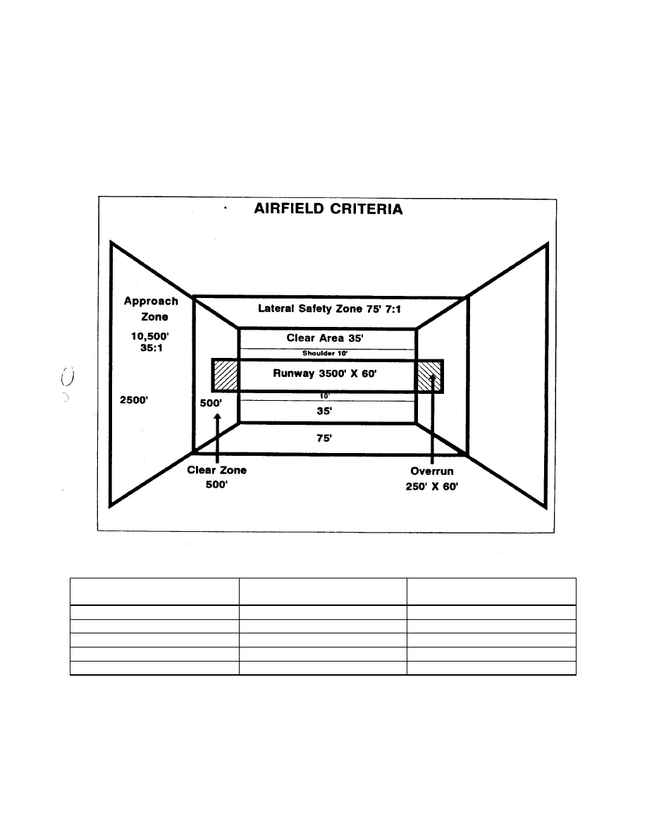
Marine Air Traffic Control Mobile Team
TACSOP
6. TAXIWAYS -
WIDTH
60
50 50
30
TURN RADIUS
100
75 75 70
CLEAR AREA
135
75 75
65
RUT DEPTH
AIRCRAFT LOADING
NUMBER OF LANDINGS &
TAKE OFFS
0.00”
EMPTY
100
0.10”
EMPTY
10 (UP TO 100 W/RISK)
0.25”
EMPTY
1
0.00”
FULL (155,000 lb.)
10
0.10”
FULL (155,000 lb.)
0
E-6

Marine Air Traffic Control Mobile Team
TACSOP
TYPE A/C
LENGTH
NO OF TURNS
WIDTH
180 deg TURN
3 PT TURN
C-130
3000’
3500’ normal
60 ft
60 ft
50 ft
60 ft normal
C-141
6000 ft
98 ft
138 ft
N/A
C-5
6000 ft
150 ft
150 ft
N/A
C-17
3000’
3500’ normal
90 ft
132 ft
80 ft
90 ft normal
DISTANCE FROM INNER EDGE TO OUTER EDGE
OF THE LATERAL SAF ETY ZONE
MAXIMUM HEIGHT ALLOWED
FOR OBSTACLES
7 feet
1 foot
14 feet
2 feet
21 feet
3 feet
28 feet
4 feet
35 feet
5 feet
42 feet
6 feet
49 feet
7 feet
56 feet
8 feet
63 feet
9 feet
70 feet
10 feet
75 feet
10 feet, 8.5 inches
DISTANCE FROM INNER EDGE TO OUTER
EDGE OF THE APPROACH ZONE
MAXIMUM HEIGHT ALLOWED FOR
OBSTACLES
0 feet
14 feet, 3.5 inches
375 feet
25 feet
1075 feet
45 feet
1775 feet
65 feet
2475 feet
85 feet
3175 feet
105 feet
3875 feet
125 feet
4575 feet
145 feet
5275 feet
165 feet
5975 feet
185 feet
6675 feet
205 feet
7375 feet
225 feet
8075 feet
245 feet
8775 feet
265 feet
9475 feet
285 feet
10175 feet
305 feet
10500 feet
314 ft, 3.5 inches
E-7

Marine Air Traffic Control Mobile Team
TACSOP
APPENDIX E
TLZ PILOT BRIEF
1. LOCATION (PRIMARY AND ALTERNATE)
2. TIME ESTABLISHED AND DURATION
3. CONTROL POINTS
4. INGRESS AND EGRESS ROUTES
5. APPROACH, MISSED APPROACH AND DEPARTURE PROCEDURES
6. SVFR PROCEDURES
7. TLZ HEADINGS AND MARKINGS
8. OBSTACLES
9. NAVAIDS
10. MMT LOCATION
11. FREQUENCIES, CALLSIGNS, VISUAL SIGNALS AND BREVITY CODES
12. EMERGENCIES
E-8
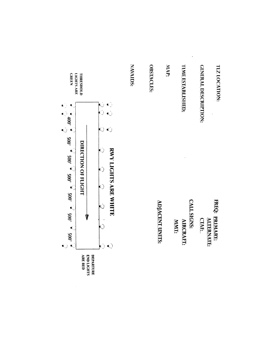
Marine Air Traffic Control Mobile Team
TACSOP
APPENDIX E
NIGHT TLZ BRIEF SHEET
T
E-9
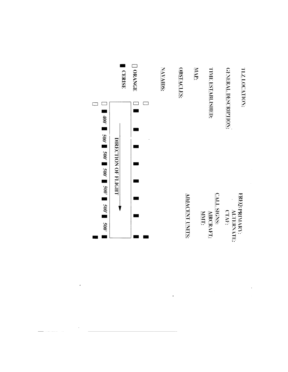
Marine Air Traffic Control Mobile Team
TACSOP
APPENDIX E
DAY TLZ BRIEF SHEET
E-10

Marine Air Traffic Control Mobile Team
TACSOP
APPENDIX E
TLZ EXECUTION CHECKLIST
(EXAMPLE)
LINE# EVENT
NET
FROM
TO CODE TIME
1
MMT AT AIR SITE MMT HOOSIERS
2
C130 ON STATION C130
MMT FALCONS
3
C130 BEGIN APPROACH MMT C130 TARHEELS
4
TLZ LIGHTS ON
C130
MMT RAZORBACKS
5
C130 ON DECK MMT
SPARTANS
6
C130 RDY FOR DEP C130 MMT BADGERS
7
MMT RDY FOR EXTRACT MMT
VOLUNTEERS
8
MISSION COMPLETE MMT
SOONERS
9
10
11
12
13
15
16
17
18
19
20
21
22
23
24
25
26
27
28
29
30
31
32
33
ALTERNATE PLAN
CAVALIERS
34
LZ HOT
DEVILS
35
TIME LINE CHANGE
SEIKO (+/-)
E-11
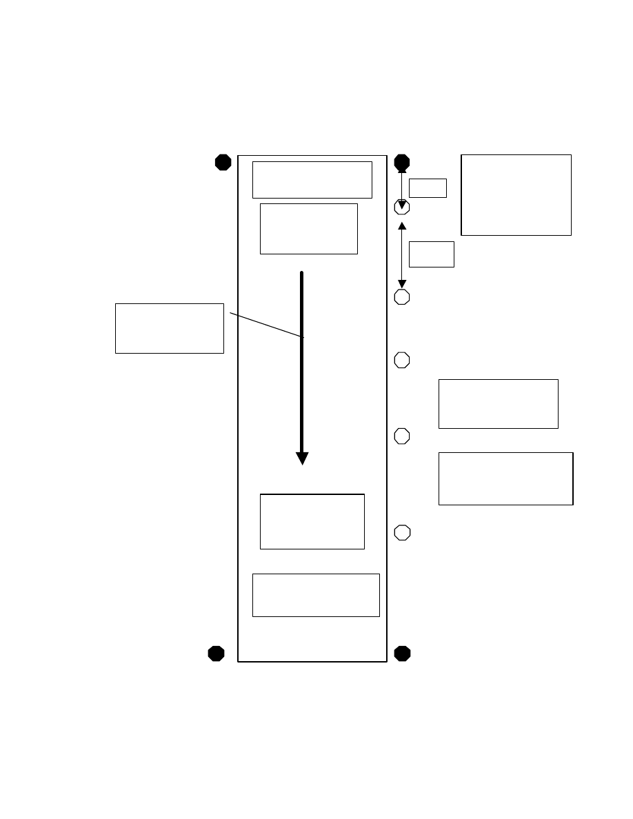
Marine Air Traffic Control Mobile Team
TACSOP
APPENDIX E
TLZ AMP-2
E-12
RWY
DIMENSIONS
3500’ X 60’
500’
1000’
REMAINING
LIGHTS
500’ APART
DEPARTURE
LIGHTS ARE RED.
APPROACH
LIGHTS GREEN
TPN-30/PPN-19
100’ FROM APP.
END AND 30’
MIN. OFFSET
RUNWAY
LIGHTS
WILL BE WHITE.
SETUP FOR DAY
OPS SUBSTITUTE
PANELS FOR LIGHTS
DIRECTION
OF
FLIGHT
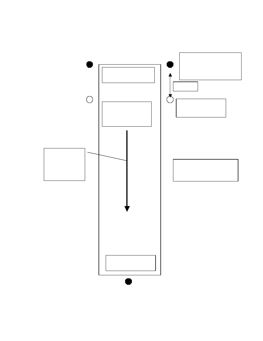
Marine Air Traffic Control Mobile Team
TACSOP
APPENDIX E
TLZ AMP-3
E-13
APPROACH LIGHTS
GREEN
500’
RUNWAY
DIMENSIONS
3500’ X 60’
TOUCHDOWN
LIGHTS WHITE
DAYTIME SETUP
SUBSTITUTE PANELS
FOR LIGHTS.
DEPARTURE END
LIGHT RED.
TPN-30/PPN-19 100’
FROM APP. END AND
30’ MIN. OFFSET.
DIRECTION
OF
FLIGHT

Marine Air Traffic Control Mobile Team
TACSOP
THIS PAGE INTENTIONALLY LEFT BLANK

Marine Air Traffic Control Mobile Team
TACSOP
APPENDIX F
HLZ PLANNING CHECKLIST
1. LOCATION -
PRIMARY
ALTERNATE
2. INTELLIGENCE -
PHOTO RECONNAISSANCE
SIZE
SLOPE
SURFACE TYPE AND MATERIAL
PROMINENT TERRAIN FEATURES
OBSTRUCTIONS AND HEIGHTS
3. OPERATIONS -
TYPE AND NUMBER OF AIRCRAFT
LANDING POINT SPACING
TRAFFIC AND WAVE-OFF PATTERNS
DURATION OF OPERATIONS
CONTROL AGENCY AND LOCATION
DAY OR NIGHT
MARKING AIDS AND PATTERNS
INGRESS/EGRESS ROUTES
CONTROL POINTS
SVFR PROCEDURES
DECONFILICTION PLAN
4. THREAT -
GROUND
AIR
AIR DEFENSE
5. BASE DEFENSE ZONE -
GROUND
AIR DEFENSE
RULES OF ENGAGEMENT
6. COMMUNICATIONS -
NETS
FREQUENCIES
F-1

Marine Air Traffic Control Mobile Team
TACSOP
CALLSIGNS
EMCON
ENCRYPTION
VISUAL SIGNALS
7. EMERGENCY PROCEDURES -
TRAP
CASEVAC
F-2

Marine Air Traffic Control Mobile Team
TACSOP
APPENDIX F
HLZ PILOT BRIEF
1. LOCATION (PRIMARY AND ALTERNATE)
2. TIME ESTABLISHED AND DURATION
3. CONTROL POINTS AND INGRESS POINTS
4. SITE HEADINGS AND MARKINGS
5. HLZ SIZE AND SURFACE MATERIAL
6. APPROACH/DEPARTURE CORRIDORS AND OBSTACLES
7. SVFR PROCEDURES
8. MMT LOCATION
9. FREQUENCIES, CALLSIGNS, VISUAL SIGNALS AND BREVITY CODES
10. EMERGENCY PROCEDURES
F-3

Marine Air Traffic Control Mobile Team
TACSOP
APPENDIX F
HLZ EXECUTION CHECKLIST
(EXAMPLE)
LINE# EVENT
NET FROM TO CODE TIME
1
MMT AT AIR SITE
MMT HOOSIERS
2
HLZ ESTABLISHED MMT LONGHORNS
3
HELOS MAKE APPROACH MMT HELOS TARHEELS
4
HELOS ON DECK MMT SPARTANS
5
MMT RDY FOR EXTRACT MMT
VOLUNTEERS
6
MISSION COMPLETE MMT
SOONERS
7
8
9
10
11
12
13
14
15
16
17
18
19
20
21
22
23
24
25
26
27
28
29
30
31
32
33
ALTERNATE PLAN
CAVALIERS
34
LZ HOT DEVILS
35
TIME LINE CHANGE SEIKO (+/-)
F-4
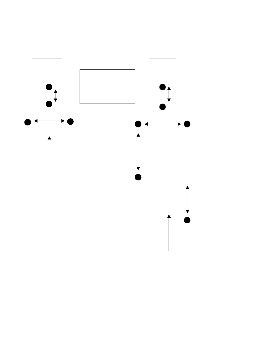
Marine Air Traffic Control Mobile Team
TACSOP
APPENDIX F
NATO Y NATO Y
SINGLE SHIP MULTI-SHIP
50 METERS
APPROACH PATH
50 METERS
APPROACH PATH
NOTE: SPECIFIC AIRCRAFT MAY REQUIRE LARGER DISTANCES BETWEEN LIGHTS
OR MARKER PANELS. DIFFERENT SETUPS MAY BE USED WHEN MMT AND ACE ARE
IN CONCURRENCE.
F-5
STEM SEGMENTS
MUST BE 7 METERS
APART.
LEGS OF Y MUST BE
14 METERS APART.
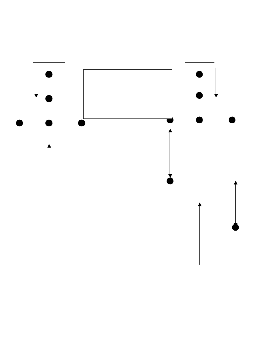
Marine Air Traffic Control Mobile Team
TACSOP
APPENDIX F
“T” “T”
SINGLE SHIP MULTI-SHIP
WIND DIRECTION WIND DIRECTION
50 METERS
50 METERS
APPROACH PATH
APPROACH PATH
NOTE: SPECIFIC AIRCRAFT MAY REQUIRE LARGER DISTANCES BETWEEN LIGHTS
OR MARKER PANELS. DIFFERENT SETUPS MAY BE USED WHEN MMT AND ACE ARE
IN CONCURRENCE.
F-6
LIGHTS IN STEM MUST BE AT
LEAST 8 METERS APART. LIGHTS
AT HEAD OF “T” AT LEAST 5
METERS APART. OFFSET
ADDITIONAL AIRCRAFT BY AT
LEAST 50 METERS.

Marine Air Traffic Control Mobile Team
TACSOP
APPENDIX G
RGR PLANNING CHECKLIST
1. LOCATION (PRIMARY/ALTERNATE) -
TLZ SURVEY INFORMATION
COORDINATES
AREA DESCRIPTION
OBSTACLES
ELEVATION
SLOPE
2. SET-UP -
NUMBER OF POINTS
TYPE OF RGR
GALLONS REQUIRED (OFFLOAD)
PUMPING START/END TIME
BREAKDOWN TIME
RGR HEADING
ZONE MARKINGS
TRAFFIC AND WAVE-OFF PATTERNS
PERSONNEL -
MMT
TAFDS
ORDNANCE
GROUND SECURITY
AIR DEFENSE
MMT LOCATION
3. PRE-STAGING, POST -STAGING AND ARM/DE-ARM AREAS -
LOCATION OF EACH
SPACING OF EACH
MARKING OF EACH
HEADING OF EACH
LOCATION OF BUILT-UP ORDNANCE
4. MOVEMENT AT RGR SITE -
NUMBER AND TYPE AIRCRAFT EXPECTED AND ETA
PRIORITY OF AIRCRAFT
PATTERN
PROCEDURES -
INGRESS POINTS
APPROACH, MISSED APPROACH AND DEPARTURE
SVFR
STAGING AREAS
G-1

Marine Air Traffic Control Mobile Team
TACSOP
TROOP DEBARK/EMBARK
REFUELING POINTS
SCATTER PLAN
5. GROUND BASED AIR DEFENSE -
SET UP IN OR OUT OF ENGAGEMENT ZONE
LOCAL GROUND SECURITY
AIR DEFENSE
6. COMMUNICATIONS -
FREQUENCIES
CALLSIGNS
VISUAL SIGNALS
7. EMERGENCIES -
WAVE OFFS
FIRES
TRAP
8. FUEL PLANNING GUIDE -
a. JP-5 = 6.8 lbs. PER GALLON
b. JP-8 = 6.8 lbs. PER GALLON
c. AIRCRAFT CAPACITY -
AIRCRAFT CAPACITY(lbs) FUEL FLOW(lbs/hr) TIME
CH-46 4,400 1,200
1+40
CH-53D 12,500 2,000 5+00
CH-53E 15,545 3,100 4+30
AH-1 2,100 850 2+15
UH-1 1,350 700 1+50
KC-130F TANKER 62,000 5,000 per hour airborne
CARGO 2,000 5,000 “ “
KC-130R TANKER 75,000 5,000 “ “
CARGO 60,000 5,000 “ “
G-2

Marine Air Traffic Control Mobile Team
TACSOP
APPENDIX G
RGR PILOT BRIEF
1. LOCATION (PRIMARY AND ALTERNATE)
2. TIME ESTABLISHED AND DURATION
3. CONTROL POINTS
4. INGRESS AND EGRESS ROUTES
5. APPROACH, MISSED APPROACH AND DEPARTURE PROCEDURES
6. SVFR PROCEDURES
7. SITE LAYOUT, MARKINGS AND HEADINGS
8. PATTERNS AND MOVEMENT IN SITE
9. FUEL AND ORDNANCE AVAILABLE
10. FREQUENCIES, CALLSIGNS AND VISUAL SIGNALS
11. EMERGENCY PROCEDURES
12. RESTRICTIONS
G-3

Marine Air Traffic Control Mobile Team
TACSOP
APPENDIX G
RGR EXECUTION CHECKLIST
(EXAMPLE)
#
EVENT
NET
FROM
TO
CODE
TIME
1
MMT AT AIR SITE
MMT
HOOSIERS
2
HLZ ESTABLISHED
MMT
LONGHORNS
3
HELOS MAKE
APPROACH
MMT HELOS
TARHEELS
4
HELOS ON DECK
MMT
SPARTANS
5
MMT RDY FOR
EXTRACT
MMT
VOLUNTEERS
6
MISSION
COMPLETE
MMT
SOONERS
7
8
9
10
11
12
13
14
15
16
17
18
19
20
21
22
23
24
25
26
27
28
29
30
31
32
33
ALTERNATE PLAN
CAVALIERS
34
LZ HOT
DEVILS
35
TIME LINE CHANGE SEIKO
G-4

Marine Air Traffic Control Mobile Team
TACSOP
APPENDIX H
COMMUNICATIONS
PRC-104 INFORMATION
EQUIPMENT DATA
FREQUENCY RANGE 2 TO 29.9999 MHz
CHANNEL SPACING
100 Hz
MODULATION
AM
POWER OUTPUT
20 WATTS
ANTENNAS
10' MULTISECTION WHIP
ANY HF ANTENNA
DISTANCE RANGE
10 Mi/16 Km W/10' WHIP
CONDITION DEPENDENT
POWER SOURCE AND LIFE
TWO BA-5590 (3 DAYS)
OPERATING WEIGHT
17 LBS.
SET-UP AND OPERATING PROCEDURES
1. ENSURE THE RADIO IS SWITCHED OFF
2. INSTALL BATTERY
3. ATTACH REQUIRED ANTENNA
4. ATTACH THE HANDSET
5. SET THE FUNCTION SWITCH TO V/TR
6. SET THE MODE SWITCH TO USB
7. SET THE ANTENNA TO THE DESIRED POSITION
8. SELECT THE DESIRED FREQUENCY
9. SWITCH THE RADIO ON (DIAL LIGHT SHOULD COME ON)
10. PRESS AND RELEASE PTT SWITCH TO TUNE ANTENNA
11. ADJUST VOLUME CONTROL KNOB
TEST PROCEDURE
1. SET UP RADIO AS NORMAL
2. SELECT FREQUENCY TO 2221.2 KHz (USB)
3. PRESS AND RELEASE PTT SWITCH TO TUNE ANTENNA
4. TRANSMIT TO ANOTHER HF RADIO
5. CARRY OUT STEPS 1 TO 4 ON THE FOLLOWING FREQUENCIES:
334.3 KHz (LSB) 6665.6 KHz (USB) 8889.8 KHz (LSB)
15554.5 KHz (USB) 27778.7 KHz (LSB)
6. SELECT STANDARD TIME BROADCAST FREQUENCIES 5, 10, 15, 20, AND 25 MHz.
ATTEMPT ALL TO GET THE BEST SIGNAL. MONITOR THE BEST SIGNAL AND SWITCH
SIDEBANDS TO VERIFY THAT THE AUDIBLE SIGNAL DOES NOT CHANGE, INDICATING
THE FREQUENCY ACCURACY OF THE RADIO IS WITHIN SPECIFICATION.
H-1

Marine Air Traffic Control Mobile Team
TACSOP
APPENDIX H
PRC-113 INFORMATION
EQUIPMENT DATA
FREQUENCY RANGE
116.000 TO 149.975 MHz (VHF)
225.000 TO 399.975 MHz (UHF)
CHANNEL SPACING
25 KHz
MODULATION
AM
POWER OUTPUT
2 WATTS (LOW POWER)
10 WATTS (HIGH POWER)
ANTENNAS
UHF/VHF COMBINED
DISTANCE RANGE
2 Mi/1.2 Km (LOW POWER)
10 Mi/16 Km (HIGH POWER)
POWER SOURCE AND LIFE
BA-5590 (24 HOURS)
OPERATING WEIGHT
14 LBS.
PRESET CHANNELS
8
SET-UP AND OPERATING PROCEDURES
1. ENSURE THE RADIO IS SWITCHED OFF
2. INSTALL BATTERY
3. ATTACH ANTENNA
4. ATTACH THE HANDSET
5. SWITCH THE RADIO ON
6. SET FREQUENCY ON KEYPAD BY PRESSING NUMBERS THEN "ENT"
7. PUSH THE PTT SWITCH ON THE HANDSET RELEASE AND LISTEN
8. ADJUST THE VOLUME CONTROL KNOB TO DESIRED LEVEL
9. ADJUST THE SQUELCH CONTROL KNOB TO ELIMINATE RUSHING NOISE
PRESET CHANNELS
1. SET THE FREQUENCY ON KEYPAD BY PRESSING NUMBERS THEN "PST"
2. THE DISPLAY WILL SHOW "LP -" THEN PRESS 1 - 8 FOR CHANNEL NUMBER
3. PRESS "ENT" TO LOAD INTO MEMORY
4. CHECK FOR PROPER FREQUENCY NOW SHOWN IN DISPLAY WINDOW
5. REPEAT FOR EACH PRESET CHANNEL
6. SELECT THE PRESET CHANNEL BY PRESSING "PST", THE CHANNEL NUMBER AND
"ENT"
HAVE QUICK SET -UP
1. LOAD WOD IN PRESETS 15 TO 20 AS DESCRIBED ABOVE
2. SET RADIO TO NET STATION FREQUENCY
H-2

Marine Air Traffic Control Mobile Team
TACSOP
APPENDIX H
3. NET CONTROL STATION ONLY WILL PRESS "3" THEN "ENT" TO SET EMERGENCY
CLOCK
4. NET STATIONS PRESS "TOD" TO RECEIVE TOD WHILE NET CONTROL PRESSES "DF"
TO SEND TOD (DISPLAY WILL SHOW "2. tod" OR "3. tod" WHEN RECEIVED)
5. PRESS "ACT" TO SET IN HAVE QUICK OPERATION MODE
6. ALL STATIONS WILL CHECK IN WITH NET CONTROL
PRC-119 INFORMATION
EQUIPMENT DATA
FREQUENCY RANGE
30.000 MHz TO 87.975 MHz
CHANNEL SPACING
25 KHz
MODULATION
FM
POWER OUTPUT
500 MICROWATTS (LOW POWER)
160 MILLIWATTS (MEDIUM POWER)
4 WATTS (HIGH POWER)
50 WATTS (POWER AMPLIFIER)
ANTENNAS
FM/VHF COMBINED
DISTANCE RANGE
0-330 YARDS (LOW POWER)
330 YARDS – 2 MILES (MEDIUM POWER)
2.5 MILES – 5 MILES (HIGH POWER)
22 MILES – POWER AMPLIFIER
POWER SOURCE AND LIFE
BA-5590 (24 HOURS)
OPERATING WEIGHT
22 LBS. W/ BATTERIES
PRESET CHANNELS
8 SINGLE CHANNEL
6 FREQUENCY HOPPING MODE
COMSEC SINGLE CHANNEL OPS - KYK-13,
KYX-15 OR KOI-18
FREQUENCY HOPPING OR SINGLE
CHANNEL – DTD
PRC-117F INFORMATION
EQUIPMENT DATA
FREQUENCY RANGE
30.000 - 89.999990 MHz (VHF Low)
90.000 – 224.999990 MHz (VHF High)
225.000 – 512 MHz (UHF)
243.000 – 270.000 (UHF SATCOM)
292 – 318 MHz (UHF SATCOM)
CHANNEL SPACING
VHF Low 25 kHz
VHF High 5 or 6.25 kHz
UHF 5 kHz
POWER OUTPUT
VHF – 1-10 Watts
UHF – 2-20
H-3

Marine Air Traffic Control Mobile Team
TACSOP
APPENDIX H
ANTENNAS
VHF/UHF COMBINED
POWER SOURCE AND LIFE
BA-5590 (24 HOURS)
OPERATING WEIGHT
15.9 LBS. W/ BATTERIES
PRESET CHANNELS
10 FULLY PROGRAMMABLE
COMSEC EMBEDDED COMSEC CAPABILITY
FILL DEVICES - KYK-13, KYX-15
KOI-18. CYZ-10 DTD
FREQUENCY HOPPING OR SINGLE
CHANNEL
HAVE QUICK I/II UHF ECCM
KYK-13/KOI-18 INSTRUCTIONS
LOADING KYK-13 WITH KOI 18
1. ENSURE BATTERIES ARE LOADED INTO BOTH DEVICES
2. CONNECT KOI-18 TO KYK-13
3. TURN KYK-13 SWITCH TO "ON" AND SELECT REGISTER TO BE FILLED
4. PRESS AND RELEASE KYK-13 INITIATE BUTTON
5. PULL TAPE THROUGH KOI-18 AT A STEADY RATE; RED LIGHT SHOULD FLASH IF
VARIABLE RECEIVED
6. TURN KYK-13 SWITCH TO "OFF/CHECK"; PRESS AND RELEASE INITIATE BUTTON; IF
RED LIGHT FLASHES ON RELEASE, VARIABLE IS PRESENT
7. LOAD OTHER VARIABLES TO OTHER REGISTERS
8. DISCONNECT KOI-18 FROM KYK-13
LOADING KY-57
1. ENSURE BATTERIES ARE LOADED IN KY-57
2. TURN ON KY-57
3. PULL AND TURN MODE SWITCH TO "C" (CIPHER)
4. A CONTINUOUS AUDIBLE ALARM TONE SHOULD BE HEARD IN THE HANDSET;
PRESS AND RELEASE PTT SWITCH TO CLEAR ALARM
5. TURN KY-57 TO "LD" (LOAD)
6. CONNECT KYK-13 IN "OFF" POSITION OR KOI-18 WITH ADAPTER CABLE TO KY-57
7. TURN KY-57 TO REGISTER TO BE FILLED
8. KYK-13: TURN KYK-13 TO "ON" POSITION TO REGISTER OF FILL KOI-18: INSERT
TAPE LEADER INTO KOI-18
9. KYK-13: PRESS AND RELEASE PTT SWITCH; BEEP AND RED LIGHT FLASH ON KYK-
13 INDICATES TRANSFER OF VARIABLE KOI-18: PRESS AND RELEASE PTT SWITCH;
PULL TAPE AT STEADY RATE ALARM WILL STOP ON GOOD TRANSFER
10. REPEAT STEPS 6 TO 9 TO FILL ADDITIONAL REGISTERS
11. DISCONNECT LOADER AND SWITCH KY-57 TO "C"
12. CONNECT KY-57 TO RADIO
H-4

Marine Air Traffic Control Mobile Team
TACSOP
APPENDIX H
PPN-19 INFORMATION
EQUIPMENT DATA
FREQUENCY RANGE
I BAND
J BAND
MODULATION
PULSE
POWER OUTPUT
200 WATTS
DISTANCE RANGE LINE OF SIGHT
POWER SOURCE
BA-5590
ANY EXTERNAL DC 17 TO 30 VOLTS
ANTENNA SET UP AND OPERATION
1. ENSURE SET IS SWITCHED OFF
2. CONNECT POWER SOURCE
3. REMOVE DESIRED ANTENNA FORM STORAGE AREA AND REMOVE SWITCH CAP
FOR TOP OF TRANSPONDER CASE
4. POSITION ANTENNA TO MATCH KEY WITH KEY SLOT AND TIGHTEN; PLACE SWITCH
CAP IN STORAGE AREA
5. SET POWER TO "INTL"
6. SET MODE TO "STBY"
7. SELECT CODE (A TO G) AND FREQUENCY BAND (I, J, I+J, OR GAR-I)
(USMC KC-130 UTILIZE “I” BAND)
8. OMNIDIRECTIONAL: SET AGC SWITCH TO "OFF" DIRECTIONAL: SET AGC SWITCH
TO "ON"
9. SET MONITOR MODE SWITCH TO "XMT"
10. SET MODE SWITCH TO "NORM"; TRANSPONDER WILL BE OPERABLE IN 3O
SECONDS
11. AFTER TRANSMISSION IS COMPLETE, SET MODE SWITCH TO "STBY 1" TO
CONSERVE BATTERIES
REMOTE CONTROL OPERATION
1. CONNECT REMOTE CONTROL ASSEMBLY TO UNIT WITH UP TO 50 METERS OF
SLASH WIRE
2. SET POWER SWITCH TO "INTL"
3. SET REMOTE CONTROL ON/OFF SWITCH TO "ON"
4. IF MODE SWITCH IS SET TO "STBY", SET WILL REPLY TO INTERROGATION AT 30
SECONDS; IF MODE SWITCH IS SET TO "NORM", SET WILL REPLY INSTANTANEOUSLY
5. AFTER TRANSMISSION IS COMPLETE, SET REMOTE CONTROL SWITCH TO "OFF"
H-5

Marine Air Traffic Control Mobile Team
TACSOP
APPENDIX H
QUARTER WAVELENGTH ANTENNAS
FREQ
LENGTH
FREQ
LENGTH
(MHz)
(FEET)
(MHz)
(FEET)
2.0 117.0
12.0
19.5
2.2 106.0 13.0
18.0
2.4
97.5
14.0
16.7
2.6
90.0
15.0
15.6
2.8
83.5
16.0
14.6
3.0
78.0
17.0
13.7
3.3
70.9 18.0
13.0
3.6
65.0 19.0
12.3
4.0
58.5
20.0
11.7
4.5
52.0
21.0
11.1
5.0
46.8
22.0
10.6
5.5
42.5
23.0
10.1
6.0
39.0
24.0
9.7
6.5
36.0
25.0
9.3
7.0
33.4
26.0
9.0
8.0
29.2
27.0
8.6
9.0
26.0
28.0
8.3
10.0
23.4
29.0
8.0
11.0
21.2
30.0
7.8
H-6

Marine Air Traffic Control Mobile Team
TACSOP
APPENDIX H
ACE COMMUNICATION NET DESCRIPTIONS
ACE COMMAND NET (HF) (ACE CMD) - PROVIDES A PATH FOR THE COMMANDER TO
EXERCISE COMMAND OF SUBORDINATE UNITS.
ACE COMM COORDINATION NET (HF) (COM COORD) - PROVIDES A MEANS FOR THE
COMMUNICATORS TO ENGINEER, MANAGE AND RESTORE THE ACE'S
COMMUNICATIONS SYSTEM.
AIR DEFENSE ALERT NET (UHF) (ADA) - PROVIDES A MEANS FOR AIR DEFENSE
SYSTEMS TO PASS EARLY WARNING INFO, TO INCLUDE LEAKER CALLS.
AIR OPS CONTROL NET (HF/MUX) (AOC) - PROVIDES A MEANS FOR THE TAOC TO
REQUEST AAW ASSETS AND UPDATE THE TACC ON AAW ISSUES.
ANTIAIRCRAFT CONTROL NET (MUX/HF) (AAC) - PROVIDES A MEANS TO CONTROL
HAWK F.P.s INFO PASSED INCLUDES: TARGET ASSIGNMENTS, FIRE CNTL ORDERS,
WPNS CNTL STATUSES, ETC...
ANTIAIRCRAFT INTELLIGENCE (MUX/HF) (AAI) - PROVIDES A MEANS TO PASS EARLY
WARNING INFO BTW TAOC/EWC AND HAWK F.P.s
APPROACH CONTROL NET (UHF/VHF) (APP/CNTL) - PROVIDES A MEANS FOR THE
MATCD TO COORDINATE RADAR TRAFFIC INTO THE TERMINAL AIRSPACE. MAY
REQUIRE MULTIPLE NETS.
COMMAND ACTION NET (HF/MUX) (CA) - PROVIDES A MEANS FOR THE TAC TO
COORDINATE AAW ISSUES WITH THE SAAWC.
COMBAT INFO/DETECTION (HF/MUX) (CID) - PROVIDES A MEANS FOR REPORTING ON
UNIDENTIFIED AND HOSTILE A/C.
CRASH FIRE AND RESCUE (VHF) (CFR) - PROVIDES A MEANS TO COORDINATE CRASH
RECOVERIES ON OR AROUND THE AIRFIELD.
DATALINK COORD NET (MUX/UHF/HF) (DCN) - PROVIDES A MEANS FOR MAINTENANCE
COORDINATION OF DATALINK OPERATIONS. MAY BE COMBINED WITH TSN. USUALLY
ONE PER DATALINK (I.E. MUX TADIL B, HF TADIL A ETC.)
DEPARTURE CONTROL NET (UHF/VHF) (DEP/CNTL) - PROVIDES A MEANS TO
COORDINATE RADAR TRAFFIC OUT OF THE TERMINAL AIRSPACE. MAY REQUIRE
MULTIPLE NETS.
H-7

Marine Air Traffic Control Mobile Team
TACSOP
APPENDIX H
ACE COMMUNICATION NET DESCRIPTIONS
DIRECT AIR SUPPORT NET (HF/MUX) (DAS) - PROVIDES A MEANS FOR THE DASC TO
REQUEST DIRECT AIR SUPPORT AIRCRAFT FROM THE TACC AND PROVIDE UPDATED
INFO ON MISSIONS.
FIRE DIRECTION NET (VHF/HF) (FD) - PROVIDES A MEANS TO PASS EARLY WARNING
AND CUEING FROM THE FIRING PLATOONS TO THE CONTINGENCY FIRE UNITS AND
SENSOR ACQUISITION SECTIONS.
FIGHTER AIR DIRECTION NET (UHF/VHF) (FAD) - PROVIDES A MEANS FOR AGENCIES
TO CONTROL FIGHTER AIRCRAFT MANNING COMBAT AIR PATROLS.
GROUND BASED DATALINK (VHF/FREQ HOP) (GBDL) - PROVIDES A MEANS TO PASS
EARLY WARNING INFO AND FIRE CONTROL ORDERS BTW HAWK FP AND CFUs; SAS
AND CFU; AND SAS AND LAAD ELEMENTS. CURRENTLY USED WITH WPNS DIRECTOR
UNITS.
GROUND CONTROL APPROACH NET (VHF/UHF) (GCA) - PROVIDES A MEANS FOR
GROUND CONTROL APPROACH BEARING AND ALTITUDE INFO TO A/C.
GROUND CONTROL NET (UHF/VHF) (GRND/CNTL) - PROVIDES A MEANS FOR THE
GROUND CONTROLLER TO COORDINATE MOVEMENT OF ALL GROUND AIRCRAFT,
VEHICLES, AND PERSONNEL ON TAXIWAYS AND RUNWAYS. MULTIPLE NETS MAY BE
REQUIRED.
GROUP COMMON (UHF/VHF) (GRP CMN) - PROVIDES A MEANS FOR GROUP
HEADQUARTERS TO COORDINATE WITH AIRBORNE AIRCRAFT. EACH AIRCRAFT IS
ASSIGNED ITS OWN.
GUARD (UHF/VHF) (GRD) - PROVIDES AN EMERGENCY DISTRESS NET USED BY
AIRCRAFT AND CONTROL AGENCIES.
HANDOVER/CROSSTELL NET (HF/MUX) (H/O XTEL) - PROVIDES A MEANS FOR THE
EXCHANGE OF A/C CONTROL BETWEEN AIR CONTROL AGENCIES.
HELICOPTER DIRECTION NET (UHF/VHF/HF) (HD) - PROVIDES A MEANS TO CONTROL
HELOS WITHIN THE OBJECTIVE AREA.
HELICOPTER REQUEST NET (HF/UHF) (HR) - PROVIDES A MEANS FOR REQUESTING
IMMEDIATE HELO SUPPORT IN AMPHIBIOUS OPS.
INTERFACE COORD NET (HF/UHF/MUX) (ICN) - PROVIDES A MEANS FOR COMMAND
LEVEL COORD OF JOINT DATALINK EMPLOYMENT.
H-8

Marine Air Traffic Control Mobile Team
TACSOP
APPENDIX H
ACE COMMUNICATION NET DESCRIPTIONS
LAAD BATTALION COMMAND (HF) (LBC) - PROVIDES A MEANS FOR THE PASSAGE OF
ADMIN AND LOGISTICS SUPPORT BTW BN HQ AND SUBORDINATE BATTERIES.
LAAD COMMAND (HF) (LC) - PROVIDES A MEANS FOR THE COMMANDER TO PASS
ADMIN AND LOGISTICS INFO, AND TO EXERCISE TACTICAL EMPLOYMENT OF LAAD
PLTS.
LAAD TEAM CONTROL NET (VHF) (LTC) - PROVIDES A MEANS FOR THE PASSAGE OF
CRITICAL AIR DEFENSE INFO BTW SECT LDRS AND TEAMS.
LAAD WEAPONS CONTROL NET (HF) (LWC) - PROVIDES A MEANS FOR THE PASSAGE
OF CRITICAL AIR DEFENSE INFO BTW PLT CDRS AND SECTION LEADERS.
LZ CONTROL NET (UHF/VHF) (LZ CNTL) - PROVIDES A MEANS FOR THE LZ CONTROL
TEAM TO CONTROL AIRCRAFT EN ROUTE FROM THE INITIAL POINT TO THE LANDING
ZONE. MULTIPLE NETS REQUIRED.
MAGTF COMMAND NET (HF/SAT) (MAGTF CMD) - PROVIDES A MEANS FOR THE
COMMANDER TO EXERCISE COMMAND OF SUBORDINATE UNITS.
MAGTF INTELLIGENCE (HF/SAT) (MAGTF INTEL) - PROVIDES A PATH FOR RAPID
COLLECTION & DISSEMINATION OF INTEL AND COMBAT INFO.
MAGTF TACTICAL NET (HF/SAT) (MAGTF TAC) - PROVIDES A PATH FOR TACTICAL
TRAFFIC BETWEEN MAGTF AND SUBORDINATE UNITS.
RADAR REMOTE COORDINATION (VHF/HF) (RRC) - PROVIDES RADAR REMOTE LINKS
BETWEEN EW/C SITES AND THE TAOC.
SEARCH AND RESCUE (UHF/VHF) (SAR) - PROVIDES A MEANS FOR CONTROL AND
COORDINATION OF AIR RESCUE MISSIONS. MULTIPLE NETS ARE REQUIRED.
SQUADRON COMMON NET (UHF/VHF) (SQDN CMN) - PROVIDES A MEANS FOR
SQUADRON HQ TO COORDINATE WITH AIRBORNE AIRCRAFT. EACH SQUADRON IS
ASSIGNED ITS OWN.
H-9

Marine Air Traffic Control Mobile Team
TACSOP
APPENDIX H
ACE COMMUNICATION NET DESCRIPTIONS
TACTICAL AIR COMMAND NET (HF) (TACMD) - PROVIDES A MEANS FOR THE TAC TO
TASK SUBORDINATE UNITS TO MEET THE SIX FUNCTIONS OF MARINE AVIATION.
TACTICAL AIR DIRECTION NET (UHF/VHF) (TAD) - PROVIDES A MEANS FOR THE
DIRECTION OF A/C CONDUCTING OAS MISSIONS. DASC, FAC, FAC(A) AND TAC(A) MAY
REQUIRE OWN NET.
TACTICAL AIR REQUEST NET (VHF/HF) (TAR) - PROVIDES A MEANS FOR GROUND
UNITS TO REQUEST IMMEDIATE AIR SUPPORT FROM THE DASC.
TACTICAL AIR TRAFFIC CONTROL (UHF/VHF) (TATC) - PROVIDES A MEANS FOR
CONTROL AGENCIES TO CONTROL ALL TACTICAL AND ITINERANT AIRCRAFT W/IN
THEIR AREA OF RESPONSIBILITY. EACH AGENCY REQUIRES OWN NET.
TANKER NET (VHF/HF) (TNKR CMN) - PROVIDES A MEANS FOR INFLIGHT REFUELING
A/C TO COMMUNICATE WITH THE TANKER.
TOWER PRIMARY NET (UHF/VHF) (TWR) - PROVIDES A MEANS FOR THE LOCAL
CONTROLLER TO ISSUE TRAFFIC ADVISORIES AND AIRCRAFT CLEARANCES WITHIN
THE CLASS D AIRSPACE. MULTIPLE NETS MAY BE REQUIRED.
TRACK SUPERVISION NET (HF/MUX/UHF) (TSN) - PROVIDES A MEANS FOR TRACK
SURVEILLANCE PERSONNEL TO EXCHANGE INFO TO MAINTAIN A CLEAR RECOGNIZED
AIR PICTURE.
VOICE PRODUCT NET (UHF/HF) (VPN) - TO DISSEMINATE NONDIGITAL SIGINT INFO.
ARMY TACTICAL DATA LINK-1 (MUX) (ADTL-1) - PROVIDES A POINT-TO-POINT
EXCHANGE OF DIGIT AL INFO BTW HAWK FIRING PLATOONS AND THE TAOC OR
AUTOMATED EW/C. FULL DUPLEX.
LINK-1 (NATO) (MUX) (LNK-1) - PROVIDES A MEANS FOR THE TACC AND TAOC TO
EXCHANGE DIGITAL INFO IN A POINT-TO-POINT MODE WITH NADGE AGENCIES.
TADIL A (HF/UHF) (TDL A) - PROVIDES A MEANS TO PASS AUTOMATICALLY
PROCESSED DIGITAL INFO IN A NETTED CONFIGURATION.
TADIL B (CABLE/MUX) (TDL B) - PROVIDES A MEANS TO PASS DIGITAL INFO IN A
POINT-TO-POINT CONFIGURATION.
TADIL C (UHF; 300 - 324.95MHz) (TDL C) - PROVIDES A MEANS TO PASS DIGITAL INFO
BETWEEN THE TAOC AND FIGHTER A/C; AND THE MATCD AND FIGHTER A/C.
H-10

Marine Air Traffic Control Mobile Team
TACSOP
APPENDIX I
STANDARD REPORT FORMATS
CASEVAC REQUEST
A. PRECEDENCE - Urgent: Move immediately to save life or limb.
Priority: Prompt medical care within 24 hrs.
Routine: Minor injury/KIA pickup within 72 hrs.
B. NUMBER OF CASEVACS
C. AIRBORNE MEDICAL ASSISTANCE REQUIRED/NOT REQUIRED
D. PICK-UP COORDINATES
E. LZ FREQUENCIES/CALL SIGN
F. LZ SECURE/UNSECURE
I-1

Marine Air Traffic Control Mobile Team
TACSOP
APPENDIX I
SITREP
A. LOCATION
B. SUMMARY OF LAST 6 HOURS
C. ENEMY CONTACT & COORDINATES
D. SIGNIFICANT EVENTS
E. PLANS FOR NEXT 6 HOURS
F. CASUALTIES IN PAST 6 HOURS
G. FRIENDLY KIA
H. FRIENDLY WIA
I. ENEMY KIA
J. ENEMY WIA
K. ENEMY POW
I-2

Marine Air Traffic Control Mobile Team
TACSOP
APPENDIX I
SPOT REPORT
A. SIZE
B. ACTIVITY
C. LOCATION
D. UNIT
E. TIME
F. EQUIPMENT
G. REMARKS
I-3

Marine Air Traffic Control Mobile Team
TACSOP
APPENDIX I
CASUALTY REPORT
A. MEDEVAC # (INITIAL & LAST 4 DIGITS OF SSN)
B. DTG OF INCIDENT
C. LOCATION
D. TYPE OF WOUND
1. GUNSHOT
2. SHRAPNEL
3. OTHER (SPECIFY)
E. PORTION OF BODY AFFECTED
F. EXTENT OF INJURY
1. NON-SERIOUS
2. SERIOUS
3. DEAD
G. MEDEVAC: (YES/NO)
H. ACTIVITY
1. PATROL
2. OFFENSIVE OPERATION
3. DEFENSIVE OPERATION
4. OTHER (EXPLAIN)
I. CAUSED BY:
1. SNIPER
2. GRENADE
3. MINE
4. BOOBY TRAP
5. INDIRECT FIRE
6. OTHER
I-4

Marine Air Traffic Control Mobile Team
TACSOP
APPENDIX I
ALPHA FORMAT --TLZ SURVEY
A. TLZ NAME
B. LOCATION
C. MAGNETIC RWY HEADING
D. LENGTHS
1. RUNWAY
2. OVERRUN APPROACH END
3. OVERRUN DEPARTURE END
4. TAXIWAY
E. WIDTHS
1. RUNWAY
2. LEFT SHOULDER
3. RIGHT SHOULDER
4. LEFT CLEAR ZONE
5. RIGHT CLEAR ZONE
6. LEFT LATERAL SAFETY ZONE
7. RIGHT LATERAL SAFETY ZONE
8. TAXIWAY
F. SURFACE CONDITION
G. GLIDE SLOPE REQUIRED
H. OBSTRUCTIONS
I. RUNWAY MARKINGS
J. REMARKS
I-5

Marine Air Traffic Control Mobile Team
TACSOP
APPENDIX I
JOINT SPECTRUM INTERFERENCE RESOLUTION (JSIR) REPORT
EXAMPLE FORMAT
(1) Organization affected by EMI. Point of contact information (POC)
(Name and telephone number). Make sure when listing a POC that the individual
is familiar with the problem.
(2) Place name, latitude, and longitude where EMI occurred.
(3) Times, dates, periods EMI occurred. Indicate whether the duration of the
interference is continuous or intermittent, the approximate repetition rate of
interference, and whether the amplitude of the interference is varying or constant.
Indicate if the interference is occurring at a regular or irregular time of day.
(4) Systems and equipment affected by the EMI. Affected system function, name,
nomenclature, manufacturer with model number, or other system description.
(5) Allocated frequency band or authorized frequency of equipment affected.
(6) Station and/or equipment causing the interference and the location or call sign,
if known.
(7) Allocated frequency band or authorized frequency of the station and/or equipment
causing the interference, if known.
(8) Probable cause of interference (for example, co-channel assignment, harmonics,
inter-modulation, spurious products, jamming, etc.).
(9) Extent of impairment to operational capability of affected equipment.
Characteristics of interference (reduced range, false targets, reduced intelligibility,
data errors, etc.)
(10) Corrective measures taken to resolve or work around the interference.
(11) Effect of corrective measures.
(12) Any additional useful remarks. Provide a clear, unstructured narrative summary
on the interference and local actions that have been taken to resolve the
problem.
I-6

Marine Air Traffic Control Mobile Team
TACSOP
APPENDIX J
HELICOPTER OPERATIONS AIDS
HELITEAM LEADER COMMUNICATIONS SLATE
HELITEAM LEADER NAME -
CALLSIGN -
SERIAL ASSIGNMENT NUMBER -
DESIRED LANDING IN LZ -
SECTOR -
GRID COORDINATE -
ALTERNATE LZ IS -
IS LZ HOT - OR COLD -
OUR FREQUENCY IS - BUTTON -
OUR CALLSIGN IS -
WHAT WILL YOUR LANDING DIRECTION BE?
ANY OTHER INFORMATION YOU HAVE?
INFORM ME OF ANY CHANGES
GIVE ME 2 MINUTE AND 1 MINUTE WARNINGS
J-1

Marine Air Traffic Control Mobile Team
TACSOP
APPENDIX J
EMBARKATION CARD FORMAT
MMT EMBARK CARD
NAME: _______________________________ RANK: _________________
SSN: __________________________________ BLD TYP: ______________
ORGANIZATION: _______________________________________________
J-2

Marine Air Traffic Control Mobile Team
TACSOP
APPENDIX K
ACRONYMS/SYMBOLS LIST
A2C2
Army Airspace Command and Control
AA
Air to Air
AAA
Antiaircraft Artillery
AADC
Area Air Defense Commander
AAM
Air to Air Missile
AAW
Antiair Warfare
AAWC
Antiair Warfare Commander (USN)
ABCCC
Airborne Battlefield Command and Control Center
ACA
Airspace Coordination Area
Airspace Control Area
Airspace Control Authority
ACE
Aviation Combat Element
ACEOI
Automated Communications Electronics Operating
Instruction
ACLS
Automatic Carrier Landing System
ACM
Air Combat Maneuver
ACO
Airspace Control Order
ACP
Airspace Control Plan
AD
Aerial Delivery
ADA
Air Defense Alert (Net)
Air Defense Artillery
Air Defense Area
ADS
Airspace Deconfliction System
AEW
Airborne Early Warning
AFL
Assault Flight Leader
AGL
Above Ground Level
A/G
Air to Ground
AGM
Air-to-Ground Missile
AGS
Aviation Ground Support
AI
Airborne Interceptor
AIC
Air Intercept Controller
AIM
Air Intercept Missile
AIO
Air Intelligence Officer
AIZ
Air Intercept Zone
ALO
Artillery Liaison Officer
ALTRV
Altitude Reservation
AMC
Air Mission Commander
Air Mobility Command
AMRAAM
Advanced Medium Range Air to Air Missile
ANVIS
Aviator Night Vision Imaging System
K-1

Marine Air Traffic Control Mobile Team
TACSOP
APPENDIX K
ACRONYMS/SYMBOLS LIST
AO
Aerial Observer
Air Officer
Area of Operation
AOA
Amphibious Objective Area
AOB
Air Order of Battle
Advanced Operations Base
AOR
Area of Responsibility (JFC only)
APU
Auxiliary Power Unit
AR
Aerial Refueling
Area of Responsibility
Armed Reconnaissance
ARCP
Aerial Refueling Control Point
ARCT
Aerial Refueling Control Time
ARG
Amphibious Ready Group
ARM
Antiradiation Missile
ARTY
Artillery
ASC (A)
Assault Support Coordinator (Airborne)
ASCIET
All Service Combat Identification Evaluation
Team
ASE
Aircraft Survivability Equipment
Air Support Element
ASLT
Air Support Liaison Team
ASM
Air-to-Surface Missile
ASR
Assault Support Request
ASW
Antisubmarine Warfare
ATARS
Advanced Tactical Aerial Reconnaissance System
ATBM
Anti-Tactical Ballistic Missile
ATC
Air Traffic Control
ATCF
Air Traffic Control Facility
ATDL-1
Army Tactical Data Link-1
ATDS
Airborne Tactical Data System (E-2)
ATF
Amphibious Task Force
ATGM
Antitank Guided Missile
ATO
Air Tasking Order
AWACS
Airborne Warning And Control System (E-3)
AWC
Assistant Weapons Controller
Bald Eagle
Quick reaction helicopterborne company
Bandit
Known enemy aircraft, does not necessarily
imply clearance to fire.
BARCAP
Barrier Combat Air Patrol
BDZ
Base Defense Zone
Bingo
Fuel Required for ACFT RTB
BLT
Battalion Landing Team
BMNT
Beginning of Morning Nautical Twilight
K-2

Marine Air Traffic Control Mobile Team
TACSOP
APPENDIX K
ACRONYMS/SYMBOLS LIST
Bogey
Radar or visual contact which is unidentified
but assumed to be hostile.
Bump Plan
A contingency plan to replace pilots or
aircraft in the event an aircraft goes down
Buzzer
Slang for electronic jamming
C2 W
Command and Control Warfare
C3
Command, Control and Communications
C3I
Command, Control, Communications and
Intelligence
CAP
Combat Air Patrol
CAS
Close Air Support
CASEVAC
Casualty Evacuation
CATF
Commander Amphibious Task Force
CBR
California Bearing Ratio
CCIR
Commanders Critical Intelligence Requirements
CCM
Counter-Counter Measures
CCS
Command and Control Subsystem
CE
Command Element
CEO
Communications Electronic Officer
CEOI
Communications Electronics Operating
Instruction
CFL
Coordinated Fire Line
CFR
Crash Fire Rescue
Chattermark
Overcoming enemy communications jamming by
switching frequencies using a pre-briefed
frequency rotation plan.
CI
Counter Intelligence
CIC
Combat Information Center
CI/D
Combat Information/Detection (Net)
CINCLANTFLT
Commander-in-Chief, Atlantic Fleet
CINCPACFLT
Commander-in-Chief, Pacific Fleet
CIT
Counterintelligence Team
CLF
Commander Landing Force
CM
Counter Measures
CMCC
Classified Material Control Center
CNX/CANX
Cancel
COC
Combat Operations Center
COMMARFORLANT Commander Marine Forces Atlantic
COMMARFORPAC Commander Marine Forces Pacific
COMINT
Communications Intelligence
COMSEC
Communications Security
CONUS
Continental United States
CP
Control Point
Contact Point
Command Post
K-3

Marine Air Traffic Control Mobile Team
TACSOP
APPENDIX K
ACRONYMS/SYMBOLS LIST
CRP
Combat Readiness Percentage
CSAR
Combat Search and Rescue
CSP
Contingency Support Package
CSSE
Combat Service Support Element
CSS
Combat Service Support
CW
Continuous Wave
CWAR
Continuous Wave Acquisition Radar
DAS
Direct Air Support
Direct Air Support (Net)
Deep Air Support
Direct Access Service
DASC
Direct Air Support Center
DASC(A)
Direct Air Support Center (Airborne)
DEFCON
Defense Readiness Condition
DEFTAC
Defensive Tactics
DF
Direction Finding
DIA
Defense Intelligence Agency
DISUM
Daily Intelligence Summary
DME
Distance Measuring Equipment
DPICM
Dual Purpose Improved Conventional Munitions
DR
Dead Reckoning
DTG
Date-Time-Group
DZ
Drop Zone
EA
Electronic Attack
Engagement Area
EAF
Expeditionary Airfield
ECC
Evacuation Control Center
E&E
Escape & Evasion
EENT
End of Evening Nautical Twilight
EEI
Essential Elements of Information
EFL
Escort Flight Leader
ELINT
Electronic Intelligence
EMCON
Emission Control
EMI
Electromagnetic Interference
EOB
Electronic Order of Battle
Enemy Order of Battle
EP
Electronic Protection
ES
Electronic Warfare Support
ETA
Estimated Time of Arrival
ETE
Estimated Time Enroute
EW
Electronic Warfare
Early Warning
EW/C
Early Warning and Control
FAC
Forward Air Controller
FAC(A)
Forward Air Controller (Airborne)
K-4

Marine Air Traffic Control Mobile Team
TACSOP
APPENDIX K
ACRONYMS/SYMBOLS LIST
FACSFAC
Fleet Area Control and Surveillance Facility
FAD
Fighter Air Direction (Net)
FARP
Forward Arming and Refueling Point
FASCAM
Family of Scatterable Mines
FDC
Fire Direction Center
FDO
Fire Direction Officer
FEBA
Forward Edge of the Battle Area
FEZ
Fighter Engagement Zone
FFA
Free Fire Area
FFCC
Force Fires Coordination Center
FLOT
Forward Line of Own Troops
FO
Forward Observer
FOB
Forward Operating Base
Friendly Order of Battle
FOD
Foreign Object Damage
FOE
Focus of Effort
FSC
Fire Support Coordinator
FSCC
Fire Support Coordination Center
FSCL
Fire Support Coordination Line
FWAR
Fixed Wing Aerial Refueling
GAIL
Glide Angle Indicator Light (GAIL) System
GBAD
Ground Based Air Defense
GBDL
Ground Based Data Link
GCCS
Global Command and Control System
GCE
Ground Combat Element
GPS
Global Positioning System
GSE
Ground Support Equipment
HA
Holding Area
HAC
Helicopter Aircraft Commander
HAO
Humanitarian Assistance Operation
HAR
Helicopter Aerial Refueling
HARM
High Speed Anti-radiation Missile
HAT
Helicopter Availability Table
HCZ
Helicopter Control Zone
HD
Helicopter Direction (Net)
Helicopter Director
HDC
Helicopter Direction Center (USN)
HEALT
Helicopter Employment and Assault Landing
Table
HEDP
High Explosive Dual Purpose
HERO
Hazards of Electromagnetic Radiation to
Ordnance
HERS
Helicopter Expedient Refueling System
HF
High Frequency
K-5

Marine Air Traffic Control Mobile Team
TACSOP
APPENDIX K
ACRONYMS/SYMBOLS LIST
H-Hour
The specific time at which an
operation/exercise commences or is due to
commence.
HIDACZ
High Density Airspace Control Zone
HLA
Helicopter Landing Area
HLZ
Helicopter Landing Zone
HMD DASC
High Mobility Downsized Direct Air Support Center
HMH
Marine Heavy Helicopter Squadron
HML/A
Marine Light Attack Helicopter Squadron
HMM
Marine Medium Helicopter Squadron
HMMWV
High mobility multi-purpose wheeled vehicle
HNVS
Helicopter Night Vision System (CH-53)
Hostile
A known threat Aircraft: implies clearance
to fire
HR
Helicopter Request (Net)
HST
Helicopter Support Team
HUC
Helicopterborne Unit Commander
HUMINT
Human Intelligence; collection by agents
HVA
High Value Asset
HVAA
High Value Airborne Asset
HWSAT
Helicopter Wave and Serial Assignment Table
IADS
Integrated Air Defense System
ICAO
International Civil Aviation Organization
ICN
Interface Coordination Net
ICO
Interface Coordination Officer
Interface Control Officer
IFF
Identification Friend or Foe
IFR
Instrument Flight Rules
IJMS
Interim JTIDS Message Specification
IMC
Instrument Meteorological Conditions
IMINT
Imagery Intelligence
INS
Inertial Navigation System
INTREP
Intelligence Report
INTSUM
Intelligence Summary
IP
Initial Point
IPB
Intelligence Preparation of the Battlespace
IR
Infrared
IRCM
Infrared Countermeasures
IRCCM
Infrared Counter-Counter Measures
ISOPREP
Isolated Personnel Report
IT/ITT
Interrogator/Interrogator Translator Team
ITG
Initial Terminal Guidance
IW
Information Warfare
K-6

Marine Air Traffic Control Mobile Team
TACSOP
APPENDIX K
ACRONYMS/SYMBOLS LIST
Jamming
The deliberate radiation of electromagnetic
energy with the object of degrading the use
of the enemy's electronic equipment.
JADO
Joint Air Defense Operations
JAOC
Joint Air Operations Center
JATF
Joint Amphibious Task Force
JATO
Jet-assisted Takeoff
JDISS
Joint Deployable Intelligence Support System
JEZ
Joint Engagement Zone
JFACC
Joint Force Air Component Commander
JFC
Joint Force Commander
JINTACCS
Joint Interoperability of Tactical Command
and Control Systems
JOG (A,G,R)
Joint Operations Graphic (Scale 1:250,000)
(A=Air, G=Ground, R=Radar)
JSRC
Joint Search and Rescue Center
JSTARS
Joint Surveillance Target Attack Radar
System
JTADS
Joint Tadil-A Distribution Systems
JTAO
Joint Tactical Air Operations
JTAR
Joint Tactical Airstrike Request
Joint Tactical Airlift Request
JTF
Joint Task Force
JTIDS
Joint Tactical Information Distribution
System
KIAS
Knots Indicated Air Speed
Knot
Nautical mile per hour
Knock it off
Immediately cease all training and proceed
as briefed or return to base.
LAAD BN
Low Altitude Air Defense Battalion
LAN
Local Area Network
LAR
Light Armored Reconnaissance
LAV
Light Armored Vehicle
LF
Landing Force
Low Frequency
LFOC
Landing Force Operations Center
LFSP
Landing Force Support Party
LHA
Amphibious Assault Ship (General Purpose)
LHD
Amphibious Assault Ship (Multi Purpose)
L-Hour
The time at which the first helicopter of
the helicopterborne assault wave touches
down in the landing zone.
LIC
Low Intensity Conflict
LOD
Line of Departure
LOI
Letter Of Instruction
K-7

Marine Air Traffic Control Mobile Team
TACSOP
APPENDIX K
ACRONYMS/SYMBOLS LIST
LOS
Line of Sight
LLTR
Low Level Transit Route
LPD
Amphibious Transport Dock Ship
LZ
Landing Zone
LZCT
Landing Zone Control Team
MAAP
Master Air Attack Plan
MACCS
Marine Air Command and Control System
MACG
Marine Air Control Group
Mach
The speed of sound
MACS
Marine Air Control Squadron
MAG
Marine Aircraft Group
MAGTF
Marine Air Ground Task Force
MALS
Marine Aviation Logistics Squadron
MANPADS
Man Portable Air Defense Systems
MARLO
Marine Liaison Officer
MASS
Marine Air Support Squadron
MATCALS
Marine Air Traffic Control and Landing System
MATCD
Marine Air Traffic Control Detachment
MAW
Marine Aircraft Wing
MBA
Main Battle Area
MC and G
Mapping Charting and Geodesy
MCAT
Mechanized Combined Arms Team
MCCRES
Marine Corps Combat Readiness Evaluation System
MCDP
Marine Corps Doctrinal Publication
MCRP
Marine Corps Reference Publication
MCWP
Marine Corps Warfighting Publication
Meaconing
The generation or retransmission of a radio
navigational signal in order to confuse
navigation.
MEB
Marine Expeditionary Brigade
MEDEVAC
Medical Evacuation
MEF
Marine Expeditionary Force
MEF (FWD)
Marine Expeditionary Force (Forward)
METOC
Meteorology and Oceanography
METT-TSL
Mission, Enemy, Terrain & weather, Troops &
fire support available – Time, Space and Logistics.
MEU
Marine Expeditionary Unit
MEZ
Missile Engagement Zone
MGRS
Military Grid Referencing System
MIJI
Meaconing, Interference, Jamming, Intrusion
MIL
Short for milliradian (Trigonometric ratio
Denoting angular measurement)
10'= 17.78 mils
1' = 1 mil @ 1000' slant range
6400 mils in a circle
K-8

Marine Air Traffic Control Mobile Team
TACSOP
APPENDIX K
ACRONYMS/SYMBOLS LIST
MLA
Mission Load Allowance
MLG
Marine Liaison Group (formerly ANGLICO)
MMT
Marine Air Traffic Control Mobile Team
MOBA
Military Operations in Built up Areas
MOOTW
Military Operations Other Than War
MOPP
Mission Oriented Protective Posture
MOUT
Military Operations in Urban Terrain
MPRS
Multiple Point Refueling System
(USAF KC-130)
MPS
Mission Performance Standard
MRR
Minimum Risk Route
MSALT
Military Survey and Liaison Team
MSC
Major Subordinate Command
Military Sealift Command
MSEL
Master Scenario Events List
MSI
Multispectral Imagery
MSL
Mean Sea Level
MSSG
MEU Service Support Group
MSR
Main Supply Route
MTACS
Marine Tactical Air Command Squadron
MTDS
Marine Tactical Data System
MTI
Moving Target Indicator
Music
Electronic Jamming observed on radar
Mutual Support
Two or more friendly aircraft providing each
other aid in visual lookout, jamming, weapons
employment, etc.
MUX
Multichannel/Multiplexed Radio Systems
MWCS
Marine Wing Communications Squadron
MWSG
Marine Wing Support Group
MWSS
Marine Wing Support Squadron
NATO
North Atlantic Treaty Organization
NATOPS
Naval Air Training and Operating Procedures
Standardization Program
NAVFAC
Naval Facility
NBC
Nuclear, Biological, and Chemical
NCA
National Command Authority
NEO
Non-combatant Evacuation Operation
NFA
No-fire Area
NGF
Naval Gun Fire
NGLO
Naval Gunfire Liaison Officer
NIMA
National Imagery and Mapping Agency
NIS
National Intelligence Survey
Naval Investigative Service
NISC
Naval Intelligence Support Center
NM
Nautical Mile
K-9

Marine Air Traffic Control Mobile Team
TACSOP
APPENDIX K
ACRONYMS/SYMBOLS LIST
NOB
Naval Order of Battle
NOE
Nap Of the Earth
No Joy
Refers to no visual contact with an enemy or
Flight.
In air intercept, a code meaning, “I have been unsuccessful,” or, “I have
no information.”
NORDO
Short for "no radio" (e.g., radio failure)
NOTAM
Notice to Airmen; flight advisory bulletins
NSA
National Security Agency
NSC
National Security Council
Naval Space Command
NSFS
Naval Surface Fire Support
NSWG
Naval Special Warfare Group
NSWTE
Naval Special Warfare Task Element
NSWTG
Naval Special Warfare Task Group
NSWTU
Naval Special Warfare Task Unit
NTCSA
Naval Tactical Command System Afloat
NTDS
Naval Tactical Data System
NVD
Night Vision Device
NVG
Night Vision Goggles
NVIS
Night Vision Imaging System
NWIP
Naval Warfare Information Publication
NWP
Naval Warfare Publication
OAAW
Offensive Anti-Air Warfare
OAS
Offensive Air Support
OAT
Outside Air Temperature
OLF
Outlying Field
ONC
Operational Navigation Chart
(Scale 1:1,000,000)
OOB
Order of Battle
OPCON
Operational Control
OPORD
Operation Order
OPLAN
Operations Plan
OPSEC
Operations Security
OSC
On Scene Commander
Padlock
An aircraft or crewmember is dedicated to
maintaining visual contact with an enemy
aircraft.
PAR
Precision Approach Radar (MATC)
PARROT
Identification Friend or Foe transponder
equipment.
PDF
Principle Direction of Fire
PDS
Passive Detection System
PFPS
Portable Flight Planning Software
PGM
Precision Guided Munitions
K-10

Marine Air Traffic Control Mobile Team
TACSOP
APPENDIX K
ACRONYMS/SYMBOLS LIST
PHIBGRU
Amphibious Group
PHIBRON
Amphibious Squadron
PHOTINT
Photographic Intelligence
PL
Phase Line
POL
Petroleum, Oil, and Lubricants
Port
Left-hand side
POW
Prisoner Of War
PP
Penetration Point
PRF
Pulse Repetition Frequency
PRI
Pulse Repetition interval
PRT
Pulse Recurrence Time
PSYOP
Psychological Operations
PSYWAR
Psychological Warfare
PW
Pulse Width
PZ
Pickup Zone
RADAR
Radio Detection And Ranging
RADCON
Radiation Control
RADHAZ
Radiation Hazard
RADINT
Radar Intelligence
RAOC
Rear Area Operations Center
RAS
Rear Area Security
RASO
Refueling Area and Safety Officer
RCC
Rescue Coordination Center
RCS
Radar Cross Section
Resume
In tactical maneuvering, usage code meaning
resume original heading.
RESCAP
Rescue Combat Air Patrol
RESCORT
Rescue Escort
RF
Radio/Radar Frequency
RFA
Restricted Fire Area
RFC
Raid Force Commander
RFI
Request for Information
RFL
Restricted Firing Line
RGR
Rapid Ground Refueling
RHAW
Radar Homing and Warning (same as RWR)
RIO
Radio In/Out
RLT
Regimental Landing Team
RO
Radio/Radar Operator
ROA
Restricted Operations Area
ROC
Rules of Conduct
Required Operational Capability
Reconnaissance Operations Center
ROE
Rules of Engagement
RP
Rendezvous Point
RRS
Remote Receiving Station
K-11

Marine Air Traffic Control Mobile Team
TACSOP
APPENDIX K
ACRONYMS/SYMBOLS LIST
RRT
Radio Recon Team
RSI
Radar Signal Indicator
R&S
Reconnaissance and Surveillance
RT
Radio Transmission(s) or transmitters
RTB
Return to Base
RTF
Return To Force
RTM
Radar Terrain Masking
RWR
Radar Warning Receiver
SA
Situational Awareness
SAAWC
Sector Antiair Warfare Commander (USN)
Sector Antiair Warfare Coordinator (USMC)
SAC
Strategic Air Command
Senior Air Coordinator (TACC)
SACC
Supporting Arms Coordination Center
SAD
Senior Air Director (DASC/TAOC)
SAFE
Selected Area For Evasion
SAM
Surface-to-Air Missile
SARC
Surveillance and Reconnaissance Center
SAR
Search and Rescue
Synthetic Aperture Radar
SARSAT
Search And Rescue Satellite Aided Tracking
SATCOM
Satellite Communications
SCATANA
Security of Air Traffic and Navigational Aids
Scatter
A call made to indicate that a flight should
disperse according to a pre-arranged plan.
SCR
Single Channel Radio
SEAD
Suppression of Enemy Air Defense
SERE
Survival, Evasion, Resistance, Escape
SHF
Super High Frequency
SHORADEZ
Short Range Air Defense Engagement Zone
SID
Surveillance Identification Director (TAOC)
SIGINT
Signals Intelligence
SINCGARS
Single Channel Ground and Airborne Radio System
SITREP
Situation Report
SLAP
Solar/Lunar Almanac Program
SOC
Special Operations Capable; MEU(SOC)
Special Operations Command
SOF
Special Operations Forces
SOFA
Status Of Forces Agreement
SOP
Standard Operating Procedure
Sortie
In air operations, an operational flight by one aircraft
Sparrowhawk
Quick reaction helicopterborne platoon
SPIE
Special Patrol Insertion/Extraction
K-12

Marine Air Traffic Control Mobile Team
TACSOP
APPENDIX K
ACRONYMS/SYMBOLS LIST
Spintcom
Special Intelligence CommunicationsSpotrep
A voice report that gives Situation,
Position, Observation, Time
Squawk
To identify oneself by means of IFF
Starboard
Right-hand side
STD
Senior Traffic Director (TAOC)
STOL
Short Take-off and Landing
STOVL
Short Takeoff and Vertical Landing aircraft
SWD
Senior Weapons Director (TAOC)
SWO
Senior Watch Officer
TAC
Tactical Air Commander (USMC)
TAC(A)
Tactical Air Coordinator (Airborne)
TACAN
Tactical Air Navigation Aid
TACC
Tactical Air Command Center (USMC)
Tactical Air Control Center (USN)
Tanker Airlift Control Center
TACGRU
Tactical Control Group (USN)
TACON
Tactical Control
TACP
Tactical Air Control Party (USMC/USAF)
TACRON
Tactical Control Squadron (USN)
TACS
Theater Airspace Control System (USAF)
TACTS
Tactical Aircrew Combat Training System
TAD
Tactical Air Direction (Net)
Tactical Air Director
TADC
Tactical Air Direction Center
TADIL
Tactical Digital Information Link
TADIL- A
A datalink that employs two or more stations
(HF or UHF) in a netted configuration
TADIL- B
A point to point datalink (multi-channel or wire).
TADIL- C
A UHF datalink used between air control
agencies and interceptors
TADIL- J
A secure UHF, Jam resistant datalink which
uses JTIDS for information exchange from
air, ground, maritime, EW and intelligence
platform.
TADIX
Tactical Data Information Exchange
TAFDS
Tactical Airfield Fuel Dispensing System
Tally
Refers to visual contact with a hostile
aircraft or flight.
TAMPS
Tactical Aircrew Mission Planning System
TAOC
Tactical Air Operations Center
TAOM
Tactical Air Operations Module
TAOR
Tactical Area Of Responsibility
TAR
Tactical Air Request (Net)
K-13

Marine Air Traffic Control Mobile Team
TACSOP
APPENDIX K
ACRONYMS/SYMBOLS LIST
TATC
Tactical Air Traffic Control (Net)
Tactical Air Traffic Controller (TAOC/DASC)
TBFDS
Tactical Bulk Fuel Delivery System
TBMCS
Theater Battle Management Core System
TCA
Terminal Control Area
Tactical Control Assistant
TDAR
Tactical Defense Alert Radar (LAAD)
TDC
Track Data Coordinator
TEEP
Training Exercise Employment Plan
TENCAP
Tactical Exploitation of National Capabilities
TERF
Terrain Flight
Terminate
Call made to end a single ACM/DM training
engagement or maneuver. Used when learning
objectives have been met or safety
parameters exceeded.
TERPES
Tactical Electronic Reconnaissance
Processing & Evaluation System
TEWT
Tactical Exercise Without Troops
TIS
Thermal Imaging System
TLAM
Tomahawk Land Attack Missile
TLZ
Temporary Landing Zone
TMD
Theater Missile Defense
TO
Takeoff
TOC
Tactical Operations Center
TOF
Time Of Flight
TOS
Time On Station
TOT
Time On Target
TPFDL
Time Phased Force Deployment List
TRAP
Tactical Recovery of Aircraft and Personnel
TRAP BROADCAST Tactical and Related Applications Broadcast
TRUE
Training in an Urban Environment
TRP
Target Reference Point
TTO
Transit to Objective
TTT
Time To Target
TWS
Track While Scan
UAV
Unmanned Aerial Vehicle
UHF
Ultra-high Frequency
UW
Unconventional Warfare
VFR
Visual Flight Rules
VHF
Very-high Frequency
VID
Visual Identification
VISCAP
Visual (Non-Radar) Combat Air Patrol
VMA
Marine Fixed Wing Attack Squadron
K-14

Marine Air Traffic Control Mobile Team
TACSOP
VMAQ
Marine Fixed Wing Electronic Attack Squadron
VMC
Visual Meteorological Conditions VMFA Marine Fixed Wing
Fighter Attack Squadron
VMGR
Marine Fixed Wing Aerial Refueling Transport
Squadron
V/STOL
Vertical/Short Takeoff and Landing aircraft
WEZ
Weapons Engagement Zone
WP
White Phosphorous
WSO
Weapons Systems Officer
WTI
Weapons and Tactics Instructor
WTL
Weapon Target Line
WTTP
Weapons and Tactics Training Program
WX
Weather
Z
ZULU (Universal Time)
K-15

Marine Air Traffic Control Mobile Team
TACSOP
APPENDIX K
MILITARY SYMBOLS
I.
Basic Symbol. Geometric Figures form the basic symbols which represent units,
installations and activities.
Unit Headquarters
Observation Post
Logistical
Medical or Admin
Installation
Electronic Installation
II.
Location and Content of Fields. Each basic symbol requires minimal additional
information to be clearly understood. This information is conveyed by its placement
around the basic symbol in designated fields. Certain fields are mandatory and other are
optional. The following subparagraphs contain a discussion of the most commonly used
fields.
Mandatory Fields:
D
A Role Indicator
B
E
B Size Indicator
W
F
G
T Unique
Designation
H J
K
UNITS
P Addressing
Number (for
enemy units)
T
M
P
S
Conditional Fields:
R
D Special Size
Indicator
F Reinforced or
Detached
N Enemy
(when no
coloring is used)
K-16
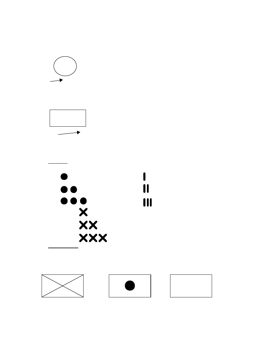
Marine Air Traffic Control Mobile Team
TACSOP
Optional Fields:
C Quantity of
E Unconfirmed Reporting
(indicated by “?”)
W
G
G Additional Information
H J K INSTALLATIONS
H Free Text
T
P
J Evaluation Rating
Q
K Combat Effectiveness
L Electronic Signature
Equipment (indicated by “!”)
C
E
M Higher Headquarters
W
G
Q Direction of Movement
Arrow
V
H J L EQUIPMENT
R Mobility Indicator
T
M N P
S Headquarters
Representation (ex. FWD)
R
V Type of Equipment
Q
W Date Time Group
III.
Unit Size. The size of the units and installations is shown by placing the appropriate size
indicator directly above the basic symbol (Field “B”).
Squad
Company / Battery
Section
Battalion
Platoon
Regiment
Brigade
Division
Corps / MEF
IV.
Role Indicator. The type or function symbols are placed inside the basic symbol (Field
A). Symbols can be combined with one another to show an exact function or capability of the
depicted unit. When no functional symbol I provided, an accepted abbreviation may be written
inside the basic symbol.
Infantry
Artillery
Electronic Warfare
K-17
EW
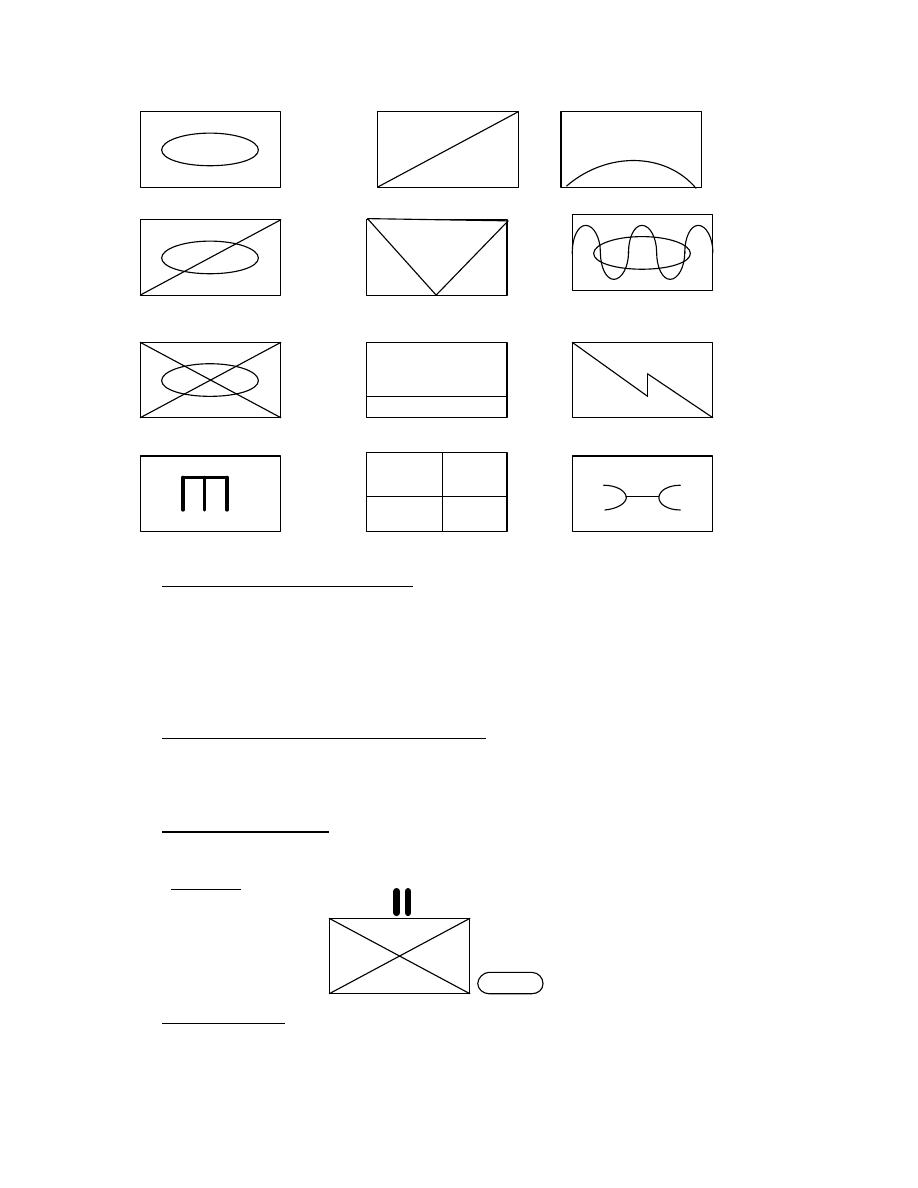
Marine Air Traffic Control Mobile Team
TACSOP
Armor
Reconnaissance
Air Defense
Light Armor
Anti Armor Assault Amphibious
Mech Infantry
Supply
Communications
Engineer
Medical
Maintenance
V.
Reinforcements and Detachments. If a unit is reinforced or has a detached element, this
is indicated to the right of the basic symbol in Field F.
Reinforced
(+) or (REIN)
Detached
(-)
With Detachments and
Reinforcements
(-)(+) or (-)(REIN)
VI.
Unique Designations and Higher Formations. The identity of the unit is located to the left
of the basic symbol in Field T . The unique designation must be consistent with the size
indicator. The identity of the higher headquarters is located to the right of the basic symbol in
Field M.
VII.
Special Size Indicators. A cap drawn in Field D over the size indicator designates a
temporary grouping or task force.
VIII.
Free Text. Field H contains additional information not indicated elsewhere. For
example:
(REIN)
Infantry Battalion
Reinforced with
Tanks
IX.
Mobility Indicator. The type of mobility is shown beneath the basic unit or equipment
symbol in Field R.
K-18
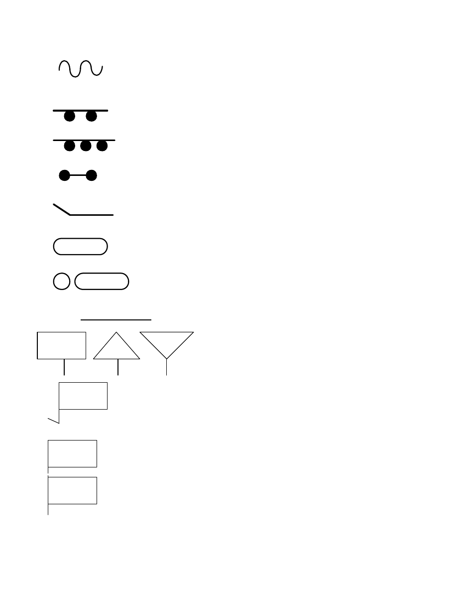
Marine Air Traffic Control Mobile Team
TACSOP
Amphibious
Wheeled
Wheeled Cross-Country
Trailer or Towed Vehicle
Oversnow
Tracked
Wheeled/Track Combination
X.
Precise Locations. The following methods are used to indicate precise locations:
Basic symbols, other than Headquarters,
may be placed on a staff which is extended or bent
as required. The end of the staff indicates the
precise location of the unit depicted.
Since the Headquarters symbol already has a staff,
the staff is then extended or bent. The end of the
staff indicates the precise location of the
Headquarters.
If a several headquarters are at one location, more
than one symbol may be placed on a single staff.
K-19
Marine Air Traffic Control Mobile Team
TACSOP
If a group of units or installations other than
headquarters is at one location, the grouping of
symbols may be enclosed in a bracket and the
exact location indicated by a line.
XI.
Examples.
2
2d Marines, Forward CP, on AAVs
FWD
Alfa Battery, 12
th
Marines, Observation Post
A
12
(-)(+) 1
st
Battalion, 7
th
Marines (minus) (reinforced) with Tanks,
1 7 Mechanized
K-20

Marine Air Traffic Control Mobile Team
TACSOP
APPENDIX L
EAF WEB SITES
Assault zone survey
https://www.amc.scott.af.mil/do/dosub.cfm?page=division%2Ehtm
Airfield Suitability and Restrictions Report
https://www.amc.af.mil/do/doa/dovs.htm
Terra Server (Imagery)
http://www.terraserver.com
Naval Facilities (P-80)
http://www.efdlant.navfac.navy.mil/www_20/P-80/ccn100.htm
DOT/FAA (Airport Markings, Signs, and Selected Surface Lighting)
http://www.asy.faa.gov/safety_products/smgcs.htm
Planning and Design of Roads, Airfields, and Heliports in the Theater of Operation
FM 5-430-00-1 Volume One – Road Design
FM 5-430-00-2 Volume Two – Airfield and Heliport Design
http://www.adtdl.army.mil/cgi-bin/atdl.dll/fm/5-430-00-1/toc.htm
http://www.adtdl.army.mil/cgi-bin/atdl.dll/fm/5-430-00-2/toc.htm
L-1

Marine Air Traffic Control Mobile Team
TACSOP
THIS PAGE INTENTIONALLY LEFT BLANK

Marine Air Traffic Control Mobile Team
TACSOP
APPENDIX M
AIRCRAFT DIMENSIONS
FIXED WING AIRCRAFT DIMENSIONS
AIRCRAFT TYPE:
HEIGHT:
LENGTH:
WIDTH:
A. WINGSPAN
B. WIDTH OVER MISSLES
C. WIDTH WINGS-STOWED
AV-8B HARRIER
11’6” (D)
13’2” (N)
46’3” (D)
47’10” (R)
50’3” (N)
A. 30’3”
B. NA
C. NA
F/A-18A/B/C/D
HORNET
15’3”
56.0’
A. 37’6”
B. 40’5”
C. 27’6”
F/A-18E/F SUPER
HORNET
60.1’
A. 41.8’
B. 44.7’
C. 30.6’
EA-6B PROWLER
16’8”
59’10”
A. 53’
B. NA
C. 25’10”
F-14A/D TOMCAT
16’
62’9”
A. 64’2”
B. NA
C. 38’3” (SWEPT)
KC-130 HERCULES
38’3”
99’6”
A. 135’7”
B. NA
C. NA
C-17
55’1”
173’11”
A. 169’9”
B. NA
C. NA
C-141B
14’7”
168’4”
A. 160’0”
B. NA
C. NA
C-5
65’1”
247’10”
A. 222’9”
B. NA
C. NA
M-1

Marine Air Traffic Control Mobile Team
TACSOP
APPENDIX M
AIRCRAFT DIMENSIONS
ROTARY WING AIRCRAFT DIMENSIONS
AIRCRAFT TYPE:
HEIGHT:
LENGTH WITH
ROTORS:
A. TURNING
B. STOWED
WIDTH WITH
ROTORS:
A. OPERATING
B. STOWED
C. & TAIL STOWED
AH-1W SUPER COBRA
13’9”
A. 58’
B. 58’
A. 48’
B. 10’9”
C. NA
UH-1N HUEY
13’1”
A. 57’4”
B. 57’4”
A. 48’
B. 9’5”
C. NA
CH-46 SEA KNIGHT
16’8”
A. 84’4”
B. 45’8”
A. 51’
B. 14’9”
C. NA
CH-53A/D SEA
STALLION
24’11”
A. 88’3”
B. 56’9”
A. 72’3”
B. 12’3”
C. 23’11” w/aux tanks
CH-53E SUPPER
STALLION
28’6”
A. 99’1”
B. 60’6”
A. 79’
B. 23’11”
C. 28’5” w/aux tanks
MV-22 OSPREY
22’1”
A. 57.3
B. 63.0
(BLADES FOLDED)
A. 84.5
B. 18.2 (WING &
BLADES FOLDED)
C. NA
M-2

Marine Air Traffic Control Mobile Team
TACSOP
APPENDIX N
REFERENCE LIST
FAA 7110.65 Air Traffic Control Handbook
AFI 13-217 Assault Zone Procedures
MCO 3500.19 Aviation Training and Readiness Manual, Vol. 5
OPNAVINST 3722.16C United States Standard for Terminal
Instrument Procedures
NAVAIR 00-80T-114 Air Traffic Control Facilities Manual (NATOPS)
NAVAIR 00-80T-115 Expeditionary Air Field (EAF) (NATOPS)
NAVAIR 01-75GAA-1T KC-130 Tactical Manual
NAVAIR 01-1ASH-1T Assault Support Helicopter Tactical Manual
DB 1-83 AN/TPN-30A
MCWP 5-1 Marine Corps Planning Process
MCO 3500.27 Operational Risk Management
MCRP 3-25B Multi-service Brevity Codes
FM 5-430-00-1 Volume One Planning and Design of Roads,
Airfields, and Heliports in the
Theater of Operation
FM 5-430-00-2 Volume Two (Vol. 1 Road Design; Vol. 2 Airfield and Heliport Design)
MCWP 3-25.8 Marine Air traffic Control Detachment Handbook
MCRP 3-25A Multiservice Procedures for Joint Air Traffic Control
JSC-HDBK-98-091 Joint Spectrum Center Field Antenna Handbook
N-1

Marine Air Traffic Control Mobile Team
TACSOP
THIS PAGE INTENTIONALLY LEFT BLANK
Wyszukiwarka
Podobne podstrony:
us marines serious incident reports 1996
US Marine Corps Warfighting
us dcid security violations 2002
US Marine Corps Insider Threat Solicitaton
us marine corps multi service brevity codes mcrp 3 25b
us crimintsum 2002 8 30
us crimintsum 2002 4 26
The US Army and Marine Corps Counterinsuring field manual
us crimintsum 2002 8 16
2002 US Air Force MILITARY SUPPORT TO CIVIL AUTHORITIES 21p
Ustawa z 30 10 2002 r o ubezp społ z tyt wyp przy pracy i chor zawod
Us ugi internetu dla LTK i SRK
ecdl 2002
Transfer sk adki US
ei 03 2002 s 62
2002 09 42
2002 06 15 prawdopodobie stwo i statystykaid 21643
więcej podobnych podstron