
Initial Print Date:9/02
Revision Date:
Subject
Page
Advanced Safety Electronics (ASE) . . . . . . . . . . . . . . . . . . . . . . . . . . . .3
Purpose of the System . . . . . . . . . . . . . . . . . . . . . . . . . . . . . . . . . . . . . .4
Advanced Safety Electronics IPO . . . . . . . . . . . . . . . . . . . . . . . . . . . . .5
System Components . . . . . . . . . . . . . . . . . . . . . . . . . . . . . . . . . . . . . . . .6
byteflight . . . . . . . . . . . . . . . . . . . . . . . . . . . . . . . . . . . . . . . . . . . . . . . .6
Control Units . . . . . . . . . . . . . . . . . . . . . . . . . . . . . . . . . . . . . . . . . . . . .8
SIM . . . . . . . . . . . . . . . . . . . . . . . . . . . . . . . . . . . . . . . . . . . . . . . . . . . .8
Power Supply . . . . . . . . . . . . . . . . . . . . . . . . . . . . . . . . . . . . . . . . . . . .8
Bus Master Functions . . . . . . . . . . . . . . . . . . . . . . . . . . . . . . . . . . . . . .9
Gateway . . . . . . . . . . . . . . . . . . . . . . . . . . . . . . . . . . . . . . . . . . . . . . .10
Gateway from K Bus to byteflight . . . . . . . . . . . . . . . . . . . . . . . . . . . .10
Gateway from byteflight to the K-Bus . . . . . . . . . . . . . . . . . . . . . . . . .10
B-Pillar Satellites (SBSL and SBSR) . . . . . . . . . . . . . . . . . . . . . . . . . .11
Sensors . . . . . . . . . . . . . . . . . . . . . . . . . . . . . . . . . . . . . . . . . . . . . . .11
Door Satellites (STVL/STVR) . . . . . . . . . . . . . . . . . . . . . . . . . . . . . . . .11
Seat Occupancy Sensor . . . . . . . . . . . . . . . . . . . . . . . . . . . . . . . . . . .12
B+ Cable Monitoring . . . . . . . . . . . . . . . . . . . . . . . . . . . . . . . . . . . . . .12
Seat Belt Switches . . . . . . . . . . . . . . . . . . . . . . . . . . . . . . . . . . . . . . .13
Airbag Switch . . . . . . . . . . . . . . . . . . . . . . . . . . . . . . . . . . . . . . . . . . .13
Actuators . . . . . . . . . . . . . . . . . . . . . . . . . . . . . . . . . . . . . . . . . . . . . .14
Driver’s Airbag . . . . . . . . . . . . . . . . . . . . . . . . . . . . . . . . . . . . . . . . . .14
Passenger Airbag . . . . . . . . . . . . . . . . . . . . . . . . . . . . . . . . . . . . . . . .14
Side Airbags . . . . . . . . . . . . . . . . . . . . . . . . . . . . . . . . . . . . . . . . . . . .15
Knee Airbags . . . . . . . . . . . . . . . . . . . . . . . . . . . . . . . . . . . . . . . . . . .15
Seat Belt Tensioner . . . . . . . . . . . . . . . . . . . . . . . . . . . . . . . . . . . . . . .16
Battery Safety Terminal . . . . . . . . . . . . . . . . . . . . . . . . . . . . . . . . . . . .16
Airbag Indicator Lamp . . . . . . . . . . . . . . . . . . . . . . . . . . . . . . . . . . . .17
Table of Contents
Advanced Safety Electronics (ASE)

2
Advanced Safety Electronics
Principle of Operation . . . . . . . . . . . . . . . . . . . . . . . . . . . . . . . . . . . . . .17
Airbag Triggering . . . . . . . . . . . . . . . . . . . . . . . . . . . . . . . . . . . . . . . . .19
Triggering in the event of errors . . . . . . . . . . . . . . . . . . . . . . . . . . . . .19
Triggering in the event of a crash . . . . . . . . . . . . . . . . . . . . . . . . . . . .19
Front-end crash . . . . . . . . . . . . . . . . . . . . . . . . . . . . . . . . . . . . . . . . .19
Side-on collision . . . . . . . . . . . . . . . . . . . . . . . . . . . . . . . . . . . . . . . . .20
Rear crash . . . . . . . . . . . . . . . . . . . . . . . . . . . . . . . . . . . . . . . . . . . . .20
Knee Airbag . . . . . . . . . . . . . . . . . . . . . . . . . . . . . . . . . . . . . . . . . . . .20
Battery Cable Monitoring . . . . . . . . . . . . . . . . . . . . . . . . . . . . . . . . . .21
Review Questions . . . . . . . . . . . . . . . . . . . . . . . . . . . . . . . . . . . . . . . . .23

3
Advanced Safety Electronics
Advanced Safety Electronics (ASE)
Model: E85
Production: Start of Production MY 2003
Objectives:
After completion of this module you should be able to:
•
Relate the ASE component locations.
•
Understand the operation of the ASE System.
•
Explain the operation of the Battery Cable Monitioring System.

4
Advanced Safety Electronics
Purpose of the System
Advance Safety Electronics
Advanced Safety Electronics ASE is the passive safety system on the E85. The system is
based on the same technology as the Intelligent Safety and Integration System (ISIS) of the
E65/E66.
The ASE system consists of the Safety Information Module SIM and several control units,
called satellites, that are linked across the byteflight bus. In the case of the MRS system
there was only one central control unit. On the E85, the acceleration sensors are integrat-
ed into the satellites.
The actuators are directly connected to the satellites and are activated by the satellites. The
satellites are fitted at strategic points in the car. The distributed sensor system in the car
enables measurement of the accelerations occurring as close as possible to the outer shell
of the body and at the location of the collision.
The direct recording and processing of the information in the control unit mean that signif-
icantly shorter reaction times can be achieved. The mechanical time lag within the body to
a central control unit is eliminated.
The distributed sensors in the satellites provide redundant information that is interchanged
via the byteflight. This leads to even more reliable trigger decisions. In comparison to the
MRS systems used to date, the ASE enables, (for example in the event of a side-on colli-
sion) earlier triggering.
Advantages of the ASE System
•
Networked airbag control system with optical bus byteflight
•
More exact crash detection regarding the direction and strength ofthe impact
•
Battery cable diagnosis with cutoff of the safety battery terminal when required
•
Airbag switch for deactivation/activation of the front airbags on passenger side, side
airbags and knee airbag on US models
•
Deployment of a knee airbag for driver and passenger on US model
The crash situation is detected more precisely than on the multiple restraint system MRS.
In the event of a crash, only those actuators are triggered that are necessary for optimum
protection of the driver and passenger. This leads to lower repair costs and thus more
favourable insurance classifications.
A number of acceleration sensors in the vehicle record the vehicle deceleration. The satel-
lites exchange acceleration data. This provides an exact picture of the crash situation,
enabling a timely and selective triggering of the actuators depending on the crash situation.

5
Advanced Safety Electronics
Advanced Safety Electronics IPO
1. Instrument Cluster
11. Right Side Airbag
21. Transverse Sensor in SIM
2. DME Control Unit
12. Right Knee Airbag
22. Longitudinal Sensor in SIM
3. GM V
13. Right Seat Belt Tensioner
23. Airbag Switch
4. Fuel Pump Relay
14. BST
24. SIM
5. Driver’s Side Front Airbag
15. SBSR
25. Under Hood Battery Connection
6. Left Side Airbag
16. Seat occupancy sensor
26. Transverse sensor in SBSL
7. Left Knee Airbag
17. Right seat belt switch
27. Longitudinal Sensor in SBSL
8. Left Seatbelt Tensioner
18. Transverse sensor in SBSR
28. Left Seatbelt Switch
9. Airbag Indicator Lamp
19. Longitudinal sensor in SBSR
29. Telephone Emergency Call
10.Passenger Side Front Airbag
20. Trunk Battery Connection
30. SBSL

6
Advanced Safety Electronics
System Components
The ASE system consists of the following components:
•
byteflight bus
•
Control Units
SIM - With acceleration sensors
SBSL - satellite b-pillar on left side of vehicle
SBSR - satellite b-pillar on right side of vehicle
•
Sensors
STVL - pressure sensor left door
STVR - pressure sensor right door
Seat occupancy sensor
B+ Cable Monitoring
Seat Belt Switches -Driver and Passenger
Airbag Switch
•
Actuators
Driver’s Side Airbag (2 stage)
Passenger Side Airbag (2 stage)
Side Airbags (2)
Knee Airbag Driver’s Side
Knee Airbag Passenger Side
Seat Belt Tensionsers (2)
BST
Airbag Indicator Light
byteflight
The increasing complexity of in-car electronics and the growing amount of sensors, actua-
tors and electronic control units place higher demands on the high-speed data communci-
ation protocols.
None of the communication solutions available until now have been able to fulfill all these
demands.
BMW together with several semi-conductor companies have developed byteflight a new
protocol for safety-critical applications in automotive vehicles.
The byteflight is the bus system used exclusively for the ASE System (Intelligent Safety
Integration System). This ASE Sytem of the E85 contains the Safety and Information
Module (SIM) and 4 additional satellite control modules.
The ASE System is a bus composed of Fiber Optic cables and control modules arranged
in a STAR pattern with the SIM at the center of the system.

7
Advanced Safety Electronics
Since the byteflight is a star structure as opposed to the continious ring structure of the
MOST bus, the fiber optic cables carry the data bi-directionally, a single fiber optic cable
connects each satellite directly to the SIM.
Each satellite contains a transmitter/receiver module for receiving and sending data to the
SIM. The SIM contains 4 transmitter receiver modules for communication with the satellites
simultaneously.
All information from each satellite is made available to every other satellite by the SIM.
Note:
Repairs to the byteflight fiber-optic cable are not permitted. Damaged cables must be
replaced with new fiber optic cables.
Because of the use of byteflight, the ASE system has the following advantages:
•
High communication speed
•
Highest level of system security
•
Faster trigger decisions
•
Redundant information provided by the sensor
•
Software update via bus
•
Self-diagnostic procedure
•
Mechanical safety switch is unnecessary
•
No electromagnetic disturbances due to fiber-optic communication
•
No electrical connection between transmitter and receiver module
•
Simple system upgrade
ASE byteflight Bus System

8
Advanced Safety Electronics
Control Units
SIM
Located on the transmission tunnel behind the
handbrake assembly, the Safety and Information
Module (SIM) performs the following functions:
•
Supplies voltage to the satellites and the pressure sensors (SBSL,SBSR and
STVL,STVR) and supplies the voltage reserve for component activation.
•
Bus Master functions for the optical bus communication system (byteflight).
•
Gateway functions between byteflight and K-bus.
•
Triggers Emergency Call System (If Phone equipped)
•
Signals the DME for deactivation of fuel pump.
•
Signals the GM to switch on interior lights, hazard warnings and unlock the doors.
•
Monitors the integrated acceleration sensors.
•
Allows airbag activation.
•
Allows BST activation.
Power Supply
The SIM is supplied with voltage KL terminals 30 and ground from KL31. If the vehicle volt-
age is sufficient then a switching controller is supplied first, which supplies voltage to the
intelligent Star Coupler and the power supply.
The second switching controller is supplied by KL 30 during operation and is controlled by
the microprocessor via the cable SHDN 2. The capacitor is charged as of KL R.
The charging of the capacitor forms the emergency energy reserve. The capacitor voltage
is 33V. (Energy Reserve in the E65 is 400v.)
SIM Location
1. Instrument Cluster
2. DME
3. Mayday Function (Not available at this time)
4. GM V
5. Switching Controller
6. Voltage Regulator
7. Microprocessor
8. Airbag Switch
9. Airbag Indicator Lamp
10. Longitudinal Acceleration Sensor
11. Transverse Acceleration Sensor
12. Star Coupler
13. Distributor
14. Energy Reserve Capacitor
15. Right B-Pillar Satellite
16. Left B-Pillar Satellite
17. Battery
18. Ignition/Starter Switch
9
Advanced Safety Electronics
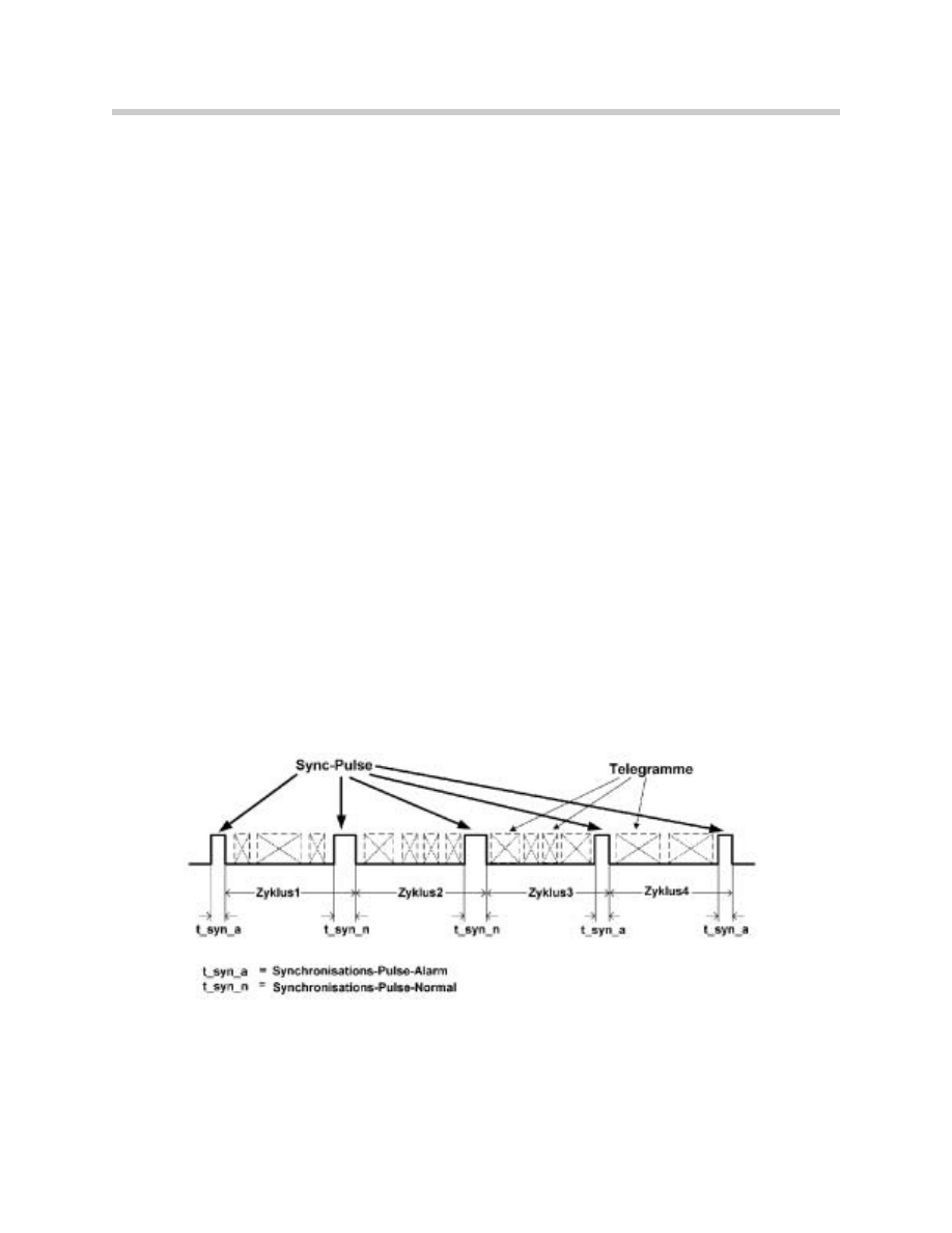
Bus Master Functions
The SIM has two tasks to perform as Bus Master for the byteflight.
•
Generation of the synchronization pulses (Sync. Pulse)
•
Setting the satellites in alarm mode (Alarm Pulse)
In the ASE, the SIM is configured as byteflight master (bus master). In principle, any satel-
lite can be configured by software as bus master. However, there may only be one bus
master in the system.
All other satellites (bus slaves) use the sync pulse for internal synchronization. Each slave
can transmit telegrams between the sync. pulses on the byteflight.
The SIM provides the synchronization pulses at intervals of 250
µs. The alarm mode is
transmitted across the width of the sync. pulse. The duration of a sync. pulse in alarm sta-
tus is approx. 2
µs. Normally, the synchronization pulse lasts approx. 3µs.
The duration of a complete telegram can vary between 4.6 to 16
µs.
On the basis of all the available information provided by the sensors, the bus master (SIM)
must decide whether the satellites are to be set in the alarm mode.
When the alarm mode is set by the SIM, all the trigger circuits (B+) of the ASE are placed
on trigger standby.

10
Advanced Safety Electronics
Gateway
The SIM contains the gateway function between the byteflight and K-bus. This means that
telegrams can be sent by the byteflight to the K-bus and vice versa.
The gateway function transfers both the content of functional telegrams as well as the
telegrams for diagnosis.
Gateway from K Bus to byteflight
Information and messages for the ASE system are forwarded by the K-bus as telegrams to
the byteflight (gateway function of the SIM). The telegrams are processed in the SIM.
The following telegrams are transmitted:
•
Terminal status
•
Kilometre reading
•
Vehicle identification number
Gateway from byteflight to the K-Bus
The messages and information from the byteflight that are meant for other nodes on the K-
bus are converted by the gateway function into a K-bus telegram. The following signals
are transmitted in a telegram (crash telegram):
•
Switch on airbag warning lamp, AWL
•
Switch off electric fuel pump
•
Switch off alternator
•
Transmit emergency call
•
Open central locking system
•
Switch on passenger-compartment lighting and hazard warning light
Notes:

11
Advanced Safety Electronics
B-Pillar Satellites (SBSL and SBSR)
The left side B-Pillar Satellite (SBSL) controls and monitors the actuators for the left front
airbag, the left side airbag ( in the drivers door), the left seat belt tensioner and the left knee
airbag.
The right side B-Pillar Satellite (SBSR) controls and monitors the actuators for the right front
airbag, the right side airbag (in the passenger door), the right seat belt tensioner, the right
knee airbag and the BST.
Both B-Pillar Satelittes function as monitors for the BST.
The B-Pillar satellites are connected to the SIM via the byteflight. The power supply of the
satellites is also from the SIM and it is buffered by the memory backup capicitor.
An accleration sensor for the longitudinal and transversal acceleration is integrated in each
B-Pillar satellite. The sensor provides voltage as a measured variable and transfers the value
via the byteflight to the SIM and all other satellites.
The voltage signal is a measurement of positive and negative car acceleration and is eval-
uated in each satellite. The voltage signal is continuoulsy provided to the SIM and other
satellites.
Sensors
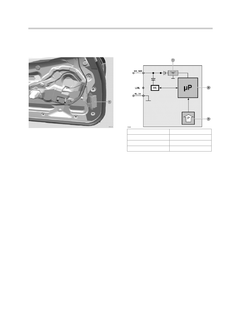
Door Satellites (STVL/STVR)
The Door Satellites (STVL/STVR) are located in the left/right passenger doors.
The door satellites are connected to the SIM via the byteflight. Power supply for the door
satellites is also provided by the SIM and is buffered by the memory backup capcitor.
SBSL Location
SBSR Location
12
Advanced Safety Electronics
A pressure sensor, which constanlty monitors the pressure in the door, is integrated into
each door satellite. Pressure changes in the door that occur during penetration of the outer
door skin are evaluated and passed on through the SIM for airbag deployment activation.
Seat Occupancy Sensor
A seat occupancy detection mat is installed in the seat cushion of the passenger seat.
The sensor mat is identical to the mats used in previous models for the MRS systems. The
sensor system consists of pressure sensors that use an electronic evaluation unit (SBE) to
detect whether there is weight on the seat.
When a weight (such as a passenger) is added to the seat, the system recognizes the seat
as occupied. The electronic evaluation unit of the seat occupation mat is connected to the
SBSR satellite.
The information regarding seat occupation is required for activation of the following
functions:
•
Airbag activation
•
Activation of the seatbelt tensioners
B+ Cable Monitoring
The E85 B+ Battery Cable is routed from trunk area along the underside of the car into the
engine compartment. If the cable is damaged in an accident or while driving over an obsta-
cle, the BST is activated, protecting the vehilce from further electrical problems.
1. Voltage Regulator
VS_SIM Voltage Supply
2. Microprocessor
KL31 Terminal 31
3. Pressure Sensor
LWL byteflight
S/E Transmitter/Receiver

13
Advanced Safety Electronics
The battery cable monitoring occurs via the low impedence shield of the battery cable, the
monitoring shield. The monitoring point in the trunk at the BST is connected to the SBSR
and the other monitoring connection in the engine compartment is connected to the SBSL.
Seat Belt Switches
The Seat Belt Switches are located in the seatbelt buckles of the driver and passenger seat
belt. The switch is a two wire hall switch and is supplied with voltage by the respective left
and right B-Pillar satellites (SBSL/SBSR). The voltage is pulsed to the switch to reduce volt-
age consumption.
The seat belt switches are used to detect whether or not the seat belts have been fastened.
The input from the switches is required for the following functions:
•
Selective triggering of actuators in the event of a crash
•
Activation of the Seat Belt Warning Lamp
•
Out of the accoustic warning
Airbag Switch
B+ Monitored Battery Cable
1. Outer insulation
2. Monitoring Shield
3. Insulation of aluminum cable
4. Aluminum cable 35mm2
14
Advanced Safety Electronics
The airbag switch is located on the right side of the dashboard at the A-Pillar and the indi-
cator lamp for is located in the center console.
The airbag switch makes its possible for the driver to determine if the passenger front and
side bags are active. The front passenger and passenger side airbag are activated or deac-
tivated together only.
To prevent accidental activation or deactivation of the passenger airbags the switch may
only be operated by the ignition key while the car is not moving and the passenger door is
open.
The airbag indicator lamp consists of a number of LED’s controlled by the SIM.
Actuators
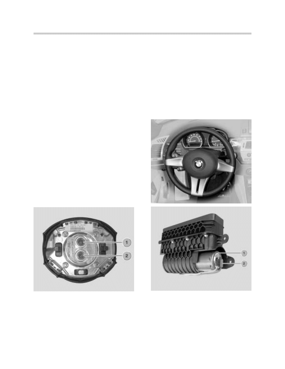
Driver’s Airbag
The Driver’s Airbag is located in the impact pad
of the three spoke steering wheel.
The Bag is equipped with a 2-stage gas gen-
erator and has a volume of approxiamately 60
liters.
Three colors are availbable to match the interi-
or colors. (Black, Brown, Grey)
Passenger Airbag
The Passenger Airbag is located beneath an invisible flap in the dashboard. The airbag is
a 2-stage design with a volume of approximately 125 liters. Depending on the severity of
the crash, the two stages are ignited so the the bag can unfold in a defined manner.
1. Stage 1
2. Stage 2
15
Advanced Safety Electronics
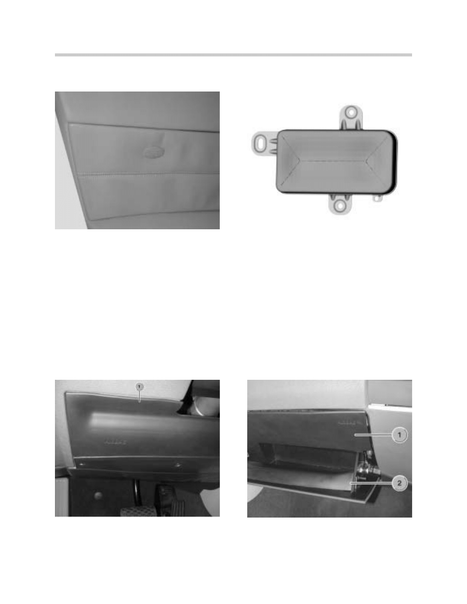
Side Airbags
The side airbags in the doors reduce the risk of occupant injury in the torso region of the
body in the case of a side-on crash.
The side airbags are located behind the door trim. The side airbags are secured to the inner
door panel with 3 screws.
The side airbags are folded up in an aluminium housing with a plastic cover. The plastic
cover has defined breaking points.
Knee Airbags
E85 Side Airbag in door
E85 Side Airbag Module
Drivers Knee Airbag
1. Dirvers Side Knee Airbag
Passenger Knee Airbag
1. Passenger Knee Airbag
2. Glove Compartment
16
Advanced Safety Electronics
In the event of a crash, the knee airbag supports the knee, especially if the driver or pas-
senger are not wearing seatbelts. This initiates a controlled forward shift of the upper body,
which is cushioned by the relevant airbag.
The knee airbag is a one-stage airbag with gas generator. The volume is approx.13 litres.
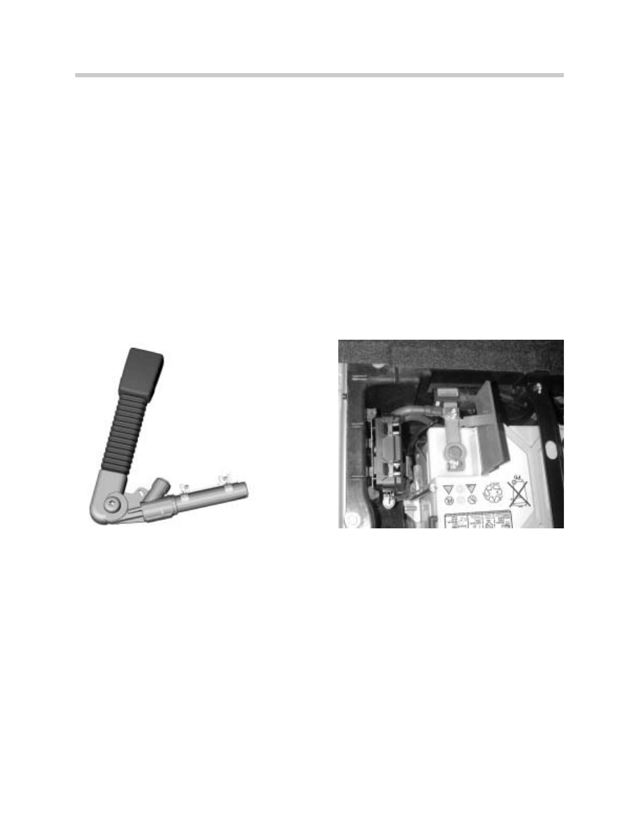
Seat Belt Tensioner
The pyrotechnic seatbelt tensioner has the task in the event of a crash to remove or reduce
any belt slack in the pelvic and shoulder region.
The seatbelt tensioner is located on the driver's and/or passenger seat. The seat belt ten-
sioners form a unit with the seat belt buckle.
The seatbelt tensioner consists of priming cap, generator, plunger and operating cable. The
belt buckle switch is integrated in the seatbelt buckle.
Battery Safety Terminal
In the event of a crash of sufficient severity or if the battery cable diagnosis is activated, the
starter/alternator line is electrically and mechanically cut from the positive terminal of the
battery.
The safety battery terminal is located directly at the positive terminal of the battery.
Seat Belt Tensioner
Battery Safety Terminal

17
Advanced Safety Electronics
Airbag Indicator Lamp
The airbag indicator lamp is activated when the
airbag switch assigns the state "Passenger
Airbag OFF."
The airbag indicator lamp is activated by the
SIM.
The airbag indicator lamp is diagnosed and
monitored. If a fault is found in the power sup-
ply or at the lamp, a fault entry is made in the
SIM.
The airbag warning lamp is activated.
Principle of Operation
The SIM now has 4 transmit/receive modules to which the satellites are connected.
The energy reserve in the SIM has been reduced to 33 V (ASE 400 V), as now only 4 satel-
lites have to be supplied with voltage in the event of a crash.
New additions are the acceleration sensors for the X/Y direction.
The acceleration sensors for the X/Y direction measure the longitudinal and transversal
acceleration of the vehicle and are evaluated in the SIM. The sensors continuously provide
the values determined. The values are transferred across the byteflight to all satellites, as
are the measured values of the satellites. The algorithms in the satellites work with these
measured values. The SIM compares the values and triggers the alarm mode via synchro-
nization pulses if the severity is sufficient.
The alarm mode places the satellites in a triggerable state. Depending on the crash sever-
ity and the stored trigger algorithms, the actuators required in each case are activated.
Note:
If an airbag switch is fitted and the switch is in the position "deactivated," the front airbag
on the passenger side and the side airbag are not placed in the triggerable state. The knee
airbag and the seat belt tensioner are also not place in the triggerable state.
The vehicle centre satellite has been eliminated, as the SIM is fitted in the middle of car and
the acceleration sensors are integrated in the SIM.

18
Advanced Safety Electronics
1. Instrument cluster
11. Transverse Acceleration sensor
2. DME Control Unit
12. Star Coupler
3. Telephone Emergency Call (Not Available at SOP)
13. Distributor
4. General Module GM V
14. Energy Reserve
5. Switching controller
15. Right B-Pillar Satellite
6. Voltage Regulator
16. Left B-Pillar Satellite
7. Microprocessor
17. Right Door Satellite
8. Airbag Switch
18. Left Door Satellite
9. Airbag Indicator Lamp
19. Battery
10. Longitudinal acceleration sensor
20. Ingition/Starter Switch

19
Advanced Safety Electronics
Airbag Triggering
Numerous crash and road tests under extreme conditions have been used to set the BMW
triggering thresholds for all possible types of accidents.
The triggering thresholds are primarily divided into 4 groups according to crash severity:
•
CS 0: no crash (parking damage)
CS=Crash Severity
•
CS 1: light crash
•
CS 2: crash of medium severity
•
CS 3: severe crash
The triggering thresholds have been set depending on the crash severity and including
other factors such as direction, overlap on collision, and depending on the evaluation as to
whether the occupant was wearing a seatbelt or not.
This results in the various trigger thresholds for the activation of the various restraint sys-
tems.
Triggering in the event of errors
If a fault is detected in the seatbelt buckle detection system, it is assumed that the seatbelt
is not fastened. The triggering threshold is lowered. In spite of the fault recognition, an
attempt is made to activate the seatbelt lock tensioner.
If a fault is detected in the seat occupation detection system, it is assumed that the seat is
occupied. The restraint systems are activated.
If a fault is detected in the airbag switch, it is assumed that a child's seat is fitted. The front
airbag and side airbag on the passenger side are not triggered.
Triggering in the event of a crash
The following examples illustrate the actuators that can be activated:
•
Front-end crash
•
Side-on collision
•
Rear crash
Front-end crash
In the event of a front-end crash, a distinction is made between crash severity "light to
medium collision" or "severe collision" (CS 3).
In the case of crash severity from light to medium collision (CS 1/CS 2), the driver's/front
passenger's airbag are not triggered if it is detected that the occupants are wearing seat-
belts.

20
Advanced Safety Electronics
If the occupants are not wearing seatbelts, the driver's and front passenger's airbag would
be triggered.
The seatbelt tensioners are triggered in all cases.
As of crash severity CS 2, the driver's/front passenger's airbag as well as the seatbelt ten-
sioners are triggered. The safety battery terminal is activated, the electric fuel pump is
switched off, and an emergency call is placed if a correspondingly prepared telephone is
present in the vehicle.
In the US version, the knee airbags are also triggered.
Side-on collision
In the event of a side-on collision, a crash severity distinction is made between medium and
severe collisions.
As of crash severity of CS 2 (medium collision), the side airbag is triggered on the impact
side. In the event of crash severity CS 3 (severe collision), the safety battery terminal is also
activated, the electric fuel pump is switched off, and an emergency call is placed if a cor-
respondingly prepared telephone is present in the vehicle.
Rear crash
As of crash severity CS 2 (medium collision), the seatbelt tensioners are triggered.
In the event of crash severity CS 3 (severe collision), the safety battery terminal is also trig-
gered, the electric fuel pump is switched off, and an emergency call is placed if a corre-
spondingly prepared telephone is present in the vehicle.
Knee Airbag
In the event of a crash of sufficient severity, the gas generator is ignited. The escaping gas
fills the airbag, which tears open the cover of the knee airbag so that the airbag can
emerge.
The airbag spreads out beneath the steering column and/or in front of the glove compart-
ment and cushions the lower thighs of the occupant.
The support of the lower thighs initiates a controlled forward shift of the upper body, which
is cushioned by the driver or passenger airbag.
The knee airbags can only be seen by the lettering "AIRBAG" on the cover of the airbag
module as well as on the cable connection for the airbag module.

21
Advanced Safety Electronics
Battery Cable Monitoring
The battery cable is diagnosed by a special circuit between the SBSL and SBSR satellites.
The battery cable diagnosis takes place across the low impedance shield of the battery
cable (monitoring shield). The monitoring shield monitors the state of the battery cable
as follows:
There are connections to the left B-pillar satellite and the right B-pillar satellite at both ends
of the shield. This means that there is usually the same voltage at the
analog/digital converters in the satellites. If the voltages differ, there is a fault.
The monitoring shield consists of a low-impedance metal mesh. A connection cable exits
from each end of the monitoring shield (at the safety battery terminal in the luggage com-
partment and at the battery earth point in the engine compartment).
The connection at the safety battery terminal in the luggage compartment is connected to
the right B-pillar satellite. The second connection cable in the engine compartment is con-
nected to the left B-pillar satellite.
The satellites contain analog/digital converters that are connected to the microprocessor of
the satellite. The connection cables of the battery cable diagnosis are connected to the A/D
converters.
The right B-pillar satellite contains a pull-up resistor.
The left B-pillar satellite contains a pull-down resistor of the same size.
The voltage supply of the satellite (approx. 10 V) is applied at the pull-up resistor. Ground
is applied at the pull-down resistor.
The very low-impedance cable and the resistors of the same size mean that around half the
voltage (approx. 5 V) is applied at the A/D converters.
Block Diagram Battery Cable Monitoring
G Generator
M Starter
1. Battery Cable
2. Monitoring Shield
3. Battery Safety Terminal BST
4. Battery
SBSL Left B-Pillar Satellite
SBSR Right B-Pillar Satellite
up Microprocessor

22
Advanced Safety Electronics
Every 250 µs, the values are measured, triggered by the synchronization pulse. If the bat-
tery cable is OK, the values are transferred every 20 ms to the SIM. If a significant deviation
of the values occurs, the new values are transferred immediately.
In the following cases, the battery cable is cut off by the safety battery terminal from the
battery and the alternator is switched off:
•
Short circuit to ground (body)
•
Short to battery positive
If the outer insulation is damaged (e.g. due to friction/scuffing), but the monitoring shield
has no connection toground, the following case could occur:
Moisture (rain) would mean that the voltage would gradually fall. A short circuit to ground
would be detected, but the safety battery terminal would not be triggered.
The entry "Implausible measured value" is set in the fault code memory. This would be indi-
cated to the driver by the airbag warning lamp.
Service Notes
The following must be observed by Service:
•
Battery cable diagnosis
•
Safety battery terminal
•
Airbag warning lamp
Battery cable diagnosis
If the shielding of the battery cable is damaged, the battery cable must be replaced com-
pletely. It is not permitted to repair the shielding.
Safety battery terminal
If the safety battery terminal is activated, the battery cable must be replaced completely.
Repair is not intended.
Airbag warning lamp
If there is a fault and the airbag warning lamp is switched on, the mileage is also docu-
mented in the fault code memory in the instrument cluster.
A mileage reading that has been entered can not be overwritten. For this reason, in the case
of an airbag fault, the fault code memory in the instrument cluster must also be
checked and deleted.
State
Measured Value
SBSL
Measured Value
SBSR
Battery Cable OK
5V
5V
Interuption of the diagnostic connection
0V
10V
Short circuit to ground
0V
0V
Short to B+
12v
12v

23
Advanced Safety Electronics
Review Questions
1. The byteflight system is a arranged as a structure.
2. What advantages does the byteflight fiber optic system offer over a copper wired bus
system.
3. What functions does the SIM perform ?
4. What is the purpose of the STVL/STVR Satellites?
5. What conditions must be met for the airbag switch to activate or deactivate the airbags?
6. Which airbags are activated/deactivated by the airbag switch?
7. What component supplies the voltage to the battery monitoring cable in the trunk?
8. Damage to ONLY the outer insulation of the monitored battery cable would result in
what action being taken at the BST?
9. When must the monitored battery cable be replaced?
10. How is the ASE warning light in the Instrument cluster turned off?
Document Outline
- Main Menu
- E85 Complete Vehicle
- E85 BodyShell
- M54 Engine
- MS45 DME Part 1
- MS45 DME Part 2
- MS45 DME Part 3
- MS45 DME Part 4
- E85 Driveline
- E85 Chassis Dynamics
- E85 Heating & Air Cond
- E85 Power Supply
- E85 Adv.Safety Elec.
- E85 Driver Information
- E85 Central Body Elec.
- E85 Communications
- E85 Updates
Wyszukiwarka
Podobne podstrony:
09 E60 Advanced Safety Electronics
PBO G 09 F07 Quality & safety system audit checklist in?pa
09 F01 Passive Safety Systems
09 E70 Passive Safety Systems
09 E70 Passive Safety WB
Instrukca obsl ELECTRA(Piłat-korekta 26 09), Instrukcje w wersji elektronicznej
Electrical Safety Student Manual
Everyday Practical Electronics 2001 09
electraplan cennik 10 10 09
ELECTRICAL SAFETY
09 Electrical equipment
Expoliner Safety 2011 06 09
electraplan cennik 10 10 09
Elektor Electronics 2007 09
Instrukca obsl ELECTRA(Piłat-korekta 26 09), Instrukcje w wersji elektronicznej
09 Electrical Part List
building regulations electrical safety jan 2005 bezpieczna elektryka
Safety Handbook [B 80687EN 09]
więcej podobnych podstron