
P
The Building Regulations 2000
Electrical safety
APPROVED DOCUMENT
P1
Design, installation, inspection and testing
P2
Provision of information
Building Regulations 2000
APPROVED
DOCUMENT
P
Electrical Safety
Coming into effect 1 January 2005
© Crown Copyright 2004.
Copyright in the typographical arrangement and design rests with the Crown.
Published for the Office of the Deputy Prime Minister, under licence from the Controller of Her Majesty’s Stationery Office.
This publication, excluding logos, may be reproduced free of charge in any format or medium for research, private study or for internal circulation
within an organisation.This is subject to it being reproduced accurately and not used in a misleading context.The material must be acknowledged
as Crown copyright and the title of the publication specified.
For any other use of this material please write to The HMSO Licensing Division, HMSO, St Clements House, 2–16 Colegate, Norwich NR3 1BQ.
Fax: 01603 723000 or email: licensing@cabinet-office.x.gsi.gov.uk
£15
www.tso.co.uk
Published by TSO (The Stationery Office) and available from:
Online
www.tso.co.uk/bookshop
Mail,Telephone, Fax & E-mail
TSO
PO Box 29, Norwich NR3 1GN
Telephone orders/General enquiries: 0870 600 5522
Fax orders: 0870 600 5533
E-mail: book.orders@tso.co.uk
Textphone: 0870 240 3701
TSO Shops
123 Kingsway, London WC2B 6PQ
020 7242 6393 Fax 020 7242 6394
68–69 Bull Street, Birmingham B4 6AD
0121 236 9696 Fax 0121 236 9699
9–21 Princess Street, Manchester M60 8AS
0161 834 7201 Fax 0161 833 0634
16 Arthur Street, Belfast BT1 4GD
028 9023 8451 Fax 028 9023 5401
18–19, High Street, Cardiff CF10 1PT
029 2039 5548 Fax 029 2038 4347
71 Lothian Road, Edinburgh EH3 9AZ
0870 606 5566 Fax 0870 606 5588
TSO Accredited Agents
(see Yellow Pages)
and through good booksellers
Part P build regs Cover jan 2k5 5/1/05 14:20pm Page 1

The following documents have been approved
and issued by the Secretary of State for the
purpose of providing practical guidance with
respect to the requirements of the Building
Regulations 2000 (as amended)
Approved Document A - Structure: 1992
Edition, fourth impression (with amendments)
1994, further amended 2000
Approved Document B - Fire safety:
2000 Edition, amended 2000 and 2002
Approved Document C - Site preparation and
resistance to moisture: 1992 Edition, second
impression (with amendments) 1992, further
amended 2000
Approved Document D - Toxic substances:
1985 Edition, amended 1992, further amended
2000
Approved Document E - Resistance to the
passage of sound: 2003 Edition
Approved Document F - Ventilation:
1995 Edition, amended 2000
Approved Document G - Hygiene:
1992 Edition, second impression (with
amendments) 1992, further amended 2000
Approved Document H - Drainage and waste
disposal: 2002 Edition
Approved Document J - Combustion
appliances and fuel storage systems:
2002 Edition
Approved Document K - Protection from
falling, collision and impact: 1998 Edition,
amended 2000
Approved Document L1 - Conservation of
fuel and power in dwellings: 2002 Edition
Approved Document L2 - Conservation of
fuel and power in buildings other than
dwellings: 2002 Edition
Approved Document M - Access and
facilities for disabled people: 2004 Edition
Approved Document N - Glazing - safety in
relation to impact, opening and cleaning:
1998 Edition, amended 2000
Approved Document P - Electrical safety:
2004 Edition
Approved Document to support regulation
7 - materials and workmanship: 1999 Edition,
amended 2000
Electrical safety
Approved Document P
Printed in the United Kingdom for The Stationery Office
169827 C200 07/04
Approved Document P
Electrical safety
P
APPROVED DOCUMENTS
Approved Documents
Part P build regs Cover jan 2k5 5/1/05 14:20pm Page 3

PAGE
USE OF GUIDANCE
3
THE REQUIREMENTS
5
SECTION 0: GENERAL GUIDANCE
7
Performance
7
General
7
Definitions
7
Other regulations
7
Notification of work
7
SECTION 1: DESIGN, INSTALLATION, INSPECTION AND TESTING
10
General
10
Accessibility
10
Inspection and testing before taking into service
10
Model certificates
11
SECTION 2: EXTENSIONS, MATERIAL ALTERATIONS AND MATERIAL CHANGES OF USE
12
SECTION 3: INFORMATION ABOUT OTHER LEGISLATION
13
Electricity at Work Regulations 1989
13
Electricity Safety, Quality and Continuity Regulations 2002
13
Functionality requirements
13
APPENDIX A: EXAMPLES OF ELECTRICAL INSTALLATION DIAGRAMS
14
APPENDIX B: COPIES OF BS AND IEE MODEL FORMS
19
APPENDIX C: OLDER PRACTICE THAT CAN BE ENCOUNTERED IN ALTERATION WORK
34
APPENDIX D: NEW HARMONISED CABLE IDENTIFICATION COLOURS
39
STANDARDS REFERRED TO
40
OTHER PUBLICATIONS REFERRED TO
40
Contents
Electrical safety
Approved Document P
1
P
ELECTRICAL SAFETY

Approved Document P
Electrical safety
2
P
ELECTRICAL SAFETY

THE APPROVED DOCUMENTS
This document is one of a series that has been
approved and issued by the Secretary of State
for the purpose of providing practical guidance
with respect to the requirements of Schedule 1
to and regulation 7 of the Building Regulations
2000 (SI 2000/2531) for England and Wales. SI
2000/2531 has been amended by the Building
(Amendment) Regulations 2001 (SI 2001/3335),
the Building (Amendment) Regulations 2002 (SI
2002/440), the Building (Amendment) (No 2)
Regulations 2002 (SI 2002/2871), the Building
(Amendment) Regulations 2003 (SI 2003/2692),
the Building (Amendment) Regulations 2004 (SI
2004/1465) and the Building (Amendment) (No
3) Regulations (SI 2004/3210).
At the back of this document is a list of all
the documents that have been approved and
issued by the Secretary of State for this
purpose.
Approved Documents are intended to provide
guidance for some of the more common
building situations. However, there may well be
alternative ways of achieving compliance with
the requirements. Thus there is no obligation
to adopt any particular solution contained in
an Approved Document if you prefer to meet
the relevant requirement in some other way.
Supplementary guidance
The Office of the Deputy Prime Minister
occasionally issues additional material to aid
interpretation of the guidance contained in
Approved Documents. This material may be
conveyed in official letters to Chief Executives
of Local Authorities and Approved Inspectors
and/or posted on the web sites accessed
through: http://www.odpm.gov.uk/building-
regulations.
Other requirements
The guidance contained in an Approved
Document relates only to the particular
requirements of the Regulations which the
document addresses. The building work will
also have to comply with the requirements of
any other relevant paragraphs in Schedule 1 to
the Regulations.
There are Approved Documents which give
guidance on each of the Parts of Schedule 1
and on Regulation 7.
LIMITATION ON REQUIREMENTS
In accordance with regulation 8, the
requirements in Parts A to D, F to K, N and P
(except for paragraphs H2 and J6) of Schedule
1 to the Building Regulations do not require
anything to be done except for the purpose of
securing reasonable standards of health and
safety for persons in or about buildings (and
any others who may be affected by buildings or
matters connected with buildings). This is one
of the categories of purpose for which Building
Regulations may be made.
Paragraphs H2 and J6 are excluded from
regulation 8 because they deal directly with
prevention of the contamination of water. Parts
E and M (which deal, respectively, with
resistance to the passage of sound, and
access to and use of buildings) are excluded
from regulation 8 because they address the
welfare and convenience of building users. Part
L is excluded from regulation 8 because it
addresses the conservation of fuel and power.
All these matters are amongst the purposes,
other than health and safety, that may be
addressed by Building Regulations.
MATERIALS AND WORKMANSHIP
Any building work which is subject to the
requirements imposed by Schedule 1 to the
Building Regulations should, in accordance
with regulation 7, be carried out with proper
materials and in a workmanlike manner.
You may show that you have complied with
regulation 7 in a number of ways. These
include the appropriate use of a product
bearing CE marking in accordance with the
Construction Products Directive (89/106/EEC)
1
,
the Low Voltage Directive (73/23/EEC and
amendment 93/68/EEC)
2
and the EMC Directive
(89/336/EEC)
3
, as amended by the CE marking
Directive (93/68/EEC)
4
, or a product complying
with an appropriate technical specification (as
defined in those Directives), a British Standard,
or an alternative national technical
specification of any state which is a
contracting party to the European Economic
Area which, in use, is equivalent, or a product
covered by a national or European certificate
issued by a European Technical Approval
issuing body, and the conditions of use are in
accordance with the terms of the certificate.
You will find further guidance in the Approved
Document supporting regulation 7 on materials
and workmanship.
Use of guidance
Electrical safety
Approved Document P
3
P
THE BUILDING REGULATIONS 2000
1
As implemented by the Construction Products
Regulations 1991 (SI 1991 No 1620)
2
As implemented by the Electrical Equipment (Safety)
Regulations 1994 (SI 1994 No 3260)
3
As implemented by the Electromagnetic Compatibility
Regulations 1992 (SI 1992 No 2372)
4
As implemented by the Construction Products
(Amendment) Regulations 1994 (SI 1994 No 3051) and
the Electromagnetic Compatibility (Amendment)
Regulations 1994 (SI 1994 No 3080)

Independent certification schemes
There are many UK product certification
schemes. Such schemes certify compliance
with the requirements of a recognised
document which is appropriate to the purpose
for which the material is to be used. Materials
which are not so certified may still conform to
a relevant standard.
Many certification bodies which approve such
schemes are accredited by UKAS.
Technical specifications
Under section 1(1)(a) of the Building Act 1984,
Building Regulations may be made for various
purposes including health, safety, welfare,
convenience, conservation of fuel and power
and prevention of contamination of water.
Standards and technical approvals are relevant
guidance to the extent that they relate to these
considerations. However, they may also
address other aspects of performance such as
serviceability, or aspects which, although they
relate to the purposes listed above, are not
covered by the current Regulations.
When an Approved Document makes reference
to a named standard, the relevant version of
the standard is the one listed at the end of the
publication. However, if this version has been
revised or updated by the issuing standards
body, the new version may be used as a source
of guidance provided it continues to address
the relevant requirements of the Regulations.
The appropriate use of a product which
complies with a European Technical Approval
as defined in the Construction Products
Directive will meet the relevant requirements.
The Office intends to issue periodic
amendments to its Approved Documents to
reflect emerging harmonised European
Standards. Where a national standard is to be
replaced by a European harmonised standard,
there will be a co-existence period during
which either standard may be referred to. At
the end of the co-existence period the national
standard will be withdrawn.
MIXED USE DEVELOPMENT
In mixed use developments part of a building
may be used as a dwelling while another part
has a non-domestic use. In such cases, if the
requirements of the Regulations for dwellings
and non-domestic use differ, the requirements
for non-domestic use should apply in any
shared parts of the building.
THE WORKPLACE (HEALTH,
SAFETY AND WELFARE)
REGULATIONS 1992
The Workplace (Health, Safety and Welfare)
Regulations 1992 as amended by The Health
and Safety (Miscellaneous Amendments)
Regulations 2002 (SI 2002/2174) contain some
requirements which affect building design. The
main requirements are now covered by the
Building Regulations, but for further information
see: ‘Workplace health, safety and welfare.
Workplace (Health, Safety and Welfare)
Regulations 1992, Approved Code of Practice’
L24. Published by HSE Books 1992 (ISBN 0
7176 0413 6).
The Workplace (Health, Safety and Welfare)
Regulations 1992 apply to the common parts
of flats and similar buildings if people such as
cleaners and caretakers are employed to work
in these common parts. Where the
requirements of the Building Regulations that
are covered by this Part do not apply to
buildings other than dwellings, the provisions
may still be required in the situations
described above in order to satisfy the
Workplace Regulations.
Approved Document P
Electrical safety
4
P
THE BUILDING REGULATIONS 2000

This Approved Document, which takes effect
on 1 January 2005, deals with the requirements
of Part P of Schedule 1 to the Building
Regulations 2000 (as amended by SI
2004/3210).
NOTES
Examples of application of Part P
Part P applies to electrical installations in
buildings or parts of buildings comprising:
•
dwelling houses and flats;
•
dwellings and business premises that
have a common supply – for example
shops and public houses with a flat
above;
•
common access areas in blocks of flats
such as corridors and staircases;
•
shared amenities of blocks of flats such
as laundries and gymnasiums.
Part P applies also to parts of the above
electrical installations:
•
in or on land associated with the
buildings – for example Part P applies to
fixed lighting and pond pumps in
gardens;
•
in outbuildings such as sheds, detached
garages and greenhouses.
Changes to the Building
Regulations 2000 (as amended by
SI 2004/3210)
Interpretation (regulation 2)
Regulation 2 is amended to explain the Limit
on Application in Schedule 1, Part P and to
include fixed electrical installations in relation
to which Part P imposes a requirement:
•
The definition of ‘Controlled service or
fitting’ in regulation 2 is changed to:
‘Controlled service or fitting means a
service or fitting in relation to which Part
G, H, J, L or P of Schedule 1 imposes a
requirement.’
•
Definitions of ‘electrical installation’, ‘low
voltage’ and ‘extra-low voltage’ are
added.
Requirements relating to material change of
use (regulation 6)
Regulation 6(1)(a) is amended to include Part P
so that, when relevant, work in connection with
a material change of use must comply with the
technical requirements in Part P.
Limitation on requirements (regulation 8)
Regulation 8 is amended to include Part P so
that work covered by Part P is only needed for
the purpose of securing reasonable standards
of health and safety.
Exempt buildings and work (regulation 9)
Regulation 9 is amended so that the
requirements of Part P apply to electrical
installations in any greenhouse, small detached
building, conservatory, porch, covered yard or
way, and car port open on at least two sides.
The Requirements
Electrical safety
Approved Document P
5
P
ELECTRICAL SAFETY
PART P ELECTRICAL SAFETY
Design, installation, inspection and testing
P1.
Reasonable provision shall be made in the design,
installation, inspection and testing of electrical installations
in order to protect persons from fire or injury.
Provision of information
P2.
Sufficient information shall be provided so that
persons wishing to operate, maintain or alter an electrical
installation can do so with reasonable safety.
The requirements of this Part apply only to electrical
installations that are intended to operate at low or extra-
low voltage and are—
(a)
in a dwelling;
(b)
in the common parts of a building serving one or
more dwellings, but excluding power supplies to
lifts;
(c)
in a building that receives its electricity from a
source located within or shared with a dwelling; and
(d)
in a garden or in or on land associated with a
building where the electricity is from a source
located within or shared with a dwelling.
Requirement
Limits on application

Approved Document P
Electrical safety
6
P
Giving of a building notice or deposit of
plans (regulation 12)
Regulation 12 is amended so that a person
intending to carry out electrical work is not
required to give a building notice or deposit full
plans if:
•
registered with one of the Part P self-
certification schemes listed in Schedule
2A; or
•
carrying out electrical work of a nature
described in Schedule 2B.
Provisions applicable to self-certification
schemes (regulation 16A)
Regulation 16A is amended to put an obligation
on a competent person registered with a Part P
self-certification scheme to provide a self-
certification certificate to the occupier and a
notice to that effect (or a copy of the
certificate) to the local authority not more than
30 days after completion of the work.
Interaction with other Parts of the
Building Regulations
Other Parts of Schedule 1 to the Building
Regulations contain requirements affecting
electrical installations. Examples include, but
are not limited to:
•
Part A (Structure): depth of chases in
walls, and size of holes and notches in
floor and roof joists;
•
Part B (Fire safety): fire safety of certain
electrical installations; provision of fire
alarm and fire detection systems; fire
resistance of penetrations through floors
and walls;
•
Part C (Site preparation and resistance to
moisture): moisture resistance of cable
penetrations through external walls;
•
Part E (Resistance to the passage of
sound): penetrations through floors and
walls;
•
Part F (Ventilation): ventilation rates for
dwellings;
•
Part L (Conservation of fuel and power):
energy efficient lighting; reduced current-
carrying capacity of cables in insulation;
•
Part M (Access to and use of buildings):
heights of switches and socket outlets.
Further guidance is available from the IEE
(Institution of Electrical Engineers) at
www.iee.org/Publish/WireRegs/IEE_Building_Re
gs.pdf. The NICEIC (National Inspection
Council for Electrical Installation Contracting)
and the ECA (Electrical Contractors’
Association) have also published the ‘Electrical
Installers’ Guide to the Building Regulations’
available from www.niceic.org.uk or
www.eca.co.uk.
Regulation 4(2) states that, on completion of
the work, the building should be no worse in
terms of the level of compliance with the other
applicable Parts of Schedule 1 to the Building
Regulations. For example, one or more
perforations of a ceiling lining beneath a floor -
made to accommodate recessed lighting or
similar fittings - may have an adverse effect on
that floor’s performance in terms of its
resistance to fire and sound penetration. Due
regard should therefore be paid to the
guidance in Approved Documents B and E on
the performance of compartment floors.
THE BUILDING REGULATIONS 2000

Electrical safety
Approved Document P
7
P
ELECTRICAL SAFETY
Section 0:
GENERAL GUIDANCE
Performance
0.1
In the Secretary of State’s view, the
requirements will be met by adherence to the
‘Fundamental Principles’ for achieving safety
given in BS 7671: 2001 Chapter 13. To
achieve these requirements electrical
installations must be:
a. designed and installed to afford
appropriate protection against
mechanical and thermal damage, and
so that they do not present electric
shock and fire hazards to people;
b. suitably inspected and tested to verify
that they meet the relevant equipment
and installation standards.
General
0.2
A way of satisfying the fundamental
principles would be to follow:
a. the technical rules described in the
body of BS 7671: 2001, or an
equivalent standard approved by a
member of the EEA that includes
issuing an electrical installation
certificate to the person ordering the
work; and
b. guidance given in installation manuals
that are consistent with BS 7671:
2001, such as:
i)
the IEE (Institution of Electrical
Engineers) On-Site Guide;
ii)
the series of IEE Publications,
Guidance Notes Nos 1 to 7.
0.3
The diagrams in Appendix A give an
indication of the sorts of electrical services
encountered in dwellings, some of the ways
they can be connected and the complexity of
the wiring and protective systems necessary to
supply them. They are intended as an
indication of the scope of Part P for those
who are not electricians; they must not be
used for installation purposes.
Definitions
0.4
The following meanings apply throughout
this document:
Electrical installation is defined in BS 7671
1
as ‘an assembly of associated electrical
equipment supplied from a common origin to
fulfil a specific purpose and having certain co-
ordinated characteristics.’ For the purposes of
Building Regulations an electrical installation
means fixed electrical cables or fixed electrical
equipment located on the consumer’s side of
the electricity supply meter.
Extra-low voltage is defined in BS 7671 as
‘normally not exceeding 50 V ac or 120 V ripple-
free dc, whether between conductors or to earth.’
Low voltage is defined in BS 7671 as ‘normally
exceeding extra-low voltage but not exceeding
1000 V ac or 1500 V dc between conductors,
or 600 V ac or 900 V dc between conductors
and earth.’
Kitchen is defined in the Building Regulations
as ‘a room or part of a room which contains a
sink and food preparation facilities’.
As a guide only, in open plan areas the zone of
a kitchen may be considered to extend from the
edge of the sink to a distance of 3m or to a
nearer dividing wall.
Other Regulations
0.5
Electrical work is also affected by the
Electricity at Work Regulations 1989 as
amended and the Electricity Safety, Quality and
Continuity Regulations 2002 as amended, as
described in paragraphs 3.1 to 3.13.
Notification of work
0.6
The requirements apply to all electrical
installation work.
When necessary to involve building control
bodies
0.7
Except in the circumstances outlined in
paragraph 0.8 below, notification of proposals to
carry out electrical installation work must be given
to a building control body before work begins.
When not necessary to involve building control
bodies
0.8
It is not necessary to give prior
notification of proposals to carry out electrical
installation work to building control bodies in
the following circumstances:
a. The proposed installation work is
undertaken by a person
2
who is a
competent person registered with an
electrical self-certification scheme
authorised by the Secretary of State.
In these cases the person is
responsible for ensuring compliance
with BS 7671: 2001 and all relevant
Building Regulations. On completion
of the work, the person ordering the
work should receive a signed Building
Regulations self-certification
certificate, and the relevant building
control body should receive a copy of
the information on the certificate. The
person ordering the work should also
receive a duly completed Electrical
ELECTRICAL SAFETY
1
BS 7671: 2001 Part 2
2
‘Person’ means a legal person, ie a firm or an individual

Approved Document P
Electrical safety
8
P
Installation Certificate as or similar to
the model in BS 7671
3
(see
paragraphs 1.6 to 1.12). As required
by BS 7671, the certificate must be
made out and signed by the
competent person or persons who
carried out the design, construction,
inspection and testing work. Copies
of relevant BS 7671: 2001 model
forms are shown in Appendix B.
OR
b. The proposed electrical installation
work is non-notifiable work of the
type described in Table 1 and does
not include the provision of a new
circuit.
i)
When the non-notifiable work
described in Table 1 is to be
undertaken professionally, a way
of showing compliance would be
to follow BS 7671: 2001 and to
issue to the person ordering the
work a Minor Electrical
Installation Works Certificate as or
similar to the model in BS 7671
3
(see paragraphs 1.6 to 1.12). A
copy of this form is shown in
Appendix B. As required by BS
7671, the certificate must be
made out and signed by a
competent person in respect of
the inspection and testing of an
installation. The competent
person need not necessarily be a
person registered with an
electrical self-certification
scheme, and may be a third party.
ii)
When the non-notifiable work
described in Table 1 is to be
undertaken by a DIY worker, a
way of showing compliance would
be to follow the IEE guidance or
guidance in other authoritative
manuals that are based on this,
and to have a competent person
inspect and test the work and
supply a Minor Electrical
Installation Works Certificate. The
competent person need not
necessarily be registered with an
electrical self-certification scheme
but, as required by BS 7671, must
be competent in respect of the
inspection and testing of an
installation.
iii) In any event, non-notifiable works
should be drawn to the attention
of the person carrying out
subsequent work or periodic
inspections. A way of doing this
would be to supply Minor
Electrical Installation Works
Certificates covering the additions
and alterations made since the
original construction of the
installation or since the most
recent periodic inspection.
ELECTRICAL SAFETY
Table 1:
Work that need not be notified to building control bodies
Work consisting of:
Replacing any electrical fitting including socket-outlets, control switches and ceiling roses
Replacing the cable for a single circuit only, where damaged, for example, by fire, rodent or impact
(a)
Re-fixing or replacing the enclosures of existing installation components
(b)
Providing mechanical protection to existing fixed installations
(c)
Work that is not in a kitchen or special location and does not involve a special installation
(d)
and consists of:
Adding lighting points (light fittings and switches) to an existing circuit
(e)
Adding socket-outlets and fused spurs to an existing ring or radial circuit
(e)
Installing or upgrading main or supplementary equipotential bonding
(f)
Work not in a special location on:
Telephone or extra-low voltage wiring and equipment for the purposes of communications, information technology, signalling, control
and similar purposes
Notes
(a) On condition that the replacement cable has the same current carrying capacity, follows the same route and does not serve
more than one sub-circuit through a distribution board.
(b) If the circuit’s protective measures are unaffected.
(c) If the circuit’s protective measures and current-carrying capacity of conductors are unaffected by increased thermal insulation.
(d) Special locations and installations are listed in Table 2.
(e) Only if the existing circuit protective device is suitable and provides protection for the modified circuit, and other relevant safety
provisions are satisfactory.
(f)
Such work shall comply with other applicable legislation, such as the Gas Safety (Installation and Use) Regulations.
3
BS 7671: 2001 Appendix 6

Electrical safety
Approved Document P
9
P
ELECTRICAL SAFETY
Table 2:
Special locations and installations
(a)
Special locations:
Locations containing a bath tub or shower basin
Swimming pools or paddling pools
Hot air saunas
Special installations:
Electric floor or ceiling heating systems
Garden lighting or power installations
Solar photovoltaic (PV) power supply systems
Small scale generators such as microCHP units
Extra-low voltage lighting installations, other than pre-assembled, CE-marked lighting sets
Notes
(a) See IEE Guidance Note 7 which gives more guidance on achieving safe installations where risks to people are greater.

Approved Document P
Electrical safety
10
P
ELECTRICAL SAFETY
DESIGN, INSTALLATION,
INSPECTION AND TESTING
General
1.1
Where electrical installation work is to be
carried out professionally, compliance is
necessary with the Electricity at Work
Regulations 1989 as amended.
1.2
Electrical installations should be
designed and installed, suitably enclosed and
separated by appropriate distances to provide
mechanical and thermal protection, so that
they incorporate measures that afford
appropriate protection for persons against the
risks of electric shock, burn or fire injuries.
1.3
The Electricity Safety, Quality and
Continuity Regulations 2002 require the
electricity distributor to install the cut-out and
meter in a safe location, where they are
mechanically protected and can be safely
maintained. In compliance with this
requirement, the electricity distributor and
installer may be required to take into account
the risk of flooding
4
.
1.4
In accordance with the Electricity Safety,
Quality and Continuity Regulations 2002 and
the contract for a mains supply, proposals for
new installations or significant alterations to
existing ones must be agreed with the
electricity distributor.
Accessibility
1.5
Wall-mounted switches and socket-
outlets should be located so that they are
easily reachable where this is necessary to
comply with Part M of the Building Regulations.
Approved Document M shows ways of
complying. Accessible consumer units should
be fitted with a child-proof cover or installed in
a lockable cupboard.
Inspection and testing before
taking into service
1.6
Electrical installations should be
inspected and tested during and at the end of
installation, before they are taken into service,
to verify that they are reasonably safe, that is
to say that they comply with BS 7671: 2001.
1.7
A way of demonstrating this compliance
would be to follow the procedures in Chapter
74 of BS 7671: 2001, and to supply:
a. to the person ordering the work
copies of the forms called for, signed
by a person competent to do so; and
b. in the case of a competent person
registered with an electrical self-
certification scheme, to the building
control body a declaration that
compliance with the Building
Regulations has been achieved.
1.8
The forms called for in paragraph 1.7a.
above should show that the electrical
installation work has been:
a. Inspected (this is necessary during
erection as well as on completion) to
verify that the components are:
i) made in compliance with
appropriate British Standards or
harmonised European Standards;
ii) selected and installed in
accordance with BS 7671
(including consideration of
external influences such as the
presence of moisture);
iii) not visibly damaged or defective
so as to be unsafe.
b. Tested to check satisfactory
performance in relation to continuity
of conductors, insulation resistance,
separation of circuits, polarity,
earthing and bonding arrangements,
earth fault loop impedance and
functionality of all protective devices
including residual current devices.
1.9
Section 712 of BS 7671: 2001 provides a
list of all the inspections that may be necessary
although in particular cases only some
elements may be relevant. A schedule of
inspections is given in Appendix 6 of BS 7671,
and a copy is included in this Approved
Document at Appendix B.
1.10 Section 713 of BS 7671: 2001 provides a
list of all the tests that may be necessary
although in particular cases only some
elements may be relevant. A blank schedule of
test results is given in Appendix 6 of BS 7671,
and a copy is included in this Approved
Document at Appendix B. Tests should be
carried out using appropriate and accurate
instruments under the conditions given in BS
7671, and the results should be recorded on
forms like the model in Appendix 6 of BS 7671.
The results should be compared with the
relevant performance criteria to confirm
compliance.
1.11 The inspection and testing of DIY work
should meet the above requirements.
Section 1:
4
Some guidance is given in the ODPM publication
Preparing for Floods, available from www.odpm.gov.uk

Electrical safety
Approved Document P
11
P
ELECTRICAL SAFETY
Model certificates
1.12 Electrical installation certificates
modelled on those in BS 7671: 2001 are
available from the IEE
5
and other sources, and
model forms are given at Appendix B. They
cover works ranging in scope from minor works
to large projects such as blocks of flats. In
particular cases the most appropriate form
should be used and signed by the person
responsible for carrying out the works, that is
to say the design, construction, inspection and
testing.
5
www.iee.org/Publish/WireRegs/forms.cfm

Approved Document P
Electrical safety
12
P
ELECTRICAL SAFETY
EXTENSIONS, MATERIAL
ALTERATIONS AND MATERIAL
CHANGES OF USE
2.1
Where any electrical installation work is
classified as an extension, a material alteration
or a material change of use, the addition and
alteration work must include:
a. such works on the existing fixed
electrical installation in the building as
are necessary to enable the additions
and alterations, the circuits which
feed them, the protective measures
and the relevant earthing and bonding
systems to meet the requirements;
and
b. establishing that the mains supply
equipment is suitable.
2.2
A way of complying would be to follow
the guidance given above in relation to design
and installation and to show that for the altered
circumstances:
a. the rating and the condition of the
existing equipment belonging to both
the consumer and to the electricity
distributor:
i) can carry the additional loads
being allowed for, or
ii) are improved so that they can
carry the additional loads being
allowed for; and
b. the correct protective measures are
used; and
c. the earthing and equipotential
bonding arrangements are
satisfactory.
2.3
Appendix C offers guidance on some of
the types of older installations that might be
encountered in alteration work.
2.4
Appendix D offers guidance on applying
the harmonised European cable identification
system when making additions and alterations
to existing installations.
Section 2:

Electrical safety
Approved Document P
13
P
ELECTRICAL SAFETY
INFORMATION ABOUT OTHER
LEGISLATION
Electricity at Work Regulations 1989
3.1
All electrical installations must be
accommodated in ways that meet the
requirements of the Building Regulations.
However electrical installations carried out by
persons on whom duties are imposed by the
Electricity at Work Regulations 1989 must meet
the requirements of those Regulations.
3.2
The advice given below reflects the
present state of the Electricity at Work
Regulations 1989 following amendments by
Statutory Instruments 1996/192, 1997/1993
and 1999/2024.
3.3
Regulation 3 imposes duties on
employers, employees and the self-employed.
Regulation 3(2)(b) places duties on employees
equivalent to those placed on employers and
self-employed persons where there are matters
within their control.
3.4
The text of the Electricity at Work
Regulations and guidance on how to comply
with them are contained in the Health and
Safety guidance document ‘Memorandum of
Guidance on the Electricity at Work Regulations
1989 – HSR25’. Important elements of the
Regulations include:
a. The Electricity at Work Regulations
require that electrical work is only
carried out by persons that are
competent to prevent danger and injury
while doing it, or who are appropriately
supervised (Regulation 16).
b. The Electricity at Work Regulations
set general requirements for the
design, construction and suitability of
equipment for its intended use
(Regulations 4(1), 5, 6, 7, 8, 9, 10,
11, 12).
Electricity Safety, Quality and
Continuity Regulations 2002
3.5
The Electricity Safety, Quality and
Continuity Regulations 2002 (Statutory Instrument
2002/2665) came into force on 31 January 2003.
These Regulations replaced the Electricity Supply
Regulations 1988 (as amended).
3.6
The Regulations specify safety standards
which are aimed at protecting the general
public from danger. In addition, the Regulations
specify power quality and supply continuity
requirements to ensure an efficient and
economic electricity supply service for
consumers. The Regulations were introduced to
improve standards in public safety and to align
requirements to modern electricity markets.
3.7
The duty holders are generators,
distributors, suppliers, meter operators,
consumers and specified persons. Most of the
duties apply to distributors who own or operate
networks used to supply consumers’
installations, street furniture or other networks.
3.8
Amongst other duties, distributors are
required to provide an earthing facility for new
connections (unless this would be inappropriate
for safety reasons), to maintain the supply within
defined tolerance limits and to provide certain
technical and safety information to consumers
to enable them to design their installations.
3.9
Distributors and meter operators must
ensure that their equipment on consumers’
premises is suitable for its purpose and safe in
its particular environment and that the polarity
of conductors is clearly indicated.
3.10 The Regulations allow the Secretary of
State to issue safety enforcement notices to
consumers in circumstances where consumers’
installations outside buildings present a danger
to the public.
3.11 In relation to ‘embedded’ generation
6
, the
Regulations require persons operating ‘switched
alternative’ sources of energy in their installations
to prevent a parallel connection occurring with
the distributor’s network and to comply with BS
7671. Sources of energy that operate in parallel
with the distributor’s network must meet certain
additional safety standards: for example the
equipment must not be a source of danger or
cause interference with the distributor’s network.
Persons installing domestic combined heat and
power equipment must advise the local
distributor of their intentions before or at the time
of commissioning the source.
3.12 Distributors are prevented by the
Regulations from connecting installations to their
networks which do not comply with BS 7671.
Other persons may connect installations to
distributors’ networks providing they obtain the
prior consent of the distributor, who may require
evidence that the installation complies with BS
7671 and that the connection itself will meet
safety and operational requirements. Distributors
may disconnect consumers’ installations which
are a source of danger or cause interference with
their networks or other installations.
3.13 Detailed Guidance on the Regulations is
available at www.dti.gov.uk/electricity-regulations.
Functionality requirements
3.14 Part P of the Building Regulations makes
requirements covering the safety of fixed
electrical installations, but does not cover system
functionality. The functionality of electrically
powered systems such as fire alarm systems,
fans and pumps is covered in other Parts of the
Building Regulations and other legislation.
Section 3:
6
‘Embedded’ generators are those connected to the
distribution networks of public electricity suppliers
rather than directly to the National Grid. Most CHP and
renewable generating stations are embedded.
Approved Document P
Electrical safety
14
P
Notes
1)
The diagrams do not give all the
information needed to achieve compliance with
BS 7671, nor do they cover all the electrical
services found in dwellings, some of which (eg
swimming pools and saunas) are subject to
special requirements specified in Part 6 of BS
7671: 2001. The diagrams must not be used
for installation purposes.
2)
The diagrams are simplified examples of
what may be encountered. They are not a
substitute for the proper consideration of for
instance:
a) Cross-sectional areas (csa) of the
phase and neutral conductors of
circuits. The minimum csa required by
BS 7671 depends on a number of
variables, including: type of cable,
number of cores, type and nominal
current of overcurrent protective
device, grouping with other circuits,
ambient temperature, contact with
thermally insulating materials, and
circuit length.
b) Cross-sectional areas of protective
conductors. BS 7671 contains
different rules, involving a number of
variables, for determining the
minimum csa for each type of
protective conductor, including the
earthing conductor, circuit protective
conductors, main equipotential
bonding conductors, and
supplementary bonding conductors.
c) Types and nominal current ratings of
fuses or circuit breakers. These
particulars depend on the circuit
design current and load
characteristics, and need to be co-
ordinated with the circuit conductors
and with the earth fault loop
impedance of the circuit.
d) Types of wiring or wiring system.
While PVC insulated and sheathed
cables are likely to be suitable for
much of the wiring in a typical
dwelling, other types of cable may
also be necessary. For example, heat-
resisting flexible cables are required
for the final connections to certain
equipment; the cable to the garage or
shed, if run underground, is subject to
certain requirements; and cables
concealed in floors and walls in
certain circumstances are required to
have an earthed metal covering, be
enclosed in steel conduit, or have
additional mechanical protection.
e) Principles of cable routing. BS 7671
contains criteria for the routing and
positioning of cables, so as to give
protection against electric shock and
fire as a result of mechanical damage
to a cable. For example, such criteria
are given for cables concealed in
walls or buried in the ground.
f) Current ratings of circuits to fixed
current-using equipment such as a
shower or cooker.
In the above context, diagrams are given as
follows:
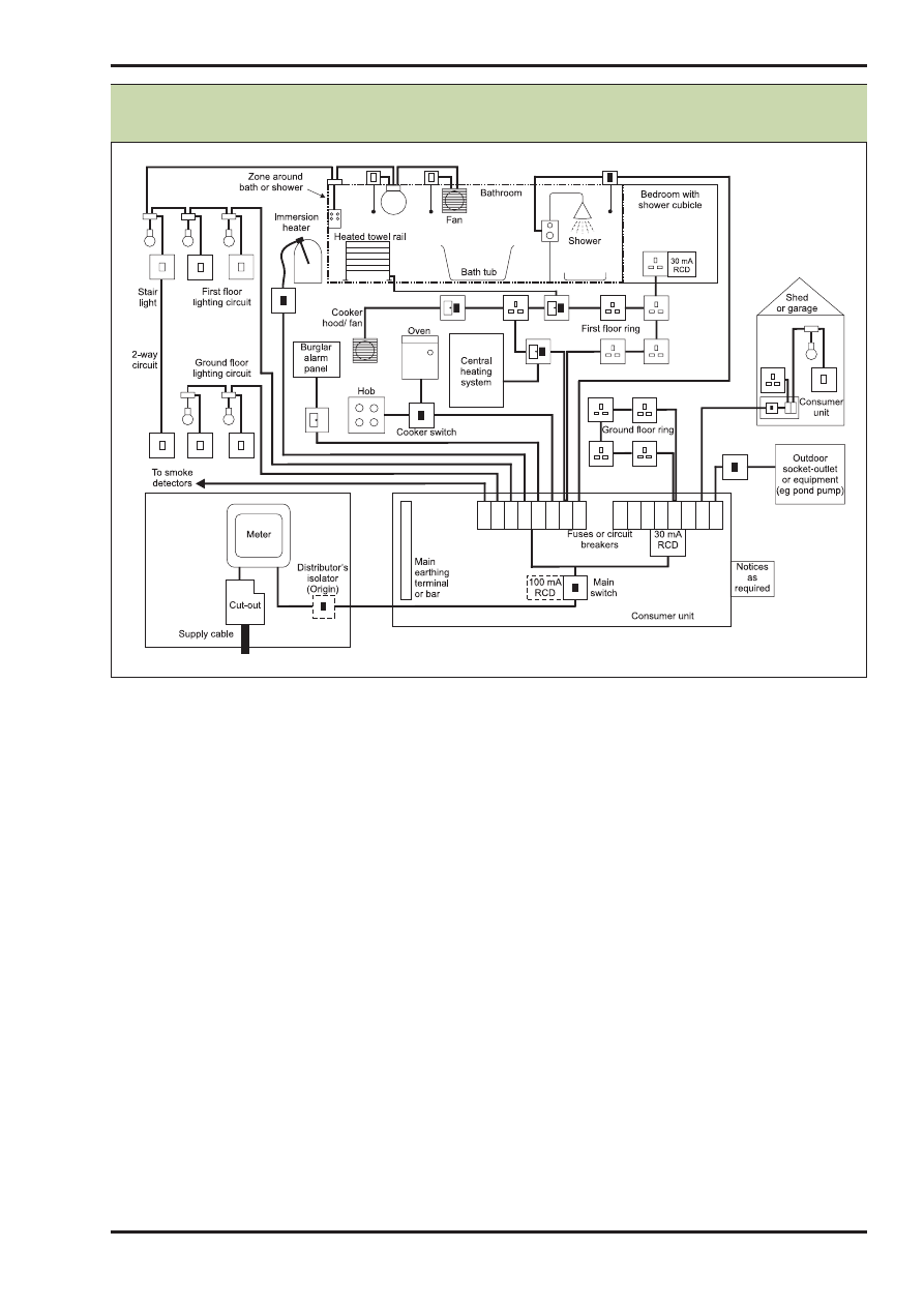
Diagram 1(a) indicates the many electrical
appliances that can be found in the home and
how they might be supplied.
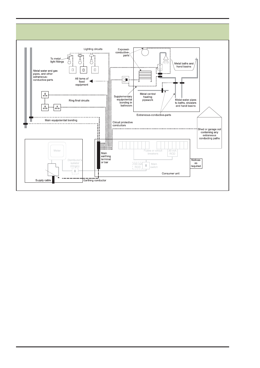
Diagram 1(b) indicates earthing and bonding
arrangements that can be necessary.
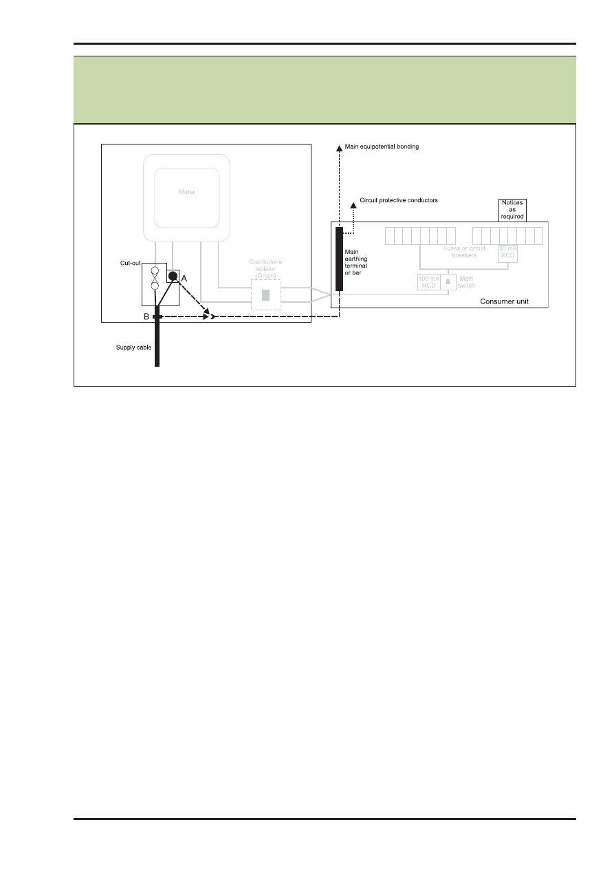
Diagram 2(a) indicates earthing arrangements
as might be provided by electricity distributors.
Diagram 2(b) indicates the earthing
arrangement as might need to be provided by
the consumer.
Appendix A: Examples of electrical
installation diagrams
EXAMPLES OF ELECTRICAL INSTALLATION DIAGRAMS
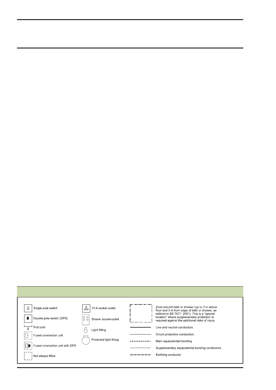
Key to Diagrams
Electrical safety
Approved Document P
15
P
ELECTRICAL SAFETY
Notes:
1. See the general rules in BS 7671: 2001.
2. The RCD component in the main switch is required for TT systems (see Diagram 2(b)). Individual circuit 30 mA RCDs may be
required to avoid unnecessary tripping.
3. The notices include advice on periodic testing and regular test operation of the RCDs.
4. The zone shown around the bath or shower corresponds to zone 3 in Section 601 of BS 7671: 2001.
The socket-outlet shown in the bedroom with the shower cubicle must be outside zone 3.
Diagram 1(a): Illustration of the fixed electrical installation that might be commonly
encountered in new or upgraded existing dwellings
Approved Document P
Electrical safety
16
P
Notes:
1. See the general rules in BS 7671: 2001.
2. Circuit protective conductors are taken to all items of fixed electrical equipment and local isolation and switching devices
which appear in Diagram 1(a).
3. In the case of a protective multiple earthing (PME) supply (see Diagram 2(a)), consult the electricity distributor.
4. Supplementary bonding is required in bathrooms to an extent dependent upon the presence of metallic fixtures, fittings and
pipework: see Section 601 of BS 7671: 2001.
EXAMPLES OF ELECTRICAL INSTALLATION DIAGRAMS
See Diagrams
2(a) and 2(b) for
details of earth
termination
arrangement
Diagram 1(b): Illustration of the earthing and bonding conductors that might be part
of the electrical installation shown in Diagram 1(a)
Electrical safety
Approved Document P
17
P
ELECTRICAL SAFETY
Notes:
1. Connection A shows the arrangement where an electricity distributor provides a combined protective earthing and neutral
conductor as part of a protective multiple earthing system (referred to as TN-C-S).
Connection B shows the arrangement where an electricity distributor provides a protective earthing conductor (usually the
metallic covering of the supply cable) that is separate from the neutral conductor (as part of a system referred to as TN-S).
2. Connections A or B can only be made by the electricity distributor or its appointed agent.
Diagram 2(a): Example earthing arrangement where the electricity distributor
provides the earth connection (referred to as TN-C-S where the connection is
made to A, or TN-S where the connection is made to B – the most common
systems in urban areas)
Approved Document P
Electrical safety
18
P
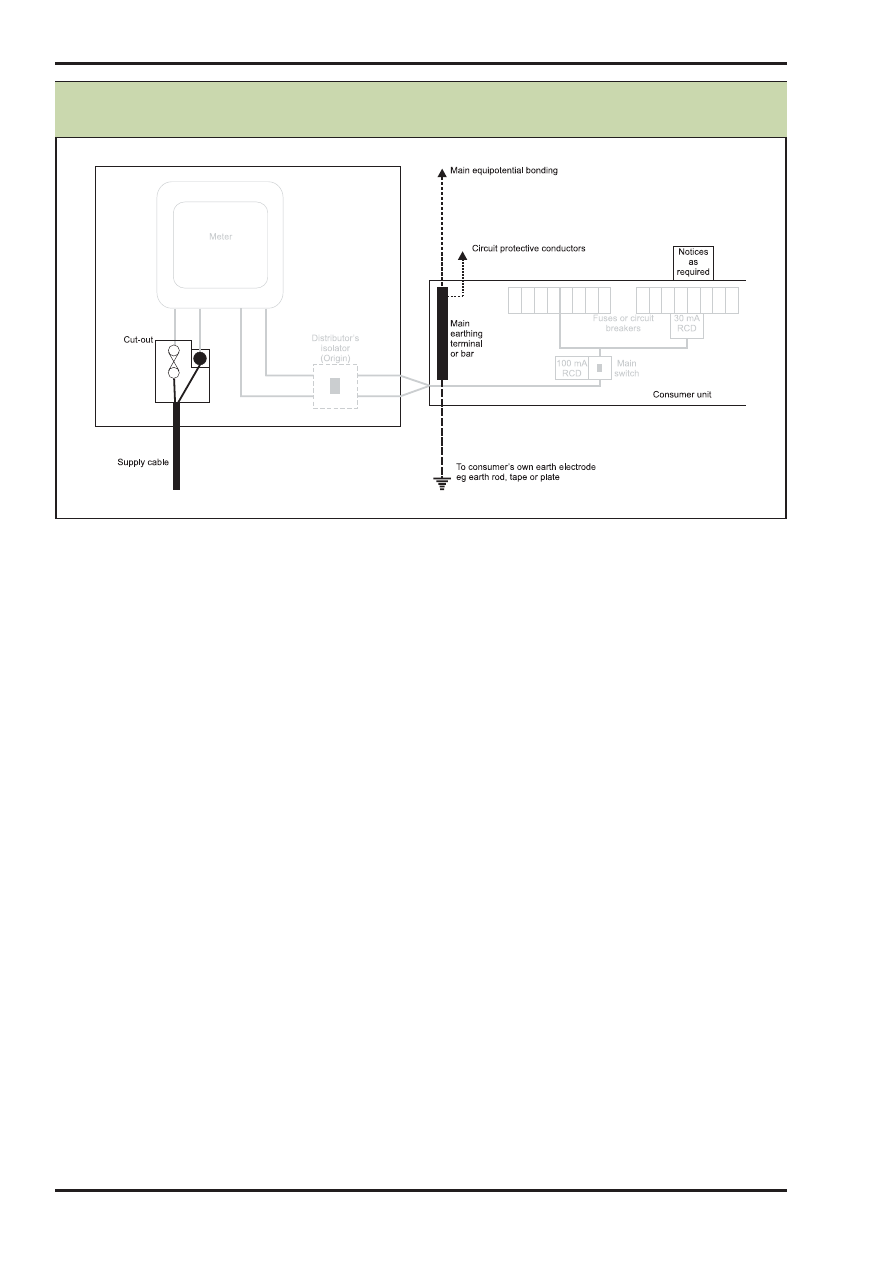
Notes:
1. BS 7671: 2001 requires that the part of the installation between the origin and the first RCD shall comply with the
requirements for protection by Class II equipment or equivalent insulation. For the arrangement shown, this applies to
the consumer unit and the wiring connecting it to the supplier’s equipment.
2. The 100 mA RCD component of the main switch should be of the time delayed type.
EXAMPLES OF ELECTRICAL INSTALLATION DIAGRAMS
Diagram 2(b): Example earthing arrangement where consumers provide their own
earthing connection (referred to as a TT system)

Electrical safety
Approved Document P
19
P
The BS 7671 and IEE forms and notes on the
following pages are taken from IEE Guidance
Note 3, 2002 edition, and are available for
downloading from the IEE website at
www.iee.org/Publish/WireRegs/forms.cfm.
They appear in the order:
Introduction
1.
Introduction to Appendix 6 of BS 7671:
2001 (Model forms for certification and
reporting)
Initial inspection and testing
2.
Notes for short form and full versions of
Electrical Installation Certificate
3.
Form 1 - Short form of Electrical
Installation Certificate (for use when one
person is responsible for the design,
construction, inspection and testing of an
installation), including guidance for recipients
4.
Form 2 - Full Electrical Installation
Certificate, including guidance for recipients
(standard form from Appendix 6 of BS 7671)
5.
Form 3 - Schedule of Inspections (from
Appendix 6 of BS 7671) with notes
6.
Form 4 - Schedule of Test Results (from
Appendix 6 of BS 7671) with notes
Minor works
7.
Notes on completion of Minor Electrical
Installation Works Certificate
8.
Form 5 - Minor Electrical Installation
Works Certificate, including guidance for
recipients (from Appendix 6 of
BS 7671)
COPIES OF BS 7671 AND IEE MODEL FORMS
Appendix B: Copies of BS 7671 and IEE
model forms

Approved Document P
Electrical safety
20
P
CERTIFICATION AND REPORTING
INTRODUCTION
(i)
The Electrical Installation Certificate required by Part 7 of BS 7671 shall be made out
and signed or otherwise authenticated by a competent person or persons in respect of
the design, construction, inspection and testing of the work.
(ii)
The Minor Works Certificate required by Part 7 of BS 7671 shall be made out and
signed or otherwise authenticated by a competent person in respect of the inspection
and testing of an installation.
(iii)
The Periodic Inspection Report required by Part 7 of BS 7671 shall be made out and
signed or otherwise authenticated by a competent person in respect of the inspection
and testing of an installation.
(iv)
Competent persons will, as appropriate to their function under (i) (ii) and (iii) above,
have a sound knowledge and experience relevant to the nature of the work undertaken
and to the technical standards set down in this British Standard, be fully versed in the
inspection and testing procedures contained in this Standard and employ adequate
testing equipment.
(v)
Electrical Installation Certificates will indicate the responsibility for design,
construction, inspection and testing, whether in relation to new work or further work on
an existing installation.
Where design, construction and inspection and testing is the responsibility of one
person a Certificate with a single signature declaration in the form shown below may
replace the multiple signatures section of the model form.
FOR DESIGN, CONSTRUCTION, INSPECTION & TESTING.
I being the person responsible for the Design, Construction, Inspection & Testing
of the electrical installation (as indicated by my signature below), particulars of
which are described above, having exercised reasonable skill and care when
carrying out the Design, Construction, Inspection & Testing, hereby CERTIFY that
the said work for which I have been responsible is to the best of my knowledge
and belief in accordance with BS 7671 : ………., amended to .............(date) except
for the departures, if any, detailed as follows.
(vi)
A Minor Works Certificate will indicate the responsibility for design, construction,
inspection and testing of the work described in Part 4 of the certificate.
(vii)
A Periodic Inspection Report will indicate the responsibility for the inspection and
testing of an installation within the extent and limitations specified on the report.
(viii)
A schedule of inspections and a schedule of test results as required by Part 7 (of BS
7671) shall be issued with the associated Electrical Installation Certificate or Periodic
Inspection Report.
(ix)
When making out and signing a form on behalf of a company or other business entity,
individuals shall state for whom they are acting.
(x)
Additional forms may be required as clarification, if needed by non-technical persons,
or in expansion, for larger or more complex installations.
(xi)
The IEE Guidance Note 3 provides further information on inspection and testing on
completion and for periodic inspections.
COPIES OF BS 7671 AND IEE MODEL FORMS

Electrical safety
Approved Document P
21
P
ELECTRICAL INSTALLATION CERTIFICATES
NOTES FOR FORMS 1 AND 2
1.
The Electrical Installation Certificate is to be used only for the initial certification of a new installation or
for an alteration or addition to an existing installation where new circuits have been introduced.
It is not to be used for a Periodic Inspection for which a Periodic Inspection Report form should be
used. For an alteration or addition which does not extend to the introduction of new circuits, a Minor
Electrical Installation Works Certificate may be used.
The original Certificate is to be given to the person ordering the work (Regulation 742-01-03). A
duplicate should be retained by the contractor.
2.
This Certificate is only valid if accompanied by the Schedule of Inspections and the Schedule(s) of Test
Results.
3.
The signatures appended are those of the persons authorised by the companies executing the work of
design, construction and inspection and testing respectively. A signatory authorised to certify more than
one category of work should sign in each of the appropriate places.
4.
The time interval recommended before the first periodic inspection must be inserted (see IEE Guidance
Note 3 for guidance).
5.
The page numbers for each of the Schedules of Test Results should be indicated, together with the total
number of sheets involved.
6.
The maximum prospective fault current recorded should be the greater of either the short-circuit current
or the earth fault current.
7.
The proposed date for the next inspection should take into consideration the frequency and quality of
maintenance that the installation can reasonably be expected to receive during its intended life, and the
period should be agreed between the designer, installer and other relevant parties.
COPIES OF BS 7671 AND IEE MODEL FORMS
Approved Document P
Electrical safety
22
P
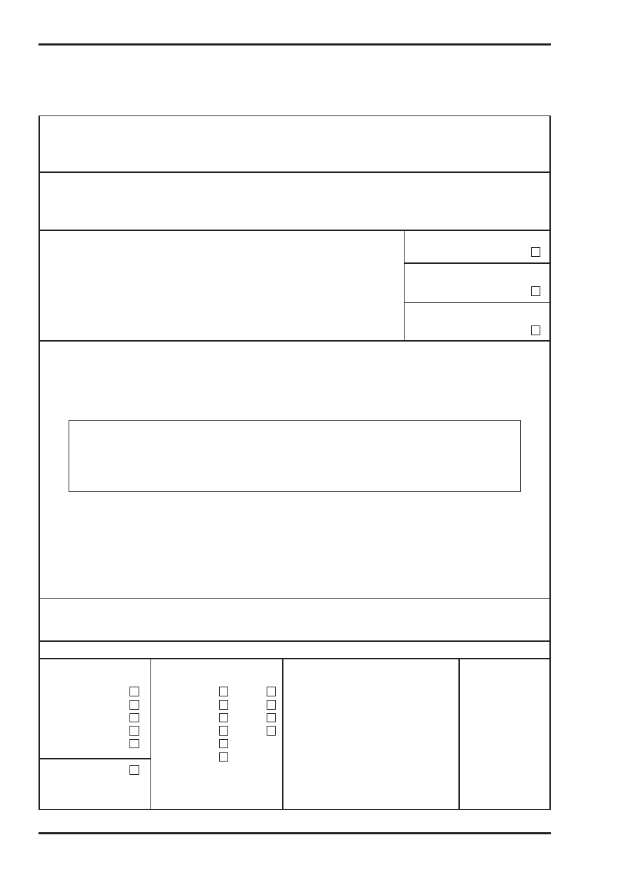
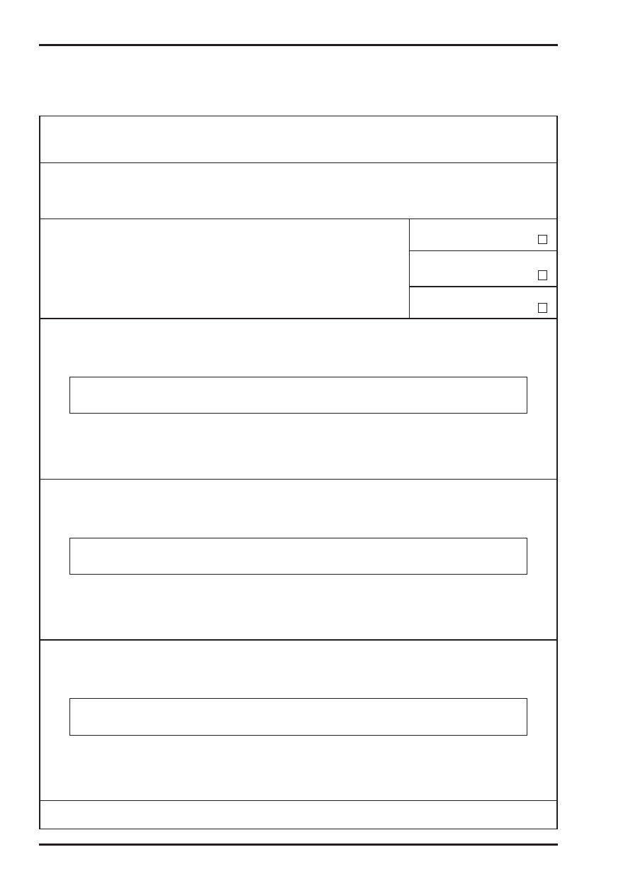
Form 1
Form No /1
ELECTRICAL INSTALLATION CERTIFICATE (notes 1 and 2)
(REQUIREMENTS FOR ELECTRICAL INSTALLATIONS - BS 7671 [IEE WIRING REGULATIONS])
DETAILS OF THE CLIENT (note 1)
........................................................................................................................................
........................................................................................................................................
........................................................................................................................................
INSTALLATION ADDRESS
........................................................................................................................................
........................................................................................................................................
..........................................................Postcode ..............................................................
DESCRIPTION AND EXTENT OF THE INSTALLATION Tick boxes as appropriate
Description of installation:
................................................................................
New installation
Extent of installation covered by this Certificate: ........................................................
....................................................................................................................................
Addition to an
....................................................................................................................................
existing installation
....................................................................................................................................
....................................................................................................................................
Alteration to an
....................................................................................................................................
existing installation
FOR DESIGN, CONSTRUCTION, INSPECTION & TESTING
I being the person responsible for the Design, Construction, Inspection & Testing of the electrical installation (as indicated
by my signature below), particulars of which are described above, having exercised reasonable skill and care when carrying
out the Design, Construction, Inspection & Testing, hereby CERTIFY that the said work for which I have been responsible is
to the best of my knowledge and belief in accordance with BS 7671 : ……., amended to .......... (date) except for the
departures, if any, detailed as follows:
Details of departures from BS 7671 (Regulations 120-01-03, 120-02):
The extent of liability of the signatory is limited to the work described above as the subject of this Certificate.
Name (IN BLOCK LETTERS):............................................................
Position: ................................................................
Signature (note 3): ..........................................................................
Date: ......................................................................
For and on behalf of: ......................................................................
Address: ..........................................................................................
........................................................................................................
......................................................................Postcode ..................
Tel No: ..................................................................
NEXT INSPECTION
I recommend that this installation is further inspected and tested after an interval of not more than ............ years/months
(notes 4 and 7)
SUPPLY CHARACTERISTICS AND EARTHING ARRANGEMENTS Tick boxes and enter details, as appropriate
Earthing arrangements
Number and Type of
Nature of Supply Parameters
Supply Protective
Live Conductors
Device Characteristics
TN-C
a.c.
d.c
Nominal voltage, U/Uo
(1)
..............................V
TN-S
1-phase, 2-wire
2-pole
Nominal frequency, f
(1)
..............................Hz
Type: ..........................
TN-C-S
1-phase, 3-wire
3-pole
Prospective fault current, Ipf
(2)
(note 6)
........kA
..................................
TT
2-phase, 3-wire
other
External loop impedance, Ze
(2)
....................
Ω
IT
3-phase, 3-wire
(Note: (1) by enquiry, (2) by enquiry or by measurement)
Nominal current rating
3-phase, 4-wire
................................A
Alternative source
of supply (to be detailed
on attached schedules)
COPIES OF BS 7671 AND IEE MODEL FORMS

Electrical safety
Approved Document P
23
P
PARTICULARS OF INSTALLATION REFERRED TO IN THE CERTIFICATE Tick boxes and enter details, as appropriate
Means of Earthing
Maximum Demand
Distributor’s facility
Maximum demand (load) .........................................................Amps per phase
Details of Installation Earth Electrode (where applicable)
Installation
Type
Location
Electrode resistance to earth
earth electrode
(e.g. rod(s), tape etc)
................................
....................................
..............................................
Ω
Main Protective Conductors
Earthing conductor:
material ............................ csa ................................mm
2
connection verified
Main equipotential
bonding conductors
material ............................ csa ................................mm
2
connection verified
To incoming water and/or gas service
To other elements ........................................................................
Main Switch or Circuit-breaker
BS, Type ..........................
No. of poles ..................
Current rating ..................A
Voltage rating ..........................V
Location ......................................................................................................................
Fuse rating or setting ..............A
Rated residual operating current I
∆
n
= ...................... mA, and operating time of ............ms (at I
∆
n
)
(applicable only where an RCD is suitable and is used as a main circuit-breaker)
COMMENTS ON EXISTING INSTALLATION: (In the case of an alteration or additions see Section 743)
............................................................................................................................................................................................
............................................................................................................................................................................................
............................................................................................................................................................................................
............................................................................................................................................................................................
............................................................................................................................................................................................
............................................................................................................................................................................................
............................................................................................................................................................................................
............................................................................................................................................................................................
SCHEDULES (note 2)
The attached Schedules are part of this document and this Certificate is valid only when they are attached to it.
............ Schedules of Inspections and ............ Schedules of Test Results are attached.
(Enter quantities of schedules attached)
GUIDANCE FOR RECIPIENTS
This safety Certificate has been issued to confirm that the electrical installation work to which it relates has
been designed, constructed and inspected and tested in accordance with British Standard 7671 (The IEE
Wiring Regulations).
You should have received an original Certificate and the contractor should have retained a duplicate
Certificate. If you were the person ordering the work, but not the user of the installation, you should pass this
Certificate, or a full copy of it including the schedules, immediately to the user.
The "original" Certificate should be retained in a safe place and be shown to any person inspecting or
undertaking further work on the electrical installation in the future. If you later vacate the property, this
Certificate will demonstrate to the new owner that the electrical installation complied with the requirements of
British Standard 7671 at the time the Certificate was issued. The Construction (Design and Management)
Regulations require that for a project covered by those Regulations, a copy of this Certificate, together with
schedules is included in the project health and safety documentation.
For safety reasons, the electrical installation will need to be inspected at appropriate intervals by a
competent person. The maximum time interval recommended before the next inspection is stated on Page 1
under "Next Inspection".
This Certificate is intended to be issued only for a new electrical installation or for new work associated with
an alteration or addition to an existing installation. It should not have been issued for the inspection of an
existing electrical installation. A "Periodic Inspection Report" should be issued for such a periodic inspection.
COPIES OF BS 7671 AND IEE MODEL FORMS
Approved Document P
Electrical safety
24
P
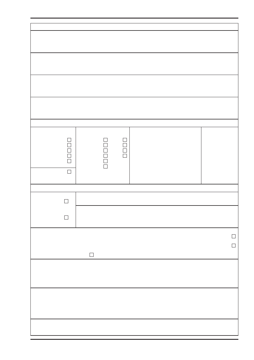
Form 2
Form No /2
ELECTRICAL INSTALLATION CERTIFICATE (notes 1 and 2)
(REQUIREMENTS FOR ELECTRICAL INSTALLATIONS - BS 7671 [IEE WIRING REGULATIONS])
DETAILS OF THE CLIENT
(note 1)
........................................................................................................................................
........................................................................................................................................
........................................................................................................................................
INSTALLATION ADDRESS
........................................................................................................................................
........................................................................................................................................
..........................................................Postcode ..............................................................
DESCRIPTION AND EXTENT OF THE INSTALLATION Tick boxes as appropriate
(note 1)
New installation
Description of installation:
................................................................................
Extent of installation covered by this Certificate: ........................................................
Addition to an
....................................................................................................................................
existing installation
....................................................................................................................................
....................................................................................................................................
Alteration to an
....................................................................................................................................
existing installation
FOR DESIGN
I/We being the person(s) responsible for the design of the electrical installation (as indicated by my/our signatures below), particulars of
which are described above, having exercised reasonable skill and care when carrying out the design, hereby CERTIFY that the design work
for which I/we have been responsible is to the best of my/our knowledge and belief in accordance with BS 7671 : ……., amended to ..........
(date) except for the departures, if any, detailed as follows:
Details of departures from BS 7671 (Regulations 120-01-03, 120-02):
The extent of liability of the signatory or the signatories is limited to the work described above as the subject of this Certificate.
For the DESIGN of the installation:
**
(Where there is mutual responsibility for the design)
Signature: .......................................... Date ....................
Name
(BLOCK LETTERS):
..................................................................
Designer No 1
Signature: .......................................... Date ....................
Name
(BLOCK LETTERS):
..................................................................
Designer No 2**
FOR CONSTRUCTION
I/We being the person(s) responsible for the construction of the electrical installation (as indicated by my/our signatures below), particulars
of which are described above, having exercised reasonable skill and care when carrying out the construction, hereby CERTIFY that the
construction work for which I/we have been responsible is to the best of my/our knowledge and belief in accordance with BS 7671 : …….,
amended to .......... (date) except for the departures, if any, detailed as follows:
Details of departures from BS 7671 (Regulations 120-01-03, 120-02):
The extent of liability of the signatory is limited to the work described above as the subject of this Certificate.
For CONSTRUCTION of the installation:
Signature: ............................................................................................
Date ....................
Name
(BLOCK LETTERS):
................................................................................................................................................................
Constructor
FOR INSPECTION & TESTING
I/We being the person(s) responsible for the inspection & testing of the electrical installation (as indicated by my/our signatures below),
particulars of which are described above, having exercised reasonable skill and care when carrying out the inspection & testing, hereby
CERTIFY that the work for which I/we have been responsible is to the best of my knowledge and belief in accordance with BS 7671 : …….,
amended to .......... (date) except for the departures, if any, detailed as follows:
Details of departures from BS 7671 (Regulations 120-01-03, 120-02):
The extent of liability of the signatory is limited to the work described above as the subject of this Certificate.
For INSPECTION & TEST of the installation:
**
(Where there is mutual responsibility for the design)
Signature: ............................................................................................
Date ....................
Name
(BLOCK LETTERS):
................................................................................................................................................................
Inspector
NEXT INSPECTION (notes 4 and 7)
I/We the designer(s) recommend that this installation is further inspected and tested after an interval of not more than ............ years/months
COPIES OF BS 7671 AND IEE MODEL FORMS
Electrical safety
Approved Document P
25
P
PARTICULARS OF THE SIGNATORIES TO THE ELECTRICAL INSTALLATION CERTIFICATE (note 3)
Designer (No 1)
Name: ........................................................
Company: ................................................................................................
Address: ............................................................................................................................................................................
....................................................................
Postcode: ................................
Tel No: ..............................................
Designer (No 2)
(if applicable)
Name: ........................................................
Company: ................................................................................................
Address: ............................................................................................................................................................................
....................................................................
Postcode: ................................
Tel No: ..............................................
Constructor
Name: ........................................................
Company: ................................................................................................
Address: ............................................................................................................................................................................
....................................................................
Postcode: ................................
Tel No: ..............................................
Inspector
Name: ........................................................
Company: ................................................................................................
Address: ............................................................................................................................................................................
....................................................................
Postcode: ................................
Tel No: ..............................................
SUPPLY CHARACTERISTICS AND EARTHING ARRANGEMENTS Tick boxes and enter details, as appropriate
Earthing arrangements
Number and Type of
Nature of Supply Parameters
Supply Protective
Live Conductors
Device Characteristics
TN-C
a.c.
d.c
Nominal voltage, U/Uo
(1)
..............................V
TN-S
1-phase, 2-wire
2-pole
Nominal frequency, f
(1)
..............................Hz
Type: ..........................
TN-C-S
1-phase, 3-wire
3-pole
Prospective fault current, Ipf
(2)
(note 6)
........kA
..................................
TT
2-phase, 3-wire
other
External loop impedance, Ze
(2)
....................
Ω
IT
3-phase, 3-wire
(Note: (1) by enquiry, (2) by enquiry or by measurement)
Nominal current rating
3-phase, 4-wire
................................A
Alternative source
of supply (to be detailed
on attached schedules)
PARTICULARS OF INSTALLATION REFERRED TO IN THE CERTIFICATE Tick boxes and enter details, as appropriate
Means of Earthing
Maximum Demand
Distributor’s facility
Maximum demand (load) .....................................................................Amps per phase
Details of Installation Earth Electrode (where applicable)
Installation
Type
Location
Electrode resistance to earth
earth electrode
(e.g. rod(s), tape etc)
....................................
..........................................
......................................................
Ω
Main Protective Conductors
Earthing conductor:
material .................................. csa ......................................mm
2
connection verified
Main equipotential
bonding conductors
material .................................. csa ......................................mm
2
connection verified
To incoming water and/or gas service
To other elements ......................................................................................
Main Switch or Circuit-breaker
BS, Type ................................
No. of poles ........................
Current rating ........................A
Voltage rating ..................................V
Location ........................................................................................................................................
Fuse rating or setting ......................A
Rated residual operating current I
∆
n
= ....... mA, and operating time of ................................................ms (at I
∆
n
)
(applicable only where an RCD is suitable and is used as a main circuit-breaker)
COMMENTS ON EXISTING INSTALLATION: (In the case of an alteration or additions see Section 743)
......................................................................................................................................................................................................................
......................................................................................................................................................................................................................
......................................................................................................................................................................................................................
......................................................................................................................................................................................................................
SCHEDULES (note 2)
The attached Schedules are part of this document and this Certificate is valid only when they are attached to it.
............ Schedules of Inspections and ............ Schedules of Test Results are attached.
(Enter quantities of schedules attached)
COPIES OF BS 7671 AND IEE MODEL FORMS

Approved Document P
Electrical safety
26
P
ELECTRICAL INSTALLATION CERTIFICATE
GUIDANCE FOR RECIPIENTS (to be appended to the Certificate)
This safety Certificate has been issued to confirm that the electrical installation work to which it relates has
been designed, constructed and inspected and tested in accordance with British Standard 7671 (The IEE
Wiring Regulations).
You should have received an original Certificate and the contractor should have retained a duplicate
Certificate. If you were the person ordering the work, but not the user of the installation, you should pass this
Certificate, or a full copy of it including the schedules, immediately to the user.
The "original" Certificate should be retained in a safe place and be shown to any person inspecting or
undertaking further work on the electrical installation in the future. If you later vacate the property, this
Certificate will demonstrate to the new owner that the electrical installation complied with the requirements of
British Standard 7671 at the time the Certificate was issued. The Construction (Design and Management)
Regulations require that for a project covered by those Regulations, a copy of this Certificate, together with
schedules is included in the project health and safety documentation.
For safety reasons, the electrical installation will need to be inspected at appropriate intervals by a competent
person. The maximum time interval recommended before the next inspection is stated on Page 1 under "Next
Inspection".
This Certificate is intended to be issued only for a new electrical installation or for new work associated with
an alteration or addition to an existing installation. It should not have been issued for the inspection of an
existing electrical installation. A "Periodic Inspection Report" should be issued for such a periodic inspection.
The Certificate is only valid if a Schedule of Inspections and Schedule of Test Result are appended.
COPIES OF BS 7671 AND IEE MODEL FORMS
Electrical safety
Approved Document P
27
P
Form 3
Form No /3
SCHEDULE OF INSPECTIONS
Methods of protection against
electric shock
(a)
Protection against both direct and indirect
contact:
(i)
SELV (note 1)
(ii)
Limitation of discharge of energy
(b)
Protection against direct contact: (note 2)
(i)
Insulation of live parts
(ii)
Barriers or enclosures
(iii) Obstacles (note 3)
(iv) Placing out of reach (note 4)
(v)
PELV
(vi) Presence of RCD for supplementary
protection
(c)
Protection against indirect contact:
(i)
EEBADS including:
Presence of earthing conductor
Presence of circuit protective conductors
Presence of main equipotential bonding
conductors
Presence of supplementary equipotential
bonding conductors
Presence of earthing arrangements for
combined protective and functional purposes
Presence of adequate arrangements for
alternative source(s), where applicable
Presence of residual current device(s)
(ii)
Use of Class II equipment or equivalent
insulation (note 5)
(iii) Non-conducting location: (note 6)
Absence of protective conductors
(iv) Earth-free equipotential bonding: (note 7)
Presence of earth-free equipotential bonding
conductors
(v)
Electrical separation (note 8)
Inspected by ..................................................................
Prevention of mutual detrimental influence
(a)
Proximity of non-electrical services and other
influences
(b)
Segregation of band I and band II circuits or
band II insulation used
(c)
Segregation of safety circuits
Identification
(a)
Presence of diagrams, instructions, circuit
charts and similar information
(b)
Presence of danger notices and other warning
notices
(c)
Labelling of protective devices, switches and
terminals
(d)
Identification of conductors
Cables and conductors
(a)
Routing of cables in prescribed zones or within
mechanical protection
(b)
Connection of conductors
(c)
Erection methods
(d)
Selection of conductors for current-carrying
capacity and voltage drop
(e)
Presence of fire barriers, suitable seals and
protection against thermal effects
General
(a)
Presence and correct location of appropriate
devices for isolation and switching
(b)
Adequacy of access to switchgear and other
equipment
(c)
Particular protective measures for special
installations and locations
(d)
Connection of single-pole devices for protection
or switching in phase conductors only
(e)
Correct connection of accessories and
equipment
(f)
Presence of undervoltage protective devices
(g)
Choice and setting of protective and
monitoring devices for protection against
indirect contact and/or overcurrent
(h)
Selection of equipment and protective
measures appropriate to external influences
(i)
Selection of appropriate functional switching
devices
Date ......................................................................
COPIES OF BS 7671 AND IEE MODEL FORMS
Notes:
T
to indicate an inspection has been carried out and the result is satisfactory
C
to indicate an inspection has been carried out and the result was unsatisfactory
N/A
to indicate the inspection is not applicable
LIM
to indicate that, exceptionally, a limitation agreed with the person ordering the work prevented the inspection or test being carried out
1.
SELV An extra-low voltage system which is electrically
separated from Earth and from other systems. The
particular requirements of the Regulations must be
checked (see Regulations 411-02 and 471-02)
2.
Method of protection against direct contact - will include
measurement of distances where appropriate
3.
Obstacles - only adopted in special circumstances (see
Regulations 412-04 and 471-06)
4.
Placing out of reach - only adopted in special
circumstances (see Regulations 412-05 and 471-07)
5.
Use of Class II equipment - infrequently adopted and
only when the installation is to be supervised (see
Regulations 413-03 and 471-09)
6.
Non-conducting locations - not applicable in domestic
premises and requiring special precautions (see
Regulations 413-04 and 471-10)
7.
Earth-free local equipotential bonding - not applicable in
domestic premises, only used in special circumstances
(see Regulations 413-05 and 471-11)
8.
Electrical separation (see Regulations 413-06 and 471-12)
Approved Document P
Electrical safety
28
P
COPIES OF BS 7671 AND IEE MODEL FORMS
Form 4
Form No /4
SCHEDULE OF TEST RESUL
TS
Contractor:
......................................................
Addr
ess/Location of distribution boar
d:
Instruments
T
est Date:
......................................................
..........................................................
* T
y
pe of Supply: TN-S/TN-C-S/TT
loop impedance:
........................................
..........................................................
* Ze at origin: ……….ohms
continuity:
.................................
.................
Signatur
e ......................................................
..........................................................
*
PFC
: ………….kA
insulation:
..................................................
Method of pr
otection against indir
ect contact:
................................................................................
..........................................
RCD tester:
................................................
Equipment vulnerable to testing:
..............................................................................................
..........................................................................................................................
Description of W
ork:
...............................................................................................................................
.................................................................
Cir
cuit Over
curr
ent
T
est
Results
Description
Device
*Short-cir
cuit
Wiring
Continuity
Insulation
Polarity
Earth
Functional
Remarks
capacity:
Conductors
Resistance
Loop
T
esting
……..kA
Impedance
type
Rating
live
cpc
(R
1
+ R
2
)*
R
2
*
Ring
Live/
Live/
Zs
RCD
Other
I
n
Live
Earth
time
Am
m
2
mm
2
ΩΩ
M
Ω
M
ΩΩ
ms
12
3
4
5
*6
*7
*8*
9
*10
*11
*12
*13
*14
15
Deviations fr
om Wiring Regulations and special notes:
* See notes on schedule of test r
esults

Electrical safety
Approved Document P
29
P
NOTES ON SCHEDULE OF TEST RESULTS
*
Type of supply is ascertained from the supply company or by inspection.
*
Ze at origin. When the maximum value declared by the electricity supplier is used, the effectiveness of
the earth must be confirmed by a test. If measured the main bonding will need to be disconnected for the
duration of the test.
*
Short-circuit capacity of the device is noted, see Table 7.2A of the On-Site Guide or 2.7.15 of GN3
*
Prospective fault current (PFC). The value recorded is the greater of either the short-circuit current or the
earth fault current. Preferably determined by enquiry of the supplier.
The following tests, where relevant, shall be carried out in the following sequence:
Continuity of protective conductors, including main and supplementary bonding
Every protective conductor, including main and supplementary bonding conductors, should be tested to
verify that it is continuous and correctly connected.
*6
Continuity
Where Test Method 1 is used, enter the measured resistance of the phase conductor plus the circuit protective
conductor (R1+ R2).
See 10.3.1 of the On-Site Guide or 2.7.5 of GN3.
During the continuity testing (Test Method 1) the following polarity checks are to be carried out:
(a)
every fuse and single-pole control and protective device is connected in the phase conductor only
(b )
centre-contact bayonet and Edison screw lampholders have outer contact connected to the neutral
conductor
(c)
wiring is correctly connected to socket-outlets and similar accessories.
Compliance is to be indicated by a tick in polarity column 11.
(R1 + R2) need not be recorded if R2 is recorded in column 7.
*7
Where Test Method 2 is used, the maximum value of R2 is recorded in column 7.
Where the alternative method of Regulation 413-02-12 is used for shock protection, the resistance of the
circuit protective conductor R2 is measured and recorded in column 7.
See 10.3.1 of the On-Site Guide or 2.7.5 of GN3.
*8
Continuity of ring final circuit conductors
A test shall be made to verify the continuity of each conductor including the protective conductor of every
ring final circuit.
See 10.3.2 of the On-Site Guide or 2.7.6 of GN3.
*9, *10 Insulation Resistance
All voltage sensitive devices to be disconnected or test between live conductors (phase and neutral)
connected together and earth.
The insulation resistance between live conductors is to be inserted in column 9.
The minimum insulation resistance values are given in Table 10.1 of the On-Site Guide or Table 2.2 of GN3.
See 10.3.3(iv) of the On-Site Guide or 2.7.7 of GN3.
All the preceding tests should be carried out before the installation is energised.
*11
Polarity
A satisfactory polarity test may be indicated by a tick in column 11.
Only in a Schedule of Test Results associated with a Periodic Inspection Report is it acceptable to record
incorrect polarity.
COPIES OF BS 7671 AND IEE MODEL FORMS

Approved Document P
Electrical safety
30
P
*12
Earth fault loop impedance Zs
This may be determined either by direct measurement at the furthest point of a live circuit or by adding
(R1 + R2) of column 6 to Ze. Ze is determined by measurement at the origin of the installation or
preferably the value declared by the supply company used.
Zs = Ze + (R1 + R2). Zs should be less than the values given in Appendix 2 of the On-Site Guide or App
2 of GN3.
*13
Functional testing
The operation of RCDs (including RCBOs) shall be tested by simulating a fault condition, independent of
any test facility in the device.
Record operating time in column 13. Effectiveness of the test button must be confirmed.
See Section 11 of the On-Site Guide or 2.7.16 of GN3.
*14
All switchgear and controlgear assemblies, drives, control and interlocks, etc must be operated to
ensure that they are properly mounted, adjusted and installed.
Satisfactory operation is indicated by a tick in column 14.
Earth electrode resistance
The earth electrode resistance of TT installations must be measured, and normally an RCD is required.
For reliability in service the resistance of any earth electrode should be below 200
Ω
. Record the value
on Form 1, 2 or 6, as appropriate.
See 10.3.5 of the On-Site Guide or 2.7.13 of GN3.
COPIES OF BS 7671 AND IEE MODEL FORMS

Electrical safety
Approved Document P
31
P
NOTES ON COMPLETION OF MINOR ELECTRICAL INSTALLATION WORKS
CERTIFICATE
Scope
The Minor Works Certificate is intended to be used for additions and alterations to an installation that do not
extend to the provision of a new circuit. Examples include the addition of a socket-outlet or a lighting point to
an existing circuit, the relocation of a light switch etc. This Certificate may also be used for the replacement of
equipment such as accessories or luminaires, but not for the replacement of distribution boards or similar
items. Appropriate inspection and testing, however, should always be carried out irrespective of the extent of
the work undertaken.
Part 1 Description of minor works
1,2
The minor works must be so described that the work that is the subject of the certification can be
readily identified.
4
See Regulations 120-01-03 and 120-02. No departures are to be expected except in most unusual
circumstances. See also Regulation 743-01-01.
Part 2 Installation details
2
The method of protection against indirect contact shock must be clearly identified, e.g. earthed
equipotential bonding and automatic disconnection of supply using fuse/circuit-breaker/RCD.
4
If the existing installation lacks either an effective means of earthing or adequate main equipotential
bonding conductors, this must be clearly stated. See Regulation 743-01-02.
Recorded departures from BS 7671 may constitute non-compliance with the Electricity Supply
Regulations 1988 as amended or the Electricity at Work Regulations 1989. It is important that the client
is advised immediately in writing.
Part 3 Essential tests
The relevant provisions of Part 7 (Inspection and Testing) of BS 7671 must be applied in full to all minor works.
For example, where a socket-outlet is added to an existing circuit it is necessary to:
1
establish that the earthing contact of the socket-outlet is connected to the main earthing terminal
2
measure the insulation resistance of the circuit that has been added to, and establish that it complies
with Table 71A of BS 7671
3
measure the earth fault loop impedance to establish that the maximum permitted disconnection time is
not exceeded
4
check that the polarity of the socket-outlet is correct
5
(if the work is protected by an RCD) verify the effectiveness of the RCD.
Part 4 Declaration
1,3
The Certificate shall be made out and signed by a competent person in respect of the design,
construction, inspection and testing of the work.
1,3
The competent person will have a sound knowledge and experience relevant to the nature of the work
undertaken and to the technical standards set down in BS 7671, be fully versed in the inspection and
testing procedures contained in the Regulations and employ adequate testing equipment.
2
When making out and signing a form on behalf of a company or other business entity, individuals shall
state for whom they are acting.
COPIES OF BS 7671 AND IEE MODEL FORMS
Approved Document P
Electrical safety
32
P
COPIES OF BS 7671 AND IEE MODEL FORMS
Form 5
MINOR ELECTRICAL INSTALLATION WORKS CERTIFICATE
(REQUIREMENTS FOR ELECTRICAL INSTALLATIONS - BS 7671 [IEE WIRING REGULATIONS])
To be used only for minor electrical work which does not include the provision of a new circuit
PART 1 : Description of minor works
1.
Description of the minor works : ................................................................................................................................
2.
Location/Address :......................................................................................................................................................
3.
Date minor works completed : ....................................................................................................................................
4.
Details of departures, if any, from BS 7671
..................................................................................................................................................................................
..................................................................................................................................................................................
..................................................................................................................................................................................
PART 2 : Installation details
1.
System earthing arrangement:
TN-C-S
TN-S
TT
2.
Method of protection against indirect contact: ............................................................................................................
3.
Protective device for the modified circuit:
Type BS ............................
Rating ..............................A
4.
Comments on existing installation, including adequacy of earthing and bonding arrangements:
(see Regulation 130-07) ..............................................................................................................................................
..................................................................................................................................................................................
..................................................................................................................................................................................
..................................................................................................................................................................................
PART 3 : Essential Tests
1.
Earth continuity : satisfactory
2.
Insulation resistance:
Phase/neutral ................................................M
Ω
Phase/earth ..................................................M
Ω
Neutral/earth ..................................................M
Ω
3.
Earth fault loop impedance
........................................................................
Ω
4.
Polarity : satisfactory
5.
RCD operation (if applicable): Rated residual operating current I
∆
n
..........mA and operating time of ..........ms (at I
∆
n
)
PART 4 : Declaration
1.
I/We CERTIFY that the said works do not impair the safety of the existing installation, that the said works have been
designed, constructed, inspected and tested in accordance with BS 7671 : ………. (IEE Wiring Regulations), amended
to ............................... and that the said works, to the best of my/our knowledge and belief, at the time of my/our
inspection, complied with BS 7671 except as detailed in Part 1.
2.
Name: ........................................................................
3. Signature: ..............................................................
For and on behalf of: ..................................................
Position: ................................................................
Address: ......................................................................
....................................................................................
Date: ....................................................................
....................................................................................
..................................................Postcode ..................

Electrical safety
Approved Document P
33
P
MINOR ELECTRICAL INSTALLATION WORKS CERTIFICATE
GUIDANCE FOR RECIPIENTS (to be appended to the Certificate)
This Certificate has been issued to confirm that the electrical installation work to which it relates has been
designed, constructed and inspected and tested in accordance with British Standard 7671 (The IEE Wiring
Regulations).
You should have received an original Certificate and the contractor should have retained a duplicate. If you
were the person ordering the work, but not the owner of the installation, you should pass this Certificate, or a
copy of it, to the owner.
A separate Certificate should have been received for each existing circuit on which minor works have been
carried out. This Certificate is not appropriate if you requested the contractor to undertake more extensive
installation work, for which you should have received an Electrical Installation Certificate.
The Certificate should be retained in a safe place and be shown to any person inspecting or undertaking
further work on the electrical installation in the future. If you later vacate the property, this Certificate will
demonstrate to the new owner that the minor electrical installation work carried out complied with the
requirements of British Standard 7671 at the time the Certificate was issued.
COPIES OF BS 7671 AND IEE MODEL FORMS
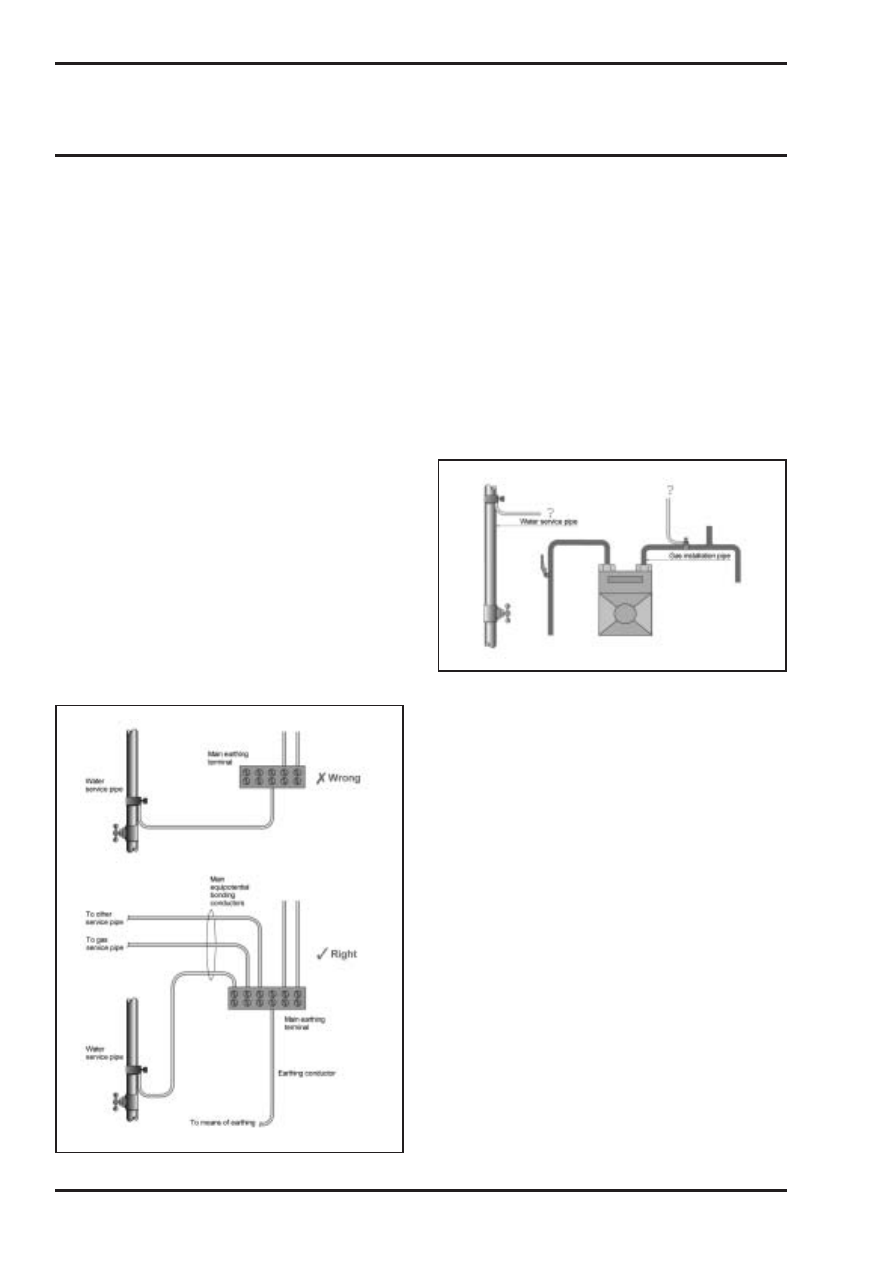
Approved Document P
Electrical safety
34
P
Appendix C: Older practice that can be
encountered in alteration work
When carrying out work on existing, older
installations, some features will be encountered
which differ from those found in modern
installations.
Electrical installations began to be
commonplace in domestic dwellings as early as
the 1920s, and over the years there have been
considerable changes to the types of wiring
materials and other equipment being installed,
and in the ways that electrical installations are
structured. From the electrical safety point of
view, these changes have had two main
causes: advances in technology, and
amendments to the Wiring Regulations
published by the Institution of Electrical
Engineers (issued as British Standard BS 7671
since 1992).
This appendix presents examples of the types
of features just mentioned, which may be
unfamiliar to those who find them and may be
a safety hazard. Also included, where
applicable, are comments about changes in the
Wiring Regulations relevant to the equipment
concerned.
Use of a gas, water or other
service pipe as an earth
(No proper means of earthing for the
electrical installation)
It is not permitted to use a gas, water or other
metal service pipe as a means of earthing for
an electrical installation. (This does not
preclude equipotential bonding connections to
these pipes.) It never has been permitted for
gas pipes, and has not been permitted for
other service pipes since 1966.
Every electrical installation requires a proper
means of earthing. The most usual type is an
electricity distributor’s earthing terminal, provided
for this purpose near the electricity meter.
Absence of, or inadequately sized,
main equipotential bonding
conductors
Prior to 1966 the Wiring Regulations contained
no requirements for main equipotential bonding.
Since then, the installation of main equipotential
bonding conductors has been required to water
service pipes, gas installation pipes, oil supply
pipes, and certain other ‘earthy’ metalwork that
may be present on the premises.
During the 1980s new Regulations were
introduced, requiring the minimum size of main
equipotential bonding conductors to be larger
than previously called for, particularly where
there is a PME (protective multiple earthing)
electricity supply. For most dwellings the
minimum size now permitted to be installed is
10 mm
2
.
OLDER PRACTICE AND ALTERATION WORK
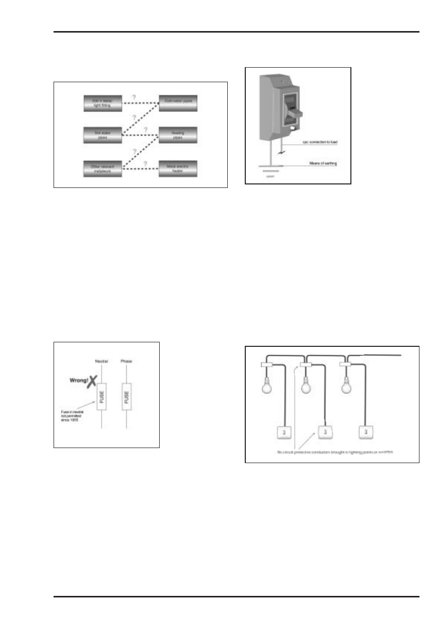
Electrical safety
Approved Document P
35
P
OLDER PRACTICE AND ALTERATION WORK
Absence of, or inadequately sized,
supplementary equipotential
bonding
Prior to 1981 there were virtually no
requirements in the Wiring Regulations for
supplementary equipotential bonding
conductors.
Since then, the installation of supplementary
equipotential bonding conductors has been
required in installations and locations of
increased electric shock risk, such as
bathrooms and shower rooms.
During the 1980s and 1990s the requirements for
the sizing of supplementary equipotential
bonding conductors were amended. For most
dwellings the minimum size now permitted to be
installed without mechanical protection is 4 mm
2
.
Double-pole fusing
In many installations put in up to the 1950s,
the circuits have a fuse in the neutral
conductor as well as in the phase conductor.
This is a potentially dangerous practice for ac
installations, and ceased to be permitted by
the Wiring Regulations in about 1955.
In the event of a short-circuit, there is a 50%
chance that the fuse in the neutral conductor
will operate. When this happens, the phase
conductor is not automatically disconnected
from the faulty circuit as would now normally
be expected, thereby leaving a danger for
the unwary.
Voltage-operated earth-leakage
circuit-breakers
Two basic types of earth-leakage circuit-
breaker used to be recognised by the Wiring
Regulations: the current-operated type and the
voltage-operated type. Today, only the current-
operated type is recognised (now called
residual current devices or RCDs).
The voltage-operated type ceased to be
recognised in 1981. It can be distinguished by
its two separate earthing terminals – one for an
earthing connection to the load and one for an
earthing connection to a means of earthing
(often a driven rod). The major drawback with
this type of device is that a parallel earth path
can render it disabled.
No circuit protective conductors
in lighting circuits
Lighting circuits installed before 1966, and not
including any metalwork needing to be earthed,
often do not include a circuit protective
conductor. Consequently, any new or
replacement light fittings, switches or other
components must be of a type not requiring
earthing, eg non-metallic varieties, unless new
circuit protective (earthing) conductors are
provided. Otherwise, there will be a potential
danger of indirect contact (electric shock).
All lighting circuits installed since 1966 (with
the exception of certain extra-low voltage
circuits) have been required to include a circuit
protective conductor.
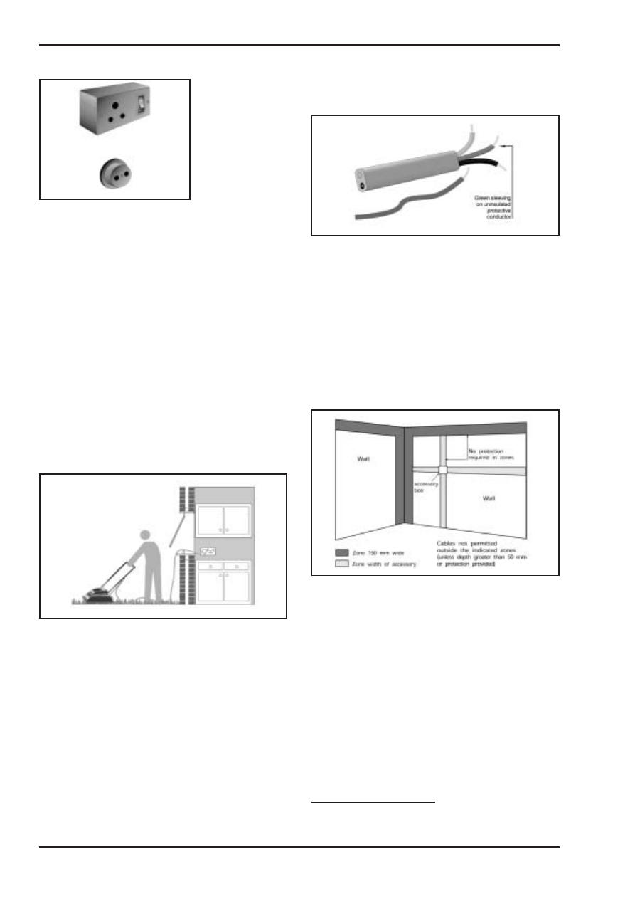
Approved Document P
Electrical safety
36
P
OLDER PRACTICE AND ALTERATION WORK
Non-13 A socket-outlets
The installation of socket-outlets other than the
current standard 13 A square-pinned type was
common prior to the early 1950s. These outlets
accept non-fused plugs (some with an earth pin
and some without), generally having round pins.
These older types of socket-outlet designed for
non-fused plugs must not be connected to a ring
circuit. Such an arrangement can be dangerous.
In addition, socket-outlets that will accept
unearthed (2-pin) plugs must not be used to
supply equipment needing to be earthed. It is
strongly recommended that such outlets be
taken out of service.
No RCD protection for socket-
outlets likely to supply portable
equipment outdoors
(or an insufficient number of such
socket-outlets so protected)
A person receiving an electric shock when
using portable electrical equipment outdoors
can be at great risk of death or serious injury.
The risk is significantly reduced if the socket-
outlet supplying the equipment is provided with
sensitive RCD protection (fitted either at the
socket-outlet itself or at the consumer unit).
However, prior to 1981 the Wiring Regulations
did not require such protection.
Nowadays, sensitive RCD protection
1
is
required for all socket-outlets which are
installed having a rating of 32 A or less, and
which may reasonably be expected to supply
portable equipment for use outdoors. The initial
requirement, in 1981, was for this protection to
be provided to at least one such socket-outlet.
However, this was found to be inadequate.
Green coloured protective
conductors or sleeving instead of
green-yellow
The Wiring Regulations used to accept the
single colour green for the identification of
protective conductors.
However, since 1977 a green-yellow coding has
been required for all protective conductors
installed.
The older green sleeving or tape should be
replaced with the new green-yellow striped
variety whenever connections are re-made.
Concealed cables outside of
permitted zones in walls
Until the latter part of the 1980s the Wiring
Regulations did not contain any specific
requirements for the positioning of cables
concealed in walls and partitions.
Today’s requirements are given in Regulation
522-06-06 in BS 7671, and are illustrated here.
To avoid striking a cable, extreme care should
always be taken in any activity that involves
penetrating a wall or partition, even when it is
known that any concealed cables were
installed in recent years. Where the cables
were installed prior to 1980 they are
particularly likely to be found outside of the
zones illustrated opposite. A cable and stud
detector should always be used before
attempting to drill into walls, floors or ceilings.
1
The RCD should have a rated residual operating
current of not more than 30 mA
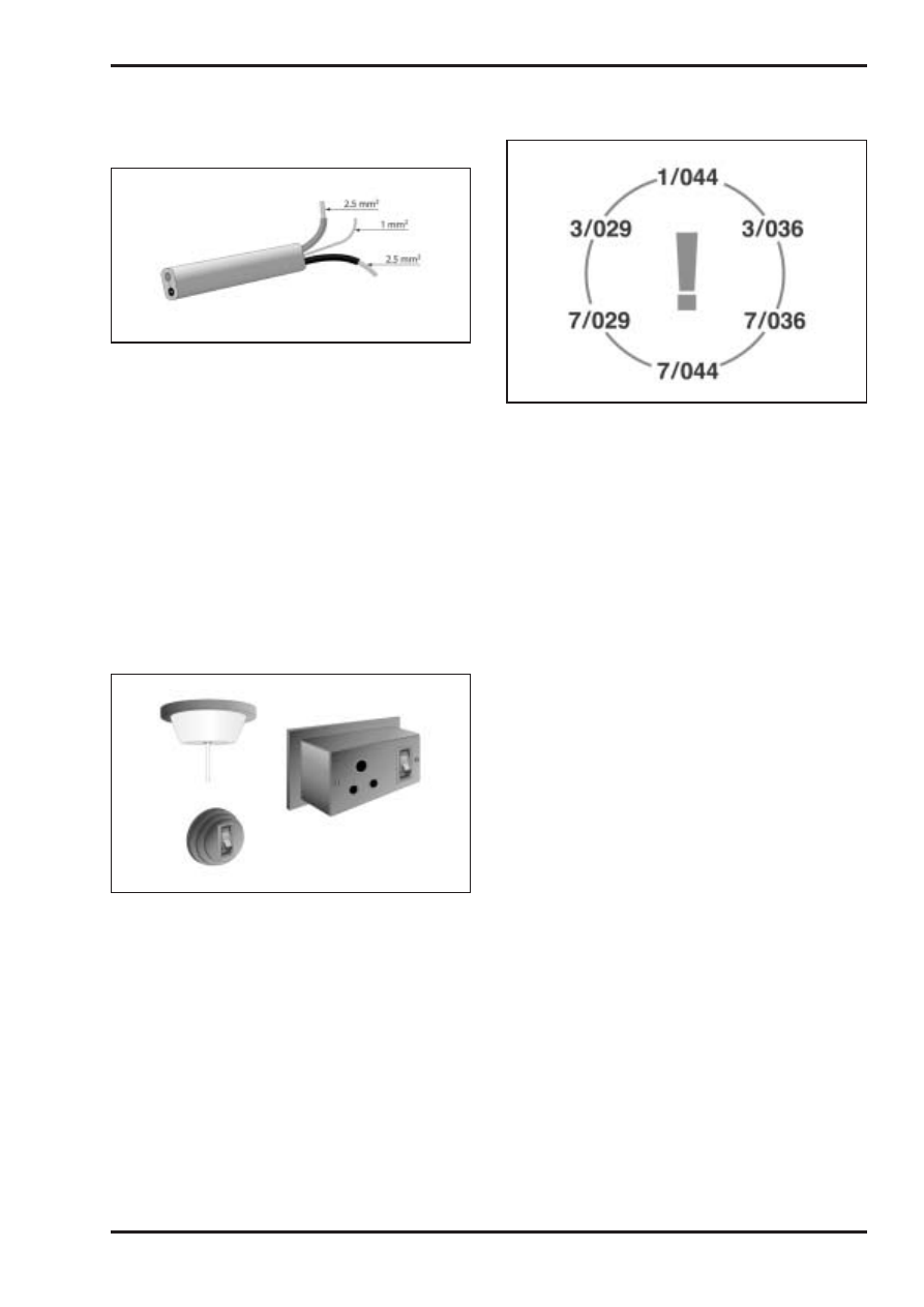
Electrical safety
Approved Document P
37
P
OLDER PRACTICE AND ALTERATION WORK
2.5 mm
2
twin-and-earth cables
incorporating circuit protective
conductor of only 1.0 mm
2
For some years, 2.5 mm
2
twin & earth pvc/pvc
cables to BS 6004 were manufactured with a
circuit protective conductor (cpc) of only 1 mm
2
,
rather than 1.5 mm
2
as is incorporated today.
The size of the cpc was increased to 1.5 mm
2
in BS 6004 because in certain circumstances
the 1 mm
2
cpc may not always be properly
protected against thermal effects in the event
of an earth fault. This is where the cable is
used in a ring final circuit protected by a 30 A
semi-enclosed (rewirable) fuse. If this is the
case, a competent electrician should be
consulted about upgrading the cables and/or
the consumer unit.
Accessories on wooden
mounting blocks
It was commonplace up to the mid 1960s for
accessories such as socket-outlets, lighting
switches and ceiling roses to be fixed to
wooden mounting blocks.
The design of the accessories is often such
that the wooden block is used to form part of
the enclosure for the unsheathed cores and
terminations of cables connecting to the
accessory. However, depending on the
particular characteristics of the material from
which the block is made, it may not satisfy the
ignitability requirements of the current Wiring
Regulations (BS 7671) for such use.
Cables of imperial (non-metric)
sizes
Up until the beginning of the 1970s, cables
could still be purchased having imperial, rather
than metric, sized conductors. Many such
cables are still to be found in older installations.
Their conductors may be single-stranded (as in
1/.044) or may have three, seven or more
strands (as in 3/.029, 7/.029 and 19/.044). To
the inexperienced eye these cables may be
difficult to recognise, other than perhaps by
comparison of their conductors with those of
metric cables. The important thing to
appreciate, however, is that their current
carrying capacity and voltage drop
characteristics are likely to be different from
those which may at first be expected. It would
therefore be prudent to engage a competent
electrician to establish whether the
performance limits are being exceeded, or
would be if a new appliance with a higher
rating (eg washing machine, dishwasher, towel
rail, appliances rated at more than 2 kW) were
to be connected.
Finally, it should be noted that copper
conductors of imperial cables may be of the
tinned type, giving them an unfamiliar colour.
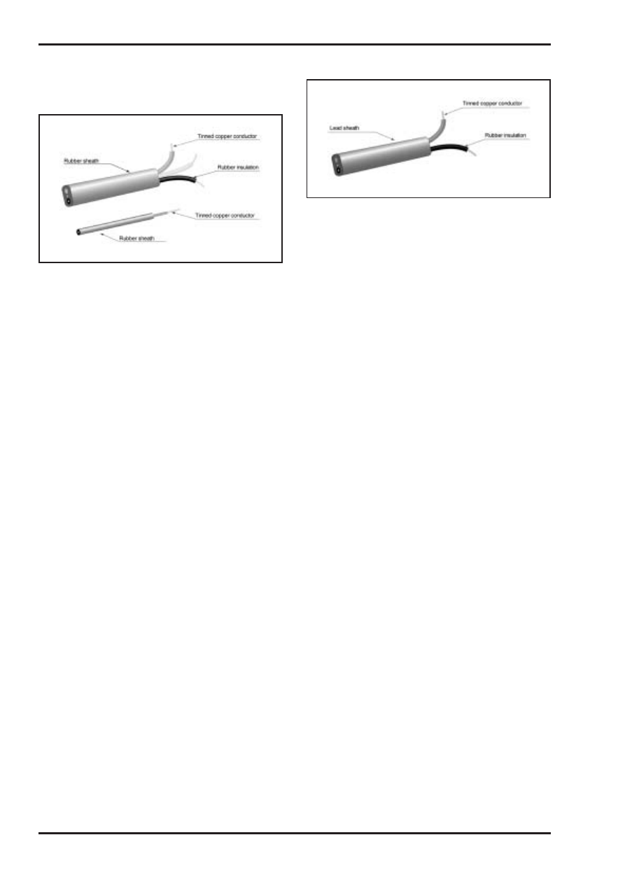
Approved Document P
Electrical safety
38
P
OLDER PRACTICE AND ALTERATION WORK
Tough rubber sheathed (TRS),
vulcanised rubber insulation
(VRI) cables
Prior to the use of pvc insulated cables
becoming common in the 1960s, most cables
installed in domestic dwellings were of the
rubber insulated, tough-rubber sheathed (TRS)
type. These are easily recognizable by their
black exterior.
The extent to which the insulation and sheath
deteriorate in service depends very much on
whether the cable has been subjected to
overloading and/or excessive temperature, or
the rubber has been exposed to direct sunlight.
Deterioration results in a loss of insulating
properties, with the rubber becoming dry and
inflexible – perhaps with a tendency to crumble.
Such wiring installations should be tested by a
competent person at the earliest opportunity,
but otherwise left undisturbed until
replacement, as they are beyond their normally
expected safe working life.
Lead-sheathed cables
Lead sheathed cables may be found in some
installations dating from before about 1948.
These have rubber insulated, tinned copper
conductors and an outer sheath of lead.
For reasons of protection against indirect
contact (electric shock) it is essential that the
lead sheath of every such cable is, and will
remain, properly earthed.
The conductor insulation, being made of
rubber, is prone to deterioration as described
above for TRS cables.
Again, such wiring installations should be
tested by a competent person at the earliest
opportunity as they are beyond their normally
expected safe working life.
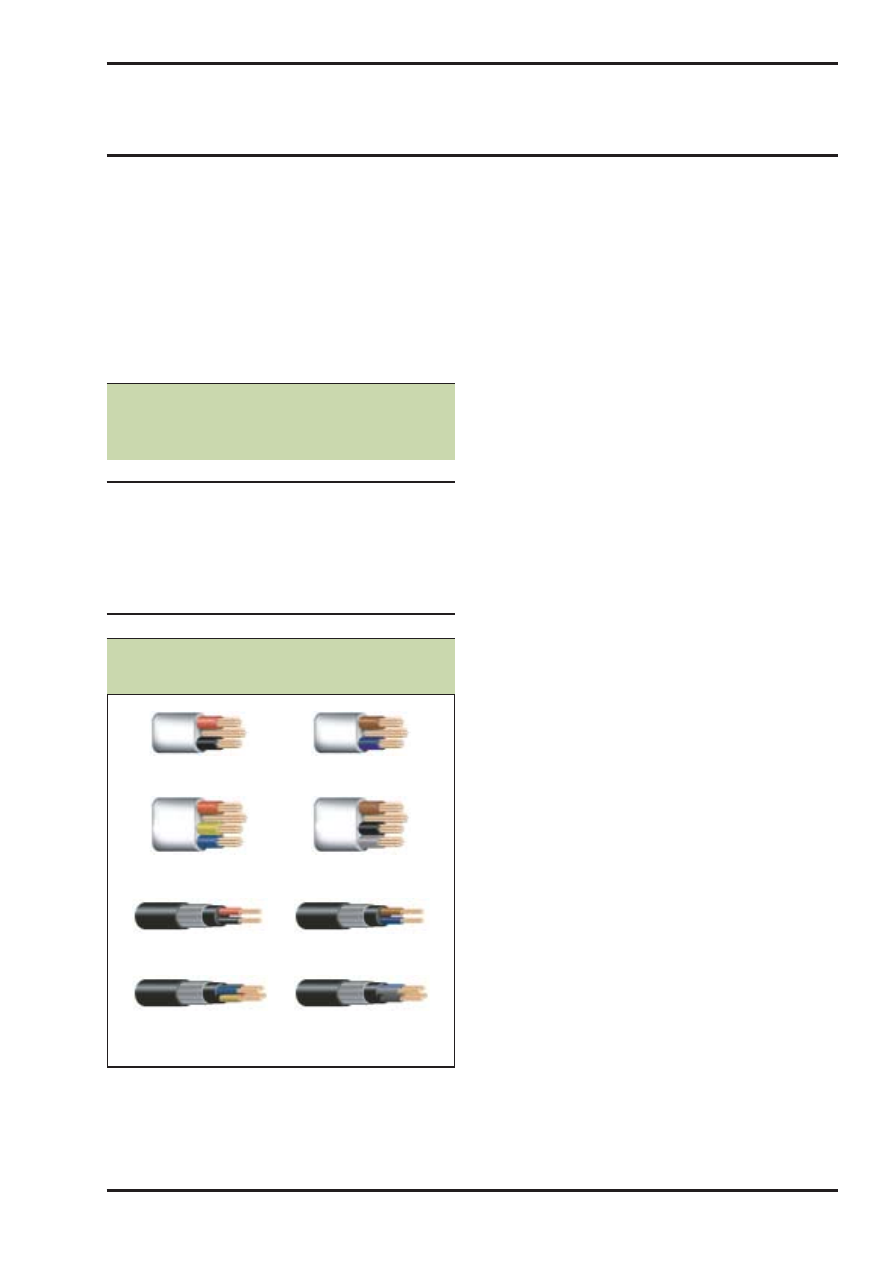
Electrical safety
Approved Document P
39
P
Amendment No 2 to BS 7671: 2001 published
on 31 March 2004 specifies new (harmonised)
cable core colours for all new fixed wiring in
electrical installations in the UK. It includes
guidance for alterations and additions to
installations wired in the old cable colours.
Table D1 below gives the new cable core
colours for ac power circuits. Figure D1 shows
examples of flat and armoured single phase
and 3-phase ac power cables with the old and
the new harmonised colours.
The new (harmonised) colour cables may be
used on site from 31 March 2004. New
installations or alterations to existing
installations may use either new or old colours,
but not both, from 31 March 2004 until 31
March 2006. Only the new colours may be used
after 31 March 2006.
For single phase installations in domestic
premises, the new colours are the same as
those for flexible cables to appliances, namely
green-and-yellow, blue and brown for the
protective, neutral and phase conductors
respectively.
Further information, including cable
identification colours for extra-low voltage and
dc power circuits, is available from the
following sources:
New wiring colours. Leaflet published by the
IEE, 2004. Available for downloading from the
IEE website at www.iee.org/cablecolours.
ECA comprehensive guide to harmonised cable
colours, BS 7671: 2001 Amendment No 2.
Electrical Contractors’ Association, March 2004.
New fixed wiring colours - A practical guide.
National Inspection Council for Electrical
installation Contracting (NICEIC), Spring 2004.
NEW HARMONISED CABLE IDENTIFICATION COLOURS
Appendix D: New harmonised cable
identification colours
Table D1:
Identification of
conductors in ac power
and lighting circuits
Conductor
Colour
Protective conductor
Green-and-yellow
Neutral
Blue
Phase of single phase circuit
Brown
Phase 1 of 3-phase circuit
Brown
Phase 2 of 3-phase circuit
Black
Phase 3 of 3-phase circuit
Grey
Figure D1: Examples of cables with old
and new colours
Old New

Approved Document P
Electrical safety
40
P
IEE On-Site Guide (BS 7671, 16th Edition
Wiring Regulations). The Institution of Electrical
Engineers. ISBN 0-85296-987-2, 2002
IEE Guidance Note 1: Selection and erection of
equipment. 4th Edition. The Institution of
Electrical Engineers.
ISBN 0-85296-989-9, 2002
IEE Guidance Note 2: Isolation and switching:
4th Edition. The Institution of Electrical
Engineers. ISBN 0-85296-990-2, 2002
IEE Guidance Note 3: Inspection and testing.
4th Edition. The Institution of Electrical
Engineers. ISBN 0-85296-991-0, 2002
IEE Guidance Note 4: Protection against fire.
4th Edition. The Institution of Electrical
Engineers. ISBN 0-85296-992-9, 2003
IEE Guidance Note 5: Protection against
electric shock. 4th Edition. The Institution of
Electrical Engineers.
ISBN 0-85296-993-7, 2002
IEE Guidance Note 6: Protection against
overcurrent. 4th Edition. The Institution of
Electrical Engineers.
ISBN 0-85296-994-5, 2003
IEE Guidance Note 7: Special locations. 2nd
Edition (incorporating the 1st and 2nd
amendments). The Institution of Electrical
Engineers. ISBN 0-85296-995-3, 2003
New wiring colours. Leaflet published by the
IEE, 2004. Available for downloading from the
IEE website at www.iee.org/cablecolours
ECA comprehensive guide to harmonised cable
colours, BS 7671: 2001 Amendment No 2.
Electrical Contractors’ Association,
March 2004
New fixed wiring colours - A practical guide.
National Inspection Council for Electrical
installation Contracting (NICEIC), Spring 2004
The Building Regs but not Part P. Article
published by the IEE, Spring 2004. Available for
downloading from the IEE website at
http://www.iee.org/Publish/WireRegs/
IEE_Building_Regs.pdf
Electrical Installers’ Guide to the Building
Regulations. NICEIC and ECA, August 2004.
Available from www.niceic.org.uk and
www.eca.co.uk
Other publications referred to
BS 7671: 2001 (incorporating Amendments
No1: 2002 and No 2: 2004). Requirements for
Electrical Installations (IEE Wiring Regulations
16th Edition). The Institution of Electrical
Engineers. ISBN 0-86341-373-0, 2004
Standards referred to
REFERENCES AND OTHER SOURCES OF INFORMATION

The following documents have been approved
and issued by the Secretary of State for the
purpose of providing practical guidance with
respect to the requirements of the Building
Regulations 2000 (as amended)
Approved Document A - Structure: 1992
Edition, fourth impression (with amendments)
1994, further amended 2000
Approved Document B - Fire safety:
2000 Edition, amended 2000 and 2002
Approved Document C - Site preparation and
resistance to moisture: 1992 Edition, second
impression (with amendments) 1992, further
amended 2000
Approved Document D - Toxic substances:
1985 Edition, amended 1992, further amended
2000
Approved Document E - Resistance to the
passage of sound: 2003 Edition
Approved Document F - Ventilation:
1995 Edition, amended 2000
Approved Document G - Hygiene:
1992 Edition, second impression (with
amendments) 1992, further amended 2000
Approved Document H - Drainage and waste
disposal: 2002 Edition
Approved Document J - Combustion
appliances and fuel storage systems:
2002 Edition
Approved Document K - Protection from
falling, collision and impact: 1998 Edition,
amended 2000
Approved Document L1 - Conservation of
fuel and power in dwellings: 2002 Edition
Approved Document L2 - Conservation of
fuel and power in buildings other than
dwellings: 2002 Edition
Approved Document M - Access and
facilities for disabled people: 2004 Edition
Approved Document N - Glazing - safety in
relation to impact, opening and cleaning:
1998 Edition, amended 2000
Approved Document P - Electrical safety:
2004 Edition
Approved Document to support regulation
7 - materials and workmanship: 1999 Edition,
amended 2000
Electrical safety
Approved Document P
Printed in the United Kingdom for The Stationery Office
169827 C200 07/04
Approved Document P
Electrical safety
P
APPROVED DOCUMENTS
Approved Documents
Part P build regs Cover jan 2k5 5/1/05 14:20pm Page 3
P
The Building Regulations 2000
Electrical safety
APPROVED DOCUMENT
P1
Design, installation, inspection and testing
P2
Provision of information
Building Regulations 2000
APPROVED
DOCUMENT
P
Electrical Safety
Coming into effect 1 January 2005
© Crown Copyright 2004.
Copyright in the typographical arrangement and design rests with the Crown.
Published for the Office of the Deputy Prime Minister, under licence from the Controller of Her Majesty’s Stationery Office.
This publication, excluding logos, may be reproduced free of charge in any format or medium for research, private study or for internal circulation
within an organisation.This is subject to it being reproduced accurately and not used in a misleading context.The material must be acknowledged
as Crown copyright and the title of the publication specified.
For any other use of this material please write to The HMSO Licensing Division, HMSO, St Clements House, 2–16 Colegate, Norwich NR3 1BQ.
Fax: 01603 723000 or email: licensing@cabinet-office.x.gsi.gov.uk
£15
www.tso.co.uk
Published by TSO (The Stationery Office) and available from:
Online
www.tso.co.uk/bookshop
Mail,Telephone, Fax & E-mail
TSO
PO Box 29, Norwich NR3 1GN
Telephone orders/General enquiries: 0870 600 5522
Fax orders: 0870 600 5533
E-mail: book.orders@tso.co.uk
Textphone: 0870 240 3701
TSO Shops
123 Kingsway, London WC2B 6PQ
020 7242 6393 Fax 020 7242 6394
68–69 Bull Street, Birmingham B4 6AD
0121 236 9696 Fax 0121 236 9699
9–21 Princess Street, Manchester M60 8AS
0161 834 7201 Fax 0161 833 0634
16 Arthur Street, Belfast BT1 4GD
028 9023 8451 Fax 028 9023 5401
18–19, High Street, Cardiff CF10 1PT
029 2039 5548 Fax 029 2038 4347
71 Lothian Road, Edinburgh EH3 9AZ
0870 606 5566 Fax 0870 606 5588
TSO Accredited Agents
(see Yellow Pages)
and through good booksellers
Part P build regs Cover jan 2k5 5/1/05 14:20pm Page 1
Document Outline
- Approved Document Part P
- Contents
- Use of guidance
- The Requirements
- Section 0: GENERAL GUIDANCE
- Section 1: DESIGN, INSTALLATION, INSPECTION AND TESTING
- Section 2: EXTENSIONS, MATERIAL ALTERATIONS AND MATERIAL CHANGES OF USE
- Section 3: INFORMATION ABOUT OTHER LEGISLATION
- Appendix A: Examples of electrical installation diagrams
- Appendix B: Copies of BS 7671 and IEE model forms
- Appendix C: Older practice that can be encountered in alteration work
- Appendix D: New harmonised cable identification colours
- Standards referred to
- Other publications referred to
- Approved Documents
- Contents
Wyszukiwarka
Podobne podstrony:
08 Bezpieczeństwo elektrowni jądrowych
Electrical Safety Student Manual
PG Bezpieczeństwo elektrowni jądrowych Wprowadzenie do niezawodności i bezpieczeństwa
ELECTRICAL SAFETY
ściągi z bhp i bezpieczeństwa, Elektrotechnika I stopień PWSZ Leszno, SEMESTR II, coś tam ze szkoły
Bezpieczne elektryczne układy sterujące
Bezpieczenstwo elektryczne zagadnienia wyklad
kolorowanka bezpieczna elektrycznosc
bezpieczniki, Elektrotechnika-materiały do szkoły, Energoelektronika
Wnioski i uwagi-bezpieczniki, Elektroenergetyka
Bezpieczenstwo elektryczne lab3
bezpieczeństwo elektryczne kopia do foliogramów
termin II 2005 2, Notatki, Elektronika AGH III rok, [STUDIA] rok 3, Sieci, Egzamin - sieci
termin II 2005, Notatki, Elektronika AGH III rok, [STUDIA] rok 3, Sieci, Egzamin - sieci
Bezpiecze�stwo elektryczne
bezpieczeństwo elektryczne
bezpieczniki, Elektryka w budownictwie
Bezpieczeństwo elektryczne
więcej podobnych podstron