
Table of Contents
Subject
Page
N62B48O1 . . . . . . . . . . . . . . . . . . . . . . . . . . . . . . . . . . . . . . . . . . . . . . . . . . . . . . . . . . . . . . . . . . . . . . . . . . . . . . . . . . . . . . . . . . . . .6
New Belt Drive . . . . . . . . . . . . . . . . . . . . . . . . . . . . . . . . . . . . . . . . . . . . . . . . . . . . . . . . . . . . . . . . . . . . . . . . . . . . . . . . . . . . . . . . . .7
Air Intake and Filter . . . . . . . . . . . . . . . . . . . . . . . . . . . . . . . . . . . . . . . . . . . . . . . . . . . . . . . . . . . . . . . . . . . . . . . . . . . . . . . . . . . . . . .7
E70 Fuel Tank . . . . . . . . . . . . . . . . . . . . . . . . . . . . . . . . . . . . . . . . . . . . . . . . . . . . . . . . . . . . . . . . . . . . . . . . . . . . . . . . . . . . . . . . . . . .10
Transfer Case ATC 700 . . . . . . . . . . . . . . . . . . . . . . . . . . . . . . . . . . . . . . . . . . . . . . . . . . . . . . . . . . . . . . . . . . . . . . . . . . . . . . . . . . . .12
E70 Powertrain Workbook
Initial Print Date: 12/06
Revision Date:

Table of Contents
Subject
Page
System Pressure in Reverse Gear . . . . . . . . . . . . . . . . . . . . . . . . . . . . . . . . . . . . . . . . . . . . . . . . . . . . . . . . . . . . . . . . . . . . .18
Clutch Valves . . . . . . . . . . . . . . . . . . . . . . . . . . . . . . . . . . . . . . . . . . . . . . . . . . . . . . . . . . . . . . . . . . . . . . . . . . . . . . . . . . . . . . .18
Solenoid Valves (MV) . . . . . . . . . . . . . . . . . . . . . . . . . . . . . . . . . . . . . . . . . . . . . . . . . . . . . . . . . . . . . . . . . . . . . . . . . . . . . . . . .19
Electronic Pressure Control Valves (EDS) . . . . . . . . . . . . . . . . . . . . . . . . . . . . . . . . . . . . . . . . . . . . . . . . . . . . . . . . . . . . . . .19
Target gear allocation dependent on accelerator pedal gradient . . . . . . . . . . . . . . . . . . . . . . . . . . . . . . . . . . . . . . . . . . . . . .20
Shift Speed Characteristics . . . . . . . . . . . . . . . . . . . . . . . . . . . . . . . . . . . . . . . . . . . . . . . . . . . . . . . . . . . . . . . . . . . . . . . . . . . . . .20
Torque Intervention . . . . . . . . . . . . . . . . . . . . . . . . . . . . . . . . . . . . . . . . . . . . . . . . . . . . . . . . . . . . . . . . . . . . . . . . . . . . . . . . . . . . .20
LIN-bus Module . . . . . . . . . . . . . . . . . . . . . . . . . . . . . . . . . . . . . . . . . . . . . . . . . . . . . . . . . . . . . . . . . . . . . . . . . . . . . . . . . . . . . . . .20
Gear Selector Lever (GWS) . . . . . . . . . . . . . . . . . . . . . . . . . . . . . . . . . . . . . . . . . . . . . . . . . . . . . . . . . . . . . . . . . . . . . . . . . . . . . .21
Operation and Functions . . . . . . . . . . . . . . . . . . . . . . . . . . . . . . . . . . . . . . . . . . . . . . . . . . . . . . . . . . . . . . . . . . . . . . . . . . . . .21
Haptic Locks . . . . . . . . . . . . . . . . . . . . . . . . . . . . . . . . . . . . . . . . . . . . . . . . . . . . . . . . . . . . . . . . . . . . . . . . . . . . . . . . . . . . . . . .21
Manual Gate, Sport Program (M/S) . . . . . . . . . . . . . . . . . . . . . . . . . . . . . . . . . . . . . . . . . . . . . . . . . . . . . . . . . . . . . . . . . . . .22
Parking Lock "P" . . . . . . . . . . . . . . . . . . . . . . . . . . . . . . . . . . . . . . . . . . . . . . . . . . . . . . . . . . . . . . . . . . . . . . . . . . . . . . . . . . . .22
Automatic Downshift from "M/S" . . . . . . . . . . . . . . . . . . . . . . . . . . . . . . . . . . . . . . . . . . . . . . . . . . . . . . . . . . . . . . . . . . . . . .22
Flashing of a Position LED . . . . . . . . . . . . . . . . . . . . . . . . . . . . . . . . . . . . . . . . . . . . . . . . . . . . . . . . . . . . . . . . . . . . . . . . . . . .23
Indicator Flashing Through Diagnosis . . . . . . . . . . . . . . . . . . . . . . . . . . . . . . . . . . . . . . . . . . . . . . . . . . . . . . . . . . . . . . . . . .23
Secure Indicator Status . . . . . . . . . . . . . . . . . . . . . . . . . . . . . . . . . . . . . . . . . . . . . . . . . . . . . . . . . . . . . . . . . . . . . . . . . . . . . .24

Table of Contents
Subject
Page
Evaluating the P-button . . . . . . . . . . . . . . . . . . . . . . . . . . . . . . . . . . . . . . . . . . . . . . . . . . . . . . . . . . . . . . . . . . . . . . . . . . . . . .24
Evaluating the Unlock Button . . . . . . . . . . . . . . . . . . . . . . . . . . . . . . . . . . . . . . . . . . . . . . . . . . . . . . . . . . . . . . . . . . . . . . . . .25

4
E70 Powertrain Workbook
Powertrain
Model: E70
Production: From Start of Production
After completion of this module you will be able to:
• Describe the new engines used in the E70
• Understand the changes to the powertrain on the E70
• Understand GWS shifter operation on the E70
E70 Powertrain Workbook
5
E70 Powertrain
6
E70 Powertrain Workbook
E70 Engines
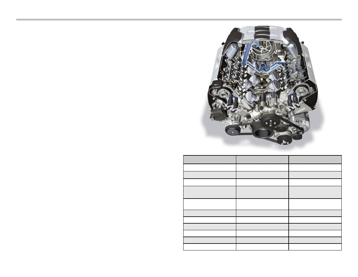
N62B48O1
From the start of production, the X5 4.8is will receive the N62TU
engine as introduced on the E65 in 2005. This engine will be
referred to as the N62B48O1 engine to be consistent with the new
engine code designations.
The N62B48O1 features the following:
• New air cleaner and air intake system
• Modified belt drive
• Oil pan (for installation into E70)
The engine management for the new engine is the ME9.2.3 system
which is a further variant of the ME9.2.2 . The processor speed has
been increased to 66 Mhz to cope with the enhanced capabilities of
the engine and chassis systems in the E70.
Most of the engine systems and mechanical components are the
same as on the previous N62TU from 2005. With the exception of
the items outlined above, the engine is mechanically the same as
it’s predecessor.
As compared to the N62B44 in the E53, the horsepower and
torque have been increased. However, the N62B48O1 complies
with the ULEV II requirements.
The exhaust system has been modified to meet ULEV standards.
The catalyst design allows the elimination of the secondary air sys-
tem.
On of the most notable changes to the physical appearance of the
engine is the air intake system and air cleaner assembly. This
design allows the new N62 to meet acoustic goals as well as the
necessary requirements for pedestrian protection.
Specification
N62B44 (E53)
N62B48O1 (E70)
Engine type
V-8 90 degrees
V-8 90 degrees
Displacement (cm3)
4398
4799
Stroke/bore (mm)
82.7/92
88.3/93
Power output (kW/bhp)
at engine speed (rpm)
235/320
6100
261/350
6300
Torque (Nm)
at engine speed (rpm)
440
3600
475
3500
Compression ratio
10.0
10.5
Valves/cylinder
4
4
Fuel type (RON)
98
98
Firing order
1-5-4-8-6-3-7-2
1-5-4-8-6-3-7-2
Engine management
ME9.2 with VVT
ME9.2.3 with VVT
Emission standard
LEV
ULEV II
E70 Powertrain Workbook
7
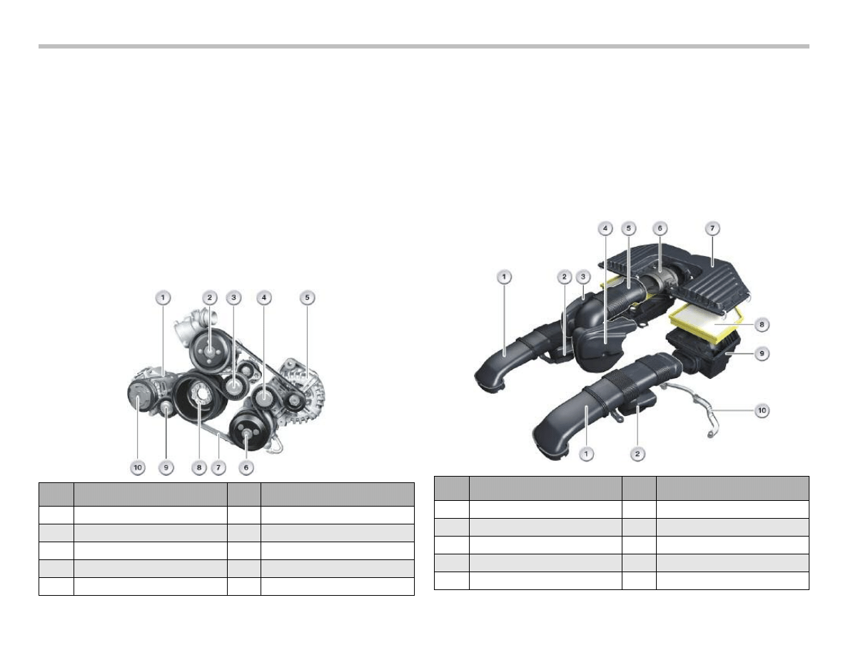
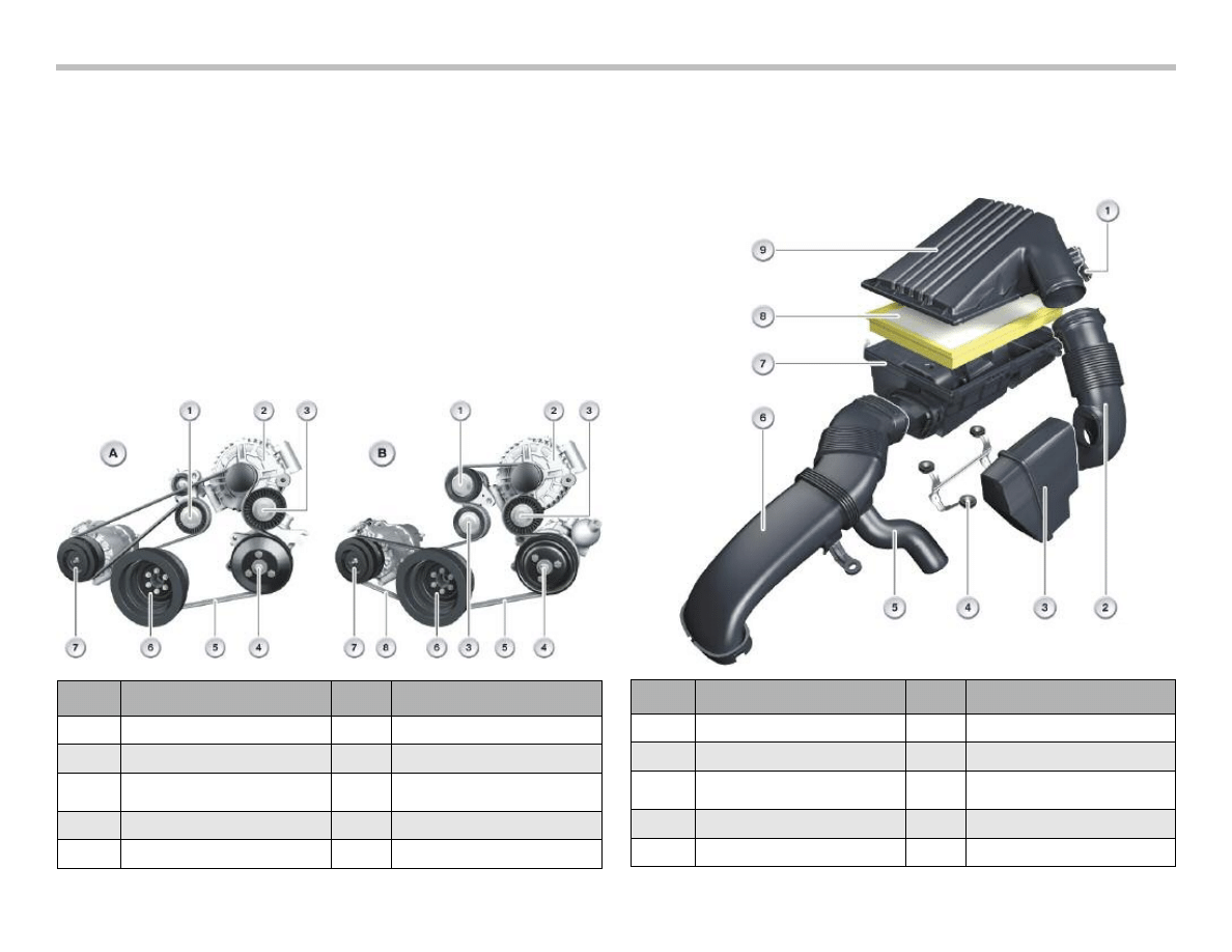
New Belt Drive
The belt drive on the 4.8 engine has been modified for use on the
E70. The alternator and A/C compressor have been relocated for
space reasons.
The belt drive is a double system as standard. The main belt drive
is a ribbed seven groove belt which includes the power steering
pump, alternator and coolant pump.
The A/C compressor is driven by an ELAST drive belt. However, a
new feature is a linear tensioner which eliminates the need for a
special tool for removal or installation.
Be aware that the A/C compressor and alternator have a new
mounting technique which has a threaded insert to align the belt
drive properly. It is imperative to follow the removal instructions.
Air Intake and Filter
The new air filter and intake system has been designed to allow
increased airflow and improve engine acoustics. It is mounted on
the engine rather than on the inner fender or front support as on
past designs.
The intake system features a series of filtered and un-filtered air
resonators to accomplish these goals.
The new design also allows compatibility with the pedestrian
protection features on the E70.
Index
Explanation
Index
Explanation
1
ELAST drive belt for AC comp
6
Power steering pump
2
Coolant pump
7
Ribbed V-belt
3
Tensioning pulley
8
Torsional vibration damper
4
Deflection pulley
9
Linear tensioner
5
Alternator
10
AC compressor
Index
Explanation
Index
Explanation
1
Unfiltered air pipe
6
HFM
2
Unfiltered air resonator
7
Intake silencer cover
3
Filtered air resonator
8
Air cleaner
4
Double-chamber filtered resonator
9
Intake silencer
5
Unfiltered air pipe
10
Bracket
8
E70 Powertrain Workbook
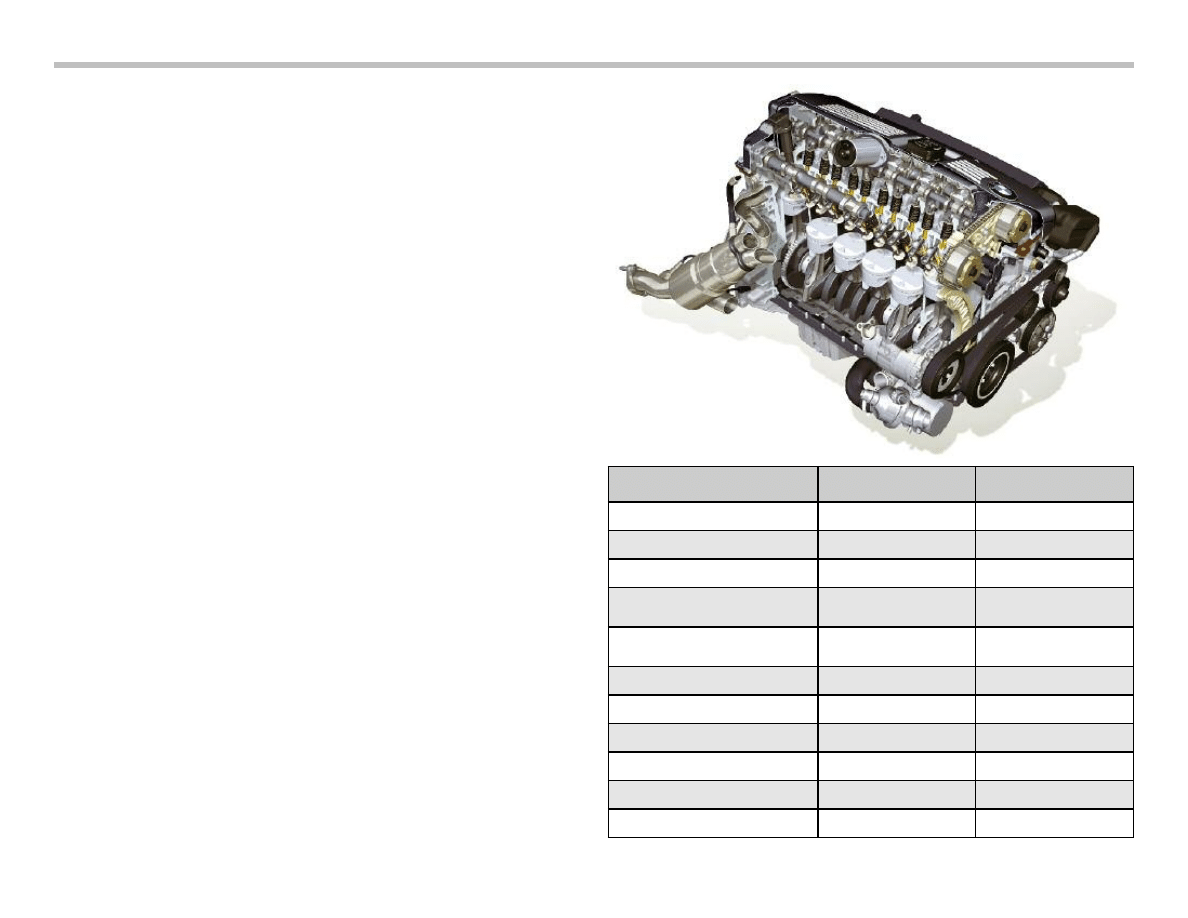
N52B30O1
For the 6-cylinder version of the E70, the new N52KP engine will
be used. This new N52KP is the upper output version as intro-
duced on the E83LCI with some minor changes.
Many of the mechanical changes are the same as on the N52KP
engines in order models (E83/E9X etc).
The N52B30O1 features:
• Plastic cylinder head cover
• Modified oil pan for installation into E70
• Crankshaft has higher degree of balance
(to reduce load on drivetrain)
• New Torsional vibration damper
• Modified belt drive
• 6 mm exhaust valves
• Lightweight “hydroformed” camshafts
The engine management system is the MSV80 system which
includes improvements over the MSV70 system. These items
include:
• Digital HFM
• New throttle valve with magneto resistive feedback
• 180 amp alternator (Bosch or Valeo)
• Oil level/quality sensor (QLT)
The MSV80 engine management complies with the ULEV II
requirements for 2007.
The catalyst system allows for the elimination of the secondary
air pump.
Note: For more detail, see the ST616 training course.
Specification
M54B30 (E53) N52B30O1 (E70)
Engine type
inline 6
inline 6
Displacement (cm3)
2979
2996
Stroke/bore (mm)
89.6/84
88.0/85
Power output (kW/bhp)
at engine speed (rpm)
170/231
5900
163/260
6600
Torque (Nm)
at engine speed (rpm)
300
3500
305
2500
Compression ratio
10.2
10.7
Valves/cylinder
4
4
Fuel type (RON)
98
98
Firing order
1-5-3-6-2-4
1-5-3-6-2-4
Engine management (DME)
MS43
MSV80
Emission standard
LEV
ULEV II
New Belt Drive (N52B30O1)
With regard to the 6-cylinder, there are two possible belt drive
arrangements on the E70.
The single belt drive uses a 6 rib v-belt with a conventional “spring
loaded” belt tensioner.
If the E70 is equipped one of the following options; Active steering,
Adaptive Drive or the 220 Amp Alternator, there is a double belt
drive.
In this case, the A/C compressor is driven separately by a four rib
ELAST drive belt. As opposed to the V-8 engine, this ELAST belt
does not have a linear tensioner and must be installed with the
special tool as one previous applications.
Intake Air Control
As with the V-8 engine option, the 6-cylinder uses an engine
mounted air filter and duct system. This arrangement also achieves
the desired sound quality goals and also meets the necessary
crash optimization requirements for pedestrian protection.
E70 Powertrain Workbook
9
Index
Explanation
Index
Explanation
1
Hot-film air mass meter
6
Unfiltered air pipe
2
Filtered air pipe
7
Intake silencer
3
Double chambered filtered air
resonator
8
Air cleaner
4
Bracket
9
Intake silencer cover
5
Unfiltered air resonator
Index
Explanation
Index
Explanation
A
Basic belt drive
4
Power steering pump
B
Double belt drive
5
Ribbed V-belt
1
Tensioning pulley
6
Torsional vibration damper
2
Alternator
7
A/C compressor
3
Deflection pulley
8
ELAST drive belt for A/C comp
10
E70 Powertrain Workbook
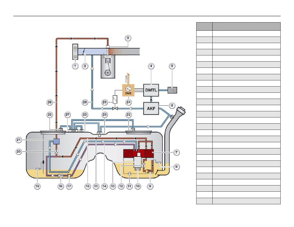
E70 Fuel Tank
Index
Explanation
1
Engine air cleaner
2
intake manifold
3
Fuel injectors
4
DM-TL
5
Dust filter
6
Purge canister
7
Fuel filter
8
Fuel level sensor
9
Suction jet pump
10
Intake mesh filter
11
Initial filling valve
12
Non-return valve
13
Electric fuel pump
14
Compensating line
15
Return line
16
Feed line
17
Suction jet pump
18
Non-return valve
19
Fuel level sensor
20
Non-return valve
21
Pressure regulator
22
Breather valve
23
Refuelling vent valve
24
ECM (DME)
25
Fuel tank vent valve (purge valve)
26
Purge air line
27
Central constant pressure valve (Z-DHV)
28
Feed line to engine
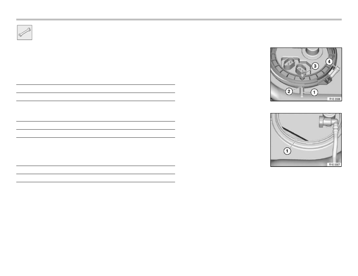
Workshop Exercise - Fuel Tank
Using the fuel tank training aid, remove the service openings
from both sides. Remove the fuel pump and both sending
units.
What’s new about the seals and clamps on the service openings
on the fuel tank?
Why are the seals and clamps a new design?
When installing a new clamp (or clamps) how is proper tightening
torque achieved?
Using the illustration on the page above, compare actual
components to the illustrated ones to gain better understanding
of actual system operation.
Re-install fuel system components into fuel tank and observe
the following:
E70 Powertrain Workbook
11
Installation:
Make sure that service cover is
installed in correct position.
Indentation (2) on clamping ring
must line up with raised section (1)
of tank.
Pin on service cover (3) must line
up with indentation on clamping
ring.
Ensure correct positioning of seal.
Always replace seal and clamp in
field service situations.
12
E70 Powertrain Workbook
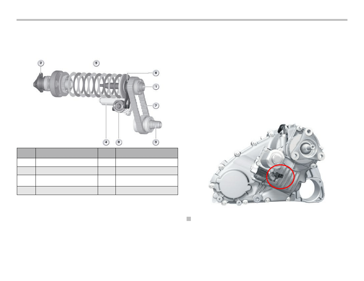
Transfer Case ATC 700
The ATC 700 transfer case is a further development of the ATC500
transfer case known from the E53. The power transfer takes place
via a chain drive and multi-disc clutch.
As compared to the ATC 500, there are only minor changes:
• Installation position of coding resistor
• Optimized lifetime gear oil
• New ventilation system
• Transfer case control unit (VGSG)
Coding Resistor
The locking power characteristic of the multi-disc clutch can vary
slightly due to the mechanical tolerances in the production process.
After measuring the actual locking power on the clutch test rig, a
resistor is fitted to the actuator motor with its value representing a
reference regarding the progression of the locking power.
Every time the engine is started, the transfer box control unit
measures the resistance and correspondingly selects the optimum
characteristic map for the installed transfer box.
To facilitate accessibility, the coding resistor is no longer fitted on
the casing of the worm drive but rather on the casing of the transfer
box.
Transfer Box Control Unit
The transfer box control unit is known from the E60 and E90 all-
wheel drive models. It has a new housing that is not water-tight. It
is arranged under the luggage compartment floor on the left next to
the battery.
Index
Explanation
Index
Explanation
1
Input from automatic gearbox
5
Multi-disc clutch
2
Output to rear axle
6
Actuator lever with ball ramp
3
Output to front axle
7
Chain drive
4
Actuator motor
8
Control wheel

E70 Powertrain Workbook
13
NOTES
PAGE
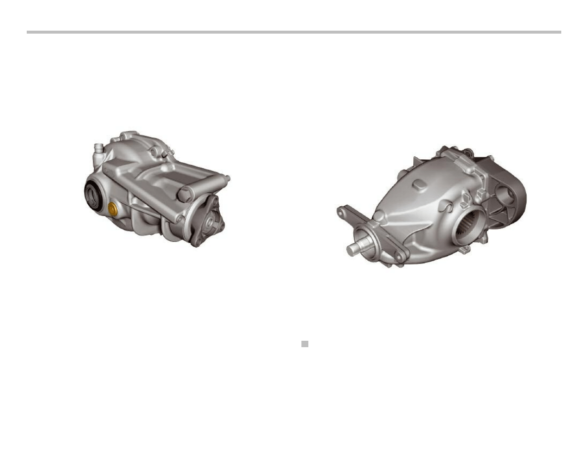
Front and Rear Differential
Front Axle Gearbox VAG180A
The front axle gearbox is a new design with an aluminum casing.
As before, it is centered and mounted as part of the oil pan. In
terms of function, the front axle gearbox remains the same as that
in the E53 predecessor.
Two different drive flange variants are used for 6-cylinder and
8-cylinder engines.
• In connection with the N52B30O1 engine, the propeller shaft
is connected by means of a flexible coupling to the front axle
gearbox.
• In connection with the N62B48O1 engine, the propeller shaft
is pivoted further downward due to the catalytic converters.
The front axle gearbox is adapted accordingly. For this reason, a
universal joint is used as the drive flange in this case. The oil filler
and drain plug is located in the same position as on the E53.
Final Drive Unit HAG188K/188L
The final drive unit (rear axle differential) HAG188K is already
known from the previous model series. The HAG188L represents
a further development that is fitted on the E70 with N62B48O1
engine.
The output shafts are now also fitted in a plug-on arrangement to
the final drive unit as known from the front axle gearbox of the E53.
Since there is now no flange for the output shafts, the final drive
unit is supplied without an oil fill for replacement purposes.
The propeller shaft is also fitted in a plug-on arrangement to the
final drive unit and therefore also has no drive flange. Instead, the
SAE gearing of the drive pinion extend out of the casing of the final
drive unit. The propeller shaft is fitted onto the spline.
HAG188L
Angular contact ball bearings are used in the HAG188L instead of
the taper roller bearings in the HAG188K. The ball bearings greatly
reduce friction losses. In addition to contributing to lowering fuel
consumption, this measure also reduces power loss in the thermal
balance of the axle drive.
14
E70 Powertrain Workbook
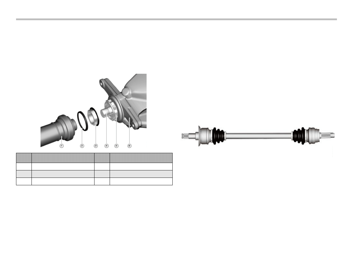
`Propeller Shaft and Output Shafts
Propeller Shafts
A new connection arrangement of the rear propeller shaft to the
final drive unit (rear axle differential) is used on the E70.
The constant velocity joint of the propeller shaft is now bolted to
the flange of the final drive unit but rather it is fitted onto the unit.
This arrangement offers various advantages:
• Reduced overall size
• Improved balance characteristics
• Shorter assembly time
• Quieter running
• Higher torsional rigidity
The rear propeller shaft in the E70 is fitted onto the final drive unit.
This arrangement provides many advantages regarding function
and assembly.
Output Shafts
The output shafts are also fitted in a plug-on arrangement to the
final drive unit as already known from the front axle gearbox.
The rear output shafts are now fitted in a plug-on arrangement to
the final drive unit as already known from the front output shafts.
Currently, the two CV boots (gaiters) on the constant velocity joints
cannot be replaced.
The housings of the constant velocity joints for the front and rear
output shafts are no longer powder-coated but now have a bright
finish.
E70 Powertrain Workbook
15
Index
Explanation
Index
Explanation
1
Propeller shaft
4
Drive pinion
2
Retaining clip
5
Flange nut
3
Nut
6
Casing of final drive unit
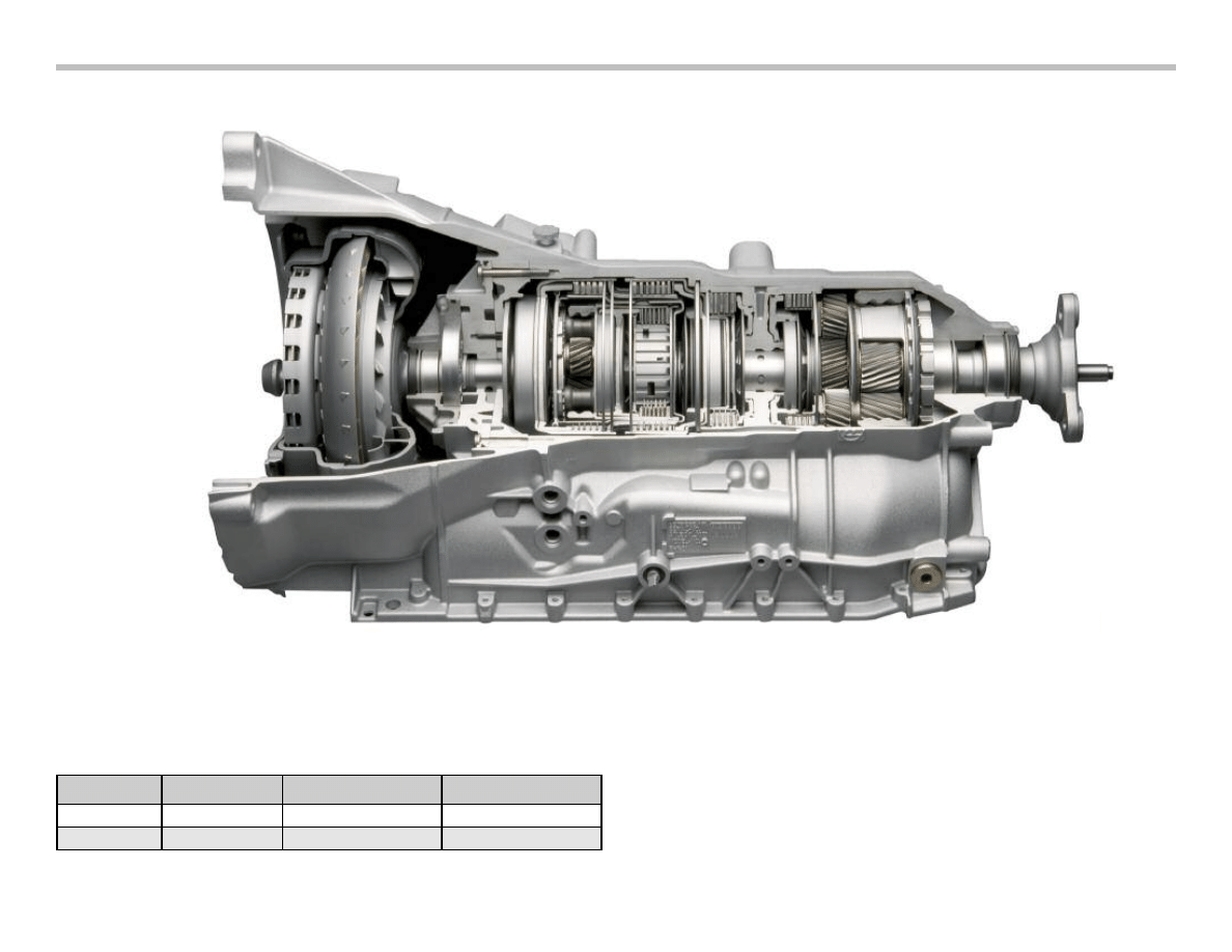
Automatic Transmission (GA6HPTU)
There are 2 new transmission variants for the X5. The new “TU”
version of the already proven 6HP19/26Z has been improved for
use in new vehicles including the X5.
The 6HP19 is used in the E70 X5 3.0, while the 6HP26 can be
found in the 4.8 version.
The automatic gearbox GA6HPTU for the E70 has been
re-engineered in terms of the following points:
• Torque converter with turbine-torsion damper
• Clutch E
• Adapted electronic transmission control (EGS)
• Faster hydraulics through new pressure regulator
• Electric gearshift
16
E70 Powertrain Workbook
Vehicle
Engine
Transmission
Torque Cap.
E70 X5 3.0
N52B30O1
GA6HP19TU
400 Nm
E70 X5 4.8
N62B48O1
GA6HP26TU
650 Nm
Torque Converter
A new torque converter is used in the GA6HPTU gearbox. This
torque converter contains an effective torsion damper system
known as the turbine-torsion damper (TTD).
This is a classic torsion damper, in which the primary side (engine
side) is fixed to the turbine wheel of the torque converter.
This arrangement brings about an increase in the flywheel mass on
the primary side thus distinctly improving the damping properties.
With the converter lockup clutch disengaged, i.e. in converter
mode, the power flow from the turbine wheel does not take place in
the usual manner to the transmission input shaft.
The turbine wheel transmits the power to the primary side of the
torsion damper.
The secondary side of the turbine-torsion damper is connected to
the input shaft of the gearbox. Since the converter transmits no
vibrations, the torsion damper need not perform any damping work.
In this case it functions virtually as a rigid transmission element.
When the converter lockup clutch is engaged, the power is trans-
mitted directly from the clutch to the primary side of the turbine tor-
sion damper. Due to the rigid connection to the turbine wheel of
the torque converter, the flywheel mass is increased on the primary
side.
The power is transmitted via the turbine-torsion damper to the
input shaft of the gearbox. Torsional vibration is filtered out very
effectively.
With this system, it is possible to engage (close) the converter lock-
up clutch much earlier without having to take any deterioration in
comfort into account. This arrangement directly connects the
gearbox to the engine, resulting in a boost in dynamics as well as a
reduction in fuel consumption and exhaust emissions.
Converter Lockup Clutch Connection Stages
The ability of the new torque converter to dampen torsional vibra-
tion with the turbine torsion damper is used to keep the converter
lockup clutch closed as often as possible.
A general statement as to under what conditions the converter
lockup clutch is disengaged (open) or engaged (closed) can still
not be made as this depends on very many factors.
• Load choice signal (accelerator pedal position)
• Engine load status
• Vehicle speed
• Transmission fluid temperature
• Selected gearshift program
E70 Powertrain Workbook
17

Casing and Intermediate Plate
The casing and the intermediate plate of the GA6HPTU gearbox
have been adapted to the new hydraulic unit and the resulting
channel arrangement.
The GA6HPTU gearbox is a reengineered version of the 6-speed
automatic gearbox that was introduced in the E65 and since then
used in all model series.
The modifications are specifically targeted at achieving higher
dynamics, lower fuel consumption and reduced pollutant emis-
sions.
Clutches
The clutch E has been reworked. The clutch E is a drive clutch that
connects the ring gear of the single planetary gear train with the
long planet gear of the double planetary gear train.
It is closed in fourth, fifth and sixth gear. The lining of clutch E is
made from a new material that offers greater stability in terms of
vibration and squeaking.
Electronic-hydraulic Control
The electronic-hydraulic control installed in the GA6HP19/26TU
has been optimized in the following areas with regard to faster
gearshift operations and higher efficiency.
• Torque converter control
• Cooling oil flow
• System pressure in "R"
• Clutch valves
• Electronic pressure control valves
The electronic-hydraulic control now has only two solenoid valves
but seven electronic pressure control valves.
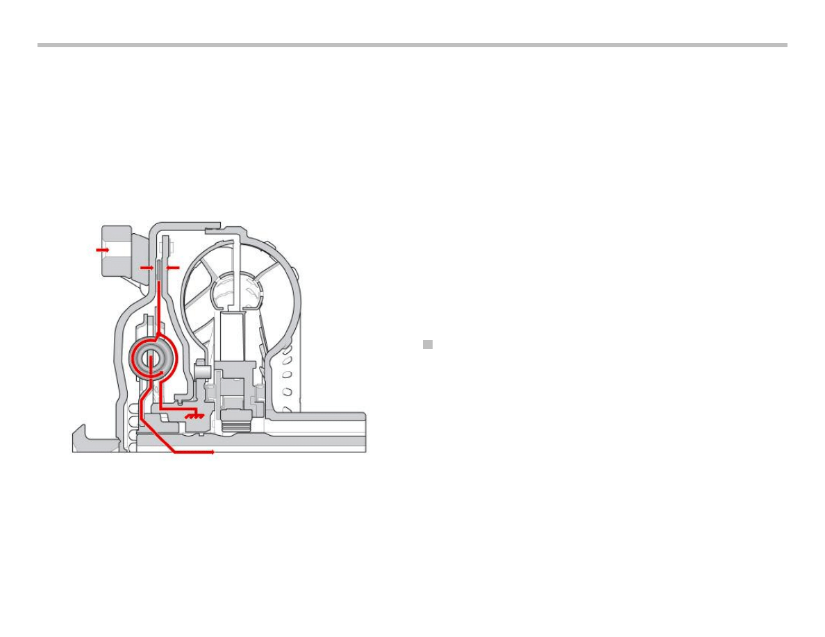
Torque Converter Control
The torque converter control including the converter lockup clutch
has undergone distinct improvements with regard to the control
capabilities under all conditions.
It is equipped with a new pressure regulator. Raised converter
pressure (increased from approx. 0.5 bar to 1 bar at the low end)
ensures faster control of the converter lockup clutch particularly at
low temperatures.
The oil feed comes from the primary connection of the main
pressure control valve, thus improving control at low speeds.
The converter lockup clutch is now engaged with a backpressure
in order to proportionate more effectively.
Variable Cooling Oil Flow
The flow of cooling oil is variable in order to reduce power losses.
No cooling is required for the clutch faces when the converter lock-
up clutch is engaged (closed). The flow of cooling oil can be
reduced in this state thus also reducing the pump power. The flow
of cooling oil is controlled by the main pressure and can vary
between 10 l/min and 15 l/min.
System Pressure in Reverse Gear
The system pressure that is applied in reverse gear has been
increased from 15 bar to 16 bar. This change caters for the higher
torque and the higher possible total weight. It ensures that clutch
slip is prevented even in extreme situations (e.g. uphill gradient with
trailer).
Clutch Valves
The clutch valves now exhibit a smaller control space. This facili-
tates a more spontaneous response as the time required until the
clutch valve reacts to the control pressure applied by the EDS is
shorter. This results in distinctly shorter gearshift times.
18
E70 Powertrain Workbook
Solenoid Valves (MV)
Two solenoid valves are mounted on the hydraulic selector unit.
These valves are designed as 3/2-way valves, i.e. valves with three
connections and two switch positions.
The solenoid valves are controlled by the electronic transmission
control (EGS) and assume the "opened" or "closed" positions
making it possible to switch over the hydraulic valves.
The two solenoid valves are used for the electronically switched
parking lock. One solenoid valve controls the valve for the parking
lock and the other solenoid valve locks the cylinder for the parking
lock.
Electronic Pressure Control Valves (EDS)
The electronic pressure control valves convert electrical current
into a proportional hydraulic pressure. They are driven by the EGS
and operate the hydraulic valves belonging to the shift elements.
The tasks of the electronic pressure control valves are listed in the
following:
The solenoid valve that the EDS (4) in the predecessor model
assigned to the clutches (D and E) depending on the gear to be
shifted is no longer required.
Instead another electronic pressure control valve is used so that
each clutch is now controlled by its own electronic pressure control
valve. The pressure control valve 7 maintains a constant system
pressure during the gearshift operations, thus making shorter shift
times possible.
Three different electronic pressure control valves (EDS) are now
installed which are all resistant to low temperatures. They enable
stable presentation of the gearshift requirements even at low tem-
peratures and when the transmission fluid is cold:
E70 Powertrain Workbook
19
EDS Valve
Corresponding Shift Element
1
Drive Clutch A
2
Converter lock-up clutch
3
Drive Clutch B
4
Drive Clutch E
5
Brake Clutch C
6
Brake Clutch D
7
System pressure
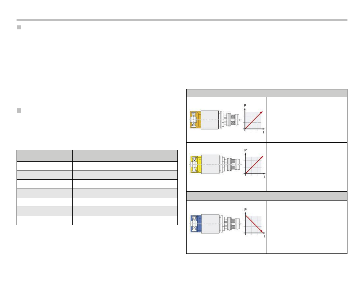
EDS with rising characteristic
Electronic pressure control valves 1, 2:
Orange cap, rising characteristic
Technical data:
•
Pressure range 0 to 4.7 bar
(0 mA = 0 bar, 700 mA = 4.7 bar)
• Supply voltage
12
V
•
Resistance 5.05 Ohm (at 20 °C)
Electronic pressure control valves 4, 5, 6:
Yellow cap, rising characteristic
Technical data:
•
Pressure range 0 to 4.6 bar
(0 mA = 0 bar, 700 mA = 4.6 bar)
•
Supply voltage 12 V
•
Resistance 5.05 Ohm (at 20 °C)
EDS with falling characteristic
Electronic pressure control valves 3, 7:
Blue cap, rising characteristic
Technical data:
•
Pressure range 0 to 4.6 bar
(700 mA = 0 bar, 0 mA = 4.6 bar)
•
Supply voltage 12 V
•
Resistance 5.05 Ohm (at 20 °C)

Target gear allocation dependent on accelerator pedal
gradient
Target gear allocation dependent on the accelerator pedal gradient
replaces the previous target gear allocation system dependent on
the accelerator pedal for the purpose of shifting down while
accelerating.
In the case of accelerator-dependent target gear allocation, based
on the respective downshift characteristic curves, the EGS
determines whether a downshift is necessary while accelerating.
The gearbox shifts down by one gear if the accelerator pedal is
pressed and the first downshift characteristic is reached within a
certain time. If the accelerator pedal is pressed further, the gearbox
shifts down again to the second downshift characteristic and again
to response to the third downshift characteristic.
In the case of accelerator pedal gradient dependent target gear
allocation, the EGS determines the target gear already at the first
downshift characteristic. The accelerator pedal gradient is used for
this purpose. This is the angle the movement of the accelerator
pedal currently described or expressed more simply, the speed at
which the accelerator pedal is depressed.
The target gear which is now determined in connection with the
first downshift characteristic is engaged by a multiple downshift
function. This serves as a boost to overall dynamics as the
corresponding gear is engaged earlier and the interruption in
tractive power is minimized.
Shift Speed Characteristics
The transmission control now has three different shift speed levels
known as quickshift 1, 2 and 3. The higher the level, the faster the
gearshift. The respective shift speed level is selected as a function
of the selected drive program ("D", "S" or "M") and the accelerator
pedal gradient, i.e. as a function of the speed at which the pedal is
depressed.
Torque Intervention
When shifting gear at low load or when coasting, the EGS sends a
so-called torque pulse to the engine management in order to
achieve a torque intervention.
This is negative when upshifting so that the engine speed is
reduced. When downshifting while coasting, the torque interven-
tion is positive in order to boost the engine speed. This torque
intervention facilitates smooth gearshifts without the torque
converter having to intervene in this task.
LIN-bus Module
The EGS now contains a LIN-bus module for communication with
the gear selector lever (GWS).
20
E70 Powertrain Workbook
Gear Selector Lever (GWS)
The automatic gearbox in the E70 is operated by means of an
electric gearshift system. This shifter arrangement is similar to the
E65, however unlike the E65 the E70 is not on the steering column
but rather in the usual position on the center console.
The gear selector lever consists of the selector lever itself with
indicator and the housing with the control unit.
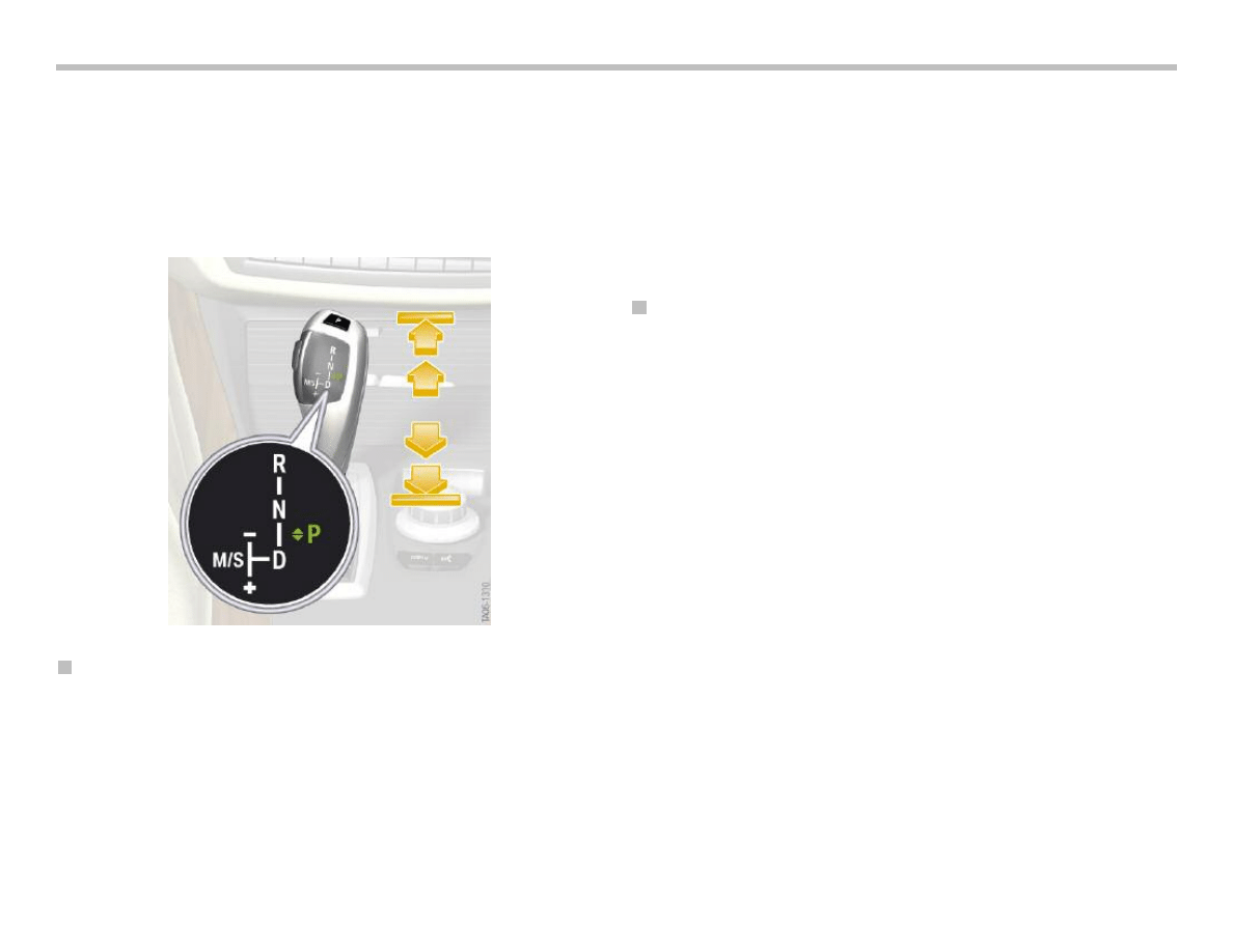
Operation and Functions
The shift pattern is modeled on the conventional BMW automatic
gearbox. It features an automatic gate and a manual gate. Only the
parking lock is not engaged by pushing the selector lever forward
but rather by pressing a button at the top of the selector lever.
The selector lever is monostable in both gates (manual and auto-
matic). This means, after being moved, the selector lever always
returns to its initial position. In the manual gate this is the same as
automatic gearboxes with Steptronic.
In addition to the one-touch function, the selector lever can also be
pushed in the automatic gate. This is comparable to the function
of the direction indicator stalk in the E90.
The drive range is changed by tapping the selector lever. A direct
change from "D" to "R" or vice versa can be achieved by tapping
the selector lever twice or by pushing the lever.
The Unlock button is located on the left-hand side of the selector
lever.
Haptic Locks
Electrically controlled, mechanically actuated locks ensure that the
selector lever can only be pushed in the logically possible direction,
e.g. only forward from "D".
These locks are also used for the shift lock function, i.e. when a
drive range can be engaged only by pressing the unlock button.
The selector lever is not locked if it is necessary to depress the
service brake in order to engage a drive range for example.
Instead, the function is not executed and a message appears in
the on-board monitor indicating: "Press brake to engage gear".
The lock for moving the lever forward differs from the lock for
moving the lever back.
The forward lock is a double lock and can therefore prevent over-
pressing the lever when a flick is possible. In contrast to this, the
backward lock can only completely prevent the movement.
Whenever the selector lever can be pulled back, it can also be
pulled back beyond the stop even if it no longer has a function.
E70 Powertrain Workbook
21
22
E70 Powertrain Workbook
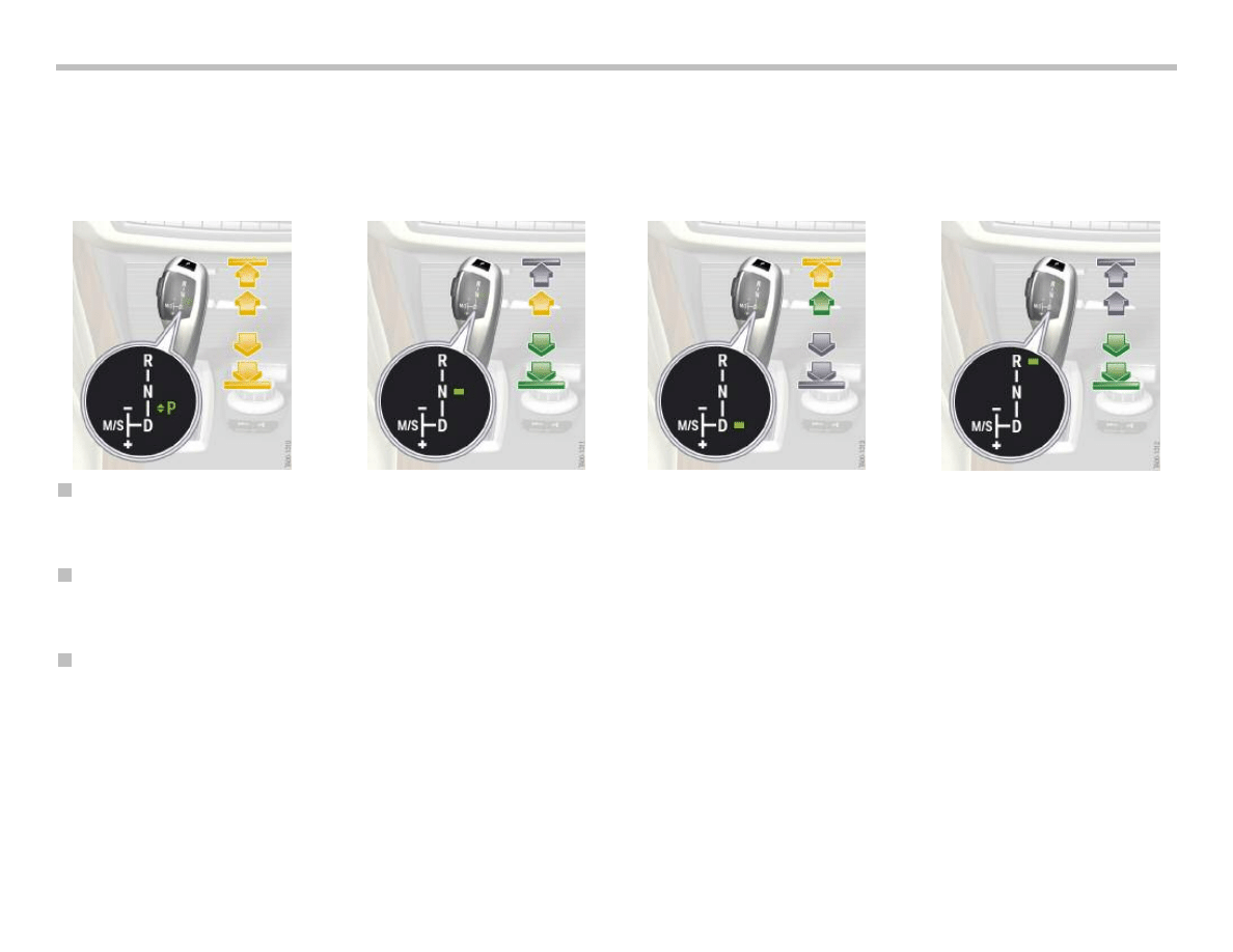
The following graphics illustrate the operating options. The arrows indicate:
• Yellow arrow - Movement possible only with unlock button pressed.
• Grey arrow - Movement not possible.
• Green arrow - Movement possible.
Manual Gate, Sport Program (M/S)
As before, the sport program is engaged by shifting the selector lever to the left. The selector lever locks in this position. The sport
program can only be engaged from "D".
Parking Lock "P"
The parking lock "P" is engaged by pressing the button at the top of the selector lever when the vehicle speed is < 2 km/h. The gearbox
also automatically selects "P" as soon as the engine is turned off and "N" is not engaged.
Automatic Downshift from "M/S"
The automatic downshift function returns the selector lever from the "M/S" gate to the automatic gate. This occurs, for example, when the
EGS signals gearbox position "P" as is the case when the engine is shut down or the "P" button is pressed.
The selector lever remains locked in the "M/S" gate only if "S" or "M" mode is actually active while driving in forward direction or the
automatic downshift is defective or receives no power supply.
5 downshift attempts are executed at intervals of approx. 5 seconds if the selector lever is blocked from the outside, e.g. by an object.
If the downshift cannot be executed, the check control message: "Move selector lever back into automatic gate" appears after two
attempts. A fault code memory entry is generated.

E70 Powertrain Workbook
23
Interface to the EGS
With the aim of increasing availability, the gear selector lever
position is sent via the PT-CAN and LIN-bus. This means, a signal
is still sent to the EGS should the PT-CAN fail. This is not neces-
sary for safety reasons.
Safety is guaranteed by neutrally complementary signals or alive
counters. The gear selector switch (GWS) is woken by a high-level
on the PT-CAN wakeup line. The GSW itself has no active wake-up
capabilities.
Definition of Messages
Communication
The data blocks are sent both event controlled as well as cyclically
on the PT-CAN. They are sent only cyclically on the LIN-bus.
Complementary signals are sent for the purpose of securing the
transmission link.
These signals are compared with the actual signals in the respec-
tive receive control unit. Alive counters serve the purpose of
detecting defects in the transmit control unit. The alive counter in
the respective receive control unit is monitored to establish
whether it remains at a constant value.
A plausibility check between the signals of the PT-CAN transmis-
sion and of the LIN-bus does not take place in the receive control
unit.
Safe Status for Sending
If a GWS-internal plausibility check determines that the position of
the selector lever can be transmitted incorrectly, the system
assumes the safe status for sending the message "Operation of
gear selector lever".
Consequently, all signals of this message are sent invalid on the
PT-CAN and the LIN-bus. If it is not possible to ensure that the
signals can be sent invalid, the sending of these messages is
completely deactivated.
Indicator in the Gear Selector Lever
The task of the indicator in the gear selector lever (GWS) is to
reliably indicate the drive range currently engaged. The indicator
consists of the locator light that represents the shift pattern and the
function lighting. This comprises the various position LEDs that
indicate the drive range currently engaged.
The function lights in the gear selector lever are controlled by the
"Indicate gearbox data" message sent from the EGS. It is neces-
sary to monitor the function lighting. For this purpose, the indica-
tion is read back and compared with the required indication.
The indicator is active as soon as bus communication is active on
the PT-CAN or the LIN-bus.
Flashing of a Position LED
A position LED flashing draws the driver's attention to incorrect
operation. The locator lighting remains constant and does not flash.
The flashing action is triggered by an EGS signal. The frequency is
0.5 Hz.
Indicator Flashing Through Diagnosis
The entire function lighting can be made to flash at a frequency of
1 Hz for approx. 10 seconds by means of a diagnosis job for testing
the indicator.
Interface
From
To
Message
PT-CAN
GWS
EGS
Gear selector lever
operation
PT-CAN
EGS
GWS
Show gearbox data
LIN-bus
GWS
EGS
Gear selector lever
operation
LIN-bus
EGS
GWS
Show gearbox data

Secure Indicator Status
The indicator is a safety-relevant function so that incorrect indica-
tion must be prevented. The system assumes the secure indicator
status if the possibility of an incorrect indication cannot be ruled
out.
The function lighting is switched off for this purpose. The locator
lighting remains switched on.
Transfer to the secure status can be triggered by two events:
• Defective communication on the bus or
• An internal defect in the gear selector lever
The main transmission path to the EGS is the PT-CAN. If the
"Display gearbox data" message is not received correctly on the
PT-CAN, the gear selector lever will change over to the LIN-bus.
If, after changing over to the LIN-bus, a fault is also detected on this
communication path, the system will assume the secure status.
The plausibility check of the LIN-bus is constantly executed in the
background. If it is necessary to change over to the LIN-bus in the
event of a defect, it is possible to switch directly to the secure
indicator state if the system detects beforehand that there are
problems with the communication on the LIN-bus.
A fault code entry is generated in response to changing over to the
secure status due to communication problems. This fault situation
is irreversible. If the "Display gearbox data" message is received
correctly again, the indicator will be activated normally once again
after 2 seconds.
The gear selector lever immediately changes over to the secure
indicator status if the diagnostic function in the gear selector lever
detects an implausibility regarding the indicator.
In this case, a corresponding fault code entry is generated. This
fault case is not reversible until the next time the gear selector lever
assumes sleep mode.
Park and Unlock Button
Evaluating the P-button
The P-button sends the driver's choice to apply the parking lock to
the EGS.
• The P-button is read by means of two contacts in inverse
logic.
• The two contacts are evaluated in separate logic and repre-
sented by the two signals P1 and P2 independent of each
other.
• Before being sent, the P2 signal is inverted in the gear selec-
tor lever.
• The two contacts in the gear selector lever are compared for
diagnostic purposes. A fault code entry is stored if different
contacts are applied for longer than 2 seconds.
• An internal diagnostic function in the gear selector lever
detects a defective contact and enters a corresponding fault
code in the fault code memory.
• The button sticking is detected when at least one contact is
applied for longer than 2 minutes.
• The P1 and P2 signals are sent independent of each other on
the PT-CAN and redundantly on the LIN-bus to the EGS.
• Due to the confirmation tolerances, one signal can be sent as
confirmed before the other.
If the required conditions are met (speed, ...), the EGS will engage
the parking lock when at least one signal (P1 and/or P2) was sent
as confirmed.
24
E70 Powertrain Workbook

Evaluating the Unlock Button
The lock to shift to "R" or out of "P" is released by pressing the
unlock button.
• The unlock button is read by means of two contacts in inverse
logic.
• The two contacts in the gear selector lever are compared for
diagnostic purposes. A fault code entry is stored if different
contacts are applied for longer than 2 seconds.
• An internal diagnostic function in the gear selector lever
detects a defective contact and enters a corresponding fault
code in the fault code memory.
• Before being sent, the P2 signal is inverted in the gear selec-
tor lever.
• The button sticking is detected when at least one contact is
applied for longer than 2 minutes.
• Both signals are sent on the PT-CAN and redundantly on the
LIN-bus to the EGS as soon as a contact is detected as con-
firmed.
Components
Sensors
The selector lever position is detected without contact with the aid
of seven Hall sensors for detecting the selector lever position in the
longitudinal direction of the vehicle as well as four Hall sensors for
detecting the selector lever position in the transverse direction of
the vehicle.
In the event of one individual sensor failing, the software in the gear
selector lever is still capable of calculating the correct position of
the selector lever.
Actuators
Three actuators are used. A motor with subsequently connected
gear mechanism is used for shifting out of the "M/S" gate and for
the lock (inhibit) to "M/S".
A bi-directional spring-centered double magnet is used for the
inhibit in "R" direction. A single magnet with spring reset is used
for the inhibit in "D" direction.
The actuators do not inhibit the shift to "R" and "D" in the case of
fault or if no power is applied.
E70 Powertrain Workbook
25
26
E70 Powertrain Workbook
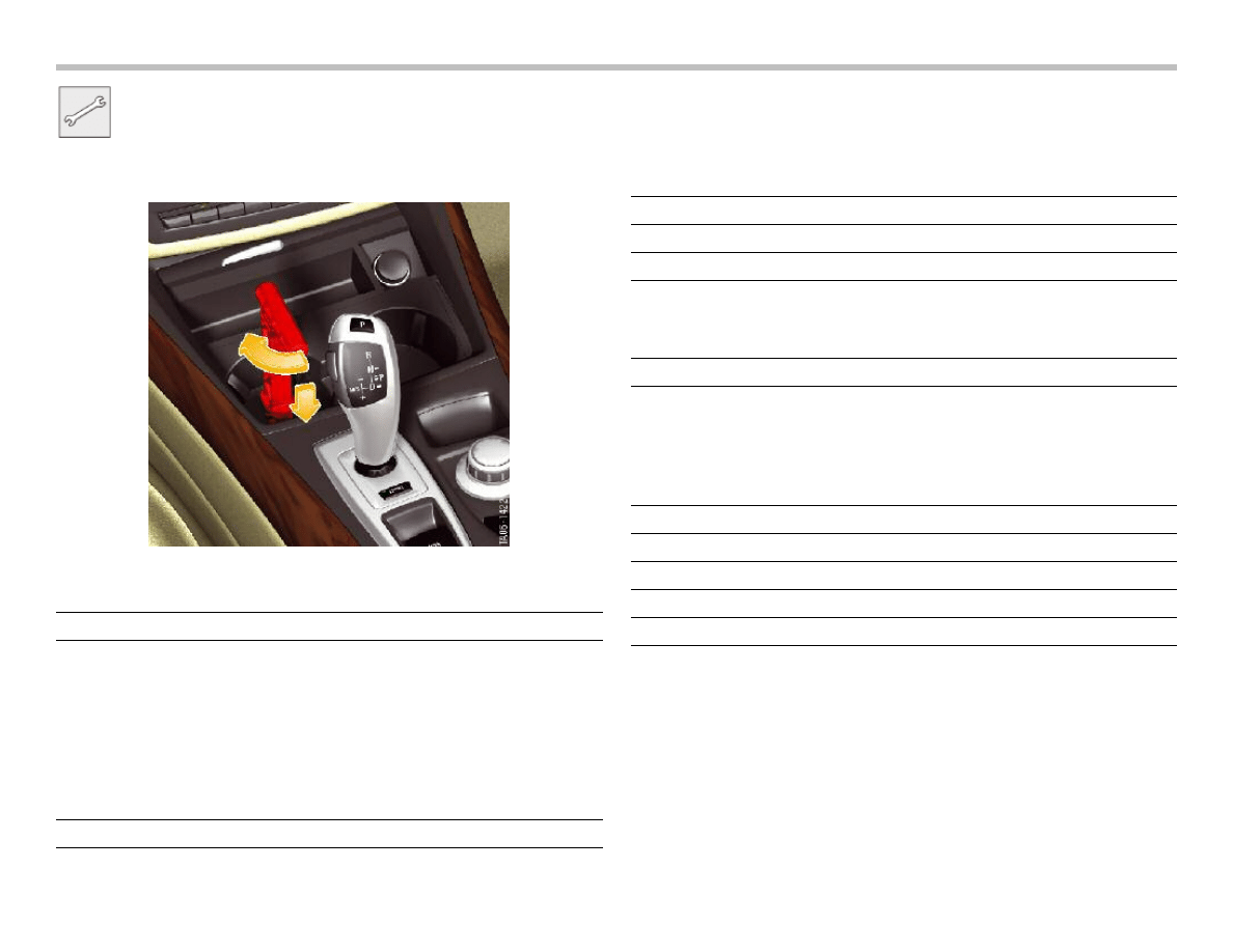
Workshop Exercise - GWS
Demonstrate the emergency release procedure for the E70
transmission as shown below:
When the transmission park lock is released manually, are there any
indications to the driver/technician?
Apply parking brake for safety. Operate shifter through all
modes (P,R,N,D etc.). Note shifter operation and indicator
lights.
With the vehicle is Drive (sport mode), turn off ignition.
What happens to the shifter when the ignition is turned off?
Remove GWS assembly from center console.
Observe proper removal steps with regard to bolts.
What 2 bus systems connect GWS with EGS and Why?
Is there any mechanical connection between GWS and EGS?
Re-install GWS assembly using proper procedures.
Go to diagnostics and look for any status requests or
component activations. List below:
Document Outline
- Main Menu
- E70 Introduction
- E70 Powertrain
- E70 Voltage Supply and Bus Systems
- E70 Chassis Dynamics
- E70 General Vehicle Electronics
- E70 Head-Up Display
- E70 Audio Systems
- E70 Climate Control
- E70 Passive Safety
Wyszukiwarka
Podobne podstrony:
02 F10 Powertrain
02 F01 Powertrain
02a E70 Powertrain
01 E70 Introduction WB
08 E70 Climate Control WB
07 E70 Audio Systems WB
03 E70 Voltage Supply and Bus WB
Wb 20 02
06 E70 Head Up Display WB
09 E70 Passive Safety WB
05 E70 General Vehicle Electronics WB
Wyk 02 Pneumatyczne elementy
02 OperowanieDanymiid 3913 ppt
02 Boża radość Ne MSZA ŚWIĘTAid 3583 ppt
OC 02
więcej podobnych podstron