
Initial Print Date: 12/06
Table of Contents
Subject
Page
New Bus Systems on the E70 . . . . . . . . . . . . . . . . . . . . . . . . . . . . . . . . . . . . . . . . . . . . . . . . . . . . . . . . . . . . . . . . . . . . . . . . . . . . . .10
Diagnosis CAN . . . . . . . . . . . . . . . . . . . . . . . . . . . . . . . . . . . . . . . . . . . . . . . . . . . . . . . . . . . . . . . . . . . . . . . . . . . . . . . . . . . . . . . . . . .11
E70 Voltage Supply and Bus Systems Workbook
Revision Date:

Table of Contents
Subject
Page

Table of Contents
Subject
Page
BLANK
PAGE

4
E70 Voltage Supply and Bus Systems Workbook
Voltage Supply and Bus Systems
Model: E70
Production: From Start of Production
After completion of this module you will be able to:
• Describe changes to the E70 Voltage Supply Systems
• Understand the Bus Systems as applied to the E70
• Understand the new D-CAN and FlexRay
E70 Voltage Supply and Bus Systems Workbook
5
E70 Voltage Supply
With regard to voltage supply on the E70, much of the vehicle is configured in a similar manner to the E9X
vehicles.
With increases in technology, there is an ever-increasing load on the electrical system. As with every new
model, the power supply system becomes more significant.
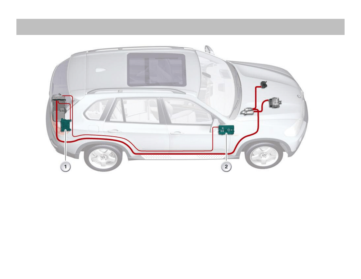
In the E70, there are two power distribution boxes. The front distribution box (2) is below the glovebox and
the rear power distribution box (1) is on the right hand side of the luggage compartment.
The illustration above shows the layout of the primary power supply system components.
Also, there is a distribution box on the battery which contains large capacity fuses.

Overview of System Components
The power supply system of the E70 consists of the following
components:
• Vehicle battery
• Distribution box on the battery
• Rear distribution box on the right-hand side
of the luggage compartment
• Battery cables
• Front distribution box behind the glove compartment
• Junction box control unit
• E-box engine compartment
• Jump start connection point
• Alternator.
The most important new features/changes to the power supply
system in the E70 are described below.
Vehicle Battery
The vehicle battery is installed in the luggage compartment floor.
The vehicle batteries are AGM type, and depending upon equip-
ment, they are either 70 Ah or 90 Ah.
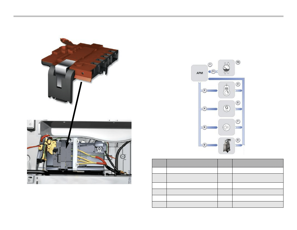
Distribution Box (on battery)
The distribution box in the luggage compartment of the E70 is
mounted directly on the vehicle battery. The rear distribution box on
the battery is secured on the vehicle battery by means of a metal
tab. The metal tabs must be pressed downward and outward in
order to release the distribution box.
The distribution box on the battery is equipped with fuses for the
following electric loads:
• Electrical auxiliary heater (100 A)
• Valvetronic or common rail system (80 A)
• Intelligent battery sensor IBS
• Reserve
• Front distribution box (250 A)
• Rear distribution box (100 A)
• Large electric fan 850 W (100 A)
• Reserve.
The distribution box on the battery should be replaced only as a
complete unit.
The fuses are integrated as a complete unit in the housing of the
distribution box on the battery. The fuses differ in terms of their
power rating. The distribution box additionally contains the power
supply for the BS.
Note: The connectors are color coded and mechanically coded to
avoid confusion. These are high power connections, therefore
always ensure correct contacting!
When replacing or working on the distribution box, always make
sure the plug connections and, above all, that the screw connec-
tions are secured properly.
Connection between battery terminal and distribution box =15 Nm.
6
E70 Voltage Supply and Bus Systems Workbook
Distribution Box (on battery)
Energy Management
The E70 is equipped with Advanced Power Management. This
simply means that the power management system includes the
Intelligent Battery Sensor (IBS).
Much of the system functions the same as the E90 on which it is
based.
E70 Voltage Supply and Bus Systems Workbook
7
Index
Explanation
Index
Explanation
1
Advanced Power Management
7
Electrical loads
2
Idle speed boost
8
Electrical system and battery
diagnosis
3
Engine
9
BMW Diagnostic System
4
Charging voltage target value
10
Intelligent Battery Sensor
5
Alternator
11
Battery Data
6
Electrical load reduction
Workshop Exercise - Power Supply
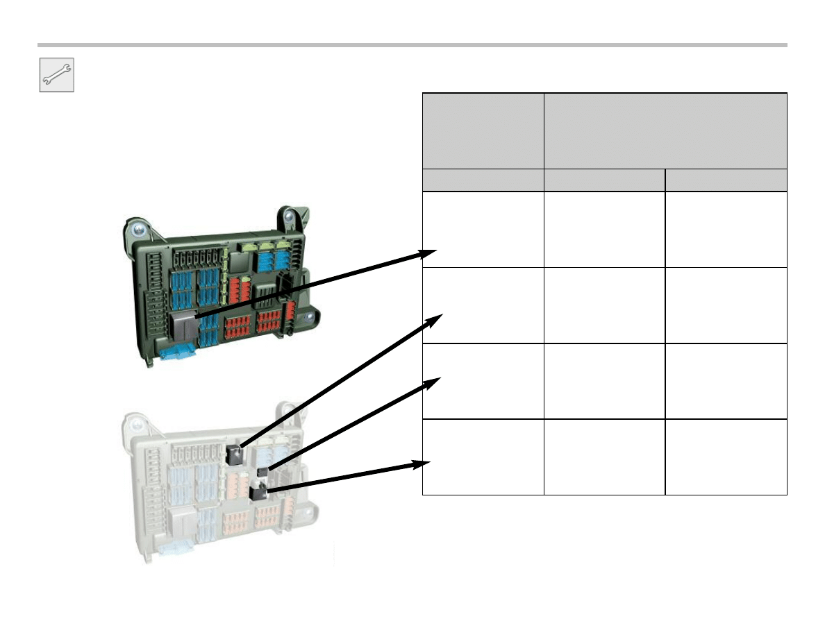
Using the instructor designated vehicle and the ETM’s in
WebTIS, locate the relays in the front & rear power distribution
boxes.
Fill in the chart at the right denoting the relay designation and
whether or not it is soldered to the PC board.
8
E70 Voltage Supply and Bus Systems Workbook
Relay Designation
Soldered
Yes
No
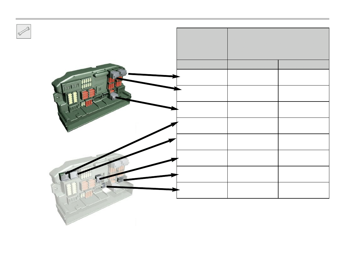
Exercise - Power Supply
Continue with the exercise using the front power distribution box.
E70 Voltage Supply and Bus Systems Workbook
9
Relay Designation
Soldered
Yes
No
10
E70 Voltage Supply and Bus Systems Workbook
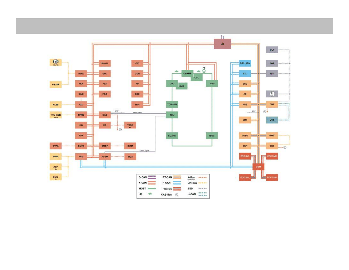
New Bus Systems on the E70
The bus network on the E70 is built upon the foundation from the E90. Many of the bus systems have been carried over.
As far as the E70 bus systems are concerned, there are two new systems not previously used:
• D-CAN - This is the Diagnosis CAN which will be phased into all models from this point.
• FlexRay - FlexRay is currently used only on the Vertical Dynamics Management System (VDM).
Bus Systems
Diagnosis CAN
After connecting a BMW diagnostic system, the gateway (junction
box control unit) places the requests of the BMW diagnostic
system on the internal buses. The responses undergo the same
process in opposite direction.
In future, a new communication protocol will be used for diagnosis.
The D-CAN will replace worldwide the previous diagnostic inter-
face and its protocol which is based on KWP 2000 (Keyword
Protocol 2000).
The reason for the changeover is a new legal requirement in the
USA requiring that all vehicles be equipped with the D-CAN as
from model year 2008. The transitional phase will begin in
September 2006.
This modification will then be phased-in on all BMW models.
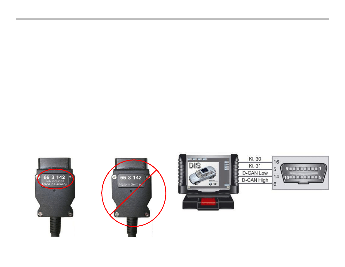
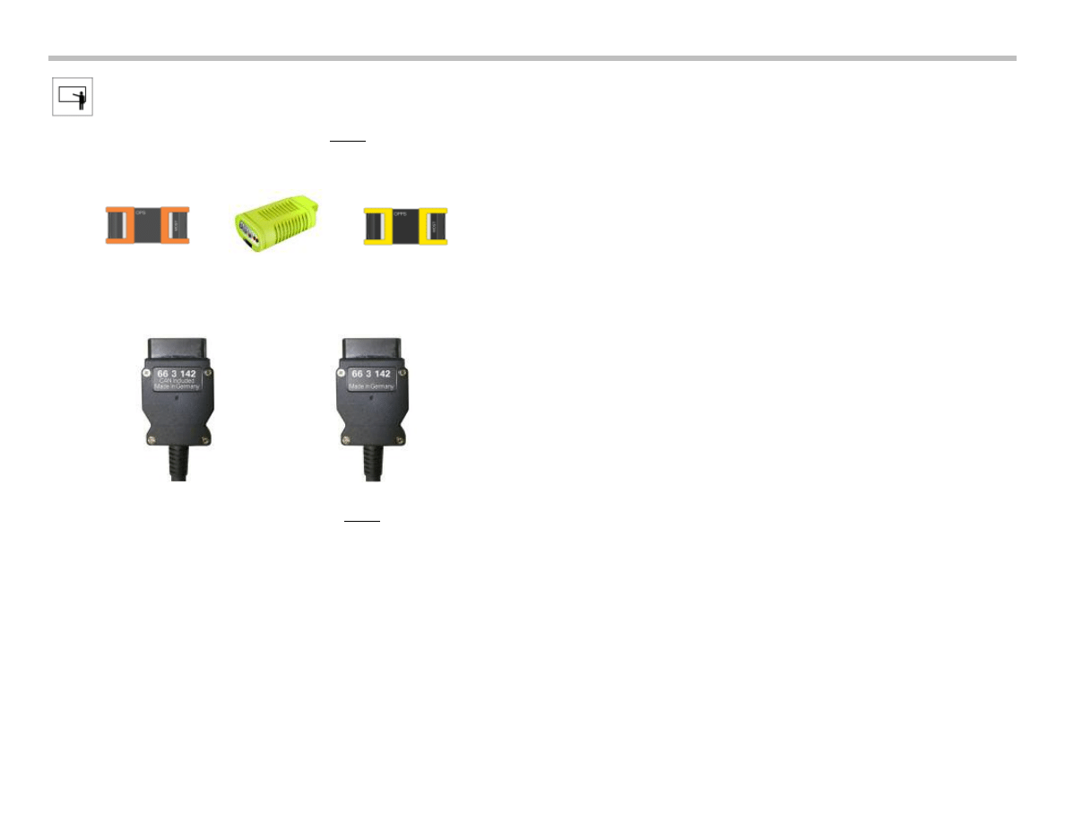
In order to connect diagnostic equipment to a vehicle equipped
with D-CAN, only the OPS or OPPS can be used in conjunction
with the correct cable shown below.
The cable should have the appropriate “CAN Included” markings.
Location of D-CAN Connector
The diagnosis socket is located under the dashboard on the
driver's side in the same location as previous diagnostic
connectors.
D-CAN support with the diagnostic head is technically not possible.
The following interfaces can be used:
• OPS
• OPPS
OBD access in the vehicle will remain unchanged.
The pin assignments are as follows:
• 16 = Terminal 30
• 5 = Terminal 31
• 14 + 6 = Communication connections
The diagnosis socket is located under the dashboard
on the driver's side.
E70 Voltage Supply and Bus Systems Workbook
11
FlexRay
Up until now, the CAN bus format has provided the necessary
speed required for today's vehicle systems. From this point on,
many of the new features and systems will require a more robust
network with much higher communication speeds.
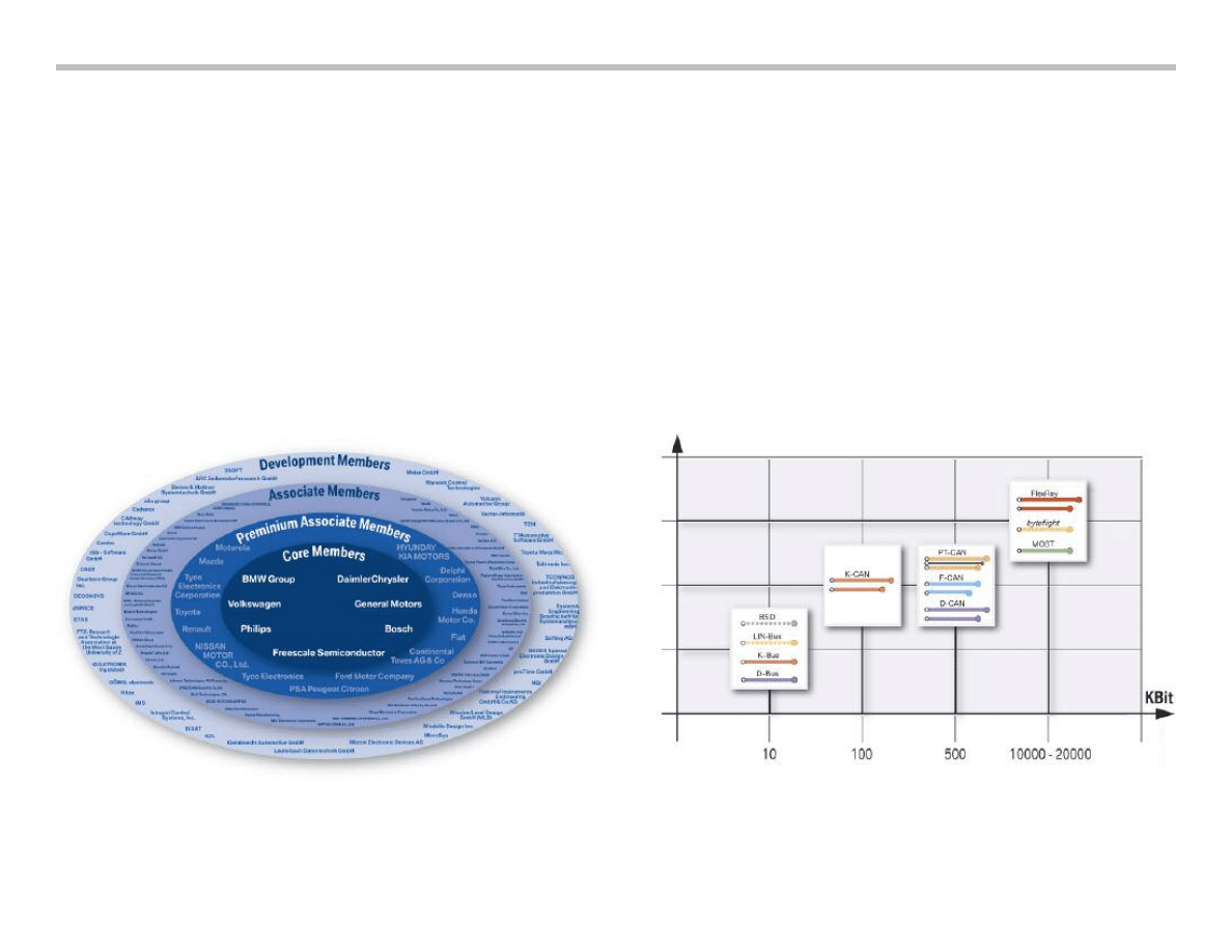
Therefore, in 1999, the FlexRay consortium was founded by
BMW AG, Philips, Motorola (Freescale) and Daimler Chrysler AG.
This consortium set forth developing innovative communication
technology for the future of the automobile.
Since 1999, the FlexRay consortium was joined by additional
partners including GM, Ford, Mazda, Bosch, and Siemens VDO.
Soon after many other automotive industry concerns have signed
on allowing FlexRay to become an industrial standard.
Flexray, with a communication speed of 10 Mbits/second, far
exceeds the current CAN based systems at 500 Kbits/second.
In addition to speed, FlexRay offers efficient “real time” capabilities.
The following outlines the advantages of FlexRay:
• High bandwidth (10 Mbits/s compared to 0.5 Mbits/s of the CAN)
• Deterministic (= real-time capabilities) data transmission
• Reliable data communication
• Supports system integration
• Standard in automotive industry
12
E70 Voltage Supply and Bus Systems Workbook
FlexRay in the E70
E70 Voltage Supply and Bus Systems Workbook
13
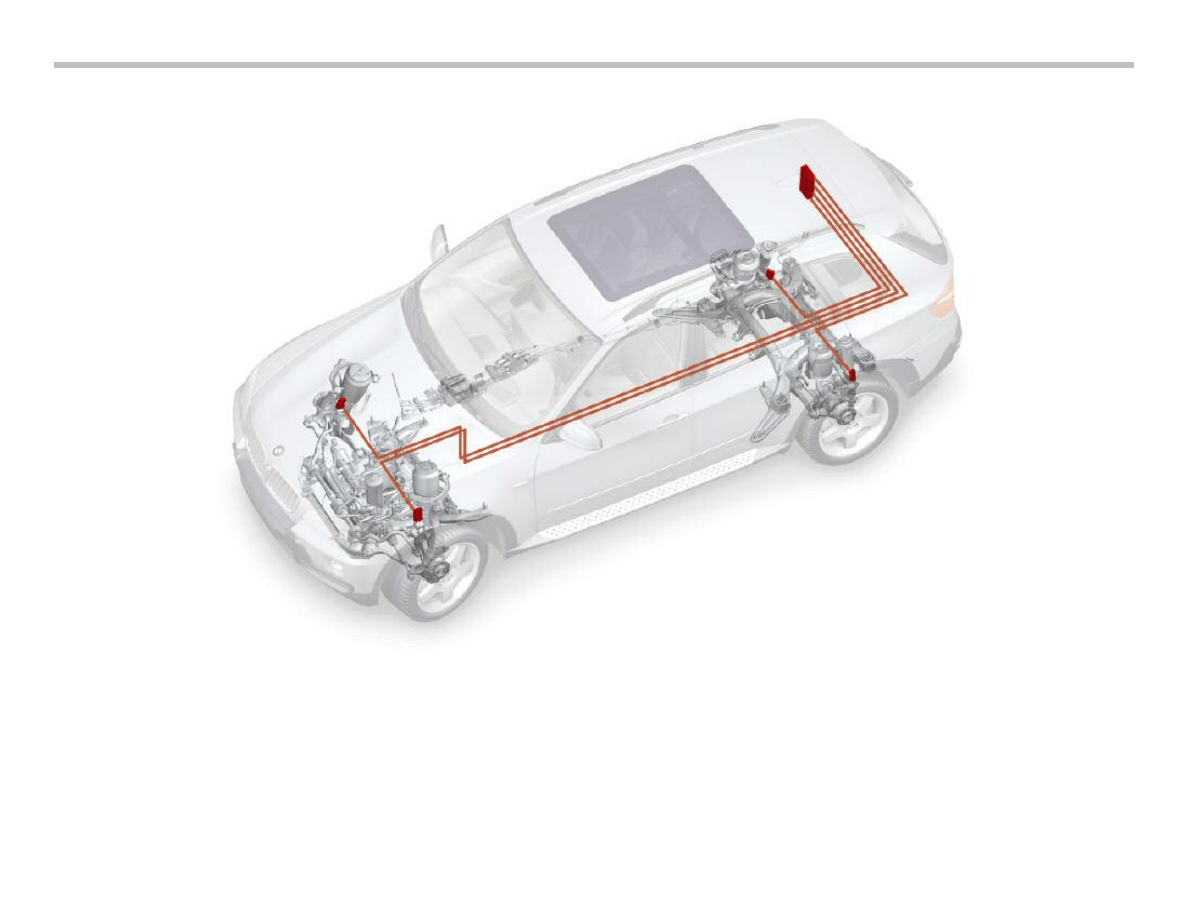
Currently, the only system on the E70 which uses the FlexRay bus system is the Vertical Dynamics
Management (VDM). This system is similar to the EDC system known from existing vehicle.
The use of FlexRay will be expanded in future models. Many powertrain and chassis systems will
adopt this format in order to be compatible with the requirements of future systems.
For more information on FlexRay and VDM, refer to the Chassis Dynamics section of this workbook.
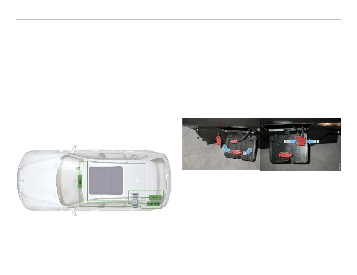
MOST Bus
MOST Users
In the E70, the MOST but is used for the components in informa-
tion/communication systems. The CCC, M-ASK or the CHAMP is
used as the master control unit.
Other bus users may be:
• CD changer/DVD changer
• Top-HiFi amplifier
• Satellite tuner SDARS, IBOC (U.S only)
• Telephone
• Head-up display HUD
The following overview shows a possible equipment configuration.
MOST Access
As on all vehicles equipped with a MOST bus system, direct
MOST access is also provided on the E70.
The direct MOST access is located on the right hand side under
the dashboard in the vehicle interior.
A cover provides direct access to the MOST.
The two connectors are then plugged together. The OPS/OPPS
can now be connected to the connector as usual.
The two connectors must be removed from the holder secured on
the cover.
14
E70 Voltage Supply and Bus Systems Workbook

E70 Voltage Supply and Bus Systems Workbook
15
NOTES
PAGE
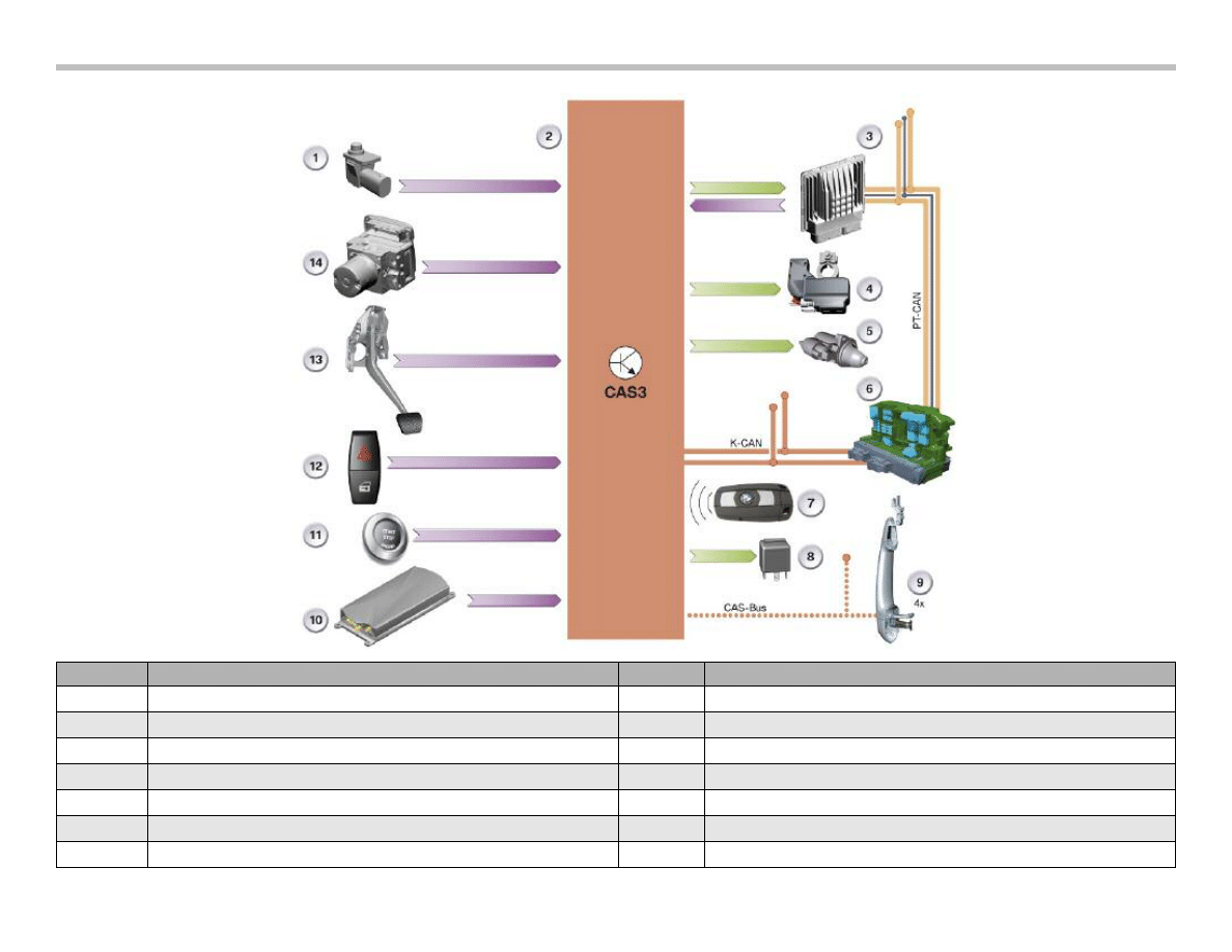
Car Access System 3
16
E70 Voltage Supply and Bus Systems Workbook
Index
Explanation
Index
Explanation
1
Hood contact switch
8
Terminal 15
2
Car Access System 3
9
Electronic Outer Door Handle Module
3
Digital Motor Electronics
10
Telematics Control Unit
4
Intelligent Battery Sensor
11
START-STOP Button
5
Starter
12
Central Lock Button
6
Junction Box Control Unit
13
Brake Light Switch
7
Identification Transmitter
14
Dynamic Stability Control
Car Access System 3 (CAS3)
The Car Access System now features the 3rd generation of control
units. The electronic vehicle immobilizer 4 (EWS 4) is also used in
connection with the Car Access System 3.
The previous functions of the electronic vehicle immobilizer 3 have
been retained. The Car Access System 3 can therefore be operat-
ed together with the electronic vehicle immobilizer 3 or 4.
The digital motor electronics and the Car Access System 3 are
incorporated in the overall electronic vehicle immobilizer system in
the E70.
In addition, the electronic transmission control is used as a further
immobilizer in the E70. The electronic vehicle immobilizer 4
improves the anti-theft properties of the vehicle.
A longer cryptic code is used for the data exchange. The cryptic
code provides the enable to start the engine. The Car Access
System 3 is backwards compatible with the Car Access System 2.
This means the functions of the Car Access System 2 are also
included in the Car Access System 3.
The electronic vehicle immobilizer 3 or the electronic vehicle
immobilizer 4 is used depending on the engine installed and the
associated digital engine management.
The table below shows the assignment of the engine management
to the respective electronic vehicle immobilizer.
History of the Car Access System
The Car Access System was used for the first time in the E65
(03/2002). It has undergone continuous further development and
has been successively introduced in various BMW models.
Functional Overview
The Car Access System 3 is responsible for many functions,
including the master for the following functions:
• Central locking
• Power windows
• Panoramic glass roof
• Comfort Access
The Car Access System 3 enables or interrupts the execution of
the aforementioned functions.
The control units which execute the functions are:
Further functions are integrated in the Car Access System 3.
They are:
• Terminal control
• Electronic vehicle immobilizer 4
• Vehicle data storage
E70 Voltage Supply and Bus Systems Workbook
17
Vehicle
Launch Date
Engine
Engine
Management
EWS
Function
E70
10/06
N62B48O1
ME9.2.3
EWS 3
E70
10/06
N52B30O1
MSV80
EWS 4
Control units which execute functions
Junction Box Control unit (JBE)
Central Locking
Footwell Module (FRM)
Power Windows
Roof Functions Center (FZD)
Panoramic Glass Roof
Comfort Access (CA)
Comfort Access

Electronic Vehicle Immobilizer 3 (EWS 3)
The familiar functions of the previous EWS 3 system have been
retained. The CAS 3 system is integrated in the system network
via the K-CAN. The vehicle key data are read into the Car Access
System 3 via the key slot.
Pin 20 is used in connection with the Car Access System 3.
The enable code is signalled to the digital motor management via
this pin.
The Car Access System 3 contains the start relay that is activated
by means of an integrated circuit. The integrated circuit is informed
via a separate line (A_S_Start) that the digital engine electronics is
ready to start. Furthermore, the start procedure is terminated via
the A_S_Start line if the engine does not start up because, for
example, there is a fault in the PT-CAN system. Data transmission
is unidirectional.
Electronic Vehicle Immobilizer 4 (EWS 4)
The electronic vehicle immobilizer 4 is an immobilizer system that
prevents unauthorized engine start. It was used for the first time in
the CAS 3 system in the E92.
The EWS 4 system uses a new, modern encryption system.
A 128 bit long secret key is assigned to each vehicle and stored in
the BMW database. This secret key is known only to BMW. The
secret key is programmed and locked in the Car Access System 3
and in the digital engine management.
Once entered in the control unit, the secret key can no longer be
changed, deleted or read. This therefore means that each control
unit is assigned to a specific vehicle.
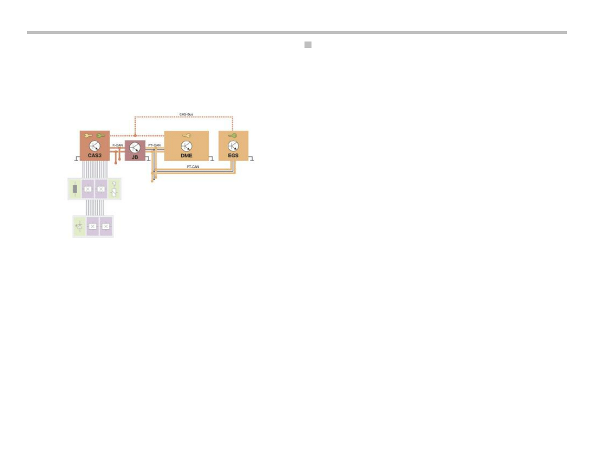
The electronic vehicle immobilizer 4 operates with bidirectional and
redundant data transmission. The K-CAN (CAN protocol) and
CAS-bus (K-bus protocol) are used for this purpose.
Pin 30 of the CAS 3 system serves as the connection to the
CAS-bus.
The redundant data transmission enables operation of the elec-
tronic vehicle immobilizer even if a bus system fails due to a defect.
Design of EWS 4
The vehicle immobilizer consists of the identification transmitter
which identifies itself to the vehicle and therefore to the Car Access
System 3. The Car Access System 3 exchanges data via the CAS-
bus with the digital motor electronics and thus cancels the
immobilizer function.
The software for the electronic vehicle immobilizer as well as the
enable for the starter is resident in the CAS 3. The digital engine
management is responsible for issuing the enable for the ignition
and fuel injection.
The gearbox functions are enabled by the electronic transmission
control. The remote control or the identification transmitter must
be identified as matching the vehicle before the electronic vehicle
immobilizer issues the start enable. This already takes place before
a vehicle is unlocked.
A renewed check (authentication) must be performed as soon as
an attempt is made to start the engine. The check establishes
whether the remote control matches the vehicle or the identifica-
tion transmitter is located in the vehicle interior.
The vehicle can be started if the check is successful.
Authentication starts with the status "Terminal 15 ON".
Note: The start enable can be given only by a remote
control matching the vehicle or a suitable
identification transmitter.
18
E70 Voltage Supply and Bus Systems Workbook
Start Enable through EWS
The start procedure is enabled by means of a special request and
response procedure known as challenge-response. As from
"Terminal 15 ON", the digital engine management sends an
encrypted random number to the CAS 3. The DME (ECM) control
module generates the random number in a random number
generator.
From this random number together with its secret key, the
CAS 3 system calculates a response and sends it to the DME.
In the meantime, the digital engine management calculates the
expected response from the random number with its secret key.
The CAS 3 system and the DME use the same secret key and
algorithm for the calculation. The electronic vehicle immobilizer is
cancelled if the value which the CAS 3 sends to the digital engine
management agrees with the value calculated by the engine
management.
The engine can now be started.
Note: As from "Terminal 15 ON", a cyclic query (challenge-
response) is performed as long as the engine is not yet
running. A fault code is entered in the CAS 3 if there is
no query from the digital engine management approxi-
mately 10 seconds after the start of the request.
Data Transmission
Data transmission is redundant via the bus systems. The signal
from the DME reaches the CAS 3 via the K-CAN and the
CAS-bus.
The DME, however, is connected to the PT-CAN. For this reason,
the signal is sent via the gateway of the junction box control unit to
the K-CAN. The runtime of the signals via the bus systems is of no
significance as the signal that reaches the DME first is used for the
electronic vehicle immobilizer.
The authentication is repeated in response to following events:
• Transmission and response time exceeded
• Transmission problems
• Response with the secret security code incorrect (e.g.
incorrect secret key due to control unit from another vehicle).
Secret Key
The control units are assigned a secret key on the assembly line.
This secret key is generated from a random number. The secret
key is valid for a pair of control units and linked to the specific
vehicle. This means that one pair of control units receives the same
secret key. Once the secret key has been entered, the control unit
is locked. From this point on, the control unit is permanently tied to
this secret key and the vehicle.
The CAS 3 and the digital motor electronics form one pair of
control units.
Note: Since the control units are assigned to the specific
vehicle, replacement with a unit from another vehicle
is not possible. When replacing a control unit, the
new control unit must be ordered from BMW.
Matching of the control units to each other is no
longer necessary.
E70 Voltage Supply and Bus Systems Workbook
19
Gearbox Enable
The enable is based on a procedure similar to that used for EWS 3.
As from "Terminal 15 ON", the CAS 3 sends encrypted individual
codes to the electronic transmission control. The electronic trans-
mission control deciphers and checks these individual codes.
If the check is successful, the gearbox control unit will enable the
gearbox functions.
The electronic gearbox control unit forms a pair of control units
together with the CAS 3.
Start Value Matching
A start value matching procedure between the CAS 3 and the
electronic transmission control is performed on the assembly line.
As part of this procedure, the CAS 3 transfers in encrypted form an
individual code to the electronic transmission control.
Consequently, the electronic transmission control knows the indi-
vidual code and can check whether the gearbox functions can be
enabled.
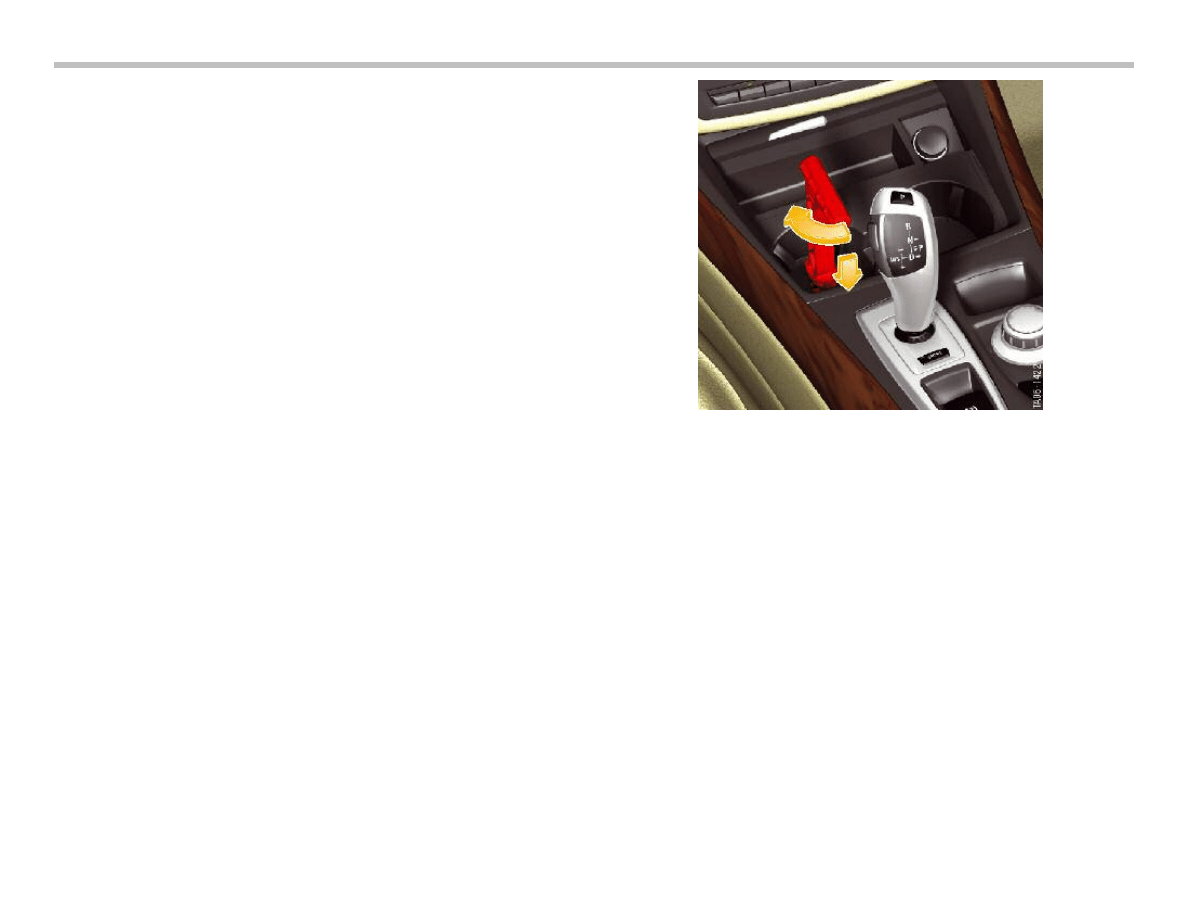
Emergency Release
The parking lock cannot be released in the event of a defect or
data transmission error. For this reason, the E70 features a
mechanical emergency release facility for the parking lock.
A handle for the emergency release of the parking lock is located in
the luggage compartment. This handle must be plugged in under
the left cup holder, turned through 90° and pushed down.
The gearbox is released as soon as the handle has been locked in
position. The vehicle can now be towed but not driven.
Note: The handle must remain locked in position while the
vehicle is being towed. The parking lock will engage if
the handle is removed while the vehicle is being towed.
This could cause an accident in unfavorable towing
situations.
20
E70 Voltage Supply and Bus Systems Workbook

Vehicle Data Storage
The Car Access System 3 stores the following vehicle data:
• Personal Profile, the Car Access System 3 stores data for the
Personal Profile
• Vehicle order, the vehicle order is stored in the footwell module
• Redundant data storage for instrument cluster
• Data for condition-based service CBS
• Authentication for diagnosis access to vehicle
Data for Condition-based Service
The data for condition-based service are stored and transferred to
the remote control.
This data can be read out via the key reader for service purposes.
The data for the condition-based service are updated during vehi-
cle operation. The data in the fault code memory are also updated
during vehicle operation.
The conditions are:
• "Terminal 15 ON", Speed above 50 km/h and below 30 km/h
• The data are updated after covering a distance of 10 km and
at a speed below 30 km/h.
Manual Update of CBS Data
The procedure for transferring current data to the remote control
during servicing is as follows:
• Insert remote control in its holder
• Press and hold center-lock button and select "terminal 15
ON" with the STARTSTOP button.
• After 15 s the CBS data will have been transferred to the
remote control.
• Read out remote control.
Manual Update of Fault Memory Data
The procedure for transferring current data to the remote control
during servicing is as follows:
• Press and hold center-lock button
• Insert remote control in its holder
• Select "Terminal 15 ON" with the START-STOP button
• The fault code memory data are transferred to the remote
control after 15 seconds.
• Read out remote control.
Control Unit Replacement
A defect in the control units belonging to the EWS represents a
challenge for the Service technician. Since a defective control unit
cannot be replaced by control units from other vehicles particular
care is necessary when performing the diagnostic procedure.
A defective control unit can be ordered through spare part
channels. However, it is important to bear in mind that the digital
engine management and the CAS 3 were supplied already coded
to the vehicle.
This has the advantage that only the control unit is replaced and
the matching procedure with the electronic vehicle immobilizer is
not necessary. There is no point in ordering a control unit to be
kept in stock as the secret key is assigned to the control unit and
the vehicle.
A matching procedure is necessary for the electronic transmission
control after replacement. As part of this procedure, the CAS 3
transfers the individual code to the electronic transmission control.
Note: The matching procedure can take several minutes.
E70 Voltage Supply and Bus Systems Workbook
21
22
E70 Voltage Supply and Bus Systems Workbook
Classroom Exercise - Review Questions
1.
Which of the following devices is
NOT compatible with
D- CAN equipped vehicles? (Cross out those not applicable)
2.
Which of the following test cables is compatible with a
D-CAN equipped vehicle? (Circle those that apply)
3.
Circle the bus systems which have
NOT been in use prior to
the introduction of the E70?
LIN
byteflight
MOST
K-CAN D-CAN
BSD PT-CAN
F-CAN
FlexRay
Lo-CAN
4.
What is the communication speed of the FlexRay system?
(circle the applicable answer)
10 Mbits/s
500K/bits/sec
22.5 Mbits/sec
5.
On the E70, which system incorporates the new FlexRay
technology? (Circle those that apply)
VDM
CCC
DSC
FRM
HUD
AS
ARS
DME
6.
The D-CAN signal wires are incorporated into the OBD
connector at pins: (Circle the applicable answer)
5 and 16
16 and 14
5 and 6
14 and 6
7.
The CAS-bus connects: (circle the applicable answer)
DME, CAS 3 and JB
DME, EGS and CAS 3
EGS, GWS and DWA
EGS, JB and FRM
8.
The CAS 3 system is the master for which of the following
functions: (Circle those that apply)
Central locking
Power Windows
Panorama Roof
Comfort Access
9.
On the E70, the KL30g_f relay is located:
(Circle those that apply)
In the front power distribution box
In the rear power distribution box
In the FRM
In the CCC
Document Outline
- Main Menu
- E70 Introduction
- E70 Powertrain
- E70 Voltage Supply and Bus Systems
- E70 Chassis Dynamics
- E70 General Vehicle Electronics
- E70 Head-Up Display
- E70 Audio Systems
- E70 Climate Control
- E70 Passive Safety
Wyszukiwarka
Podobne podstrony:
03a E46 Power Supply and Bus Systems
03 2 F01 Voltage Supply
04a E85 Power Supply and Bus Systems
579393d1434286492 any interest e60 can bus code hacking 10 e60 voltage supply bus systems
C102964 0 SERVICE VOLTAGE SUPPLY
Economics 7 SUPPLY AND?MAND
2006 03 03 zajecia 2 mergers, takeovers and sell offs 2
Hollifield, Miller, Sandas And Slive Liquidity Supply And Demand In Limit Order Markets
2006 03 10 zajecia 3 wrongdoing and corruption 2
06a E70 Displays Indicators and Controls
Dahlia Rose [Dragon 03] A Dragon s Promise [Sugar and Spice] (pdf)
Inverter Negative Voltage Supply using 555 Switching Regulator
05 DFC 4 1 Sequence and Interation of Key QMS Processes Rev 3 1 03
NMS KD 0017 en V01 03 N3000 IMC and ISC User Manual
Supply chain for cheese and desserts
Jvc Power Supply Description And Trouble Shooting Procedure
więcej podobnych podstron