
Initial Print Date: 01/09
Table of Contents
Subject
Page
Voltage Supply Overview . . . . . . . . . . . . . . . . . . . . . . . . . . . . . . . . . . . . . .3
Overview of System Components . . . . . . . . . . . . . . . . . . . . . . . . . . . . . . . .6
Distribution Box on the Battery . . . . . . . . . . . . . . . . . . . . . . . . . . . . . . . . . .7
Rear Fuse Carrier in the Luggage Compartment . . . . . . . . . . . . . . . . . .10
Front Fuse Carrier and Junction Box Electronics . . . . . . . . . . . . . . . . . .13
Internal Plug Connection . . . . . . . . . . . . . . . . . . . . . . . . . . . . . . . . . . . .14
Power Distribution Box in Engine Compartment . . . . . . . . . . . . . . . . . . .18
F01 Voltage Supply
Revision Date:

2
F01 Voltage Supply
Voltage Supply
Model: F01/F02
Production: From Start of Production
After completion of this module you will be able to:
• Locate voltage supply components
• Locate fuse boxes
• Understand overall voltage supply layout
Introduction
Due to the steady increase of electrical functions for comfort, communication and safety
in BMW vehicles, the voltage supply is becoming ever more important.
In the F01/F02, there are two separate fuse carriers. The front fuse carrier is located near
to the glove compartment and the rear fuse carrier is located on the right-hand side of
the luggage compartment.
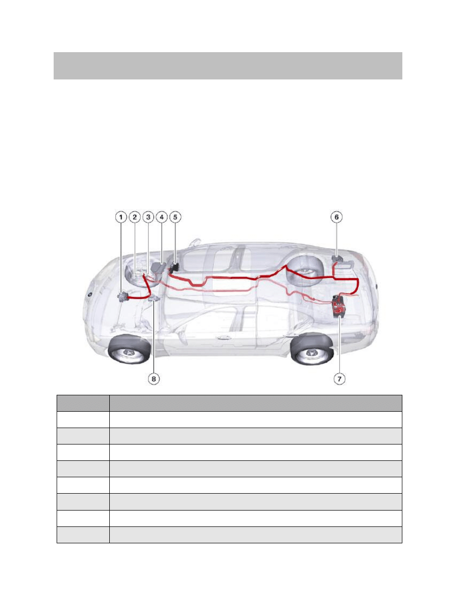
In the graphic below, you can see the layout of the most important components of the
voltage supply in the F01/F02.
3
F01 Voltage Supply
Voltage Supply Overview
Index
Explanation
1
Alternator
2
Positive battery terminal
3
Power distribution box in engine compartment
4
Electronics box in the engine compartment
5
Front fuse carrier behind the glove compartment
6
Rear fuse carrier on the right-hand side of the luggage compartment
7
Battery
8
Starter
Overview of the F01/F02 voltage supply
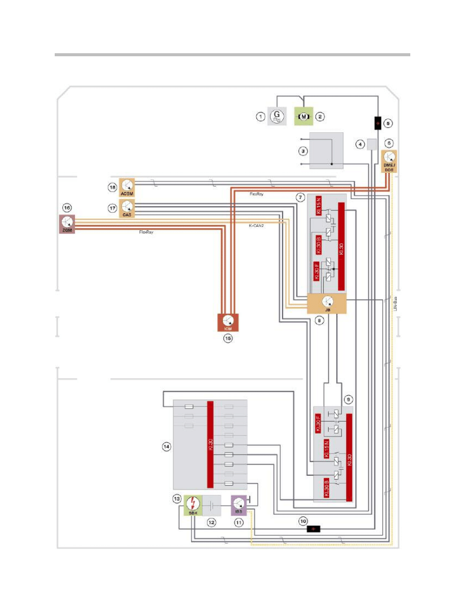
System Circuit Diagram
4
F01 Voltage Supply

5
F01 Voltage Supply
Index
Explanation
1
Alternator
2
Starter
3
Power distribution box in engine compartment
4
Electronics box
5
Positive battery terminal
6
DME Digital Motor Electronics; DDE Digital Diesel Electronics
7
Front fuse carrier, behind the glove compartment
8
Junction box electronics
9
Rear fuse carrier, on the right-hand side of the luggage compartment
10
Transfer point on the luggage compartment floor
11
Intelligent battery sensor IBS
12
Vehicle battery
13
SBK safety battery terminal
14
Distribution box on the battery
15
ICM Integrated Chassis Management
16
ZGM central gateway module
17
Car Access System CAS
18
ACSM crash safety module
KL30
Continuous positive
30
KL30B
Terminal 30 basic operation
KL30F
Terminal 30 fault switched
KL 15N
Terminal 15 overrun
LIN-bus
Local Interconnect Network bus
K-CAN 2
Body controller area network 2

Overview of System Components
The most important new/modified features of the voltage supply in the F01/F02 are
described below. The voltage supply in the F01/F02 consists of the following
components:
• Vehicle battery
• Intelligent battery sensor IBS
• SBK safety battery terminal
• Distribution box on the battery
• Rear fuse carrier on the right-hand side of the luggage compartment
• Battery cables
• Front fuse carrier, behind the glove compartment
• Junction box electronics
• Power distribution box in engine compartment
• Electronics box in engine compartment
• Positive battery terminal
• Alternator
Vehicle Battery
The vehicle battery is fitted in the center at the rear of the luggage compartment floor.
The vehicle battery is always an AGM battery (Absorbant Glass Matt). The AGM battery
has a capacity of 90 Ah.
The main advantage of the AGM battery is its higher cycle strength.
6
F01 Voltage Supply
System Components
AGM battery
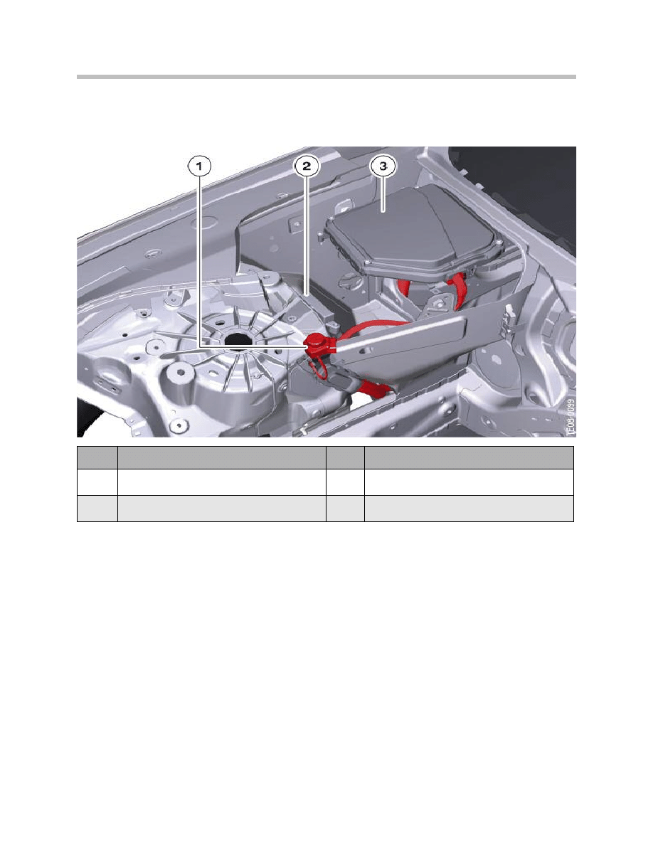
Distribution Box on the Battery
In the F01/F02, the distribution box is located in the luggage compartment directly on top
of the vehicle battery.
The distribution box on the battery is secured on the vehicle battery by means of a metal
tab. The metal tabs must be pressed downward and outward in order to release the distri-
bution box.
The distribution box on the battery is equipped with fuses for the following electric loads:
• Front fuse carrier (250 A)
• Rear fuse carrier (100 A)
• Engine compartment distribution box (100 A)
– large electric fan (850 W or 1000 W)
• Electric coolant pump (100 A)
• Intelligent battery sensor IBS.
7
F01 Voltage Supply
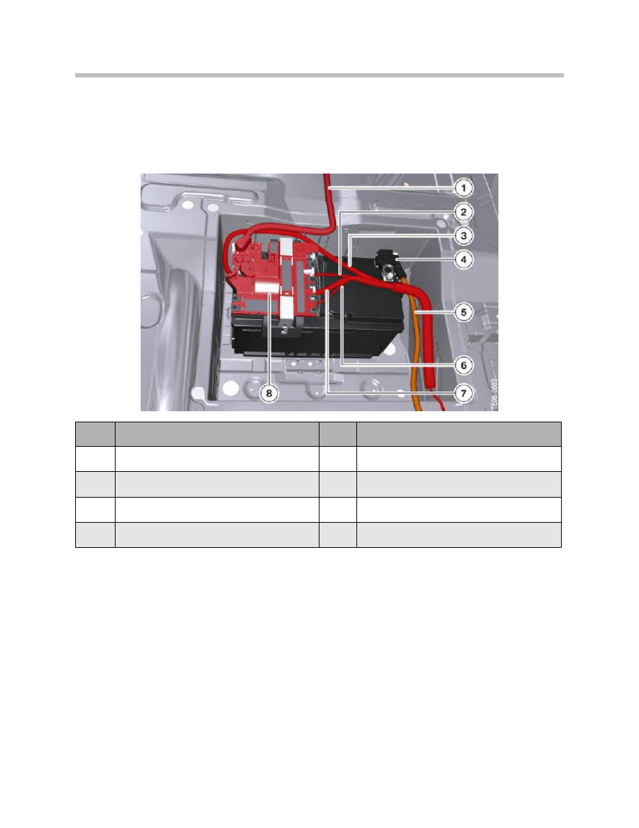
Installation location of the distribution box on the battery in the F01/F02
Index
Explanation
Index
Explanation
1
Battery cable to the starter and alternator 5
5
Negative battery cable
2
Cable to the rear fuse carrier on
the right-hand side
6
Cable to the power distribution box
in the engine compartment
3
Cable to the front fuse carrier
7
Cable to the electronics box
in the engine compartment
4
Intelligent battery sensor IBS
8
Distribution box on the battery
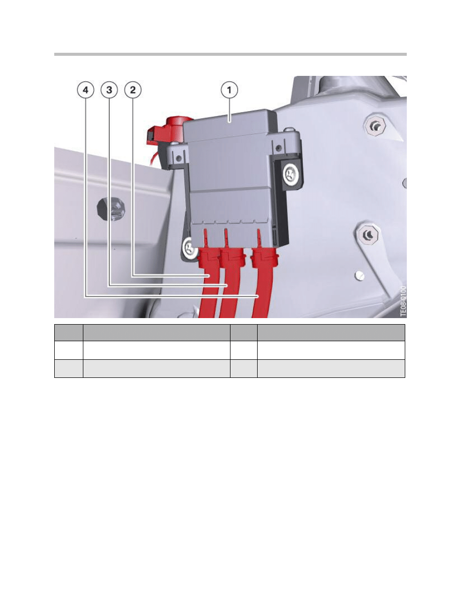
The distribution box on the battery must always be replaced as a complete unit.
The fuses are integrated as a complete unit in the housing of the distribution box on the
battery. The fuses differ in terms of their power rating. The distribution box additionally
contains the power supply for the intelligent battery sensor IBS.
The connectors are color-coded and mechanically coded to avoid confusion. These are
high power connections, therefore always ensure correct contacting!
Note: When replacing or working on the distribution box, always make sure
the plug connections and, above all, the screw connections are secured
properly. Connection between battery terminal and distribution box
15 Nm.
8
F01 Voltage Supply
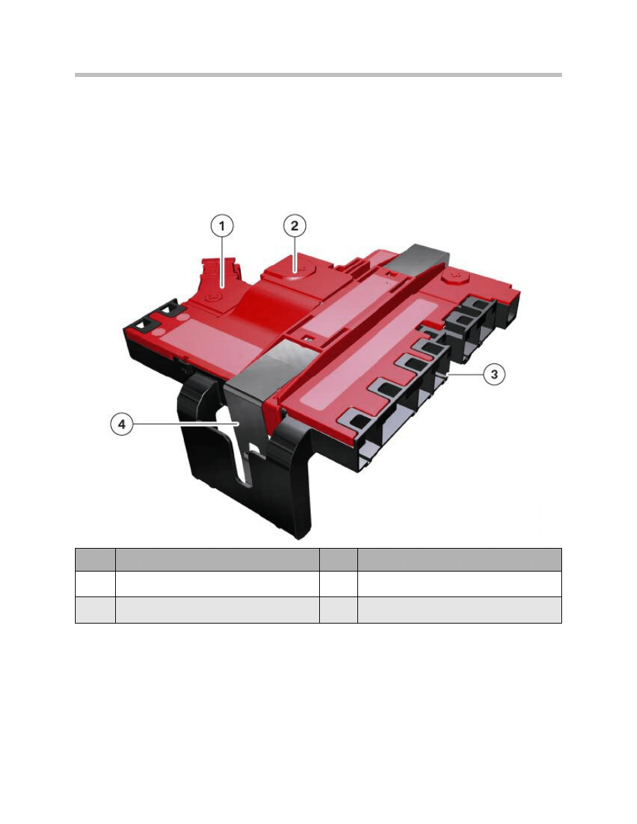
Index
Explanation
Index
Explanation
1
Connection for the battery cable
to the front fuse carrier
3
High current consumer connections
2
Connection to battery terminal
4
Retaining clip
Distribution box on the battery in the F01/F02
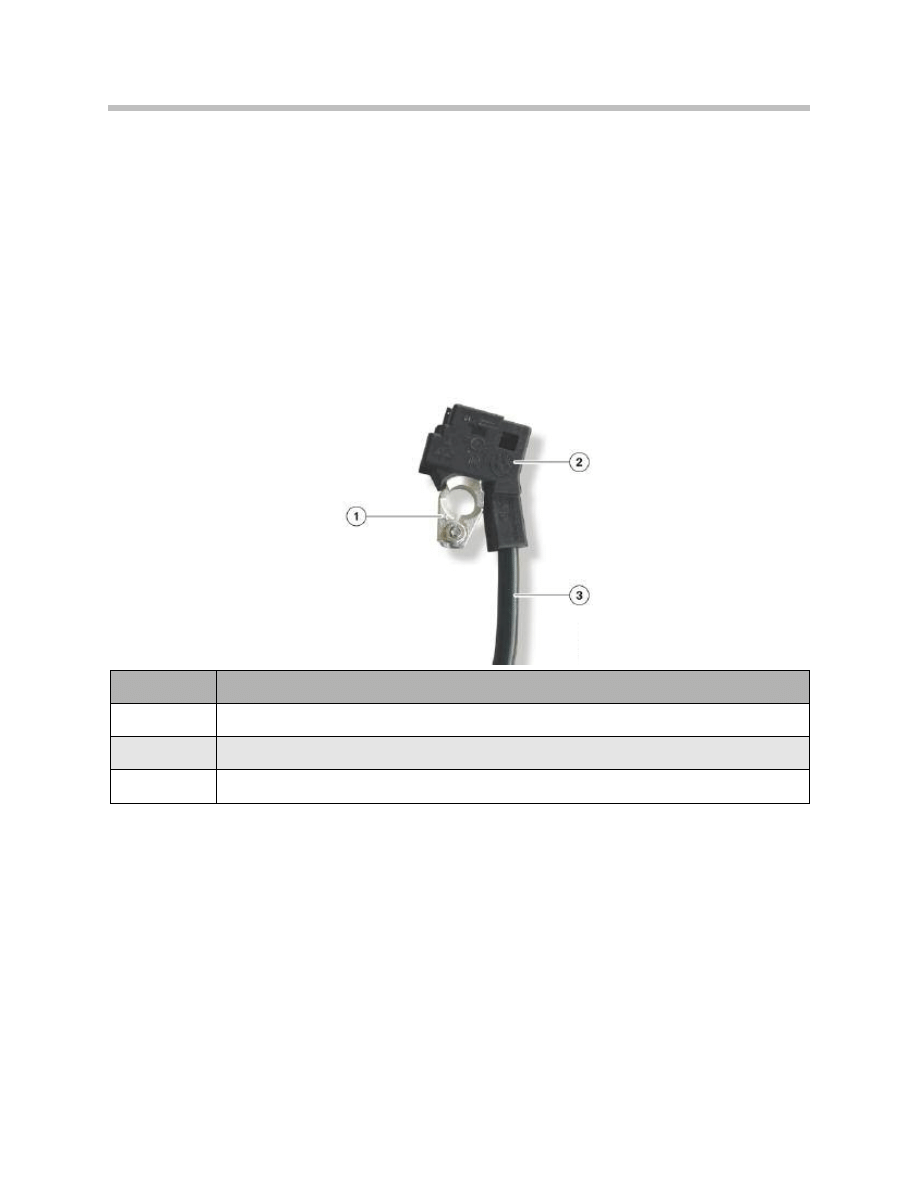
Intelligent Battery Sensor (IBS)
The intelligent battery sensor (IBS) is a mechatronic component for monitoring the bat-
tery status. The following physical measurements are recorded for the battery:
• Current
• Voltage
• Terminal temperature
The term “intelligent” means that there is a microprocessor integrated in the IBS. This
microprocessor calculates and analyses time-critical measured variables. The results are
then forwarded to the higher-level control units (i.e. DME) via the LIN bus.
9
F01 Voltage Supply
Index
Explanation
1
Negative battery terminal
2
Intelligent battery sensor
3
Negative battery cable
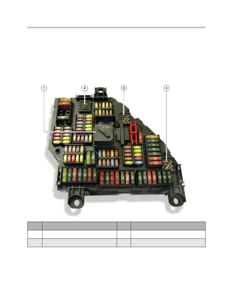
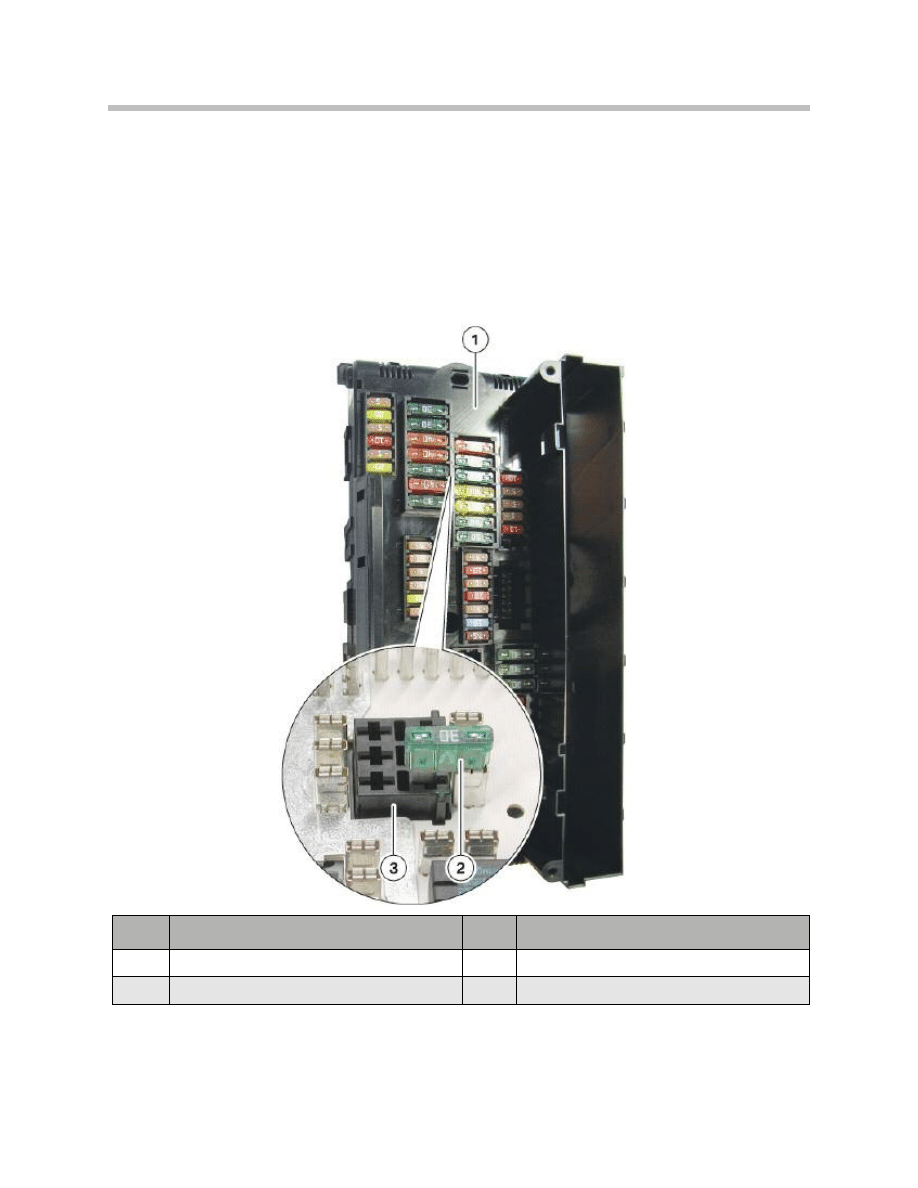
Rear Fuse Carrier in the Luggage Compartment
Due to the large number of consumers and control units in the F01/F02, an additional
fuse carrier has been fitted in the luggage compartment.
As well as the fuses, a few relays are plugged in here or soldered to the circuit board.
If one of the soldered relays is faulty, the rear distribution box must be replaced as a whole
unit. The connection port of the battery cable is located on the rear of the fuse carrier.
10
F01 Voltage Supply
Index
Explanation
Index
Explanation
1
Relay terminal 30B (plugged in)
3
Relay terminal 15N (soldered)
2
Relay terminal 30F (soldered)
4
Relay for the heating element in
the rear window (soldered)
External view of the rear fuse carrier in the F01/F02
Battery Cables
In the F01/F02, three main power lines on the underbody run from the distribution box at
the battery to the engine compartment. One of the main power lines runs via the positive
battery terminal to the starter motor and to the alternator.
The second line powers the engine electronics (and electric coolant pump).
The third line runs to the distribution box in the engine compartment. This distribution
box supplies the electric fan with power. This line is safeguarded by the high-current fuse
(100 A) in the distribution box at the battery.
11
F01 Voltage Supply
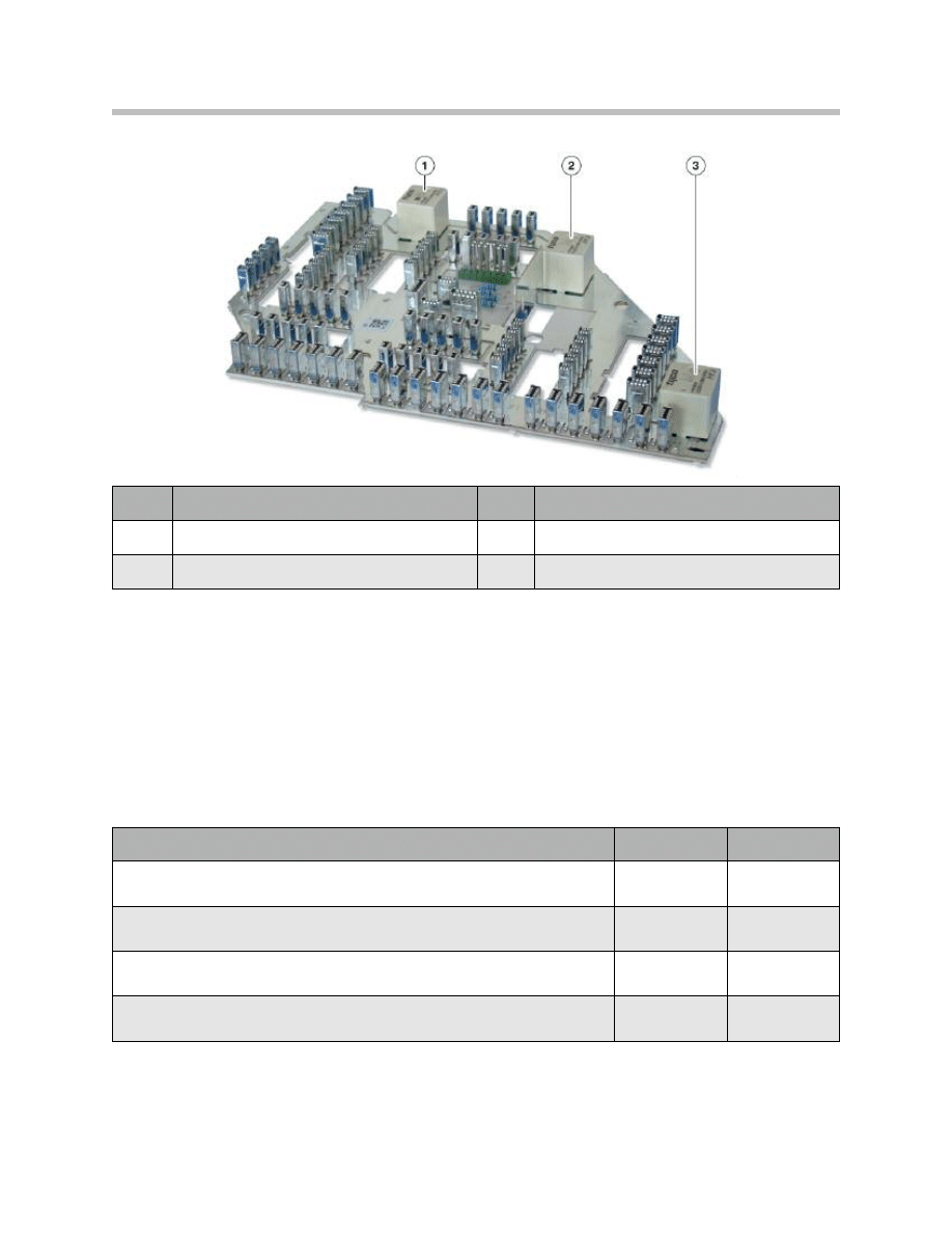
Index
Explanation
Index
Explanation
1
Relay terminal 30F
3
Relay for the heating element in the rear window
2
Relay terminal 15N
Internal view of the rear fuse carrier in the F01/F02
Cable
Cross section
Material
Cable to the starter motor and alternator
110 mm2
Aluminum
Cable to the front distribution box, behind the glove compartment
25 mm2
Copper
Cable to the rear fuse carrier
10 mm2
Copper
Cable to the power distribution box in the engine compartment
16 mm2
Copper
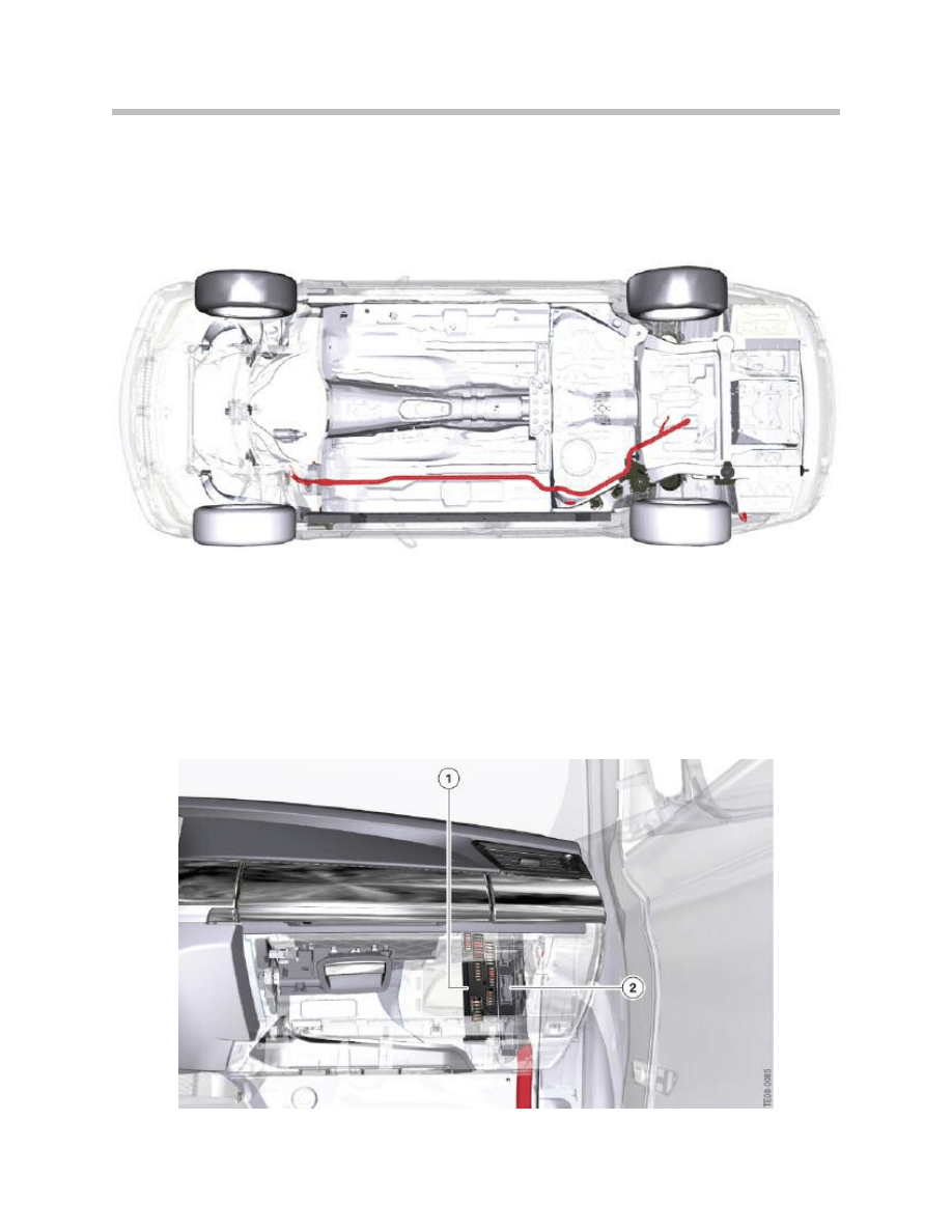
In addition, a battery cable is routed to the front fuse carrier through the vehicle interior.
The transfer points for the main power cables are located in the luggage compartment.
The main power lines on the underbody are laid in a protected area to prevent damage.
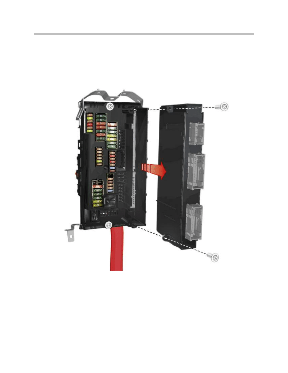
Front Fuse Carrier
This section describes the front fuse carrier(1). In the right-hand part of the front fuse
carrier, there is an opening through which the junction box electronics (2) are connected
to the front fuse carrier.
The front fuse carrier is located underneath the dashboard on the right-hand side.
In order for a fuse to be replaced, the glove compartment must be opened.
12
F01 Voltage Supply
Routing of battery cable on the underbody in the F01/F02
Installation location of the front fuse carrier in the F01/F02
Front Fuse Carrier and Junction Box Electronics
The connection between the front fuse carrier and the junction box electronics is estab-
lished through the opening in the right-hand area of the fuse carrier. An internal plug
connection provides the electrical connection between the two components.
When assembled, the two components form a single unit (junction box) consisting of
the junction box electronics and the front fuse carrier.
The fuse carrier and junction box electronics components must be replaced separately.
In addition to the corresponding test modules in the diagnostics, diagnosis cables are
also available with which electrical measurements can be made directly on the control-
unit plugs and on the internal interface.
13
F01 Voltage Supply
Junction box electronics and front fuse carrier in the F01/F02
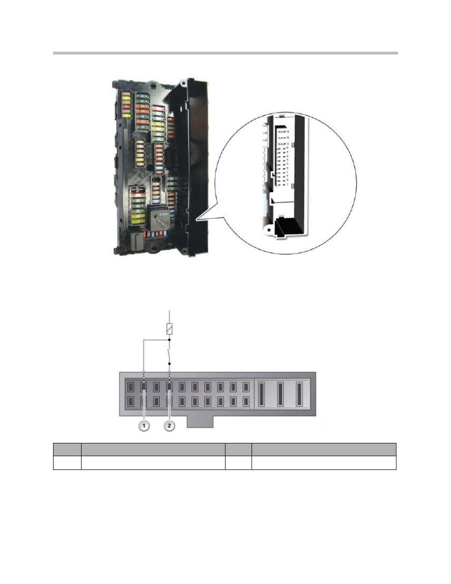
Internal Plug Connection
The internal plug connection is located on the right hand side, inside the opening for the
junction box electronics.
The internal plug connection is responsible for Relays in the front fuse carrier activating
the relays in the front fuse carrier. In addition, the correct functioning of these relays is
monitored by the junction box electronics
There are a few relays in the front fuse carrier. One of these is plugged in, the others are
soldered to the circuit board.
14
F01 Voltage Supply
Plug connector
Internal plug connection for the junction box electronics in the F01/F02
Index
Explanation
Index
Explanation
1
Monitoring connection
2
Actuation connection
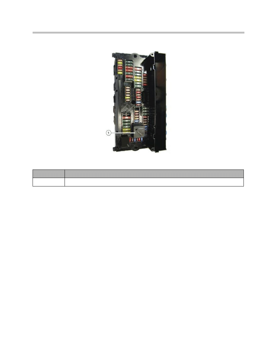
Connected Relay
15
F01 Voltage Supply
Index
Explanation
1
Relay terminal 30B
Front view of the front fuse carrier in the F01//F02
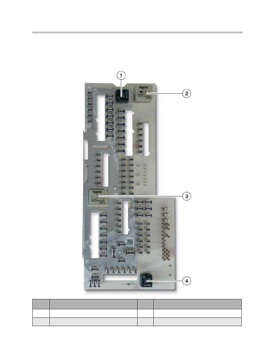
Soldered Relay
Various relays are soldered to the circuit board in the front fuse carrier. In the event of a
fault, the fuse carrier must be replaced as a complete unit.
16
F01 Voltage Supply
Index
Explanation
Index
Explanation
1
Relay, terminal 30F (bistable)
3
Relay, terminal 15N
2
Relay for the headlight cleaning system
4
Horn relay
Internal view of the front fuse carrier, F01/F02
Direct Contacting
On the distribution boxes, direct contacting to the fuses is carried out. The fuses are
plugged into the plug connections on the circuit board with a connection. The other plug
connections are directly connected to the connecting plugs on the wiring harness.
The advantages of this design modification are:
• Improved package space utilization
• Improved heat dissipation.
Particular care must be taken to ensure that the fuses are fitted firmly when unplugging
and reconnecting the connectors for the wiring harness. The fuses must be braced when
plugging in the wiring harness.
17
F01 Voltage Supply
Index
Explanation
Index
Explanation
1
Front fuse carrier housing
3
Wiring harness connector
2
Fuse
Direct contacting of fuses in the F01/F02
Power Distribution Box in Engine Compartment
There are no fuses in the engine compartment distribution box.
18
F01 Voltage Supply
Index
Explanation
Index
Explanation
1
Positive battery terminal
3
Electronics Box
2
Power distribution box in engine compartment
19
F01 Voltage Supply
Index
Explanation
Index
Explanation
1
Power distribution box in engine compartment
3
Cable to electric fan
2
Cable from distribution box to battery
4
Not for US market
Document Outline
- Main Menu
- 01_F01 Introduction
- 02_F01 Powertrain
- 03_F01 Voltage Supply & Bus Systems
- 03.1_F01 Bus Systems
- 03.2_F01 Voltage Supply
- 03.3_F01 Energy Management
- 03.4_F01 Car Access System 4
- 04_F01 Chassis Dynamics
- 04.1_F01 Chassis and Suspension
- 04.2_F01 Dynamic Driving Systems
- 04.3_F01 Longitudinal Dynamics Systems
- 04.4_F01 Lateral Dynamics Systems
- 04.5_F01 Vertical Dynamics Systems
- 04.6_F01 Cruise Control Systems
- 05_F01 General Vehicle Electronics
- 05.1_F01 Comfort Access
- 05.2_F01 Central Locking System
- 05.3_F01 Automatic Soft Close
- 05.4_F01 Power Windows
- 05.5_F01 Sliding Tilting Sunroof
- 05.6_F01 Anti-theft System
- 05.7_F01 Automatic Luggage Compartment Lid
- 05.8_F01 Exterior Lighting
- 05.9_F01 Interior Lighting
- 05.10_F01 Wiper-Washer System
- 05.11_F01 Exterior Rear View Mirrors
- 05.12_F01 Seats
- 05.13_F01 Steering Column Switch Cluster
- 06_F01 Driver Information Systems
- 06.1_F01 Displays Indicators and Controls
- 06.2_F01 Head-up Display
- 06.3_F01 BMW Night Vision 2
- 06.4_F01 Active Blind Spot Detection System
- 06.5_F01 KAFAS
- 06.6_F01 PDC-TRSVC
- 07_F01 Information and Communication Technology
- 07.1_F01 Rear Seat Entertainment Systems
- 07.2_F01 Telephone System
- 07.3_F01 Voice Activation System
- 07.4_F01 Audio Systems
- 08_F01 Climate Control
- 09_F01 Passive Safety Systems
- 10_F01 Service Information
- 10.1_F01 System Functions
- 10.2_ISTA-Programming
Wyszukiwarka
Podobne podstrony:
03 E70 Voltage Supply and Bus WB
C102964 0 SERVICE VOLTAGE SUPPLY
PBO G 03 F01 Drill records of Contingency plan ships
579393d1434286492 any interest e60 can bus code hacking 10 e60 voltage supply bus systems
03 3 F01 Energy Management
03 1 F01 Bus Systems
Inverter Negative Voltage Supply using 555 Switching Regulator
SP6FIN 160m HF receiver ECC82 low power supply voltage
A 12kw Switching Mode Power Supply With Free Input Voltage
Low Voltage Power Supply Circuits
03 Sejsmika04 plytkieid 4624 ppt
03 Odświeżanie pamięci DRAMid 4244 ppt
podrecznik 2 18 03 05
od Elwiry, prawo gospodarcze 03
więcej podobnych podstron