
Initial Print Date:01/09
Table of Contents
Subject
Page
The Energy Circuit in the Vehicle . . . . . . . . . . . . . . . . . . . . . . . . . . . . . . . . .5
Bus Overview and Terminal Status . . . . . . . . . . . . . . . . . . . . . . . . . . . . . . .7
Power Management . . . . . . . . . . . . . . . . . . . . . . . . . . . . . . . . . . . . . . . . .10
Charging Voltage Target Value . . . . . . . . . . . . . . . . . . . . . . . . . . . . . . . . . .10
Effect of outside temperature . . . . . . . . . . . . . . . . . . . . . . . . . . . . . . . .11
Class A electrical devices . . . . . . . . . . . . . . . . . . . . . . . . . . . . . . . . . . .13
Class B electrical devices . . . . . . . . . . . . . . . . . . . . . . . . . . . . . . . . . . .14
Advanced Power Management . . . . . . . . . . . . . . . . . . . . . . . . . . . . . . . . .16
Vehicle in stationary mode . . . . . . . . . . . . . . . . . . . . . . . . . . . . . . . . . . .16
Electric loads in stationary mode . . . . . . . . . . . . . . . . . . . . . . . . . .16
Stationary load log-off . . . . . . . . . . . . . . . . . . . . . . . . . . . . . . . . . . .16
Intelligent Battery Sensor (IBS) . . . . . . . . . . . . . . . . . . . . . . . . . . . . . . . . .23
Engine management (power management) . . . . . . . . . . . . . . . . . . . .27
F01 Energy Management
Revision Date:

Subject
Page
Indication of battery condition . . . . . . . . . . . . . . . . . . . . . . . . . . . . . . . .28
Functions switched off/modified in transport mode . . . . . . . . . . . . .30
Electrical System and Battery Diagnosis . . . . . . . . . . . . . . . . . . . . . . . . .34

Subject
Page
BLANK
PAGE

4
F01 Energy Management
Energy Management
Model: F01/F02
Production: From Start of Production
After completion of this module you will be able to:
• Understand changes to the Energy Management
The Energy Circuit in the Vehicle
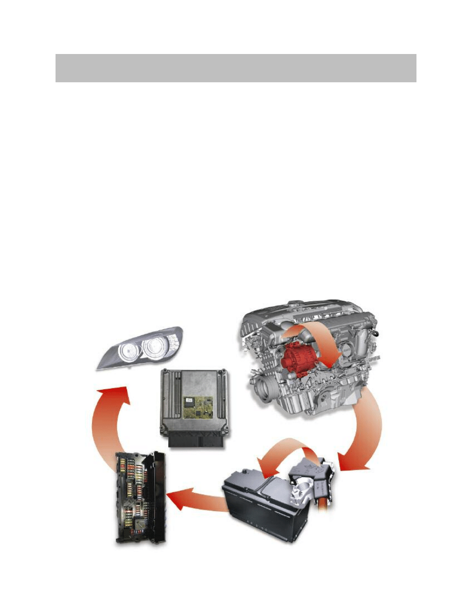
The vehicle’s electrical energy system comprises all components for generating, storing,
distributing and converting electrical energy.
The job of the vehicle’s electrical energy system is to supply and distribute electrical
energy in all vehicle operating situations. The aim is to provide all electrical components
with the necessary electrical energy in all vehicle situations.
The highest-priority aims are maintaining the vehicle’s ability to start and trouble-free
operation of the vehicle when it is being driven. Another aim is to minimize wear (high
battery energy throughput) and prevent damage to components (total battery discharge)
of the vehicle’s electrical system by networking, dimensioning and appropriate control of
devices that consume, store and convert electrical energy.
Like the other current BMW Group models, the F01/F02 uses an energy management
system to ensure balanced use of energy on the vehicle.
The energy management functions are integrated in the power management system
that is implemented in the form of software on the engine management module.
5
F01 Energy Management
Introduction

Energy management encompasses a large number of functions such as:
• Power terminal shut-down
• Electric load shut-down
• Determining required battery charge voltage
• Enabling battery discharge
• Idle speed boost
• Detecting battery condition
• Vehicle programming.
The sections that follow describe only the most important changes
to the energy management system.
6
F01 Energy Management
7
F01 Energy Management
Bus Overview and Terminal Status
The F01/F02 introduces new designations for some of the terminals. A distinction is also
made between logical terminals and power supply terminals. The logical terminals are:
• Terminal R
• Terminal 15
• Terminal 50.
The power supply terminals are:
• Terminal 30
• Terminal 15N
• Terminal 30B
• Terminal 30F.
The logical terminals do not serve as power supply terminals; instead, they represent
a status. They are activated/deactivated by pressing the START-STOP button.
The table below details the previous and new terminal designations.
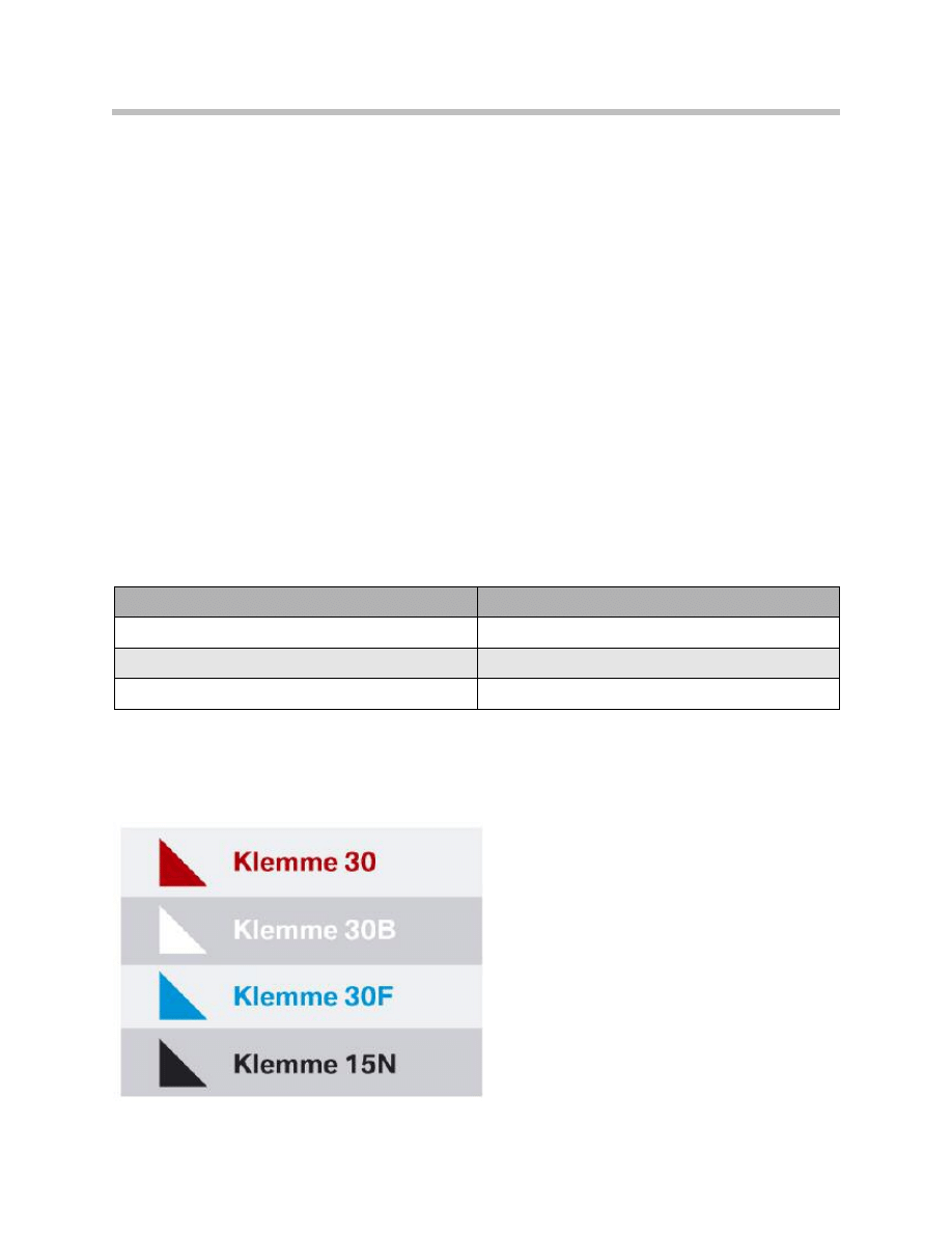
For clearer illustration of terminal shut-down, the control units are identified by a colored
triangle. Identification and allocation to the individual terminals are shown in the diagram
below.
Color coding
Previous
New
Terminal 15
Terminal 15N
Terminal 30g
Terminal 30B
Terminal 30g_f
Terminal 30F
8
F01 Energy Management
5
PT-C
AN2
P
T-
C
A
N
K
-C
A
N
K
-C
A
N
2
5
F
R
M
F
Z
D
IH
K
A
E
H
C
S
M
B
F
H
S
M
FA
H
H
K
L
S
M
FA
S
M
B
F
F
K
A
H
U
D
C
ID
F
D
F
D
2
T
R
S
V
C
H
iF
i
V
S
W
H
S
R
IC
M
A
L
S
W
W
C
O
N
U
L
F
-S
B
X
H
ig
h
S
D
A
R
S
T
C
U
T
O
P
H
iF
i
D
V
D
R
S
E
M
id
E
M
A
LI
E
M
A
R
E
D
S
C
S
Z
L
N
V
E
K
A
FA
S
E
M
F
G
W
S
E
K
P
S
E
G
S
T
P
M
S
C
IC
E
D
C
S
V
R
E
D
C
S
H
R
E
D
C
S
V
L
E
D
C
S
H
L
V
D
M
JB
P
D
C
C
A
S
S
S
K
O
M
B
I
A
C
S
M
D
M
E
S
Z
G
M
S
OBD
K
le
m
m
e
3
0
K
le
m
m
e
3
0
F
K
le
m
m
e
1
5
N
K
le
m
m
e
3
0
B
K
le
m
m
e
3
0
B
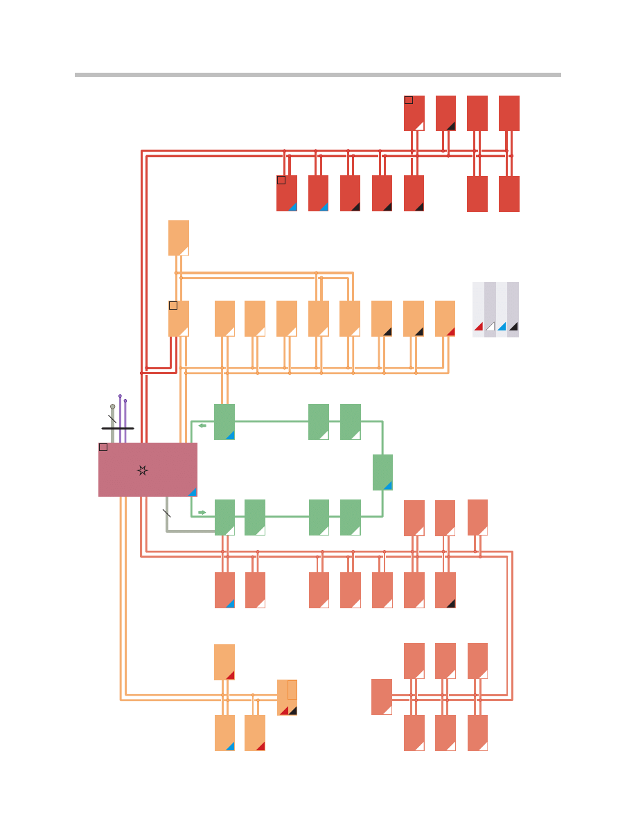
Control units and terminal shut-down on F01/F02

9
F01 Energy Management
Index
Explanation
Index
Explanation
AL
Active steering
HKL
Tailgate lift
CAS
Car Access System
HSR
Rear suspension slip angle control
CIC
Car Information Computer
HUD
Head-up display
CID
Central information display
ICM
Integrated Chassis Management
CON
Controller
IHKA
Automatic climate control
DME
Digital Motor Electronics
JBE
Junction Box electronics
DSC
Dynamic Stability Control
KAFAS
Camera-based driver assistance systems
DVD
DVD changer
Kombi
Instrument cluster
EDC SHL
Electronic Damper Control,
rear left satellite unit
NVE
Night Vision module
EDC SHR
Electronic Damper Control,
rear right satellite unit
PDC
Park Distance Control
EDC SVL
Electronic Damper Control,
front left satellite unit
OBD
Diagnosis connector
EDC SVR
Electronic Damper Control,
front right satellite unit
RSE-Mid
Rear seat entertainment
EGS
Electronic transmission control unit
SDARS
Satellite tuner
EHC
Electronic ride-height control
SMBF
Front passenger seat module
EKPS
Electric fuel pump control unit
SMBFH
Rear passenger-side seat module
EMA LI
Motorized reel, left
SMFA
Driver's seat module
EMA RE
Motorized reel, right
SMFAH
Rear driver's-side seat module
EMF
Electromechanical parking brake
SWW
Lane departure warning
FCON
Rear Controller
SZL
Steering column switch cluster
FD
Rear display
TCU
Telematics Control Unit
FD2
Rear display 2
TOP-HIFI
Top-HiFi system
FKA
Rear climate control
TPMS
Tire pressure monitoring system
FLA
Main beam assistant
TRSVC
Control unit for reversing camera and
SideView
FRM
Footwell module
ULF-SBX
Interface box (ULF functionality)
FZD
Roof function center
VDM
Vertical dynamics management (central con-
trol unit for electronic damper control)
GWS
Gear selector switch
VSW
Video switch
HiFi
HiFi amplifier
ZGM
Central Gateway Module
The power management system is a subsystem of the energy management system.
The power management functions are carried out by the engine management module
(DME ).
The power management system regulates the power consumption of some of the most
important electrical devices and the power output of the alternator while the vehicle is
being driven.
Only advanced power management (APM) is used on the F01/F02.
In addition to the main functions of basic power management (idling speed and required
battery charge voltage), APM also incorporates the following extended functions:
• Electric load reduction
• Electric load shut-down
• Vehicle systems diagnosis
• Battery diagnosis.
Idle Speed Boost
On vehicles with gasoline engines, the idling speed is raised by up to 200 rpm as soon
as current starts to be drawn from the battery despite the alternator working at full
capacity.
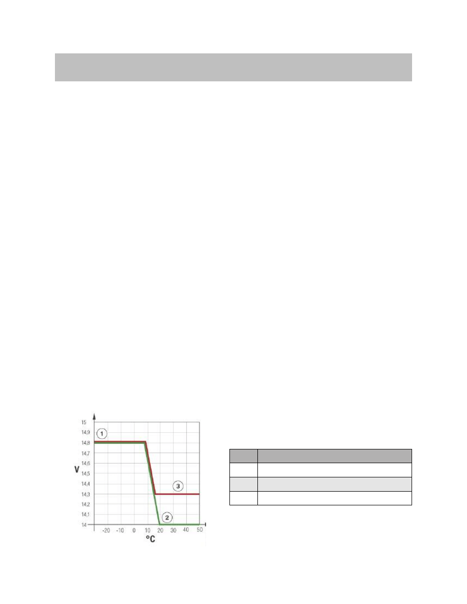
Charging Voltage Target Value
The required battery charge voltage is determined according to outside temperature and
IGR function.
10
F01 Energy Management
Power Management
Index
Explanation
1
Model-based battery temperature of 8 °C
2
Model-based battery temperature of 19 °C
3
Emergency operation
Voltage regulation on alternator on F01/F02

Effect of Outside Temperature
The required battery charge voltage function ensures electrochemically optimum battery
charging by adjusting the battery charge voltage according to temperature. Since the
current absorbed by a cold battery is lower, the voltage for charging must be higher than
for a warm battery.
Conversely, if that higher voltage were constantly used to charge a warm battery, there
would be a risk of gas formation. Therefore, the charge voltage is regulated on the alter-
nator according to temperature. The current battery temperature is measured by the
intelligent battery sensor (IBS) attached directly to the battery negative terminal and sig-
nalled to the engine management module (DME) via the LIN bus.
The power management uses this value as the input variable for calculating the battery
temperature. With the aid of a calculation model, the specified charging voltage is set
based on the battery temperature. This information is sent to the alternator via the bit-
temperature of serial data interface (BSD).
11
F01 Energy Management
Battery Regeneration
In order to ensure the availability of IGR Low, a certain level of unused capacity must
always be retained in the battery. That is implemented by means of IGR High and IGR
Medium. For the battery, that means that it is never fully charged. If a battery were not
fully charged over a long period or were left fully discharged, sulphation could occur.
Sulphation causes a battery to prematurely age, thereby reducing the usable proportion
of its rated capacity. To prevent that occurring, the required battery charge voltage func-
tion performs a battery regeneration cycle in the course of which the battery is fully
charged.
On vehicles with IGR function, regular battery regeneration phases are maintained in
order to protect the battery against premature aging and loss of capacity due to cyclic
discharge and sulphation. That involves the battery being fully charged using the maxi-
mum permissible charge voltage taking account of ambient conditions (temperature,
charge level).
Emergency Operation
The APM makes use of emergency operation set to a constant 14.3 V. A fault code func-
tions when there is a break in the LIN “Communication LIN” is entered in the fault inter-
face. In this case, the alternator voltage is code memory of the engine management.
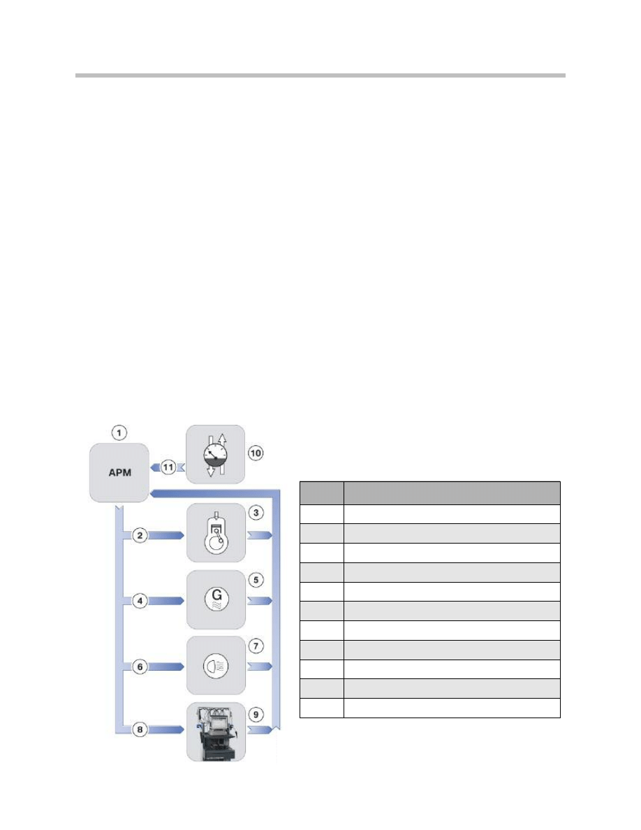
APM Control System
12
F01 Energy Management
Index
Explanation
1
Advanced power management
2
Idle speed boost
3
Combustion engine
4
Charging voltage target value
5
Alternator
6
Electric load reduction
7
Electric loads
8
Electrical system and battery diagnosis
9
BMW diagnostic system
10
Intelligent battery sensor
11
Battery data

Electric Load Reduction
In order to reduce the power consumption in critical situations, not only can the idling
speed be increased and the required charge voltage raised, the power of various non-
essential electrical devices can be reduced or they can be switched off altogether.
That prevents the battery being discharged.
The electrical devices (that consume power when the engine is running) are subdivided
into two classes.
• Class A
A reduction of the power consumption or shut-down of these devices is only notice-
able to the driver to a limited degree or after a delay. Individual Class A devices are
only switched off or have their power consumption reduced under the following 2
conditions:
– Battery charge status in critical range
– High load on alternator.
• Class B
A reduction of the power consumption or shut-down of these functions is immedi-
ately noticeable to the driver. Individual Class B devices are only switched off or have
their power consumption reduced under the following condition:
– Battery charge status in critical range.
Class A Electrical Devices
The following measures are taken for Class A devices under the conditions specified
above:
13
F01 Energy Management
Sequence Function
Operation
Control unit
1
Rear window defogger
Clocking
IHKA
2
Seat heating, rear
Electric auxiliary heater, rear
Stage 2
75%
SM FAH SM BFH JB
FKA
3
Seat heating, front
Seat heating, rear
Stage 2
50%
SM FA SM BF JB
SM FAH SM BFH JB
4
Electric auxiliary heater, rear
50%
FKA
5
Seat heating, front
Seat heating, rear
50%
Stage 1
SMFA SMBF JB
SM FAH SM BFH JB
6
Electric auxiliary heater, rear
Steering wheel heating
25%
50%
FKA
SZL
7
Electric auxiliary heater, rear
Mirror heating
Washer-jet heating
OFF
OFF
OFF
FKA
FRM/JB
JB
8
Steering wheel heating
OFF
SZL
9
Seat heating, front
Seat heating, rear
OFF
OFF
SMFA SMBF JB
SM FAH SM BFH JB

All measures are implemented in the specified order.
Class B Electrical Devices
The following measures are taken for Class B devices under the conditions specified
above:
All measures are implemented in the specified order.
Once the battery charge level is outside the critical range, the functions are fully available
again.
Note: While shut-down of individual devices or reduction of their power con-
sumption is active, the displays remain active (LEDs remain on).
Note: If devices have their power consumption reduced or are switched off, a
fault memory entry is registered and the history memory records the
duration, odometer reading, and the function concerned.
14
F01 Energy Management
Sequence
Function
Operation
Control unit
10
Rear window defogger
OFF
IHKA
Top-HiFi system or
BMW individual high end audio
system
Maximum 30 A power
consumption after
engine started
Top HiFi High End Audio
Sequence
Function
Operation
Control unit
1
Top-HiFi system or BMW indi-
vidual high end audio system
Heater fan, front and rear
Maximum 30 A power
consumption in general
75%
Top HiFi High End Audio
IHKA FKA HKA
2
Heater fan, front and rear
50
IHKA FKA HKA
3
Heater fan, front and rear
25%
IHKA FKA HKA

15
F01 Energy Management
NOTES
PAGE

Advanced Power Management
Vehicle in Stationary Mode
Electric loads in stationary mode
Certain electric loads may be active even when the closed-circuit current monitoring facil-
ity of the power management is already in operation. This is necessary for various rea-
sons:
• Legally required electric loads, e.g. side lights, hazard warning system
• Convenience for the customer, e.g. radio function, telephone.
These electric loads must be excluded from the closed-circuit current monitoring system
in order to avoid misinterpretation in the power management. For this purpose, these
electric loads must log in with the power management.
In turn, the power management recognizes the activity and accepts the higher power
consumption when the systems are deactivated, the corresponding control units log off
from the power management.
Stationary load log-off
The power management in the engine control can send a request to switch off the active
electric loads in stationary mode depending on the battery charge status and the start
capability limit. The electrical devices operating when the vehicle is in stationary mode
must then deactivate their functions irrespective of the terminal status and must have
attained their closed-circuit current within 5 minutes. Legally required electric loads are
excluded from this function.
16
F01 Energy Management

New Terminal Designation
The F01/F02 introduces new designations for some of the terminals. A distinction is also
made between logical terminals and power supply terminals. The logical terminals are:
• Terminal R
• Terminal 15
• Terminal 50.
The logical terminals do not serve as power supply terminals; instead, they represent a
status. They are activated/deactivated by pressing the START-STOP button. Their status
is signalled to the control units by means of a bus message.
The power supply terminals are:
• Terminal 30
• Terminal 15N
• Terminal 30B
• Terminal 30F.
The table below details the previous and new terminal designations.
17
F01 Energy Management
Terminals
Previous
New
Terminal 15
Terminal 15N
Terminal 30g
Terminal 30B
Terminal 30g_f
Terminal 30F
Terminal
Description
Terminal 15
Terminal 15N
Terminal R
Radio setting
Terminal 30
Continuous positive
Terminal 30g
Continuous positive, time dependent
Terminal 30g_f
Continuous positive, fault dependent

Terminal 15N
Terminal 15N is used to supply power to control units and components that are only
intended to be active when the vehicle is being driven, e.g. PDC.
The letter “N” stands for “Nachlauf”, meaning “overrun”. The power supply Terminal 15N
is switched on and off by means of the logical Terminal 15. The overrun time after
Terminal 15N is switched off is 5 seconds. That time is required so that the control units
have enough time to save their data. While Terminal 15N is active, Terminal 30B and
Terminal 30F are also active.
Terminal 30B
Terminal 30B supplies power to control units and electrical components
that are required when the driver is present.
The letter B stands for “Basic mode”.
Terminal 30B is activated by:
• Pressing the buttons on the radio remote control
• Unlocking/locking/double-locking the vehicle
• Pressing the START-STOP button
• Change of door switch status, change of trunk switch status,
change of side-window position
• Bus message.
Regular deactivation by:
• Vehicle double-locked and tailgate closed (one minute overrun)
• Vehicle not double-locked or tailgate open (30 minutes overrun).
Other possible deactivation triggers:
• Upper starting capacity limit reached (one minute overrun)
• “Powerdown”: diagnosis command for purposes of measuring
closed-circuit (10 seconds overrun)
• Transport mode (one minute overrun).
While Terminal 30B is active, Terminal 30F is also active.
18
F01 Energy Management

Terminal 30F
Terminal 30F supplies power to control units and electrical devices that are also required
when the driver is not present but which can be switched off in the event of a fault.
Use: all control units that are not supplied by Terminal 15N or Terminal 30B, are not
responsible for vehicle access and do not have to meet a legal requirement for permanent
operation.
The letter “F” stands for “Fault”.
Terminal 30F is activated by:
• Pressing the buttons on the radio remote control
• Unlocking/locking/double-locking the vehicle
• Pressing the START-STOP button
• Change of door switch status, change of tailgate switch status,
change of side-window position
• Bus message.
In the event of a fault (closed-circuit current too high, bus wake-up, sleep-mode inhibitor,
start capacity limit reached) Terminal 30F is reset for 10 seconds.
Terminal 30F is not reset or switched off if at least one of the following conditions is met:
• Terminal 30B active
• Parking lights switched on
• Side lights switched on
• Hazard warning lights switched on
• If an extended overrun time for Terminals 30B and 30F is demanded by a service
message from any of a number of control units. Example: when the engine is warm,
it can be necessary for the electric fan to run on for up to 11 minutes after the vehi-
cle is parked and locked. In order for the electric fan to be operated, the engine man-
agement module must be supplied with power. Since the overrun time in that case
is only three minutes (that is currently the short overrun time for Terminal 30B, not
one minute), the DME requests the appropriate extension by way of a bus message
when the engine is switched off.
• “Sticking relay” detected.
Terminal 30F is switched off if Terminal 30B is off and at least one of the following
conditions is met:
• Starting capacity limit reached
• Another 10 bus wake-ups have occurred after Terminal 30F reset
• Unexplained bus activity after Terminal 30F reset
• Violation of closed-circuit current limit detected after Terminal 30F reset.
19
F01 Energy Management
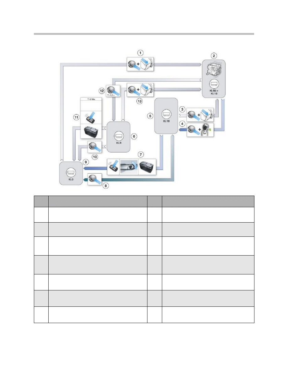
Terminal control
20
F01 Energy Management
Index
Explanation
Index
Explanation
1
START-STOP button pressed and brake pedal oper-
ated --> Terminal 50 is activated and engine starts
8
Pressing the START-STOP button toggles termi-
nal status between Terminal 15 and Terminal 0.
2
Engine running (Terminal 50 > Terminal 15)
9
Terminal 0
3
START-STOP button pressed and brake pedal oper-
ated —> Engine starts.
10
Pressing the START-STOP button changes the
terminal status from Terminal R to Terminal 0.
4
If selector lever is in position “N” and the engine is
stopped by pressing the START-STOP button,
Terminal 15 remains on for 15 minutes.
11
Change from Terminal R to Terminal 0 if more
than 8 minutes elapsed or vehicle is locked or
starting capacity limit reached.
5
Terminal 15
12
START-STOP button briefly pressed -> Engine
stops. Terminal R.
6
Terminal R
13
START-STOP button pressed and brake pedal
operated —> Engine starts.
7
Terminal 15 OFF when vehicle is locked or starting
capacity limit reached.

Terminal Relays
The F01/F02 has various relays for switching off the power supply to most control units.
The Junction box module controls the bistable relays for Terminal 30F but receives the
request from the central gateway module (ZGM) or IBS.
• ZGM: If sleep mode inhibited or on occurrence of unauthorized wake-up.
ZGM monitors the vehicle status and registers inhibited sleep mode or unauthorized
wake-up after Terminal 30B is switched off.
• IBS: If closed-circuit current limit violated or starting capacity limit reached.
The computation for activating the Terminal 30F relay takes place on two control units.
The ZGM monitors the following activities:
• Invalid wake-up procedures within the bus systems
• Sleep blockers (control units that constantly keep the bus systems active).
The ECM (DME) continuously reads and assesses the battery data. The relay is also
switched off when the starting capability limit of the vehicle battery is reached.
The Terminal 30F relay is a bistable relay and is always in the ON state under normal con-
ditions. It switches off the connected electric loads only in the case of fault. Once the
Terminal 30F relay has been switched off, one of the switch-on conditions must be met
before it can be switched on again.
Note: More information on this topic can be found in the Reference Information
on the CAS.
21
F01 Energy Management
Location
Relay
Connection
Controlled by:
Front fuse box
KL 15N
Soldered
CAS
Front fuse box
KL 30B
Plugged in
CAS
Front fuse box
KL30F (bistable)
Soldered
ZGM/DME
Rear fuse box
KL 15N
Soldered
CAS
Rear fuse box
KL 30B
Plugged in
CAS
Rear fuse box
KL30F (bistable)
Soldered
ZGM/DME

General Measures
The terminals "load shut-down" and the terminal "interior lighting" are switched off as a
general measure when the vehicle is in stationary mode. This occurs only when the vehi-
cle is not locked and secured. These loads are shut down immediately when the vehicle
is locked and secured. This measure affects the following electric loads:
22
F01 Energy Management
Electric loads
Terminal
Interior lighting (front and rear
Load shut-down after 8 minutes (immediately if double locked)
Footwell lighting (front and rear)
Load shut-down after 8 minutes (immediately if double locked)
Reading light (front and rear)
Load shut-down after 8 minutes (immediately if double locked)
Vanity mirror light
Load shut-down after 8 minutes (immediately if double locked)
Components
The components of the energy management system are:
• Engine
• Alternator
• Vehicle battery
• Intelligent battery sensor
• Junction box module
• Engine management (power management)
• Loads.
The most important components of the energy management system are described
in the following.
Intelligent Battery Sensor (IBS)
The intelligent battery sensor has a similar range of functions to the intelligent battery
sensor on previous models. A new feature is data transmission between the IBS and the
engine management module via LIN bus and the wake-up function of the IBS.
23
F01 Energy Management
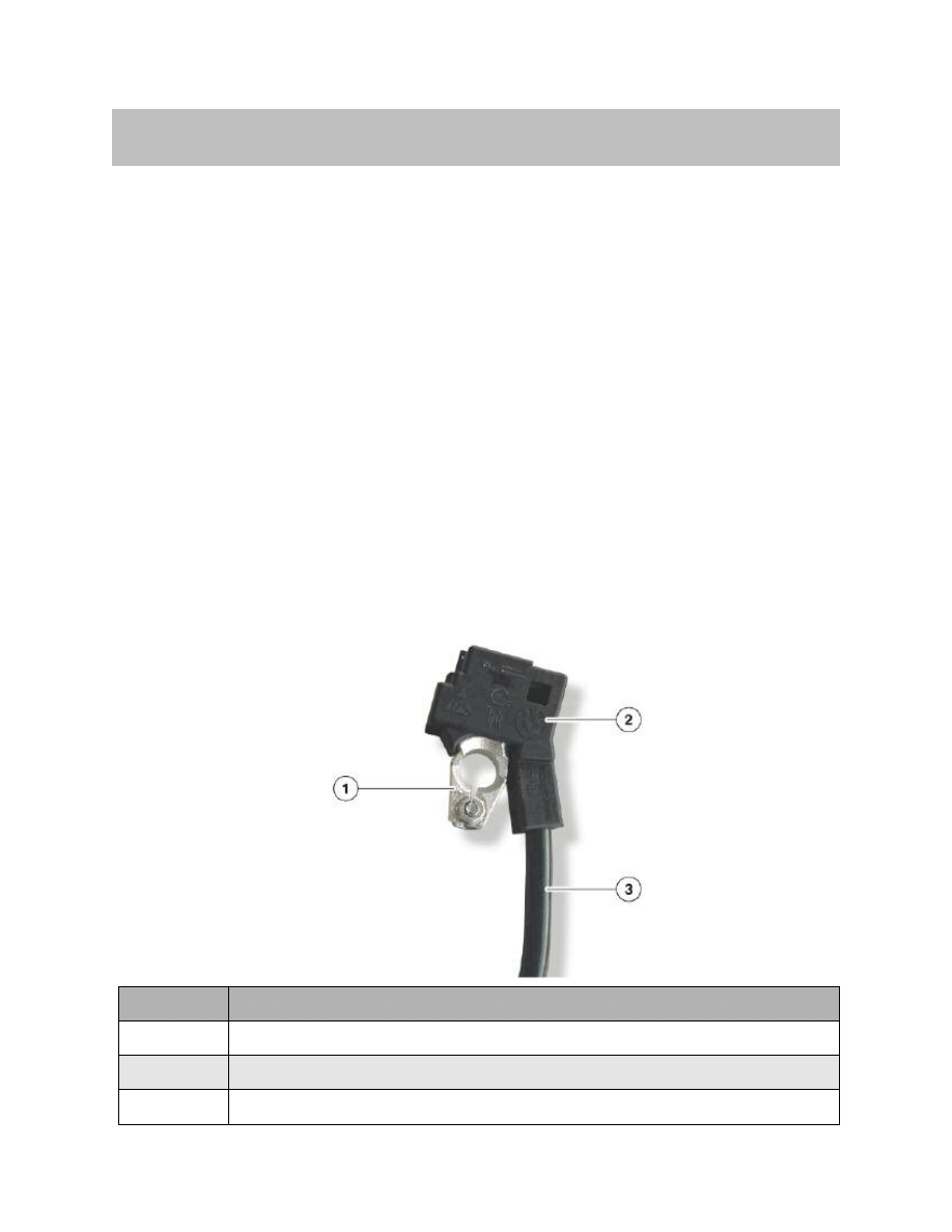
System Components
Index
Explanation
1
Battery negative terminal
2
IBS
3
Battery negative lead
The intelligent battery sensor (IBS) is a mechatronic component for monitoring the
battery condition. The description “intelligent” indicates that the IBS has an integral
microprocessor. That microprocessor performs the computation and assessment of
time-critical measured variables.
The power supply for the IBS is provided by a separate lead from the power distribution
box on the battery. The data from the IBS is passed to the higher-level control units
(DME) via the LIN bus. If necessary, the IBS can wake up the Junction box module via a
separate lead.
24
F01 Energy Management
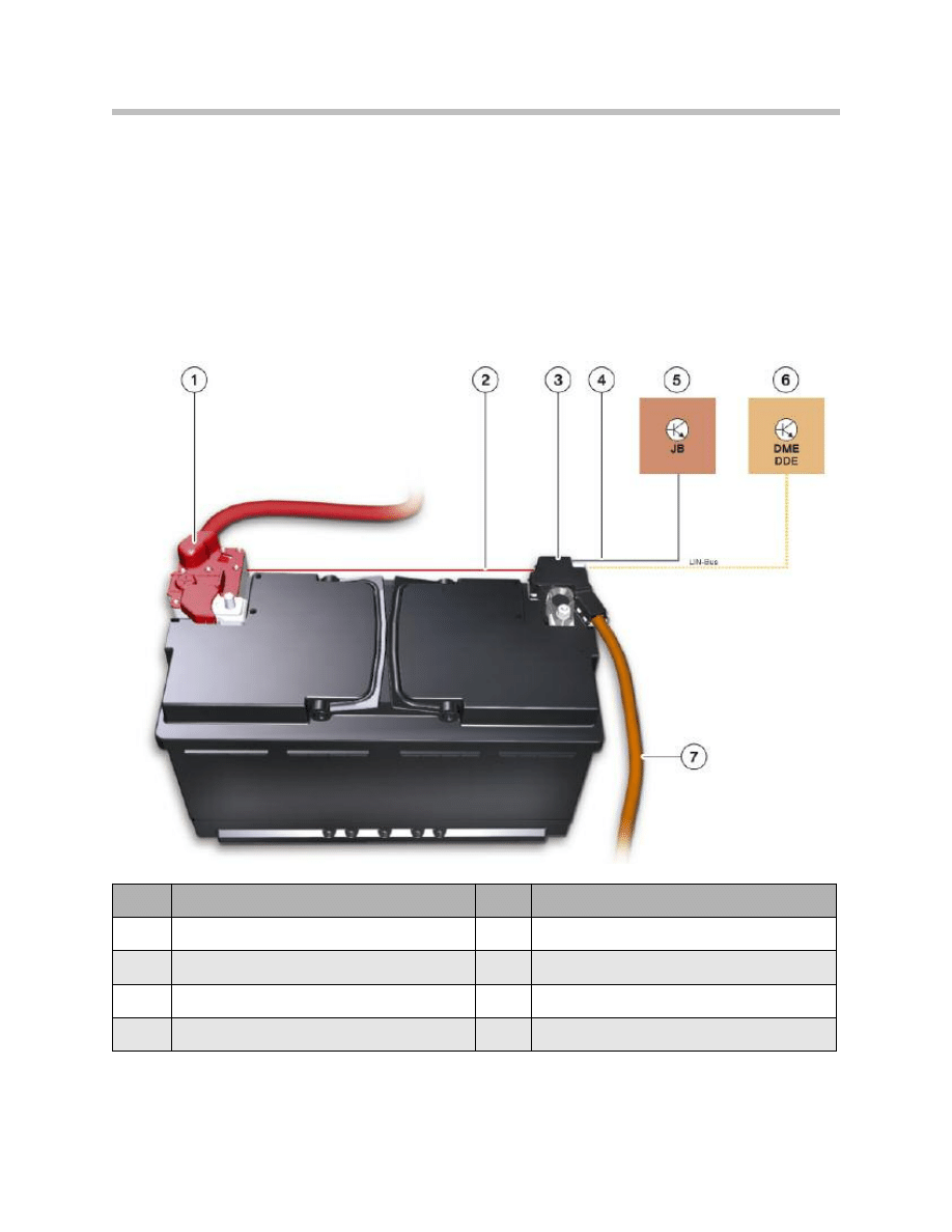
Index
Explanation
Index
Explanation
1
Battery positive lead
5
Junction box module
2
Power supply for IBS
6
ECM (DME)
3
IBS
7
Battery negative lead
4
Wake-up line
LIN
Local Interconnect Network bus
IBS in vehicle network

The following physical battery variables are registered by the IBS:
• Current
• Voltage
• Terminal temperature.
Among other things, the following main functions are integrated in the IBS:
• Continuous measurement of the battery current, voltage and temperature under all
vehicle operating conditions.
• Calculation of the battery indicators as the basis for the charge and health status of
the battery. The battery indicators are charge and discharge current, voltage and
temperature of the vehicle battery. Alongside calculation of the battery indicators,
preliminary computation of the battery charge level (“state of charge”, SOC) is also
carried out.
• Balancing of the charge/discharge current of the battery.
• Continuous monitoring of the battery charge status and making available the corre-
sponding data in the event of insufficient battery power.
• Calculation of the current progression when starting the engine to determine the
battery health status.
• Closed-circuit current monitoring of the vehicle.
• Self-diagnosis
Wake-up Function
When the vehicle is in idle mode, the IBS continuously records the data relevant to the
battery indicators. The IBS is programmed to wake up every 14 seconds in order to
update the measured data by taking new readings. The time required to take the read-
ings is approximately 50 milliseconds. The measured data is stored on the IBS in the
memory for recording the closed-circuit current.
The wake-up function applies only when the vehicle is in idle mode. If the IBS detects a
wake-up trigger, the Junction box module is woken up by a PWM signal. The IBS is
directly connected to the Junction box module via a separate lead.
The pulse duty factor indicates the reason for the wake-up:
25
F01 Energy Management
Pulse duty factor
Reason for wake-up
20%
Starting capacity, limit 1
40%
Starting capacity, limit 2
60%
Raised closed-circuit current

26
F01 Energy Management
A wake-up due to raised closed-circuit current can take place up to three times.
Depending on the vehicle status and reason for the wake-up, the Junction box module
performs one of the following actions:
• Wakes up the vehicle so that the DME can send shut-down commands to
electrical devices that are operating while the vehicle is in parked mode
• Resets Terminal 30F (without waking up the vehicle)
• Switches off Terminal 30F (without waking up the vehicle).
A fault memory entry is registered in each case.
Commissioning
The IBS is fully functional as soon as it has been fitted to the battery terminal (screwed to
the grounding point and connected to the signal leads), i.e. it can immediately detect the
basic variables, current, voltage and temperature.
However, the variables derived from those readings for the purposes of power manage-
ment, i.e. battery condition, starting capacity, etc., must first be recalculated and, there-
fore, there is a time lag before they are available.
When the engine is restarted, the DME reads off the closed-circuit current progression. If
it diverges from the defined closed-circuit current progression, a fault is registered in the
DME fault memory.
In the period between “Engine OFF” and when the DME main relay is switched off, the
IBS is informed by the DME as to the maximum charge that can be drawn from the bat-
tery on the basis of ensuring that the engine can be reliably restarted. After the DME
main relay is switched off, the IBS continually checks the battery charge level (SOC) and
the closed-circuit current.
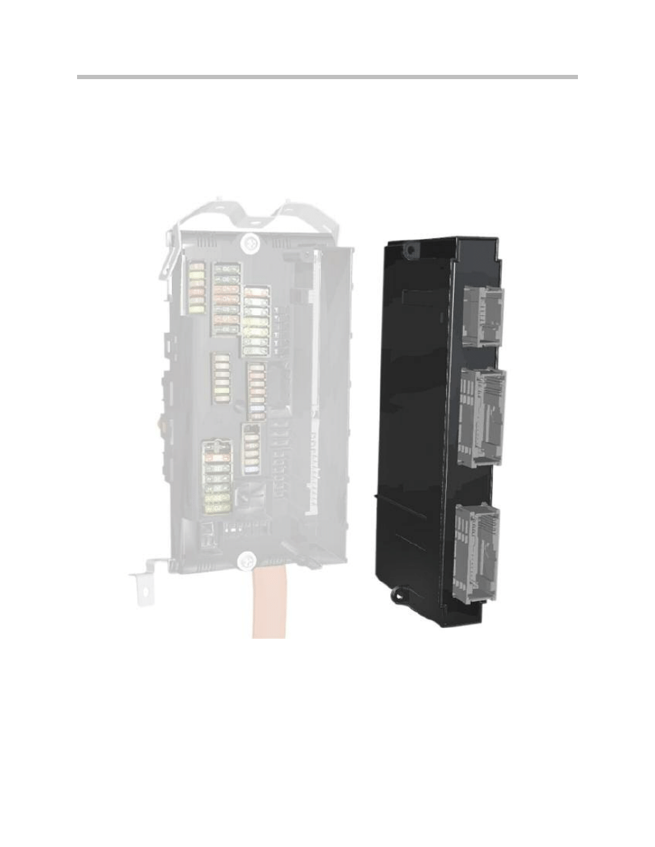
Junction Box Module
The Junction box module (JBE) is responsible for switching the Terminal 30F relay and
for storing information (history data and fault memory entries) related to energy manage-
ment. As part of vehicle diagnostics, these data can be used to evaluate faults and to
analyse the vehicle battery.
Engine Management (Power Management)
The (power management) software for controlling the energy balance is located in the
engine management. On the basis of that control algorithm, various electrical devices in
the vehicle’s electrical system are switched off by the CAS control unit via the Terminal
30B relay or by the Central Gateway Module and engine management module via the
Terminal 30F relay. The power management is additionally responsible for evaluating and
storing the IBS data.
27
F01 Energy Management
Transport Mode
Indication of Battery Condition
The batteries in vehicles coming off the production line are adequately charged so that
SOC > 80% (SOC = “State of charge”). However, since several days or weeks can pass
between the time the vehicle comes off the production line and when it is delivered to
the customer, the battery will have discharged to a greater or lesser degree. Therefore,
every battery must be charged according to the recharging calendar.
The F01/F02 is the first model on which it is possible to display the charge level of the
battery when the new car is being transported. When production or transport mode is
activated, a Check Control message is generated that provides a quick indication of the
battery condition.
Note: If the SOC has dropped to less than 35%, the indication continues to be
displayed on the instrument cluster until the battery is replaced and a
change of battery is registered.
Note: When transport mode is reset, there is no indication on the instrument
cluster of the battery charge level.
Note: If the vehicle is delivered with the red Check Control message “Battery
charge level very low” active, it is essential that the low battery charge
is recorded as transport damage on the delivery note.
28
F01 Energy Management
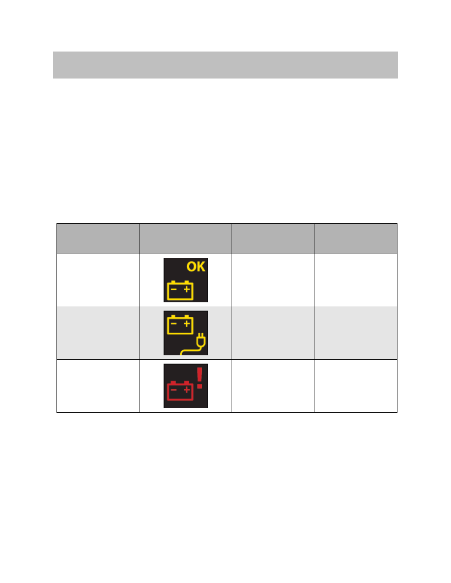
Service Information
Battery condi-
tion
Display on
instrument cluster Audible signal
Action
Battery condition OK
SOC 60% to 100%
No sound
No action necessary.
Battery is discharged.
SOC 35% to 60%
No sound
Charge battery.
Battery charge level is
very low.
SOC less than 35%
Double gong
Replace battery.

In such cases, the test module “Energy diagnosis” must be carried out to establish the
cause. Replace the battery before handing over the vehicle to the customer and register
the change of battery using the service function.
Note: If a vehicle is delivered with the yellow Check Control message “Charge
battery”, this should also be recorded on the delivery note. The battery
must then be charged once and an energy diagnosis carried out.
29
F01 Energy Management

Functions switched off/modified in transport mode
On the F01/F02, the following functions are switched off/on in transport mode:
= Function is switched off
= Function is switched on or changed.
30
F01 Energy Management
Index
Function
Control unit Transport mode
1
Mirror heating High (driver's/front passenger's door)
FRM
2
Home lighting
FRM
3
Welcome light
FRM
4
Daytime lights (bar can no longer be activated once vehicle has
travelled more than 60 km)
FRM
5
Side lights in switch position “A” + “2” (at Terminal 15 OFF)
FRM
6
Parking light (at Terminal 0)
FRM
7
Turning lights
FRM
8
Adaptive headlights
FRM
9
Main beam assistant
FRM
10
Limitation of load shut-down time from 8 minutes to 1 minute
(vanity mirrors, reading lights, interior lights are also switched off)
FRM
11
Pre-sleep mode, i.e. raised closed-circuit current when vehichle
not locked for cyclic scanning of steering column and light selector
switch; deactivated 1 minute after Terminal R OFF.
FRM
12
Power window (rear driver’s side)
JB
13
Power window (rear passenger’s side)
JB
14
Headlight washer system (SRA)
JB
15
Seat heating Low (driver/passenger, front and rear)
JB
16
Washer-jet heating
JB
17
Mirror heating Low (driver/passenger)
JB
18
Terminal 30F isolation after programmable period: Isolation gener-
ally occurs 1 minute after Terminal 30B OFF regardless of lock
status.
JB
19
Electric sunblinds (middle, left/right)
JB
20
Output of Check Control message “TRAMODE” when transport
mode set.
JB
21
Radio remote control (open/double-lock vehicle) Radio remote
control only usable in transport mode when CAS active. To wake
vehicle from sleep mode to use radio remote control, tailgate but-
ton must be pressed -> Bus awake -> Radio remote control active.
CAS

31
F01 Energy Management
Index
Function
Control unit Transport mode
22
Radio remote control, open tailgate
Reason: transport damage to tailgate on train or truck due to inadver-
tent opening of tailgate by pressing radio remote control.
CAS
23
Limitation of Terminal 30B time from 30 min/60 min to 5 min
CAS
24
Reduction of Terminal R active time from 8 minutes to 1 minute
regardless of whether door switch operated
CAS
25
Immediate switch from Engine Off to Terminal 0when Start/Stop but-
ton held pressed and when quickly pressed and released
CAS
26
Comfort Access, complete function
CAS
27
Slide/tilt sunroof FZD 8 28 DWA function
FZD
29
Read outside temperature sensor or cyclic query in vehicle idle mode
Kombi
30
Coolant temperature request from DME
Kombi
31
Clock function for aux. heating and aux. ventilation functions
Kombi
32
Set fault memory bar (excluding transport mode fault memory and
high/low voltage fault memory
Kombi
33
Tailgate lift
HKL
34
Steering wheel heating
SZL
35
Seat heating (driver/passenger) SM 8
36
Seat adjustment, passenger
ISM
37
Seat adjustment, rear
ISM
38
Lumbar support
ISM
39
Active seat ventilation
ISM
40
Active seat
ISM
41
Rear window defogger
IHKA
42
Blower; limitation to max. 50%
Caution: if DEFROST button pressed > no limitation i.e.
100% blower output possible.
IHKA
43
Defrost function (100% fan power possible)
IHKA
44
Compressor coupling closed so disconnected from power
IHKA
45
Electric auxiliary heater (PTC)
IHKA
46
Residual heat function
IHKA
47
Auxiliary ventilation function
IHKA
48
Independent ventilation function
IHKA
49
PATT module
IHKA
50
Run-on of interior temp. sensor fan from Terminal R Off
IHKA

32
F01 Energy Management
Index
Function
Control unit Transport mode
51
Air vent positioning immediately after Terminal R OFF
(due to Term. 30B + Term. 30F switching off)
IHKA
52
Aux. coolant pump and valve
IHKA
53
Rear fan; (total shut-down)
FKA
54
Rear PTC, left/right
FKA
55
Rear A/C control panel
FKA
56
Rear A/C fan; (total shut-down)
HKA
57
Flap setting
HKA
58
Head unit MOST active, unusable, no display, no entertainment sys-
tem output; nevertheless, sound output from PDC; \
Diagnosis of MOST control units possible;
MOST devices "not functioning": Top HiFi, CDC, DVD changer, ULF-
SBX, SDARS/IBOC, RSE
CIC
59
HiFi amplifier, audio output
Top HiFi
60
Central information display, front
CID
61
Central information display, rear
FD
62
Video switch, video output and reception
VSW
63
Controller, rear Controller
CON/FCON
64
Bluetooth interface
ULF-SBX
65
Telematics function
TCU
66
Emergency call function
TCU
67
Telephone control, prevent wake-up of MOST bus
TCU
68
Night Vision
NVE
69
HUD (Head-up display)
HUD
70
All cameras
KAFAS
71
Ride height monitoring and levelling during overrun
EHC
72
Power supply to wheel satellites for VDC
VDM
73
ARS valves (5 in total)
VDM
74
ACC (heater, camera)
ICM
75
Power supply for RDC transmitter/function
RDC
76
Speed limitation to 4500 rpm
DME
77
Idle speed boost (upper idle speed value)
DME
78
Maximum charging voltage (+14.8 V to 40 °C)
DME
79
Deactivating IGR function
DME
80
Battery charge indication by CCM
DME
Closed-circuit Current
Upwards of a closed-circuit current level of 80 mA, a Check Control message is generat-
ed (raised battery discharge rate when parked).
Note: The closed-circuit current should always be measured if increased cur-
rent consumption is suspected. Even power consumption levels only
slightly above normal can cause relatively rapid battery discharge.
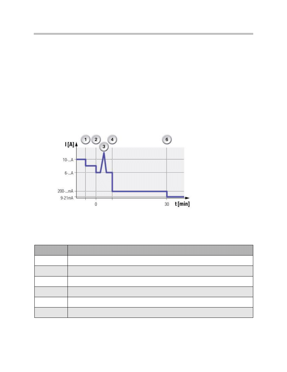
The graph below shows the typical closed-circuit current progression on the F01/F02
associated with the various electrical system statuses. The actual current values change
depending on the vehicle equipment configuration.
The terminal “load shut-down” (e.g. reading or 60 minutes with) light and vanity mirror
light) is switched off corresponding to the terminal status.
33
F01 Energy Management
Typical closed-circuit current progression for double-locked vehicle on F01/F02
Index
Explanation
1
Terminal 15N off
2
Terminal R off
3
Vehicle is secured (locked)
4
Start of bus rest phase
5
Electrical load shutdown after 8 minutes
6
KL30 B OFF (30 minutes w/o phone or 60 min with)
Load shut-down switches off immediately when the vehicle is secured. In all other termi-
nal statuses, the load shut-down terminal is switched off after an overrun period of 8 min-
utes. It is activated by the footwell module.
Electrical System and Battery Diagnosis
Over the past few years, the energy management of all BMW models has been continu-
ously improved and standardized across the various model series. In terms of energy
diagnosis, this also means standardization of testing schedules and displays in the BMW
diagnostic system.
The aim of the diagnostic procedures is to show the causes of a discharged battery as
unambiguously as possible. In view of the complexity, especially in the area of energy
management, the specific cause of a fault can be shown only partially depending on its
nature. The acquired energy diagnosis data are shown if the fault cannot be clearly
assigned based on the acquired data.
Power management is retained in full while the expanded diagnostic options are now resi-
dent in the history memory.
ZGM monitors the vehicle status, registers inhibited sleep mode or unauthorized wake-up
after Terminal 30B is switched off and requests a reset or shut-down of Terminal 30F by a
bus message to the JBE.
The originator and reason for wake-up (unauthorized wake-up) are stored as additional
information in the ZGM fault memory. The driving profile for the last 5 weeks is stored in
the JBE energy history memory. The energy history memory is referred to for energy
diagnosis purposes.
34
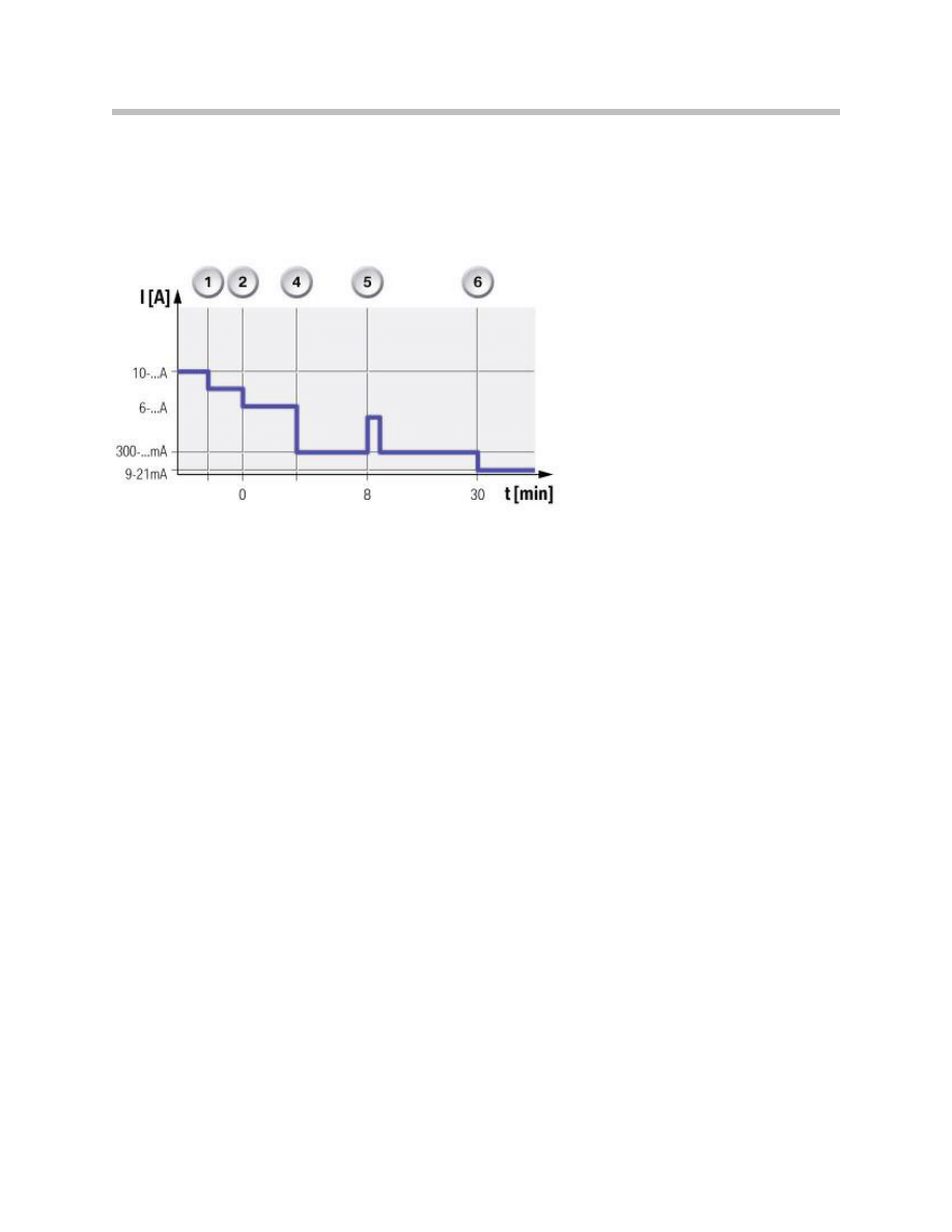
F01 Energy Management
Typical closed-circuit current progression for unlocked vehicle on F01/ F02
Document Outline
- Main Menu
- 01_F01 Introduction
- 02_F01 Powertrain
- 03_F01 Voltage Supply & Bus Systems
- 03.1_F01 Bus Systems
- 03.2_F01 Voltage Supply
- 03.3_F01 Energy Management
- 03.4_F01 Car Access System 4
- 04_F01 Chassis Dynamics
- 04.1_F01 Chassis and Suspension
- 04.2_F01 Dynamic Driving Systems
- 04.3_F01 Longitudinal Dynamics Systems
- 04.4_F01 Lateral Dynamics Systems
- 04.5_F01 Vertical Dynamics Systems
- 04.6_F01 Cruise Control Systems
- 05_F01 General Vehicle Electronics
- 05.1_F01 Comfort Access
- 05.2_F01 Central Locking System
- 05.3_F01 Automatic Soft Close
- 05.4_F01 Power Windows
- 05.5_F01 Sliding Tilting Sunroof
- 05.6_F01 Anti-theft System
- 05.7_F01 Automatic Luggage Compartment Lid
- 05.8_F01 Exterior Lighting
- 05.9_F01 Interior Lighting
- 05.10_F01 Wiper-Washer System
- 05.11_F01 Exterior Rear View Mirrors
- 05.12_F01 Seats
- 05.13_F01 Steering Column Switch Cluster
- 06_F01 Driver Information Systems
- 06.1_F01 Displays Indicators and Controls
- 06.2_F01 Head-up Display
- 06.3_F01 BMW Night Vision 2
- 06.4_F01 Active Blind Spot Detection System
- 06.5_F01 KAFAS
- 06.6_F01 PDC-TRSVC
- 07_F01 Information and Communication Technology
- 07.1_F01 Rear Seat Entertainment Systems
- 07.2_F01 Telephone System
- 07.3_F01 Voice Activation System
- 07.4_F01 Audio Systems
- 08_F01 Climate Control
- 09_F01 Passive Safety Systems
- 10_F01 Service Information
- 10.1_F01 System Functions
- 10.2_ISTA-Programming
Wyszukiwarka
Podobne podstrony:
PBO G 03 F01 Drill records of Contingency plan ships
DESIGN OF HYBRID PHOTOVOLTAIC POWER GENERATOR, WITH OPTIMIZATION OF ENERGY MANAGEMENT
2003 03 personalize your management development
03 2 F01 Voltage Supply
03c E70 Energy Management
03 1 F01 Bus Systems
08 PAW 5 6 Management Review Process Assessment Worksheet Rev 1 1 03
PBO G 08 F01 The minutes of management review
07 DFC 5 6 Management Review Process Rev 1 1 03
Fleet Management System FMS WSM 19 03 11 pl(1)
06 SOP 5 6 Management Review Rev 1 1 03
Can we accelerate the improvement of energy efficiency in aircraft systems 2010 Energy Conversion an
Karmy Royal canin Special Club Special Club Pro Energy HE Royal Ocena 03 na 20
okładka na cd Energy 2000 – Junior Party (03 07 11 Aras,Matt G ,Hubert S ,Thomas )Niedziela
Customizing the Microsoft Management Console 03 2007
OKŁADKA NA CD;Energy 2000 (Katowice) – Eddy Wata (10 03 2012) SOBOTA
03 Sejsmika04 plytkieid 4624 ppt
03 Odświeżanie pamięci DRAMid 4244 ppt
więcej podobnych podstron