
On Comparing Noise Output Powers Of Amplifiers With Simple Equipment
And
A Simple Way To Calculate Noise Figure Using An Amplifier With A
Calibrated Noise Figure
Dallas Lankford, 1/11/2011, rev. 10/1/2011
Wide null aperture, low signal output, MW arrays like the DDFA and QDFA (see
), and compact
rotatable, top band (160 meter band), high RDF, low signal output, dual flag arrays, like the WF, Big WF, Giant WF,
and HWF (see
), require a preamp with as low as possible noise figure as the preamp (or first
preamp in the preamp cascade). Noise figures of about 1.0 dB or less are necessary for best weak signal performance
with these kinds of antenna arrays. Such preamps are not “off the shelf” items, and have only recently been developed
for the MW band and top band. As a matter of fact, the development is still ongoing. Because of this, it seems
appropriate to make available current information on these developments even though that information is subject to
change. This article provides some of that information.
The noise power output N(dBm) of an amplifier in dBm is
N(dBm) = 10 log(F ) + 10 log(G) +10 log(B) – 174 = NF + 10 log(G) +10 log(B) – 174
where F is the amplifier's noise factor, G is the amplifier's gain, and B is the noise power bandwidth in Hertz of the
noise power measuring system, and NF is the noise figure of the amplifier.
The formula above assumes that the input impedance of the amplifier is real and equal to the value of the thermal
noise source resistor.
Neither the noise factor nor the noise figure of an amplifier are easy to measure accurately. However, an amplifier has
a definite noise factor which does not change with time. The power bandwidth of a noise power measuring system is
not easy to measure accurately. However, a noise power measuring system has a definite noise power bandwidth
which does not change with time. Generally two amplifiers constructed from two different schematics will not have
the same noise factor or gain. Let the subscripts 1 and 2 denote the two amplifiers. If the same measuring system is
used in both cases, and the noise power bandwidth is not changed, then
N
1
(dBm) – 10 log(F
1
) – 10 log(G
1
) = N
2
(dBm) – 10 log(F
2
) – 10 log(G
2
),
which can be algebraically rearranged to
[N
1
(dBm) – N
2
(dBm)] – [10 log(G
1
) – 10 log(G
2
)] = 10 log(F
1
) – 10 log(F
2
) = NF
1
– NF
2
.
If G
1
≥ 25.12 (14 dB) , G
2
> G
1
, and amplifier 1 is cascaded with a third amplifier with the same noise figure as
amplifier 1 but with gain 10 log(G
2
) – 10 log(G
1
), then the gain of the cascade G
c
is
G
c
= G
2
, and it can be shown that
NF
1
= 0.16 + NF
2
, so that
[N
c
(dBm) – N
2
(dBm)] – [10 log(G
c
) – 10 log(G
2
)] = NF
c
– NF
2
, from which is follows that
[N
c
(dBm) – N
2
(dBm)] – [10 log(G
2
) – 10 log(G
2
)] = 0.16 + NF
1
– NF
2
, or
[N
c
(dBm) – N
2
(dBm)] = 0.16 + [N
1
(dBm) – N
2
(dBm)] – [10 log(G
1
) – 10 log(G
2
)], so that
N
c
(dBm) = 0.16 + N
1
(dBm) + [10 log(G
2
) – 10 log(G
1
)].
1
If N
c
(dBm) and N
1
(dBm) differ by 1 dB or more, then
N
c
(dBm) ≈ N
1
(dBm) + [10 log(G
2
) – 10 log(G
1
)]
with an error of no more than 20% for 14 dB or greater gain (no more than 3% for 22 dB or greater gain as in
Example 1 and Example 2 below), and when G2 > G1 , and so N
c
(dBm) is greater than N
1
(dBm) by approximately
10 log(G
2
) – 10 log(G
1
) .
In other words, the cascaded noise N
c
(dBm) is the “normalized” noise of amplifier 1 (by mathematically adjusting the
gain of the cascade to be the same as amplifier 2). If the normalized noise N
c
(dBm) of amplifier 1 is greater than the
noise N
2
(dBm) of amplifier 2, then amplifier 1 has poorer noise performance on weak signals than amplifier 2 by
N
c
(dBm) – N
2
(dBm). If equal, then they have equal performance. If the normalized noise N
c
(dBm) of amplifier 1 is
less than the noise N
2
(dBm) of amplifier 2, then amplifier 1 has better noise performance on weak signals than
amplifier 2 by N
c
(dBm) – N
2
(dBm).
The test frequency for all of the following examples was 1.9 MHz unless otherwise stated.
Example 1: The noise output power of a 23 dB gain BF981 with high Q LC tuned circuit front end resonant at 1.83
MHz was measured as – 102 dBm while the noise output power of two cascaded 14 dB NIL amplifiers (28 dB gain
total) was measured as – 97 dBm. The gain difference was 5 dB, from which 5 + (– 102) = – 97 dBm, so the
amplifiers have virtually identical weak signal amplifier noise output performance. It is assumed that the noise
powers are measured sufficiently far above the measuring receiver noise floor so that inaccuracies due to the receiver
noise floor are not introduced. In this case, the measuring receiver was a Perseus preceded by a 10.8 dB gain push-
pull Norton transformer feedback amplifier. The Perseus meter was operated in maximum averaging mode, and the
BF981 was shielded from external RF with all ports blocked by high attenuation common mode chokes. Without the
common mode chokes, external noise ingress was obvious. The input impedance of the BF981 amplifier was not
matched to the source, so the BF981 numbers above may be different if the impedances are matched.
Example 2: The noise output power of a 22 dB gain W7IUV amplifier was measured as –99 dBm while the noise
output power of two cascaded 14 dB NIL amplifiers (28 dB total gain) was measured as –97 dBm. The gain
difference was 6 dB, from which 6 + (–99) = –93, so the two NIL amplifiers cascade (as well as the BF981 amplifier)
has a 4 dB noise power output advantage over the W7IUV
amplifier. I believe that this advantage was observed
recently by NX4D as he was comparing a N4IS amplifier
using 6 paralleled BF981's with a cascade of two W7IUV
amplifiers connected to his (dual) rotatable GWF flag
array listening to European CW on top band.
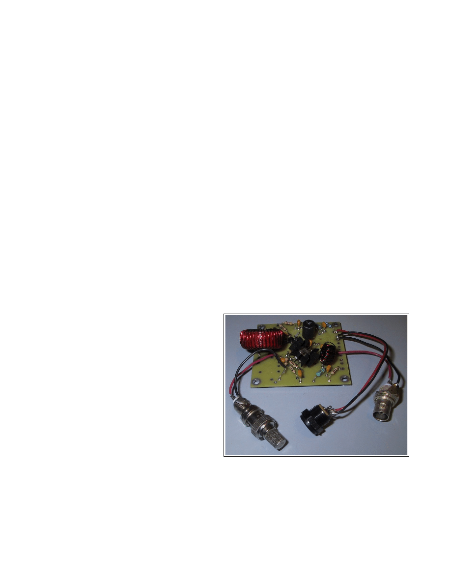
At right are the two amplifiers, a BF981 amplifier and a
W7IUV amplifier. They were constructed on the same
PC board, a PC board originally developed for push-pull
MRF581A Norton transformer feedback amplifiers. The
BNC input and output are moved from one amplifier to
the other for measurements. An air variable capacitor
which was used to tune the BF981 amplifier to 1.83 MHz
is not shown.
Example 3: A 10.4 dB gain standard push-pull Norton
transformer feedback amplifier with MRF581A's was
compared to a 11.0 dB gain push-pull Mini-Norton
transformer feedback amplifier with calibrated NF from Jack Smith of Clifton Laboratories. The noise power output
of the standard Norton was 0.3 ± 0.2 dB less than the Mini-Norton. Using the formula
[N
1
(dBm) – N
2
(dBm)] – [10 log(G
1
) – 10 log(G
2
)] = NF
1
– NF
2
it follows that
– 0.3 – (10.4 – 11.0) = NF
1
– NF
2
.81
2
To help avoid mistakes, let NF
N-MRF581A
= NF
1
and NF
MiniN
= NF
2
. From the above we have
NF
N-MRF581A
– NF
MiniN
= – 0.3 – (10.4 – 11.0) = 0.3 (± 0.2).
The Clifton Laboratories Mini-Norton has a calibrated
noise figure of about 1.4 dB ± 0.2 dB at 10 MHz.
Assuming the Mini-Norton NF at 1.9 KHz is also 1.4 dB
± 0.2 dB , it follows that
NF
N-MRF581A
= 1.7 dB (± 0.4 dB).
A photo of the Mini-Norton is given at right.
Example 4: The the NF of a single BF981 was
measured as 2.1 dB. This is an improvement over the
4.7 dB NF preamps which some people have used, but
there are better choices for use with dual and quad flag arrays, namely my LIN with 0.9 dB NF or one of Clifton
Laboratories Norton amplifiers with a 1.4 dB NF. A 6x BF981 preamp was originally stated to have a NF of less than
1.0 dB, but that number was later amended to 1.4 dB. However, if the input impedance was not matched to the
source, then the 1.4 dB value is incorrect, and the NF of the 6x BF981 is probably closer to the 2.1 dB of the single
BF981.
Example 5: The NF of a 22 dB gain W7IUV amplifier was measured as 4.7 dB. As discussed in Example 2, the
W7IUV amplifier is not suitable for top band WF arrays. It is also not suitable for DDFA and QDFA MW arrays.
Example 6: A 13.4 dB gain LIN transformer feedback amplifier with MRF581A BJT's was compared to a 10.9 dB
gain (sometimes my system measures it as 11.0, sometimes 10.9, here 10.9 will be used) push-pull Mini-Norton
transformer feedback amplifier with calibrated NF which has been developed recently by Clifton Laboratories. The
noise power output of the LIN was 2.0 dB greater than the Mini-Norton. Similar to Example 3 it follows that
NF
LIN-MRF581A
– NF
MiniN
= 2.0 – (13.4 – 10.9) = – 0.5 so that
NF
LIN-MRF581A
= 0.9 dB (± 0.4 dB).
The intercepts of the LIN-MRF581 are about as high as a standard push-pull Norton transformer feedback amplifier,
namely IIP3 = +32 dBm and IIP2 = +82 dBm. Both the LIN and standard Norton draw 16 mA per MRF581A. The
3
rd
order intercepts of the N4IS amplifier are estimated to be about +10 dBm based on measured analogous 2 meter
amplifiers. This should not be a problem because the signal level outputs of the WF antennas it is used with are low.
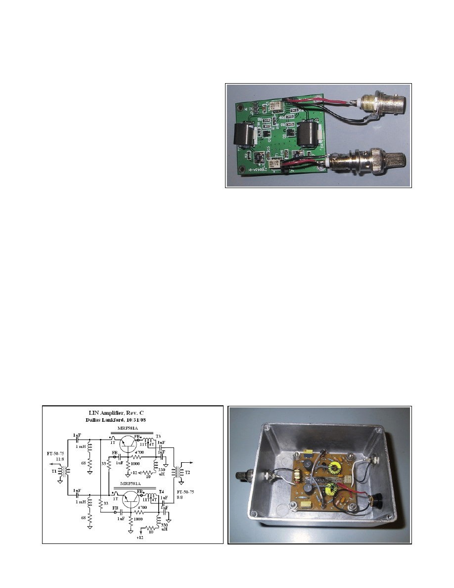
A schematic of the LIN amplifier is given below, followed by a photo of its PC board. The original LIN did not have
the 33 ohm resistor and FB for parasitic prevention (although no parasitics were ever observed without them).
3

Example 7:
A 13.4 dB gain Clifton Laboratories LIN-Z10042A transformer feedback amplifier with NE85634A
BJT's was compared to a 10.9 dB gain (sometimes my system measures it as 11.0, sometimes 10.9, here 11.0 will be
used) push-pull Mini-Norton transformer feedback amplifier with calibrated NF which has been developed recently by
Clifton Laboratories. The noise power output of the LIN-Z10042A was 4.0 dB greater than the Mini-Norton. Similar
to Example 3 it follows that
NF
LIN-Z10042A
– NF
MiniN
= 4.0 – (13.4 – 11) = 1.6 so that
NF
LIN-Z10042A
= 3.0 dB (± 0.4 dB).
This measurement was done after Jack Smith of Clifton Laboratories reported substantially higher NF's for a LIN-
Z10043A at 10 MHz and above. It appears that the Z10042A and Z10043A NF's increase substantially after doing
the LIN mod. The NF of a LIN-MRF581A was subsequently measured at 10.75 MHz and found to be 0.9 dB (+/- 0.4
dB). There are circuit differences between the LIN-Z10042A / LIN-Z10043A and the LIN-MRF581A amplifiers as
well as different BJT's which may explain why the LIN mod which was done on those two Clifton Laboratories
amplifiers did not reduce their noise figures.
Acknowledgment
I would like to express my appreciation to Jack Smith, K8ZOA of Clifton Laboratories for sending me a Mini-Norton
amplifier with a calibrated NF, for many helpful discussions about noise figure measurement and other matters, and
for correcting a terrible mistake which I made in an earlier version of this article. Of course, I alone am responsible
for any remaining mistakes in this article.
4
Wyszukiwarka
Podobne podstrony:
A comparative study on conventional and orbital drilling of woven carbon
[2006] Application of Magnetic Energy Recovery Switch (MERS) to Improve Output Power of Wind Turbine
Comparative testing and evaluation of hard surface disinfectants
32 425 436 Ifluence of Vacuum HT on Microstructure and Mechanical Properties of HSS
On demand access and delivery of business information
Effect of heat treatment on microstructure and mechanical properties of cold rolled C Mn Si TRIP
Compare and contrast literature of Whitman and Dickinson in terms of God, man and nature
Speculations on the Origins and Symbolism of Go in Ancient China
J Justeson, T Kaufman A Newly Discovered Column in the Hieroglyphic Text on La Mojarra Stela 1 A Te
diffusion on innovations through social networks of children
effects of kinesio taping on the timing and ratio of vastus medialis obliquus and lateralis muscle f
On the definition and classification of cybercrime
GASTR DEL SOL Harp Factory on Lake Street CD (Table of the Elements) SWC019swc019
the effect of sowing date and growth stage on the essential oil composition of three types of parsle
On Will and the Practice of Will Thelema101
1948 On the stability and instability of shock waces Thomas
[2006] Application of Magnetic Energy Recovery Switch (MERS) to Improve Output Power of Wind Turbine
Roger Bacon Tract on the Tincture and Oil of Antimony
więcej podobnych podstron