
Initial Print Date: 01/09
Table of Contents
Subject
Page
New Chassis Systems for F01/02 . . . . . . . . . . . . . . . . . . . . . . . . . . . . . . .3
Chassis and Suspension Comparison . . . . . . . . . . . . . . . . . . . . . . . . . . . .4
Cast aluminium spring support (body side) . . . . . . . . . . . . . . . . .12
Kinematics and elastokinematics . . . . . . . . . . . . . . . . . . . . . . . . . .14
New challenge for the integral rear axle . . . . . . . . . . . . . . . . . . . .15
Arm arrangement, E65 integral IV rear axle . . . . . . . . . . . . . . . . .17
Arm arrangement, integral-V rear axle in the F01/F02 . . . . . . . . .18
Damping/suspension . . . . . . . . . . . . . . . . . . . . . . . . . . . . . . . . . . . . . . .20
Extended Hump rims (EH2+) . . . . . . . . . . . . . . . . . . . . . . . . . . . . .24
RSC tires with emergency running properties . . . . . . . . . . . . . .25
F01/F02 Wheel sizes . . . . . . . . . . . . . . . . . . . . . . . . . . . . . . . . . . . .25
F01 Chassis and Suspension
Revision Date:

2
F01 Chassis and Suspension
Chassis and Suspension
Model: F01/F02
Production: From Start of Production
After completion of this module you will be able to:
• Understand the differences between the Integral IV and V rear axle.
• Understand the differences between chassis components and systems
on the F01 as compared to the E65.

Through intelligent design layout and optimum package space utilization on the new
F01/F02, the basis has been created for distinctly increasing the driving dynamics while
improving comfort and vehicle handling.
At virtually identical wheel loads, a greater track width and a larger wheelbase have been
realized compared to the predecessor, the E65.
The development of the new generation chassis and suspension systems in the new
F01/F02 focused on revolution instead of evolution. The aim was to set a new bench-
mark.
The lightweight construction philosophy was consistently pursued in the design of the
chassis and suspension systems. This is reflected in the widespread use of aluminum,
representing an important contribution to increasing comfort and reducing CO2 emis-
sions.
For the first time, a BMW Sedan is fitted with a double wishbone front axle made of alu-
minum, a steerable integral-V rear axle, BMW integral active steering (IAL) and the innov-
ative damper system, the 2nd generation vertical dynamics control (VDC 2).
The integrated chassis management (ICM) intelligently links all chassis and suspension
control systems, thus achieving a new level of functional quality. Further highlights
include "Dynamic Drive" (ARS) and a fully variable power steering pump to improve fuel
economy.
3
F01 Chassis and Suspension
New Chassis Systems for F01/02
Explanation
E65
F01
E66
F02
Overall length
5039 mm
5072 mm
5179 mm
5212 mm
Wheelbase
2990 mm
3070 mm
3130 mm
3210 mm
Overhang, front
914 mm
864 mm
914 mm
864 mm
Overhang, rear
1135 mm
1138 mm
1135 mm
1138 mm
Vehicle Width
1902 mm
1902 mm
1902 mm
1902 mm
Front track width
(basic wheel)
1578 mm
1612 mm
1578 mm
1612 mm
Rear track width
(basic wheel)
1596 mm
1646 mm
1596 mm
1646 mm

Chassis and Suspension Comparison
4
F01 Chassis and Suspension
Comparison
E65/E66
F01/F02
Front Axle
Doble pivot spring strut front axle
Double wishbone front axle
Suspension/damping, front
Steel spring/EDC
Steel spring/VDC 2
Stabilizer bar, front
Passive or Active (ARS)
Passive or Active (ARS)
Rear axle
Integral IV
Integral V
Suspension/damping, rear
Steel spring or Air spring/EDC
Steel spring or Air spring (VDC2)
Stabilizer bar, rear
Passive or Active (ARS)
Passive or Active (ARS)
Brake, front
Disc brake with rotor diameter of 348mm Disc brake with rotor diameter of 373mm
Brake, rear
Disc brake with rotor diameter of 345mm Disc brake with rotor diameter of 368mm
Parking brake
Drum brake with EMF
Drum brake with EMF
Wheels/tires
Standard tires
Runflat tires (as standard)
Steering
Power steering (w /Servotronic)
Power steering with Servotronic
(optional IAL)

Track Width
The size of the track width at the front and rear has a decisive influence on the cornering
characteristics of the vehicle and its tendency to roll.
• The track width should be as large as possible, however, it cannot exceed a defined
value in relationship to the width of the vehicle.
• The fully deflected (spring compressed) wheel turned at full lock on the front axle
must not scrape or snag in the wheel arch cutout.
• A certain degree of clearance for fitting snow chains is required on the drive axle
(irrespective of whether this is the front, rear or both axles).
• The wheels must not make contact with any chassis or body parts when the sus-
pension springs fully compress and rebound.
Wheelbase
The wheelbase -measured from the center of the front axle to the center of the rear axle
has a decisive influence on the vehicle handling properties.
A large wheelbase compared to the length of the vehicle permits favorable accommoda-
tion of the vehicle occupants between the axles and reduces the influence of the vehicle
load on the overall load distribution. Short body overhang at the front and rear reduces
the pitching tendency.
A short wheelbase, on the other hand, provides favorable cornering characteristics, i.e. a
smaller turning circle at the same steering lock angle.
The outstandingly balanced values on the E65 result in safe, superior and agile vehicle
handling characteristics that represent the standard in the luxury class segment also for
the future. These technical data are the prerequisite for achieving the top position in its
class. In terms of driving dynamics, the F01/ F02 will assume a leading position without
forfeiting driving and rolling comfort compared to the competition (with comparable
equipment).
5
F01 Chassis and Suspension

Front Axle
A double wishbone front axle as known from the E70 and E71 is now also fitted in the
F01/ F02.
In comparison with the double pivot spring strut front axle on the E65, this front axle
design offers the following advantages:
• Higher transverse acceleration is reflected in greater vehicle agility.
• Improved cornering/steering and transition characteristics which are particularly
favourable in terms of rolling motion.
• Reduced interference means greater comfort.
• Shock absorbers that are subjected to virtually no transverse forces provide greater
comfort.
• The design layout of the double wishbone front axle facilitates vertical dynamics
control (VDC) and all-wheel drive (as on the E70/E71) without the need to adjust
height and no spring travel loss.
• Double wishbone front axles improve directional stability.
The outstanding driving dynamics, the excellent driving comfort as well as the exception-
al directional stability are factors of this double wishbone front axle design solution that
contribute to a high degree of driving pleasure and safety while making the vehicle ideal
for every day use and providing the most relaxing drive on long journeys.
System Overview
6
F01 Chassis and Suspension
F01/F02 Chassis and Suspension components

Rear Axle
Compared to the integral IV rear axle, the further-developed integral-V rear axle in the
F01/F02 is characterized by further improved driving dynamics without compromising
comfort and driving safety.
Furthermore, a “distributed” integral-V rear axle was required in order to realize HSR (rear
axle slip angle control) that is a fundamental part of the integral active steering system.
Dampers/suspension
In the F01/F02, the range of spring/damper units extends from the steel spring with
standard vertical dynamics control (VDC) through to the electronically controlled dampers
that can also be combined with the single axle air spring on the rear axle.
Brakes
The brake system on the F01/F02 is a furtherdeveloped high performance brake system
with newly adapted dimensions for the F01/ F02 and is dependent on the national market
specification. The service brake is based on the conventional design, however, the park-
ing brake features an electromechanical parking brake system (EMF).
Steering
The F01/F02 is available with two steering system variants:
• Hydraulic servotronic
• Integral active steering (IAL).
Both steering systems are adapted to the varied application options of the F01/F02.
The integral active steering is a new BMW development.
Wheels and Tires
In contrast to its predecessor the E65/E66, the F01/F02 is now equipped as standard
with a runflat safety package.
7
F01 Chassis and Suspension
Index
Explanation
Index
Explanation
1
Spring/damper
4
Steering
2
Rear axle
5
Brakes
3
Wheels/tires
6
Front axle
General
The chassis and suspension is subdivided into the main components
that are described in more detail in the following:
• Front axle
• Rear axle
• Damping/suspension
• Brakes
• Steering
• Wheels/tires.
Front Axle
Design Layout
System Components
8
F01 Chassis and Suspension
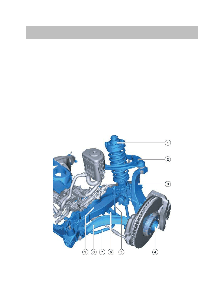
F01/F02 Front axle components

The introduction of a second control arm level for wheel control, which is arranged above
the wheel, results in additional degrees of freedom for the kinematics of the front axle as
well as for the suspension/damping compared to other designs such as a spring strut
front axle.
Components with special materials:
• The forged aluminum swivel bearing (3) with the 3rd generation wheel bearing (4).
Note: The arms and links are bolted by means of ball/disc connections to the
swivel bearing and, similar to the track rod heads, no longer have
tapered screw fittings.
• The transverse control arm at the top (2) is made from forged aluminum and the
cylindrical joint pin is clamped in the swivel bearing (3).
• Tension strut with hydraulic mount (8) and lower transverse control arm (6) are
forged aluminum components while the lower control arm bears the spring strut (1)
by means of a forged steel mount.
• The new front axle subframe (9) is a welded aluminum structure which, as the
standard axle, does not require the familiar aluminum thrust panel with service open-
ings for increasing stiffness. This is made possible by the solid transverse section in
the front axle subframe.
Note: The design layout of the front axle subframe makes it possible to lower
the complete steering gear for service purposes.
9
F01 Chassis and Suspension
Index
Explanation
Index
Explanation
1
Spring strut
6
Transverse control arm, bottom
2
Transverse control arm, top
7
Stabilizer bar
3
Swivel bearing
8
Tension strut with hydraulic mount
4
Wheel bearing
9
Front suspension subframe
5
Stabilizer link
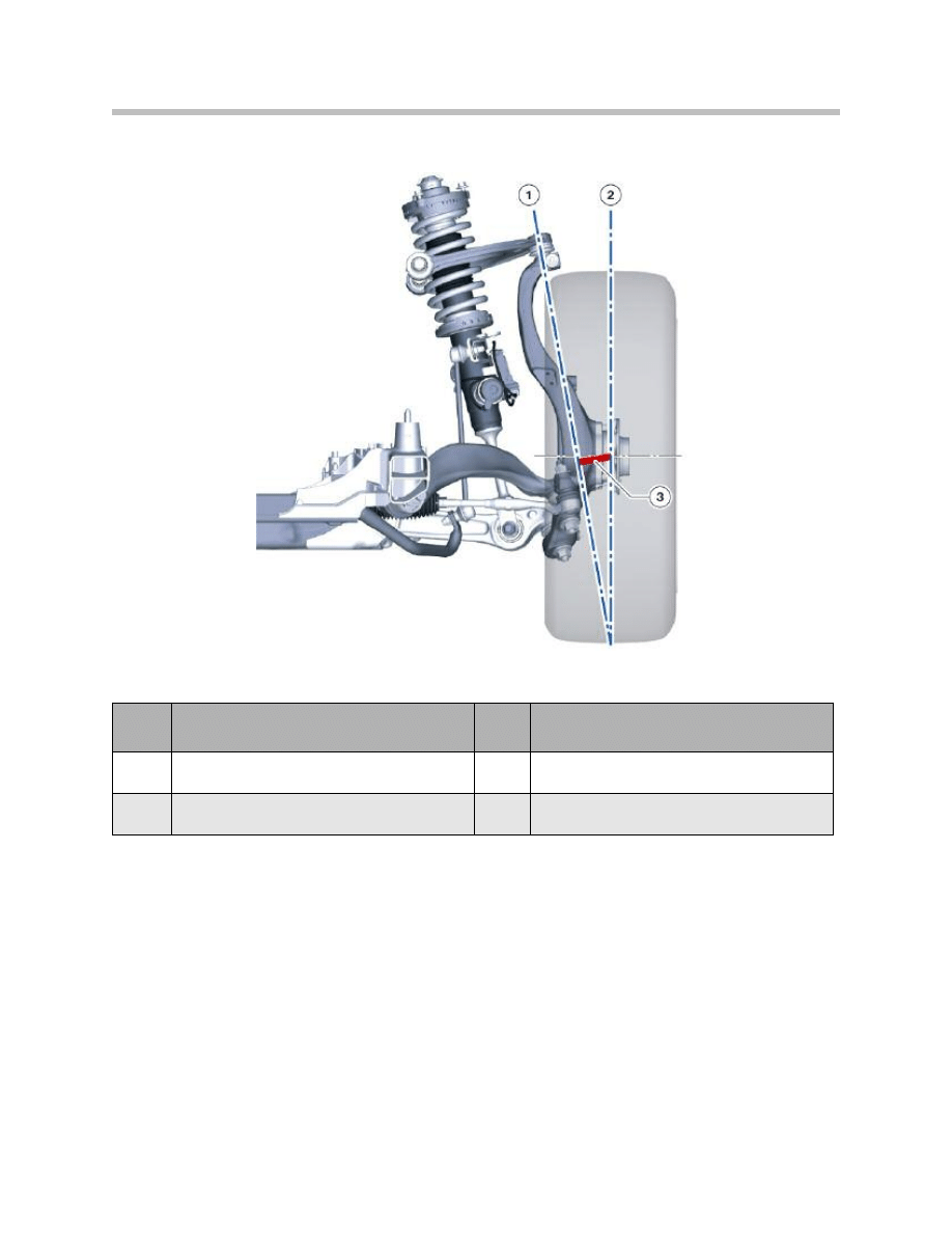
Virtual pivot point or steering pivot axis
The steering pivot axis of the wheel suspension is now formed by a joint at the top A-arm
and the virtual pivot point of the lower arm level as known from the spring strut or
McPherson front axle.
The steering pivot axis is therefore freely selectable and can be positioned such as to
produce a small kingpin offset at hub with sufficient weight recoil.
This kingpin offset at hub is decisive for transmitting the irregularities on the road surface
to the steering wheel. The lower and upper arm levels now move simultaneously in
response to wheel deflection. As a result, as the spring compresses, the wheel pivots in
such a way that the negative camber to the road does not decrease as much as is the
case with a spring strut front axle.
10
F01 Chassis and Suspension
Index
Explanation
Index
Explanation
1
Steering pivot axis
3
Kingpin offset at hub
2
Wheel center plane
Kingpin offset at hub

Since the two control arm levels undertake the wheel control, the damper is virtually no
longer subjected to transverse forces and rotational motion.
This makes it possible to do without a roller bearing assembly (conventional strut mount)
on the spring strut support. Instead of this conventional roller bearing a damping and sup-
port unit is installed that takes up all three load paths. The load paths are the damper pis-
ton rod, the inner auxiliary spring and the bearing spring. This damping and support unit
is still referred to as the “strut mount”.
Due to the lack of transverse forces, the piston rod can be made thinner, resulting in a
similar displacement volume in the push and pull direction of the damper. This serves to
improve the design layout of the damper and is the prerequisite for the innovative damper
control system - vertical dynamics control (VDC).
Due to the substantially lower friction at the circumference of the piston rod, the damper
can respond more sensitively.
By connecting the stabilizer bar via the stabilizer link to the spring strut, the torsion in
response to body roll motion is equivalent to the total wheel lift from the inside to the out-
side of the curve (in other suspension setups, the stabilizer bars are connected to a trans-
verse control arm and therefore achieve only a fraction of the torsion angle). Despite
being highly effective, this high degree of torsion allows for the stabilizer bar to be made
relatively thin which has a favorable effect on driving comfort and dynamics as well as
saving weight.
Comparison of front axle technical data
11
F01 Chassis and Suspension
Description (Front axle data)
E65/E66
F01/F02
Kingpin offset at hub (mm)
88.1
56.3
Track width (mm)
1578
1611
Camber
-0° 20' ±20'
-0° 12' ±15'
Camber difference
0° ±30'
0° ±30'
Total toe-in
10' ±8'
16' ± 6'
Turning circle (m/ft)
11.92/39.10
12.15/39.86
Kingpin offset (mm)
0
0.5
Toe angle difference (toe out on turns)
1° 27' ±30'
12° 20'
Caster angle
7° 27' ± 30'
7° 0'

Cast aluminium spring support (body side)
On the E70, a cast aluminum spring support was used for the first time on the front end
of the X Series. This assembly is now also used on the F01/F02. It offers the following
advantages:
• Reduced weight through intelligent lightweight construction
• Improved driving dynamics thanks to higher degree of stiffness
• Less components therefore reduced manufacturing expenditure.
The cast aluminum spring support takes up the forces from the chassis and suspension
and directs them into the car body. Both the spring strut as well as the upper transverse
control arm are secured to the cast spring support. The component must exhibit a high
degree of stiffness for this purpose. This is achieved by optimum material distribution by
ensuring material is only accumulated where necessary. The spring support therefore
represents an important contribution to controlling driving characteristics as it takes up
both static and dynamic wheel forces. Since, with the cast construction, it is possible to
integrate many individual functions and components in one single component, compared
to the conventional shell construction, this setup is distinctly more compact while making
a significant contribution to reducing weight.
• The cast aluminum lightweight construction reduces the weight by approx. 50 %
compared to the conventional sheet steel construction
• More useful package space compared to conventional sheet steel construction -80
mm shorter front end
• Function-compliant design with specific local stiffening points adding to lightweight
construction
• Integration of various brackets for mounting units etc. in the cast aluminum spring
support with add-on parts.
The cast aluminum spring support is connected to the neighboring steel components
(e.g. engine support) by means of a rivet-adhesion structure. The structure is of lower
weight while making it possible to reduce the number of parts (no additional sheet metal
brackets). Nevertheless, the vehicle body is more stable and torsionally rigid while
increasing local stiffness. This design arrangement has a positive effect on improved
driving dynamics.
Service
Note: The camber can also not be adjusted on the double wishbone front axle.
As for the E70/ E71, two replacement upper transverse control arms are
available for the F01/F02 should the camber need to be changed (e.g.
after an accident). These replacement upper transverse control arms
enable positive (+5 mm) and negative (-5 mm) correction.
12
F01 Chassis and Suspension

13
F01 Chassis and Suspension
Front axle wheel alignment is required during service when:
Screw Connections are Released
Front axle subframe to body (lowering)
NO
Steering gear unit to front axle subframe
YES
Lower transverse control arm to front axle subframe
YES
Lower transverse control arm to swivel bearing
NO
Tension strut to front axle subframe
NO
Tension strut to swivel bearing
NO
Upper transverse control arm to body
NO
Upper transverse control arm to swivel bearing
NO
Track rod to steering gear
NO
Track rod head to track rod
YES
Track rod head to swivel bearing
NO
Spring strut to lower transverse control arm
NO
Strut mount to body
NO
Lower steering shaft to steering gear
NO
Steering column to lower steering shaft
NO
Component/screw Connection is Replaced
Front axle subframe
YES
Steering gear
YES
Transverse control arm, bottom
YES
Rubber mount for lower transverse control arm
YES
Tension strut
NO
Rubber mount for tension strut
NO
Transverse control arm, top
NO
Rubber mount for upper transverse control arm
NO
Track rod
YES
Swivel bearing
YES
Wheel bearing
NO
Spring strut
NO
Coil spring
NO
Mount
NO

Rear Axle
Highlight in F01/F02
The integral-V rear axle is a revolutionary further development of the integral IV rear axle
now installed in many BMW models.
The integral IV rear axle fulfils the primary function of the running gear and wheel control
in a unique way while making a significant contribution to driving dynamics characteristic
of a BMW.
Safety functions are defined by the superior vehicle control characteristics. Effective
decoupling of the road and drive train guarantees outstanding levels of acoustic and
vibration comfort.
The further developed integral-V rear axle in the F01/F02 also provides these properties.
In addition, the new rear axle has been specifically tuned to the new requirements of the
F01/F02:
• Larger vehicle dimensions
• Greater total weight
• Greater drive output
• Higher drive torque
• Runflat tires.
In addition, the demanding objectives relating to driving dynamics and comfort have been
correspondingly adapted while the new system integrates driving dynamics systems
required for this purpose.
The integral-V rear axle primarily fulfils the driving dynamics functions of the mechanical
chassis and suspension, i.e. define elastokinematic wheel control in all relevant driving
situations.
The particularly innovative BMW development of the integral active steering (IAL), howev-
er, makes specific demands in terms of the elastokinematics of the integral-V rear axle:
To a certain extent, the wheels on the rear axle must be able to execute steering move-
ments.
Kinematics and elastokinematics
The spatial arrangement of the pivot points or pivot axes of the arms and links is known
as kinematics. This term applies to components that are assumed to be non-deformable.
Elastokinematics takes into account the flexibility at least of the rubber-metal mounts,
often of the ball joints and rarely of the components.
Various arms define the horizontal plane of the rear axle wheel suspension at the axle car-
rier and the wheel carrier. These arms are mounted such that they can rotate about an
approximately horizontal axis of rotation and therefore allow vertical movement of the
wheel carrier.
14
F01 Chassis and Suspension

Kinematics is primarily of significance in terms of vehicle handling. The kinematics is
arranged such that defined camber and toe-in angles are achieved between the wheel
and road surface in response to the suspension and steering.
Kinematics is superimposed by elastokinematic effects. These elastokinematic effects
occur as the movement points and movement axes are spatially displaced by the effect of
the forces at the wheel.
New challenge for the integral rear axle
In terms of the F01/F02, the new integral active steering (IAL) as a BMW driving dynam-
ics innovation, posed a completely new challenge to the engineers and the tried and test-
ed integral IV rear axle.The integral active steering is made up of the active steering and
the rear axle slip angle control (HSR).
15
F01 Chassis and Suspension
Index
Explanation
Index
Explanation
1
Actuator, rear axle slip angle control (HSR)
6
Integral link
2
Track rod, left
7
A-arm (swinging arm)
3
Transverse control arm, top
8
Thrust strut
4
Wheel carrier
9
Rear axle carrier
5
Wheel bearing
Components of the integral V rear axle with integral active steering
The principle of the integral-V rear axle makes it possible to resolve the conflict between
driving dynamics and comfort. The dynamic and drive forces applied through the wheel
contact point into the wheel suspension are taken up by the wheel carrier, rear axle carrier,
three links and an A-arm (swinging arm).
The design layout reduces the flexible pulling action in the wheel carrier and therefore
enables lengthways damping of the wheel control, which is important for rolling comfort,
by means of axially soft front link mounts on the rear axle carrier.
Thanks to the position of the spring on the wheel carrier, it is no longer necessary to
support the weight of the vehicle on the rubber mounts on the rear axle carrier.
This optimum spring position in conjunction with specific lengthways control guarantees
effective isolation of rolling and drive noise while significantly contributing to the refined
smooth and quiet vehicle running characteristics.
16
F01 Chassis and Suspension
Index
Explanation
Index
Explanation
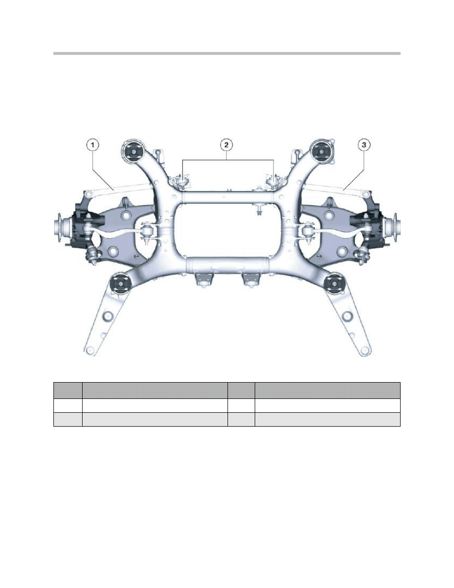
1
Track rod, right
3
Track rod, left
2
Bearing assemblies, track rod
Integral V rear axle without integral active steering

The main criteria that governed the selection of materials included component weight,
production process (cold forming, casting properties, welding properties), strength and
deformation characteristics as well as corrosion resistance.
Two versions of the integral-V rear axle are available. Bearing assemblies are fitted on the
two track rods if the vehicle is not equipped with integral active steering.
The revolutionary further development of the integral IV rear axle culminates in the BMW
patented integral-V rear axle. The new arrangement of the arms and links as well as the
use of ball joints facilitates a rear axle with steering capabilities.
Arm arrangement, E65 integral IV rear axle
Viewing the arrangement of the arms and links in the integral IV rear axle of the E65 it is
difficult to imaging that defined steering movement of the rear wheels about the Z-axis
could be realized.
17
F01 Chassis and Suspension
Index
Explanation
Index
Explanation
A
Top view (forward direction x)
5
Rubber mount
B
Bottom side view
6
Rubber mount
1
Angle joint
7
Rubber mount
2
Angle joint
8
Rubber mount
3
Rubber mount
9
Ball joint
4
Rubber mount
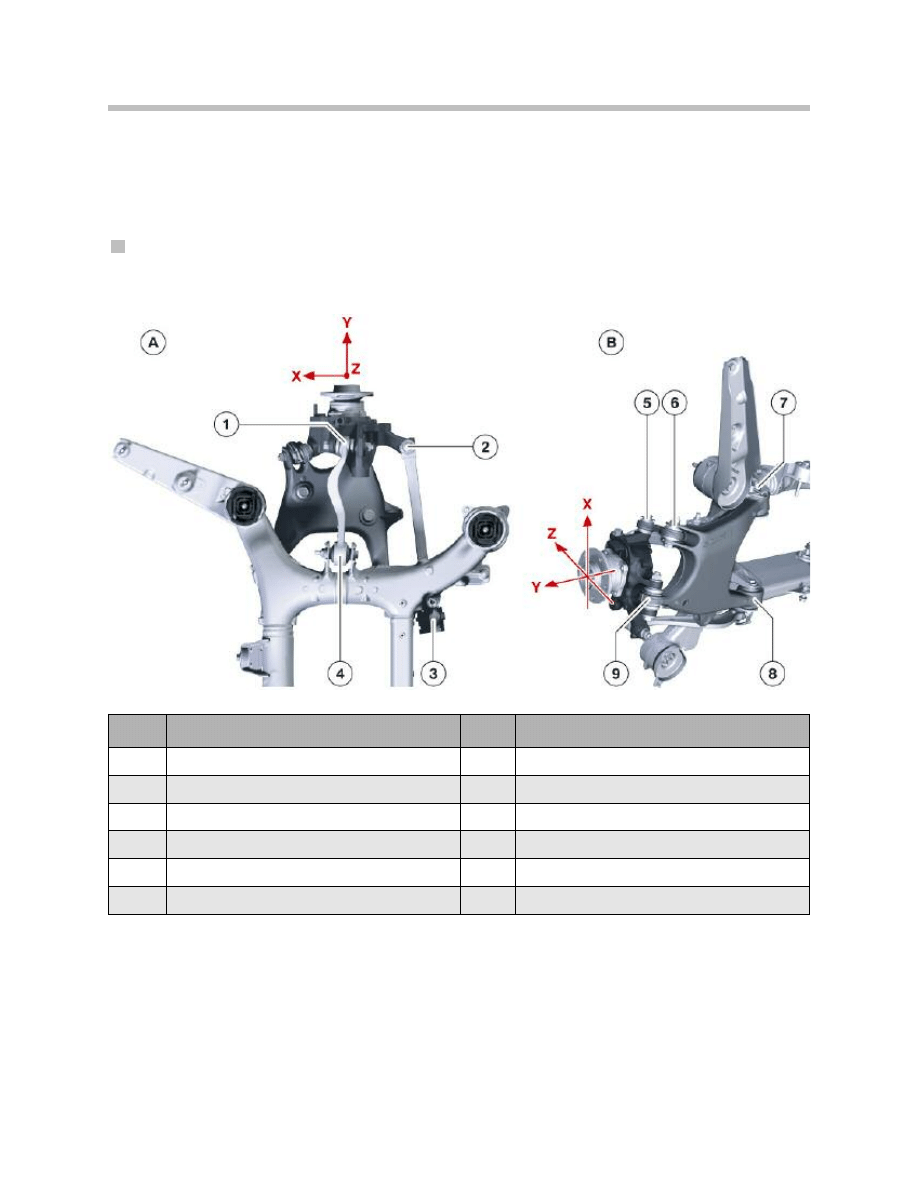
Theoretically, i.e. kinematically, the design of the integral IV rear axle could facilitate steer-
ing capabilities, however a large actuator would be required that could not be accommo-
dated in the package space available on the F01/F02. This would have to be designed
considerably longer and would therefore be decisively heavier and more expensive.
Arm arrangement, integral-V rear axle in the F01/F02
Summary of the design layout:
The system consists of a wheel carrier that is controlled from below by a torsionally rigid
A-arm (swinging arm).
At the bottom, the wheel carrier is connected directly by means of a first bearing mount
and indirectly by means of a second bearing mount, in connection with an integral link
arranged vertically with respect to the plane of the A-arm (swinging arm), to the wheel
carrier.
18
F01 Chassis and Suspension
Index
Explanation
Index
Explanation
A
Top view (forward direction x)
5
Rubber mount
B
Bottom side view
6
Rubber mount
1
Ball joint
7
Rubber mount
2
Ball joint
8
Rubber mount
3
Rubber mount
9
Ball joint
4
Ball joint

The two rubber mounts on the inside of the vehicle are connected to the rear axle carrier
such that they are torsionally soft and can be displaced axially.
The upper transverse control arm lies approximately in the vertical plane of the drive shaft
and therefore also at the center point of the wheel.
The rear track rod arranged approximately at the center point of the wheel is either
mounted on the rear axle carrier or connected to the actuator of the integral active steer-
ing.
Service
Note: The track and camber at the rear axle can still be adjusted by means of
two eccentric screws, however, a new procedure must be observed!
19
F01 Chassis and Suspension
Description (Rear axle data)
F01 (Standard)
F01 (optional HSR)
Whee base (mm)
3070
3070
Track width
1628
1650
Camber
-1° 50' ±15’
-1° 50' ±15’
Camber difference
0° ±30'
0° ±30'
Total toe-in
14' ±10’
16' ± 6'
Thrust angle
0° ±12'
0° ±12'

Damping/suspension
The standard chassis and suspension system of the F01 features steel springs on the
front and rear axle. The standard chassis and suspension on the F02 has steel springs
on the front axle with the single axle air suspension (EHC) fitted on the rear axle. The
F01/F02 is equipped as standard with vertical dynamics control featuring electronically
controlled damper systems. In addition, the following combinations are available:
• Standard suspension with single axle air spring
• Dynamic drive with steel springs and VDC dampers
• Dynamic drive with 2 steel springs and single axle air spring and VDC dampers.
BMW is the first car maker to offer as standard a continuously controlled adjusting
damper system irrespective of tension/compression.
The outstanding properties of this new (VDC2) adjusting damper are:
• Advanced opening adjustment for improved body stabilization. Realized by adjust-
ments even at low damper speeds.
• Difference between “soft” and “hard” in connection with driving dynamics control
easily identifiable by the customer.
• Separately tuned identifier for rolling comfort through tension characteristics irre-
spective of compression.
20
F01 Chassis and Suspension

21
F01 Chassis and Suspension
Brakes
Function-optimized lightweight construction brakes are used on the F01/F02.
Lightweight brake rotors with riveted aluminum hubs are installed on the front axle, while
cast iron rotor are used on the rear axle.
Floating brake calipers are fitted on the front and rear axle. The brake system in the F01/
F02 features the known brake wear monitoring system for the CBS indicator.
Technical data, front axle:
Technical data, rear axle:
Brake caliper
Brake calipers with optimized function and efficiency are fitted on the F01/F02.
The frame structure of the floating caliper effectively uses the package space available in
the wheel.
In connection with effective brake cooling, the brake system achieves a high degree of
thermal efficiency. The aluminum housing of the floating caliper saves weight while
ensuring maximum operating efficiency.
Brake disc
The familiar riveted aluminum hub also saves weight while drastically reducing the shield-
ing effect that may occur under harsh braking conditions, i.e. deformation of the brake
disc caused by thermal material expansion. Internally ventilated brake discs are fitted on
the front and rear axle.
Technical data, front brakes
Specification
Brake caliper, piston diameter (mm)
60
Brake disc, thickness (mm)
36
Brake disc diameter (mm)
373
Brake disc diameter (inches)
14.7
Brake disc construction
Aluminum (riveted)
Brake caliper construction
Aluminum
Technical data, rear brakes
Specification
Brake caliper, piston diameter (mm)
44
Brake disc, thickness (mm)
24
Brake disc diameter (mm)
368
Brake disc diameter (inches)
14.5
Brake disc construction
Cast iron
Brake caliper construction
Cast iron
Steering
The steering column in the F01/F02 is ergonomics, comfort and passive occupant
designed to conform with the most safety all coupled with characteristic BMW demand-
ing requirements in terms of steering properties.
The F01/F02 is equipped with an electrically operated steering column with infinitely vari-
able horizontal and vertical adjustment as standard.
• Outstanding ergonomics ensured by an optimum adjustment range for the steering
wheel position:
– Horizontal ± 30 mm
– Vertical ± 20 mm
• Additional comfort function provided by easy entry and exit:
– When getting in and out of the vehicle, the steering wheel temporarily moves into
the topmost position thus providing maximum freedom of movement.
• Outstanding crash safety provided by the familiar, innovative BMW crash system,
specifically tuned and featuring force-dependent energy absorbers.
22
F01 Chassis and Suspension
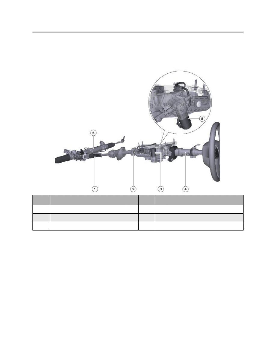
Index
Explanation
Index
Explanation
1
Splined tube
4
Crash tube
2
Flexible coupling
5
Actuator motor, right
3
Actuator motor, left
6
Steering gear
Steering column F01/F02
The steering column has a motor for in/out adjustment and a motor for up/down adjust-
ment with a specially developed gear mechanism.
Each of these low-noise drive units is mounted acoustically decoupled executes the
adjustment with the aid of motor/driven flexible spindles.
The components of the steering column are optimized in terms of rigidity in the comfort-
relevant frequency range to reduce vibration and avoid disturbing steering wheel vibration
and have been developed in line with a magnesium and aluminium lightweight construc-
tion concept.
The flexible coupling fitted in the steering column represents the perfect means of finely
tuning the steering characteristics and driving comfort. Vehicle-specific loop packages
are vulcanized in elastomer in this flexible coupling, allowing extremely high torque to be
transmitter reliably and precisely. The steering column is thus successfully decoupled
from disturbing influences caused by excitation from the road surface (axial impact or radi-
al torque peaks).
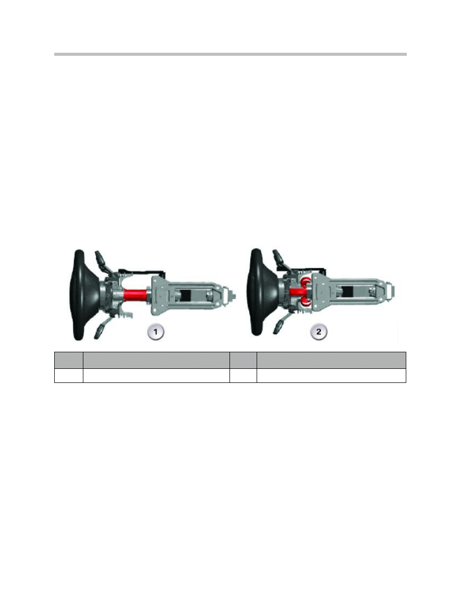
The innovative crash system essentially consists of a crash adapter and crash tube. In the
event of a crash, the impact energy is progressively reduced for the driver by the crash
tube breaking open and deforming, thus providing the advantage of reduced stress on
the occupants in the event of a crash (integral part of the 5-star philosophy at BMW).
In addition, the lower and center steering shaft collapses during the crash thus preventing
penetration of the steering column into the passenger compartment. The system design
also prevents the back displacement of all components in the engine compartment and
possible damage to the bulkhead.
23
F01 Chassis and Suspension
Index
Explanation
Index
Explanation
1
Normal position (travel range 0 mm)
2
Crash position (travel range 80 mm)
Example: Crash sleeve on steering column

Wheels and Tires
Unlike the E65 predecessor, the F01/F02 is fitted with the RunFlat System Component
RSC package on board as standard.
Highlights of the safety tires:
The BMW Group has put together a safety package with the aim of avoiding such acci-
dents as well as the risk involved with changing a tire at the side of the road, at night or in
wet conditions, in tunnels or at road construction.
The BMW runflat safety system:
• Warns the driver in good time of imminent tire pressure loss so that countermea-
sures can be taken
• Allows the journey to be continued for a defined distance even in the event of com-
plete loss of tire pressure
• Keeps the tire safely on the rim even in the event of sudden tire pressure loss at high
speed.
The system consisting of the RSC tires, rims with EH2+ contour and the electronic tire
pressure monitoring system (TPMS), renders a spare wheel or space-saver wheel, break-
down kit or vehicle jack unnecessary and this creates more storage space in the luggage
compartment while also saving weight.
Extended Hump rims (EH2+)
The specially shaped rim humps ensure that the RSC tire cannot detach from the rim
even in the case of sudden tire pressure loss. This means substantially greater safety par-
ticularly when driving at high speed and on winding roads.
TPMS
The Tire Pressure Monitoring Systemmonitors the tire pressure via wheel mounted pres-
sure sensors. A warning lamp informs the driver of any irregularities that occur due to the
loss of tire pressure.
Note: The TPMS system does not exempt the driver from regularly checking
the tire pressure.
After changing the tire pressure or after changing a tire, the TPMS systemmust be reini-
tialized in order to restore the target values with the correct tire pressure.
The entire safety package consists of three components:
• Runflat tires
• Extended hump rims (EH2+)
• Tire Pressure Monitoring System (TPMS)
24
F01 Chassis and Suspension

RSC tires with emergency running properties
With its reinforced side walls, additional strip inserts and heat-resistant rubber mixtures,
even when completely depressurized, the “self-supporting tire” makes it possible to con-
tinue the journey for a limited distance at a maximum speed of 50 mph. This means each
tire is also its own spare wheel.
The maximum range after complete tire pressure loss is:
• approximately 250 miles at low vehicle load
• approximately 150 miles at medium vehicle load
• approximately 50 miles at high vehicle load.
ABS, ASC and DSC remain fully operational even in the event of complete tire pressure
loss.
When driving with a run flat tire with no pressure, the standard VDC automatically distrib-
utes the vehicle weight over the remaining wheels so as to relieve the load on the depres-
surized tire with the aim of achieving the highest possible range for continued operation.
F01/F02 Wheel sizes
For the benefit of creating a sports appearance and to improve the overall design, com-
pared to the E65/E66 the track width on the F01/F02 has been increased while the
wheel arch overhang has been reduced to a minimum.
In addition, the entire range of wheels for the F01/F02 has been aligned flush by corre-
spondingly matching the outer rim offset so that, with the exception of the different rim
dimensions, there are no longer any differences between the tire sizes.
The following table lists the standard wheels on the F01/F02.
25
F01 Chassis and Suspension
Explanation
750i
750Li
Front tire
245/50 R 18 Y 100 Y RSC
245/50 R 18 Y 100 Y RSC
Rear tire
245/50 R 18 Y 100 Y RSC
245/50 R 18 Y 100 Y RSC
Front rim
8J x 18 EH2+LM - IS30
8J x 18 EH2+LM - IS30
Rear rim
8J x 18 EH2+LM - IS30
8J x 18 EH2+LM - IS30
Document Outline
- Main Menu
- 01_F01 Introduction
- 02_F01 Powertrain
- 03_F01 Voltage Supply & Bus Systems
- 03.1_F01 Bus Systems
- 03.2_F01 Voltage Supply
- 03.3_F01 Energy Management
- 03.4_F01 Car Access System 4
- 04_F01 Chassis Dynamics
- 04.1_F01 Chassis and Suspension
- 04.2_F01 Dynamic Driving Systems
- 04.3_F01 Longitudinal Dynamics Systems
- 04.4_F01 Lateral Dynamics Systems
- 04.5_F01 Vertical Dynamics Systems
- 04.6_F01 Cruise Control Systems
- 05_F01 General Vehicle Electronics
- 05.1_F01 Comfort Access
- 05.2_F01 Central Locking System
- 05.3_F01 Automatic Soft Close
- 05.4_F01 Power Windows
- 05.5_F01 Sliding Tilting Sunroof
- 05.6_F01 Anti-theft System
- 05.7_F01 Automatic Luggage Compartment Lid
- 05.8_F01 Exterior Lighting
- 05.9_F01 Interior Lighting
- 05.10_F01 Wiper-Washer System
- 05.11_F01 Exterior Rear View Mirrors
- 05.12_F01 Seats
- 05.13_F01 Steering Column Switch Cluster
- 06_F01 Driver Information Systems
- 06.1_F01 Displays Indicators and Controls
- 06.2_F01 Head-up Display
- 06.3_F01 BMW Night Vision 2
- 06.4_F01 Active Blind Spot Detection System
- 06.5_F01 KAFAS
- 06.6_F01 PDC-TRSVC
- 07_F01 Information and Communication Technology
- 07.1_F01 Rear Seat Entertainment Systems
- 07.2_F01 Telephone System
- 07.3_F01 Voice Activation System
- 07.4_F01 Audio Systems
- 08_F01 Climate Control
- 09_F01 Passive Safety Systems
- 10_F01 Service Information
- 10.1_F01 System Functions
- 10.2_ISTA-Programming
Wyszukiwarka
Podobne podstrony:
05 M Chassis and Suspension
PBO G 04 F01 QSMS document distribution list
Clio Braking and Suspension
William Noble Conflict, Action and Suspense
04 6 F01 Cruise Control Systems
04 AC System and Components
Esther M Friesner A Beltaine And Suspenders
04 Emotional Intelligence and Emotion Regulation S
04 3 F01 Longitudinal Dynamics Systems
Isaac Asimov Lucky Starr 04 Lucky Starr and the Oceans of Venus
Zelazny, Roger Amber Short Story 04 The Shroudling and the Guisel
Friesner, Esther A Beltaine and Suspenders
04 4 F01 Lateral Dynamics Systems
Esther M Friesner A Beltaine And Suspenders
04 E60 M5 Chassis & Suspension
PBO SDO6 F01 Reviewing records to contract and agreement
USŁUGI, World exports of commercial services by region and selected economy, 1994-04
Popular Mechanics Fixing Suspension Clunks and Rattles
04 Emotions and well being across cultures
więcej podobnych podstron