
Initial Print Date: 09/05
Table of Contents
Subject
Page
Calipers . . . . . . . . . . . . . . . . . . . . . . . . . . . . . . . . . . . . . . . . . . . . . . . . . . . . . . .6
Rotors . . . . . . . . . . . . . . . . . . . . . . . . . . . . . . . . . . . . . . . . . . . . . . . . . . . . . . . . .7
Introduction . . . . . . . . . . . . . . . . . . . . . . . . . . . . . . . . . . . . . . . . . . . . . . . . . . . .8
System Components . . . . . . . . . . . . . . . . . . . . . . . . . . . . . . . . . . . . . . . . . .12
Operating Modes of the MK60E5 . . . . . . . . . . . . . . . . . . . . . . . . . . . . .14
MDynamic Mode (MDM) . . . . . . . . . . . . . . . . . . . . . . . . . . . . . . . . .14
Brake Readiness . . . . . . . . . . . . . . . . . . . . . . . . . . . . . . . . . . . . . . . . .15
Dry Braking . . . . . . . . . . . . . . . . . . . . . . . . . . . . . . . . . . . . . . . . . . . . .15
Hill Ascent Assistant . . . . . . . . . . . . . . . . . . . . . . . . . . . . . . . . . . . . .15
Condition Based Service (CBS) . . . . . . . . . . . . . . . . . . . . . . . . . . .15
E60 M5 Chassis & Suspension
Revision Date:

2
E60 M5 Chassis & Suspension
Chassis & Suspension
Model: E60 M5
Production: from 9/2005
After completion of this module you will be able to:
• Familiarize yourself with the suspension system used in the vehicle
• Familiarize yourself with the brake on the vehicle
• Understand the changes to the DSC system
3
E60 M5 Chassis & Suspension
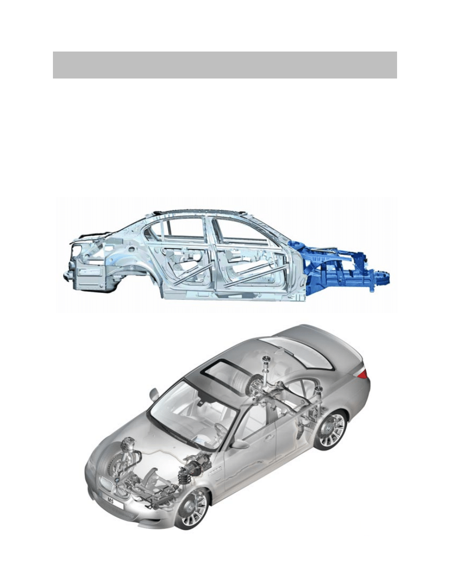
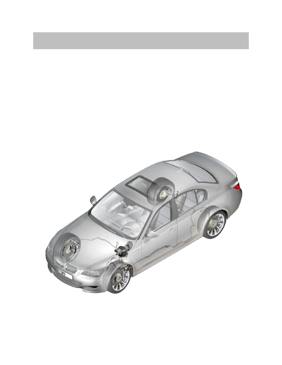
The E60 M5 utilizes the same body construction as the production based 5 Series E60.
The main body is made of steel and the front end utilizes the familiar GRAV technology.
GRAV is an acronym of "gewichtsreduzierter Aluminiumvorderbau" and this lightweight
aluminium front end enhances the lightweight design of the car. Almost the entire front
end is made of aluminium.
The transition to steel in the composite construction starts in the vicinity of the engine
bulkhead. The reduced weight of the front end in particular contributes much to the ideal
axle-load distribution of 50:50.
Chassis & Suspension
4
E60 M5 Chassis & Suspension
The suspension system used on the E60 M5 is carried over from the production based
E60 5Series sedans.
The control arms and transverse links are made of aluminium and ensure high-precision
tracking of the wheels. The highly innovative design principle with the special layout of
the leading links and control arms ensures high-precision steering. The low axle loads,
especially in the area of the front axle, also provide for a high degree of agility and familiar
BMW handling characteristics.
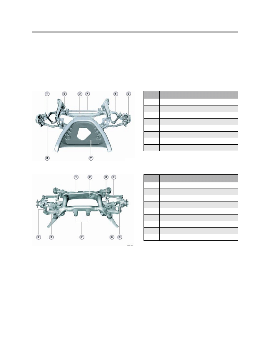
Index
Explanation
1
Stabilizer Link
2
Hydro-Mount
3
Front Axle Carrier
4
Stabilizer Bar (No ARS)
5
Tension Strut
6
Swivel Bearing
7
Reinforcement Plate
8
Control Arm
Index
Explanation
1
Axle Carrier
2
Differential Bearing, rear
3
Stabilizer Bar
4
Control Arm
5
Traction Strut
6
Thrust Rod
7
Differential Bearing, front
8
Swinging Arm
9
Integral Link
Front Axle
Rear Axle
5
E60 M5 Chassis & Suspension
The continuously variable electronic damping control (EDC-K) system used in the E65/6
is used in the E60 M5.
The continuous Electronic Damping Control (EDC-K) absorbs vertical forces while
driving and dampens these forces to the chassis.
The forces are measured by two vertical acceleration sensors on the front axle (left and
right) and one at the rear axle (right). The front sensors are located in the wheel housings
and the rear on the trunk tray underneath the trunk ventilation ports. The dampening
characteristics are mapped in the control module to continuously regulate the EDC-K
providing maximum comfort.
The EDC-K works with infinitely variable valves in the dampers to regulate the hydraulic
fluid flow using electromagnetic control valves. EDC-K provides the actual damping
force required at any time.
The steering angle sensor is used along with the front wheel speed sensors to deter-
mine the lateral acceleration. The controller provides the opportunity to select from
three basic settings:
“Comfort” - Comfort-oriented coordination of shock absorbers and steering
“Normal“ - Offers a balanced mixture of the comfort and the sports program
“Sport” - Consistently sporty coordination of shock absorbers and steering.
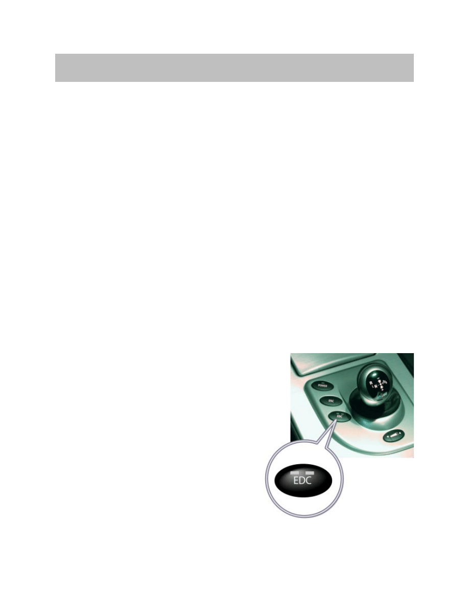
Selecting Program
To select between the three programs available,
press the EDC button repeatedly:
"Comfort": no LED lights up in the button.
"Normal": one LED lights up in the button.
"Sport": both LEDs light up in the button.
The last selected program is active each time the
engine is started.
You can also activate your preferred program with
the button on the steering wheel.
EDC-K
6
E60 M5 Chassis & Suspension
Braking distances equal to top sports car levels. The new BMW M5 owes its enormous
braking power to double piston aluminium brake calipers and perforated, ventilated com-
pound (floating) brake rotors.
The braking distance for the M5 is approximately 118ft from 62 mph to a full stop.
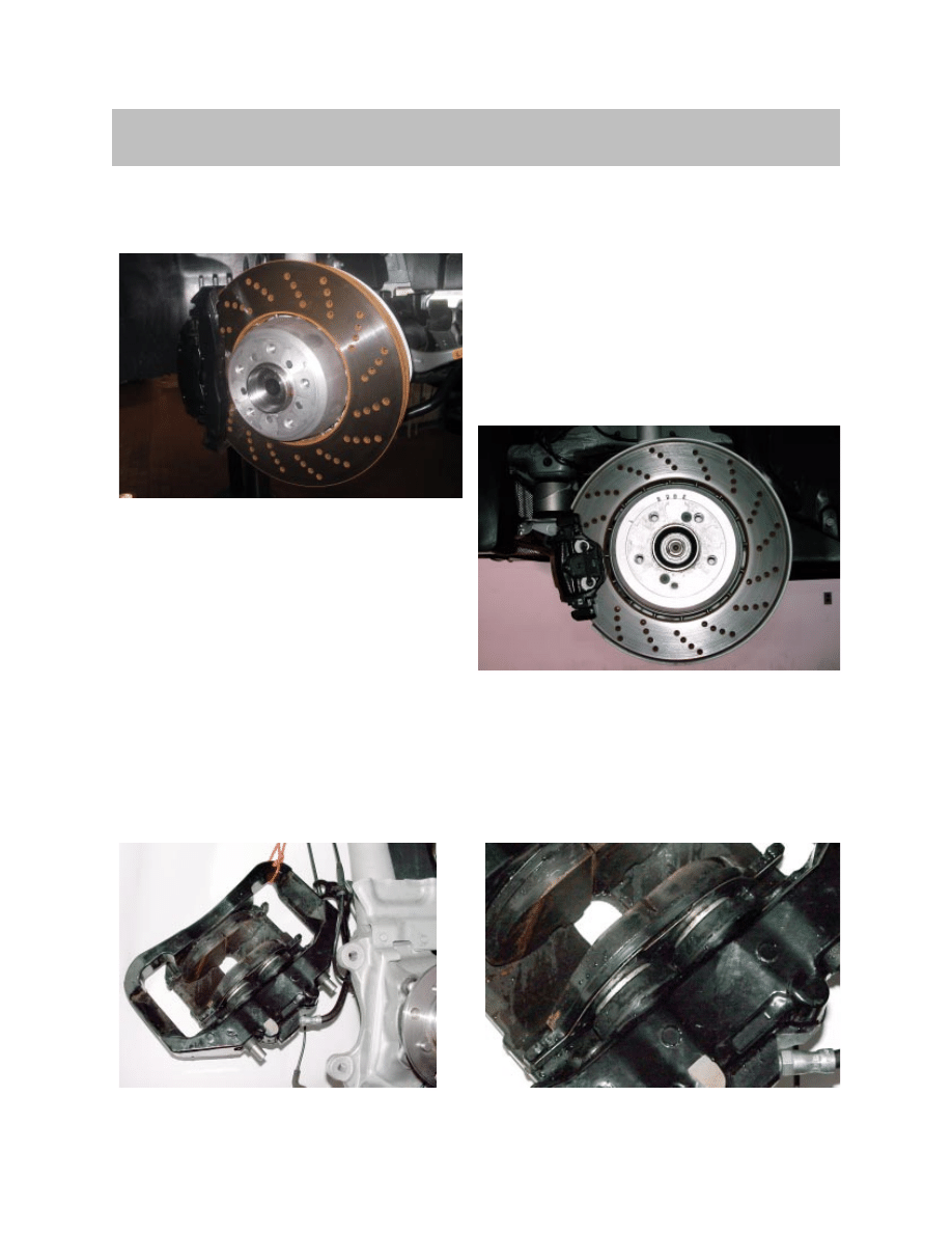
Calipers
The M5 utilizes dual piston brake calipers in the front and conventional single piston
calipers in the rear.
Brakes
Front Brake Rotors
Rear Brake Rotors
Brake rotor measurements front:
374 x 36 mm
Dual Piston Front Brake Caliper
(close-up view)
Brake rotor measurements rear:
370 x 24 mm
7
E60 M5 Chassis & Suspension
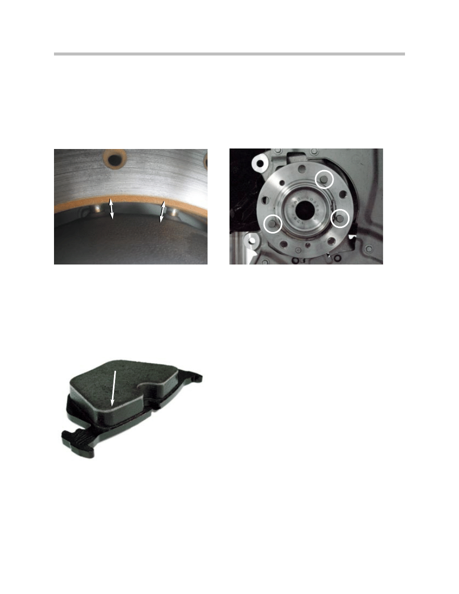
Rotors
Both the front and rear rotors are cross drilled floating type. These ensure optimized heat
dissipation, improved response, as well as reduction of unsprung masses.
The rotor has an aluminum center section (hub) with pins embedded in a radial pattern
that are “connected” to the rotor surface utilizing a free moving or floating configuration.
This allows the rotor surface to contract and expand with the changes in temperature.
The rotor is attached to the hub with two allen style screws and three alignment pins
located on the hub.
The rotor outer ring is cast and holes are drilled out to improve braking. The drilled
surface allows gases that form between the brake pad and rotor to escape. Otherwise,
there would be a thin film of “brake gases” between the surface of the rotor and the
brake pads.
Brake pads are made by gluing the friction
material to a backing plate (metal). These
are then baked in an oven to allow the glue
to cure. While the brakes are heated, gasses
are released and travel through the brake pads
to the surface. This can be seen on any new
brake pads as a lighter upper section of the
brake pad (see picture to the left).
Detail of Rotor Attachment Pins
Rear Brake Pads (“gasses”)
Detail of Rotor Alignment Pins on Hub
8
E60 M5 Chassis & Suspension
Introduction
The E60 M5 is equipped with the Continental Teves Dynamic Stability Control System
(DSC+) MK60E5.
The MK60E5 is a further development of the MK60psi, which is currently used in the
E90. The abbreviation "psi" stands for "pressure sensor integrated" i.e. the two pressure
sensors of the tandem master brake cylinder (THZ) have been combined to form one
plausibility sensor and integrated in the hydraulic unit.
The designation "E5" in MK60E5 signifies the 5 pressure sensors that are integrated
in the hydraulic unit: One pressure sensor that measures the pressure from the tandem
master brake cylinder THZ and four further sensors that measure the braking pressure
of the respective wheel brake.
DSC MK60E5
This system offers functions that were not yet available with the previous system.
New Functions:
• Brake Readiness
• Dry Braking
• Hill Ascent Assistant.
The features of this system distinctly enhance comfort during control intervention while
facilitating even more precise individual wheel braking in connection with the analogue
control valves.
This system has made it possible to reduce the required braking distance less than
previous systems. The E60 M5 has a braking distance of less than 118 feet from a speed
of 62 mph (< 36 m from 100 km/h).
The tire failure indicator (RPA) is integrated in the DSC functions.
9
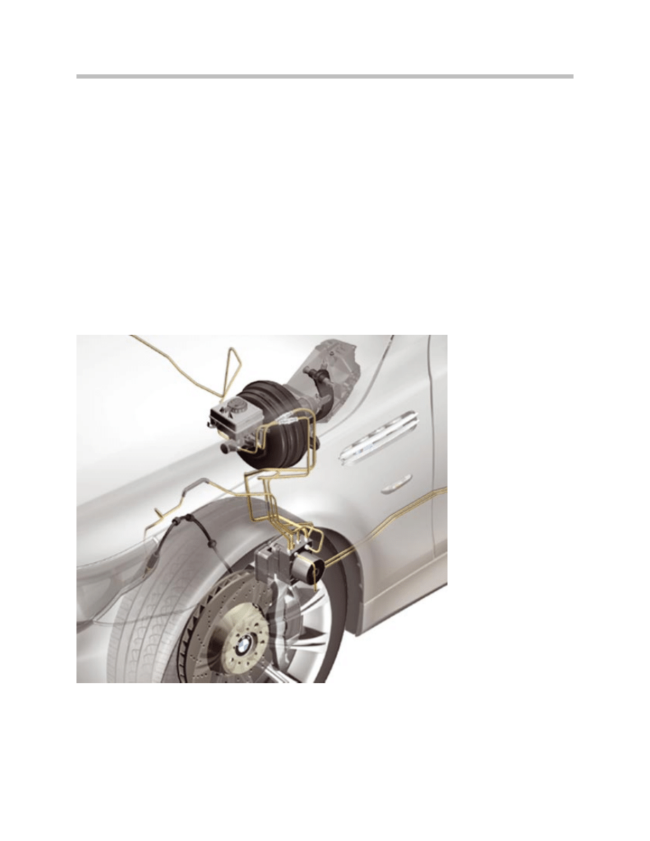
E60 M5 Chassis & Suspension
Mounting Location of DSC Control Unit and Hydraulic Unit
10
E60 M5 Chassis & Suspension
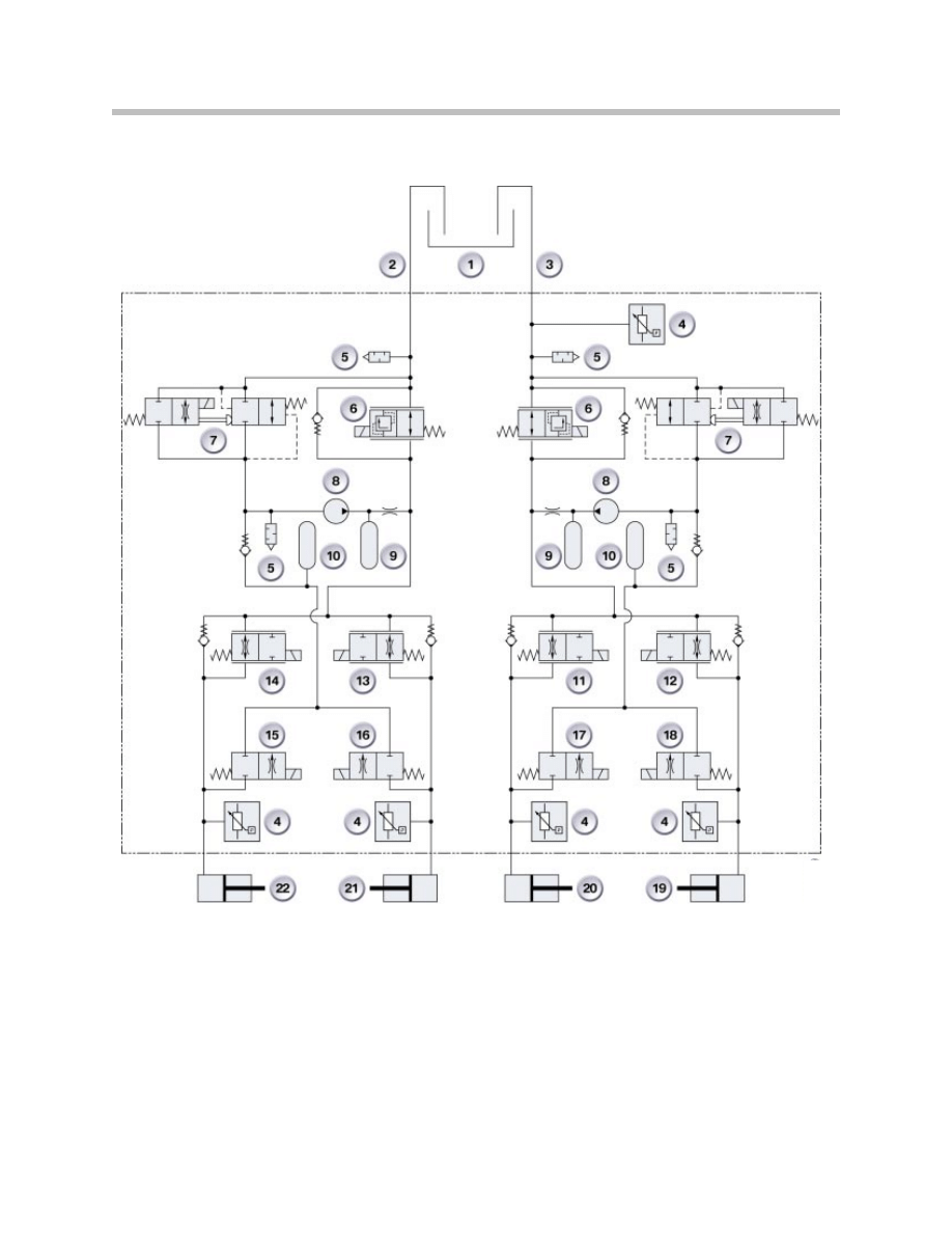
DSC MK60E Hydraulics Diagram

11
E60 M5 Chassis & Suspension
Legend for DSC MK60E Hydraulics Diagram
Index
Explanation
1
Brake Fluid Reservoir
2
Rear Axle
3
Front Axle (hydraulic connection)
4
Pressure Sensor, push rod circuit
5
Pulsation Damper
6
Isolating Valve
7
Electric Changeover Valve
8
Self-Priming Return Pump
9
Damper Chamber
10
Accumulator Chamber
11
Front Left Inlet Valve with Orifice Plate, analog
12
Front Right Inlet Valve with Orifice Plate, analog
13
Rear Right Inlet Valve, analog
14
Rear Left Inlet Valve, analog
15
Rear Left Outlet Valve
16
Rear Right Outlet Valve
17
Front Left Outlet Valve
18
Front Right Outlet Valve
19
Front Right Wheel Brake
20
Front Left Wheel Brake
21
Rear Right Wheel Brake
22
Rear Left Wheel Brake
12
E60 M5 Chassis & Suspension
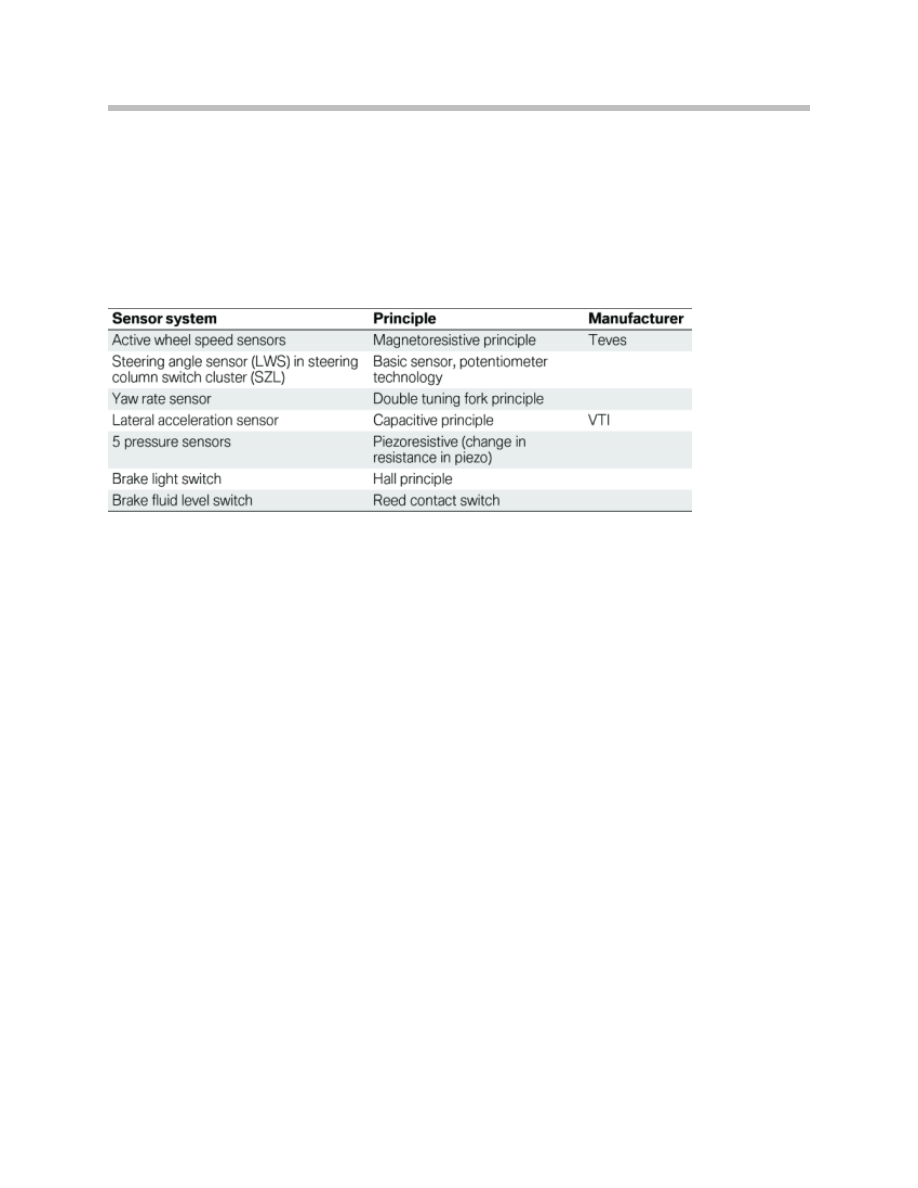
System Components
The predominant differences in the design of MK60E5 compared to MK60psi are:
• Analog valves
• 4 pressure sensors for individual braking pressure acquisition at each wheel.
Sensors
Control Unit
The control unit is mounted behind the left front wheel well cover and is attached
to the hydraulic unit. It consists of:
• Add-on control unit
• Integrated semiconductor relay (motor and valve relay).
Hydraulic Unit
The Teves MK60E5 hydraulic unit consists of:
• Front axle
– 2 analogue inlet valves
– 2 high-speed outlet valves
– 1 isolating valve
– 1 changeover valve
• Rear axle
– 2 analogue inlet valves
– 2 high-speed outlet valves
– 1 isolating valve
– 1 changeover valve.

13
E60 M5 Chassis & Suspension
Pressure Generation
• Pump with two differential piston pump elements
• Operated by means of common eccentric shaft
• 250 W pump motor
• ASC and DSC mode: Self-priming return pump.
Engine Intervention
• Ignition timing adjustment
• Charge control.
Interfaces
• CAN-bus interface (F-CAN, PT-CAN).

14
E60 M5 Chassis & Suspension
Features
Compared to the standard DSC features, the MK60E5 in the E60 M5 has been
upgraded by the following additional functions:
• MDynamic Mode (MDM)
• Brake readiness
• Dry braking
• Hill ascent assistant.
The following functions are not used on the M5:
• Performance control (FLR)
• Soft stop
• Fading brake support (FBS)
• Dynamic traction control (DTC).
Operating Modes of the MK60E5
In principle, the MK60E5 has 3 different operating modes:
• DSC ON
• DSC OFF
• MDynamic mode.
There is no DTC function in connection with the M5. However, similar to DTC mode,
corresponding control thresholds are raised by activating the MDM.
MDynamic Mode (MDM)
MDM gives the performance-oriented driver the option of driving the car with controlled
float angle and longitudinal slip without DSC intervening. The control system intervenes
only when the physical limits are exceeded.
The control thresholds are not static but rather, as the speed increases, they approach
the thresholds of DSC ON mode.
The stability control thresholds are identical as from a speed of approximately 125 mph
(200 km/h) in order not to overtax the driver in the high speed range.
Note: MDynamic Mode can be activated only via the M-Drive.

15
E60 M5 Chassis & Suspension
Brake Readiness
The brake response time is shortened during full brake application by applying the brake
pads to the discs while rapidly restricting the throttle.
This function ensures that a pressure of approx. 3 bar is applied for a period of up to
300 ms to the wheel brakes in order to apply the brake pads already before the expected
application of the brakes. This function facilitates even more rapid response of the brakes.
The function is active as from a speed of 19 mph (30 km/h).
Dry Braking
The brake response characteristics are improved in wet conditions by removing the water
film on the brake discs.
The DSC detects rain and therefore wet brake discs through the permanent operation of
the windscreen wiper motor.
The dry braking function applies approx. 3 bar hydraulic pressure to the wheel brakes
under these conditions. This procedure is repeated every 2-3 km for a period of
approximately 3 seconds when the accelerator pedal is sufficiently depressed (> 10 %),
the vehicle speed is 90 km/h and the brakes were not applied over the last 2- 3 km.
Hill Ascent Assistant
Assistance is provided when driving off on uphill gradients by briefly maintaining a
specific brake pressure in the wheel brakes. This function is active only when the trans-
mission is not in "N" position and the handbrake is released.
DSC ON/OFF has no influence in this case.
The tilt angle (uphill and downhill gradient) is calculated from the measured value of the
longitudinal acceleration sensor. The DSC calculates the necessary holding pressure
based on the uphill or downhill gradient.
After releasing the brake paddle, the braking pressure is immediately decreased to the
calculated holding pressure which is then reduced in stages after a maximum time delay
of 0.7 seconds. The vehicle will start off after approximately 1 seconds if the driver does
not press the accelerator pedal.
The longitudinal acceleration sensor is assigned to the SMG system. The DSC control
unit receives this signal over the bus network.
Note: This function is also active on an incline with reverse gear engaged.
Condition Based Service (CBS)
As in the E60 Series, the MK60E5 calculates and evaluates the condition of the brake
pads.
In contrast to the E60 Series, the M5 is equipped with two brake pad sensors on the
front axle.

16
E60 M5 Chassis & Suspension
Variable M Differential
The variable M differential from the E46 M3 is utilized in the E60 M5 . The variable, rev-
sensing locking differential on the rear axle delivers a key traction advantage, even in very
demanding driving situations.
For example: When the friction coefficients (surface traction) for the two drive wheels
are very different from each other.
By utilizing the internal sheer pump, the locking effect between the left and right wheels
can be up to 100%. This markedly improves handling and stability, enhancing both safe-
ty and driving enjoyment. Sporty drivers in particular enjoy the advantages of the differ-
ential lock – it enhances the positive aspects of rear-wheel drive when driving at higher
speeds and on surfaces with poor traction.
Document Outline
- Main Menu
- E60 M5 Complete Vehicle
- S85 Engine
- MS_S65 Engine Management
- E60 M5 Chassis & Suspension
- SMG III
- E60 M5 Driver Information Systems
Wyszukiwarka
Podobne podstrony:
06 E60 M5 Driver Information
04 E60 Driveline
01 E60 M5 Complete Vehicle
04 E60 E61 Model Update
04 E60 Dynamic Drive
04 1 F01 Chassis and Suspension
Olimpus J 04 M5 klucz
05 M Chassis and Suspension
02 E90 Suspension & Chassis
05 E60 Chassis Dynamics
BEKO chassis 12 8 04
Wykład 04
04 22 PAROTITE EPIDEMICA
04 Zabezpieczenia silnikówid 5252 ppt
Wyklad 04
Wyklad 04 2014 2015
04 WdK
więcej podobnych podstron